Article

Can a Priori Unknown Values of Biomechanical Parameters Be Determined with Sufficient Accuracy in MBS Using Sensitivity Analysis? Analyzing the Characteristics of the Interaction between Cervical Vertebra and Pedicle Screw

1
Institute for Computational Visualistics, University Koblenz-Landau, 56070 Koblenz, Germany
2
Institute of Medical Technology and Information Processing, University Koblenz-Landau, 56070 Koblenz, Germany
*
Author to whom correspondence should be addressed.
These authors contributed equally to this work.
Biomechanics 2022, 2(1), 107-124; https://doi.org/10.3390/biomechanics2010011
Submission received: 21 January 2022 / Revised: 25 February 2022 / Accepted: 27 February 2022 / Published: 10 March 2022
(This article belongs to the Topic Trends and Prospects in Biomechanics)

Abstract

:
Finite element (FE) modeling is a commonly used method to investigate the influence of medical devices, such as implants and screws, on the biomechanical behavior of the spine. Another simulation method is multibody simulation (MBS), where the model is composed of several non-deformable bodies. MBS solvers generally require a very short computing time for dynamic tasks, compared with an FE analysis. Considering this computational advantage, in this study, we examine whether parameters for which values are not known a priori can be determined with sufficient accuracy using an MBS model. Therefore, we propose a many-at-a-time sensitivity analysis method that allows us to approximate these a priori unknown parameters without requiring long simulation times. This method enables a high degree of MBS model optimization to be achieved in an iterative process. The sensitivity analysis method was applied to a simplified screw–vertebra model, consisting of an anterior anchor implant screw and vertebral body of C4. An experiment described in the literature was used as the basis for developing and assessing the potential of the method for sensitivity analyses and for validating the model’s action. The optimal model parameters for the MBS model were determined to be c = 823,224 N/m for stiffness and d = 488 Ns/m for damping. The presented method of parameter identification can be used in studies including more complex MBS spine models or to set initial parameter values that are not available as initial values for FE models.

1. Introduction

Serious trauma, tumors, osteoporosis or inflammatory processes can damage one or more vertebral bodies to such an extent that they are no longer stable. With such massive damage, instabilities and the narrowing of the spinal canal often occur. To stabilize the spine, to prevent irreversible neurological lesions and to reduce the pain of the patient, the affected vertebral bodies are removed and a vertebral body replacement implant is inserted. As anterior implant placements are considered less traumatic and cause less complications than the posterior implant placements, anterior cervical intervertebral body cages combined with plates are commonly used to address these disorders [1].
In various experimental studies, the biomechanical behavior of spinal posterior and anterior pedicle screws has been analyzed. According to Naoum et al. [2], the applications of FE modeling in the spine have contributed to the understanding of bone biomechanics, both in healthy and abnormal conditions, such as scoliosis, fractures, degenerative disc disease and osteoporosis. Rosa et al. [3] aimed to verify the pullout resistance of lumbar pedicle screws obtained by the process of additive manufacturing and to compare them with the screws obtained with traditional techniques. They demonstrated that the pedicle screw produced by EBM exhibited a lower resistance to pull-out tests with respect to other commercial screws, even if it had a rough and microporous surface.
The experimental study by Kotekir et al. [4] included both radiological and anatomical investigations to explore the feasibility of anterior transpedicular screw (ATPS) fixation in the cervical spine. Furthermore, the morphological measurements for technical requirements were obtained and the accuracy of the ATPS was evaluated using fluoroscopy. The morphological measurements of this study demonstrated that ATPS fixation was feasible in selected cases, especially at the C6–C7 level, if the fluoroscopy-assisted pedicle axis view was used. To assess the relationship of screw pullout and screw insertional torque across a wide range of bone mineral densities (BMDs), Reitman et al. [5] analyzed the correlation between screw pullout strength and BMD. It could be shown that a high correlation between screw pullout strength and bone mineral density was observed. The objectives of Koller et al. [6] were to assess the ex vivo accuracy of placing an ATPS into the cervical vertebra as well as the biomechanical performance of ATPSs in comparison with traditional vertebral body screws in terms of pullout strength. Another possibility to analyze the interactions between human spinal structures and medical devices is finite element (FE) modeling. Compared with experiments, FE models provide the opportunity to document related mechanical responses during simulations [7]. A variety of FE studies have investigated load situations of healthy spines and the effect of spinal stabilization devices on lumbar spine segments. Mas et al. [8] designed an FE model of the lumbar spine to compare the differences in the biomechanical behavior between a healthy spine and a spine with two different fixation systems inserted at the L4–L5 level. The results of this study reveal that dynamic systems, used as single systems without vertebral fusion, could be a good alternative for patients affected by Pfirrmann grade II and grade III degenerative disc disease. The study by Schmidt et al. [9] focused on the determination of the stiffness values of posterior stabilization devices capable of achieving a flexible, semi-flexible, or rigid connection between vertebrae L4 and L5 using an FE model. They found that even small stiffness values were enough to cause a stiffening of the functional spine unit. While the study by Goel et al. [10] determined the effects of a specific disc implant (Charité artificial disc) on the implanted and adjacent segments, the focus of Schmidt et al. [9] was to determine the stiffness values of posterior stabilization devices capable of achieving a flexible, semi-flexible, or rigid connection between vertebrae L4 and L5 using an FE model.
Sun et al. [11] and Galbusera et al. [12] examined via FE simulation the possible subsidence of the cage. The highest risk of subsidence was obtained with a standalone cage and it was shown that a subsidence was less likely to occur in the cage with lower stiffness.
Sun et al. [11] investigated the biomechanical behavior of the cervical spine after implanting different interbody fusion cages. FE models of C4–C7 segments were built to determine the segmental principal ranges of motion and the load shared by the interbody cage. The investigations of Becker et al. [7] and Liu et al. [13] specialized in the analysis of screw–bone interactions. The bone was modeled in a simplified way as a rectangle, with the corresponding material characteristics of cortical and spongious bone [7] and as an alternative test medium consisting of two different types of polyurethane foam [13]. It was shown that the interaction between the screw and the surrounding bony area depended on the bone material characteristics and the material of the screw.
The focus of the following studies was the analysis of the mechanical properties of the screws–vertebrae structure and the effects of traditional and cortical bone trajectory pedicle systems using FE modeling. Abbeele et al. [14] predicted the intraoperative pullout strength through a patient-specific FE model of a standard cylindrical pedicle screw inserted in the lumbar vertebra. With the FE model, the linear part of the experimental force–displacement curve was reproduced in a good manner. Moreover, a highly positive correlation was found between numerical and experimental pullout stiffness values. The studies by Qi et al. [15], Matsukawa et al. [16] and Senale et al. [17] specified that an increase in the screw diameter could improve the distribution of pullout stress and could have a greater impact on maximum screw displacement. Xu et al. [18] created a lumbar spine FE model instrumented with pedicle screws and rods to identify the limitations and advantages of the three types of screw–bone connection models. In this study, only static loading conditions were tested. Su et al. [19] investigated the effects of the traditional pedicle screw and cortical bone trajectory screw implantation on the lumbar spine using FE methods. The results show that there was no significant difference in the structural stability of the lumbar spine model between the cortical bone trajectory system and the traditional pedicle screw system. However, the endplate loading could be reduced by the trajectory of the cortical bone.
Several FE studies have assessed the characteristics of screw failure and discussed the typical internal stress distribution. The research of Somtual et al. [20] analyzed the failure of pedicle screw fixation implemented in a cervical spine vertebra under the screw pullout process. Nine pedicle screw FE models were created and the results were compared using the stress transfer parameter of each screw to show how the screws’ parameters affected the pullout strength. With a larger outer diameter (OD) and core diameter (CD) of the screw, the maximum stress transfer parameters was achieved. Furthermore, it was found that large pitch decreased the stress concentration of each screw thread and the small proximal root radius, and distal root radius increased the slope of the blade to resist the pullout load. Wu et al. [1] used an FE model of the lower cervical spine to compare the biomechanical properties of a novel anterior transpedicular screw artificial vertebral body system (AVBS) with a conventional anterior screw plate system (ASPS) that fixes the lower cervical spine. The characterization of the failure of a posterior bone screw during the screw pullout process using FE analysis was focused on by Ritddech et al. [21]. The results show that the bone screw should have a large outer diameter, core diameter and proximal root radius to increase the pullout strength.
Although FE models are able to deal with stresses, deformations and complex material behavior, they require a long computational time [22]. The study of Bonnheim et al. [23] included a μ CT-based FE analysis of a vertebral body implanted with prosthetic disc implants of various sizes and stiffness. The model was loaded with compression- and flexion-induced anterior impingement. It has been reported that a typical analysis utilizes 1100 processors, 3000 GB of memory, and requires over 200 CPU hours. Additionally, Matsukawa et al. [16] reported a computer solution time per simulation of 12–36 h to analyze the impact of screw diameter and length on pedicle screw fixation strength in osteoporotic vertebrae via a lumbar FE screw–vertebra model. Moreover, the above-mentioned FE models are very specifically tailored to an explicit implant and screw design. Out of the published results, no generally valid statements can be made for other implant and screw types. It is certain that the screw design influences the pullout resistance [15]. In particular, the screw length and the screw diameter impact the pullout strength [16]. The screw design of our present study differs considerably from the screw designs available in the literature. While screw lengths of 30–50.74 mm and a screw diameter of 3.5–5.5 mm [4,7,13,15,16] were examined in the literature, the examined screw in this study had a screw length of 17 mm and a screw diameter of 1.7 mm.
In the current literature, there is no existing way to directly measure biomechanical properties such as stiffness and the damping of the screw inserted in a human spine in vivo. In this context, damping is the decrease in amplitude of an oscillating system or circumstance. The damping can be so strong that no more vibrations occur. Stiffness, on the other hand, is defined as the ratio between the load F on the material and the associated deformation.
In the most cases, these parameters are inferred using pullout experiments on cadaver or animal vertebrae [14,24,25]. A few approaches that apply optimization methods have been proposed in the literature to identify the stiffness and damping values for the various spinal flexible structures [26,27]. Rohlmann et al. [28] determined an optimal stiffness of the solid longitudinal rods in the pedicle-screw-based implant applying optimization criteria defined upon the ranges of motion as well as loads in the facet joints, bulgings of the intervertebral disc and the intradiscal pressure in the FE model of the lumbar spine. To our knowledge, no existing study has dealt with the calculation of the unidentified biomechanical parameters of the spinal screw using MBS models.
Therefore, we propose a sensitivity method for MBS models with which a priori unknown parameters can be approximated without the need of longer simulation times. In this study, a simplified screw–vertebra model is used in order to simultaneously exchange the model parameters and calculate the effects of said parameters. The main focus is on determining stiffness and damping characteristics for an analysis of the interaction between the implant anchor screw and the vertebral body.

2. Methods

The multibody simulations were performed using Simpack 2021x (Dassault Systemes Deutschland GmbH, 70563 Stuttgart, Germany).

2.1. Model Structure and Model Parameters

The three-dimensional MBS model (Figure 1) consists of vertebra C4 and an anchor screw of the cervical spine vertebral body replacement implant MediExpand. The anchor screw represents the connection between the implant and the vertebra and fixates the implant to the corresponding vertebra. The MBS model of the anchor screw was designed using the CAD software Catia. The material of the screw was a titanium alloy. The anchor screw was placed in the vertebra in such a way that it had its intended position for fixing the vertebral body replacement. The diameter of the screw was 2.7 mm and its total length 17 mm from the top to the tip of the screw (see Figure 2). Detailed information about the further mass properties of the anchor screw can be found in Table 1.
The vertebra was rigidly connected to the global reference system such that no residual mobility was possible. The anchor screw, on the other hand, had 6 degrees of freedom, so that it could perform translational movements in the directions x, y and z and rotations around axes x, y and z with respect to the vertebra. The force application point of the pullout force was located centrally at the end of the anchor screw head, so that the pullout force was gradually applied to the screw head along the screw axis. Pezowicz et al. [24] expressed the stability of bone screw embedment in the cervical vertebral body as the force that can pull the screw out from the vertebra.
Therefore, to determine the effects of translational interaction parameters, different longitudinal extraction forces were applied to the screw head. Starting with 0 N, the force was successively increased in a linear fashion until it reached an approximate average pullout force of 411 N.

2.2. Biomechanical Characteristic of the Model

The biomechanical behavior of the screw–vertebra interaction is described by a generalized 3D matrix force element (see Equation (1)) provided by the simulation software and adapted to our simulation case. The forces F x , F y , F z and torques T α , T β , T γ interact between two defined points, one on the screw (interaction screw point) and one on the vertebra (interaction vertebra point), in multiple axis directions, i.e., the three translations as well as the three rotations. The corresponding force and torque equation is determined by the stiffness terms c x , c y , c z × x F , y F , z F ; c α , c β , c γ × α T , β T , γ T and damping terms d x , d y , d z × x ˙ , y ˙ , z ˙ ; d α , d β , d γ × α ˙ T , β ˙ T , γ ˙ T . Variable c defines the stiffness and d the damping constants in the three coordinate axis directions. The distance between the two interaction points is represented by the variables x, y, and z and the velocity of the interaction screw point by x ˙ , y ˙ , and z ˙ . The variables α , β and γ indicate the current angle between the axis of rotations and α ˙ T , β ˙ T , and γ ˙ T , the angle velocity of the interacting screw and vertebra (see Equation (1)).
F x F y F z T α T β T γ = c x x F + d x x ˙ c y y F + d y y ˙ c z z F + d z z ˙ c α α T + d α α ˙ T c β β T + d β β ˙ T c γ γ T + d γ γ ˙ T
The matrix force element contains only diagonal coefficients as there is no cross-coupling between the directions.
To determine the translational stiffness and damping characteristics of the screw–vertebra interaction, the basic premise is to induce a state of equilibrium in which the interaction force exerts just enough reaction force on the pullout force, so that the screw performs almost no translational and rotational movement. To realize this, the stiffness and damping parameters have to be initially determined in such a way that the interaction force that counteracts the pullout force prevents the screw from slipping out of the vertebral body. It is possible that the screw still moves from its position irrespective of the stiffness. Diminishing such unintentional vibrations is extremely challenging [29]. Unwanted vibrations can be suppressed by taking into account the damping term. However, if a selected damping value is too high, the damping term will dominate the force equation and stiffness will have a minor or no influence on the force characteristic. Therefore, the smallest possible accurate damping parameter has to be determined, so that oscillation and over-damping are prevented.

2.3. Model Validation

The main objective of the numerical model validation was the verification of the correctness of the model responses with respect to the available real data or to the outcome of existing validated models. Generally, the behavior of screw–vertebra simulation models is validated against experimental force–displacement measurements carried out with pullout tests [14,30]. In order to ensure that such a real scenario can be validly reproduced using multibody simulation and that an entered non-linear stiffness can be correctly processed in the current model, the experimental test of Pezowicz et al. [24] was modeled. Their experimental tests were performed on vertebrae obtained from cadaverous specimens from the cervical spine. A screw inserted into the vertebra was pulled along the screw axis at a constant speed of 2 mm/min. Changes in the force F (N) in relation to the displacement d (mm) of the screw in the direction of the applied constant speed were recorded during the tests. The aim of the validation step was to reproduce the sample progress for the screw in our model represented by a load–displacement curve similar to that of the experimental test of Pezowicz et al. [24]. The vertebra was fixed in the model to prevent movement. The connection between the vertebra and the screw was defined by a single axis of translation with constant velocity along the y-axis to ensure that the pullout force creates a constant screw velocity.
The biomechanical behavior between the screw and vertebra was described by the nonlinear, two-dimensional force–displacement characteristics. Figure 3 shows that with the model setup and configuration, the results of Pezowicz et al. [24] can be reproduced almost exactly when the screw is pulled with a constant velocity.
For the validation of our model against existing numerical screw–vertebra models, a quantitative comparison was difficult to obtain, because to the best of our knowledge, no numerical study has yet been carried out involving the screw design presented in this study. As more datasets are published, we intend to apply the method to these experimental data.

2.4. Parameter Search Using Sensitivity Analysis

Generally speaking, the aim of sensitivity analysis (SA) is to determine the level of model robustness by investigating the input parameters of the model [31]. In this study, the many-at-a-time sensitivity analysis method (see the classification proposed by Saltelli et al. [32]) was used to estimate the optimal set of model parameters by analyzing their impact on model behavior.
Furthermore, our goal was to find a tuple of the minimum stiffness and damping coefficients from the sets of predefined values ( c F , d F ) C × D so that the maximum y-translation, described by the function m a x ( y ) , and the maximum y ˙ -velocity, described by the function m a x ( y ˙ ) , are constrained by the selected thresholds when the pullout force F p u l l is being exerted. Additionally, it was analyzed when the model reached the static equilibrium state. According to Ozkaya et al. [33], a body is in a static equilibrium when its linear or angular velocity as well as its acceleration are zero. To determine at which time step in the simulation the screw comes to the resting state, we investigated the time interval when the screw’s velocity and the screw’s acceleration start approaching zero.
The problem of finding the optimal model parameters can be expressed in the following equation:
arg min c , d y y ˙ y ¨ = f ( c , d ) subject to m a x ( y ) ϵ y , m a x ( y ˙ ) ϵ y ˙ , y ˙ e q ϵ y ˙ e q , y ¨ e q ϵ y ¨ e q ,
where f is the simulation function and ϵ y , ϵ y ˙ , ϵ y ¨ are the defined thresholds (see Table 2), y ˙ e q is the velocity of the screw after reaching the equilibrium and y ¨ e q is the screw acceleration in the resting state.
In the current SA method, the determination of the optimal parameters ( c F , d F ) was executed using the two-step approach. Figure 4 demonstrates the workflow of the parameters search used in this study. In the first step, the set of the initial parameter tuples was collected. The pairs of parameters were obtained, and seen to be increasing exponentially from an initial value b N . The resulting parameter sets were then built as follows: D = { b 2 , b 3 , b 4 , b 5 , b 6 } and C = { b 3 , b 4 , b 5 , b 6 , b 7 } . We chose different starting values for the exponent of the base b to prevent the over-damping of the system, because if a damping value is selected that is too high, the damping term dominates the force Equation (1) and the stiffness has a minor or no influence on the force characteristic. Therefore, the starting values for the exponent of the damping were chosen to be smaller than the stiffness exponents.
Subsequently, within the parameter sets C and D, a region of interest (RoI) was determined. To that end, for each parameter pair ( c i , d i ) C × D a model simulation was performed. The simulation output containing the maximum screw translation m a x ( y ) and the maximum screw velocity m a x ( y ˙ ) was considered. Furthermore, by analyzing the screw velocity y ˙ t and acceleration y ¨ t calculated for every time step t, we verified whether the model could reach the equilibrium state for the chosen parameters ( c i , d i ) . The upper and lower bounds of the RoI were defined in such a way that the conditions described in Equation (2) could be held and the damping and stiffness constants were small.
The last step of the current approach applied the lower and upper RoI bounds into the second search step to find the optimal input parameters c and d. In order to avoid an exhausting linear search covering all of the possible combinations of parameters included in the RoI, a nested binary search [34] for both c and d was utilized.
This commonly used search algorithm can be applied to find a target value x for which some function f ( x ) needs to be minimized or maximized. The most important condition for performing the binary search routine is the monotonicity of the function. The binary search routine repeatedly divides the searching sequence into two equidistant sub-sequences and compares the middle element with the target value in every iteration. If the target value is not found in the sequence, the procedure checks whether the value is greater or smaller than the middle term and correspondingly considers the right or the left sub-sequence for the search. The search procedure compares and divides the sub-sequence until the target value is not found or the size of the sub-sequence is zero.
In our case, the binary search is used to find the minimized input values for a function f from Equation (2), where the range of the searching interval for both parameters c and d is given by corresponding RoIs and a stop criterion is formulated by the constraints that the function is subject to (see Equation (2)). The searching routine is nested, i.e., for each possible value on the interval of the damping values [ d n , d i ] for n , i R + , stiffness values in the range [ c n , c i ] for n , i R + were calculated in a separate binary search. In each inner loop iteration, the model simulation was performed by applying the pair of current parameter values and the outcome was analyzed against the imposed thresholds, which are defined in Table 2. The procedure stopped when the first pair of the optimal parameters was found or when the search interval was empty. The algorithm of the nested binary search is schematically shown in the left lower diagram in Figure 4, as well as in pseudo code in Algorithm 1.

3. Results

The bar charts shown in Figure 5 and Figure 6 represent the maximum and average screw translation calculated in the simulation for the pullout force of 411 N using defined pairs of stiffness and damping values. It can be seen from the diagram in Figure 5 that high screw displacements are achieved for the combined parameter values c = 1.56 × 10 4 N/m to 3.91 × 10 5 N/m and d = 6.25 × 10 2 Ns/m to 3.91 × 10 5 Ns/m with a displacement between y m a x = 2.63 × 10 2 m and y m a x = 9.10 × 10 4 m. The highest screw displacement of y m a x = 2.63 × 10 2 m is reached with the parameter values c = 1.56 × 10 4 N/m and d = 6.25 × 10 2 Ns/m. Both diagrams in Figure 5 and Figure 6 show that the values of the maximum displacement do not deviate much from the average translations. The system outcome indicates the general stability of the presented model.
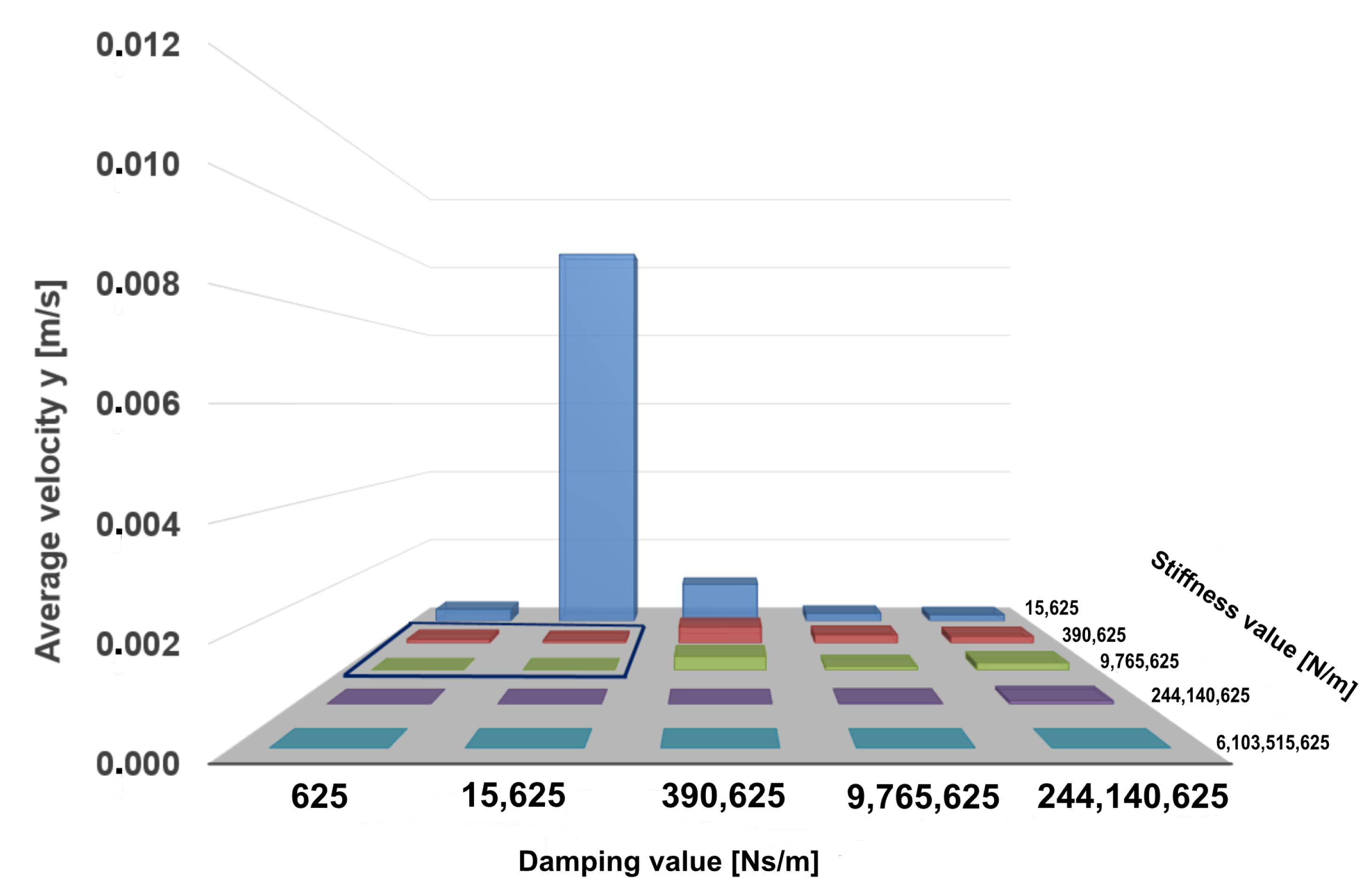
The maximum and the average screw velocities are shown in Figure 7 and Figure 8. From the presented results it can be seen that the highest velocity values are reached by the screw with a relatively small stiffness term of 1.56 × 10 4 N/m and damping values d [ 6.25 × 10 4 Ns / m , 1.56 × 10 4 Ns / m , 3.91 × 10 4 Ns / m ] . The maximum screw velocity of y ˙ m a x = 1.60 × 10 2 m/s is achieved with a parameter combination of c = 1.56 × 10 4 N/m and d = 1.56 × 10 4 Ns/m.
The deviations of the maximum screw velocity from its average values are comparatively greater than those shown in the case of screw displacement. When the stiffness term increases from 3.91 × 10 5 Ns/m up to 6.10 × 10 9 N/m, and for damping terms up to 3.91 × 10 4 Ns/m, the maximum velocity deviates further from its average values than in any other parameter sets.
Another parameter that was analyzed within the scope of this study was the time needed for the system to reach a static equilibrium. For the determination of the equilibrium state the velocity of the screw was compared in each time step until the simulation’s end. We considered the rest state to be reached from the point the velocity of the screw was continuously smaller then the pre-defined constraint ϵ y ˙ t . As shown in Figure 9, no equilibrium state could be reached when damping values dominated stiffness coefficients. The only exceptions were the simulation runs with the maximum damping term of d = 2.44 × 10 8  Ns/m, where the system could reach the rest state in the very short time of 2 × 10 5 s. The same model behavior was observed for large stiffness values of c = 2.44 × 10 8 N/m and c = 6.10 × 10 9 N/m.
The obtained results show that high stiffness and damping values guarantee reaching the screw equilibrium state. However, the goal of this study is to find the smallest values of the input model parameters that bring the screw into a resting state and do not violate the translational constraint m a x ( y ) < ϵ y . Therefore, the Region of Interest (RoI) for the fine-grained parameter search was chosen to be c { 3.91 × 10 5 N/m, …, 9.77 ×   10 6 N/m} and d {0 Ns/m, …, 1.56 ×   10 4 Ns/m}.
With the initial set of parameters, the search for the general influence of the stiffness and damping parameter was analyzed and the RoI was defined. We determined the RoI analytically by comparing the model translation, its velocity and the time it took to reach equilibrium. Since our goal was to find the minimum damping and stiffness coefficients that fit the requirements from Equation (2), the selected RoI was defined by its boundaries: c l o w e r = 3.91 × 10 5 N/m, c u p p e r = 9.77 × 10 6 N/m and d l o w e r = 0 Ns/m and d u p p e r = 1.56 × 10 4 Ns/m. The RoI is highlighted in Figure 5, Figure 6 and Figure 7 , and in Figure 8 and Figure 9 with a blue border.
After the RoI was determined, the optimal parameters for c and d could be found using a binary search method in order to reduce long computing times in cases when the parameters values would be determined linearly within the selected RoI. In the current implementation of the binary search we monitored the simulation outcome in each loop iteration in order to find the aforementioned smallest c and d, which had a significant impact on the screw translation and velocity. When at least one set of parameters was found and no changes were indicated in the model response for two consecutive parameter pairs, the search was stopped.
The results of the parameter determination using a binary search method are presented in Figure 10, where the distribution of stiffness and damping values with regard to screw translation is pictured. It can be observed that for the damping values d < 7813 Ns/m the majority of identified stiffness coefficients are distributed between 6 ×   10 5  N/m and 9 ×   10 5  N/m. Within this parameter interval the maximum screw displacement of 6.78  ×   10 4  m was reached. Through the combination of damping value d = 7813 Ns/m with the stiffness coefficient c 9 × 10 5 N/m very small screw displacements of up to 2.6 × 10 4 m could be achieved.
Another observation is that the screw displacement data perfectly fit a curve defined by the third-order polynomial equation:
δ = r + s × x + q × x 2 + u × x 3 ,
where δ (m) is a screw displacement, x (N/m) is the stiffness value and the following regression coefficients are r 0.002 (m), s 3.0 × 10 9 (m2/N), q 2.139 × 10 15 (m3/N2) and u 5.4 × 10 22 (m4/N3). The suitable fit of the regression curve shows a strong relationship between the stiffness term and screw translation. Using the determined parameters of the regression curve and a given stiffness value x, the screw displacement δ can be estimated along the selected RoI.
In order to determine the final set of parameters, we consider the screw displacement values that are on or below the purple line, which represents the translation constraint ϵ y . It is evident that a stiffness value of c = 823,224 N/m and a damping value of d = 488 Ns/m are found to be an optimal parameter pair, for which the sufficient maximum screw translation of 5.0 × 10 4 m is reached.
We now look at simulation outcomes in terms of the maximum screw velocities as shown in Figure 11. The maximum allowed velocity constraint from Table 2 is represented in the plot by a purple line. It can be seen that for the damping values d 7813 Ns/m the corresponding stiffness coefficients that are sufficient to hold the pre-defined constraints are distributed in the interval of c > 7.5 × 10 5 N/m and c < 1.6 × 10 6 N/m. Although the lowest screw velocity, which is marked red in the figure, is achieved at damping d = 7813 Ns/m and stiffness c = 1,562,499 N/m, the pair of minimum parameters is decided to be c = 823,224 N/m and d = 488 Ns/m, which supports the above statement concerning the optimal parameter set found with regard to maximum screw translation. The maximal velocity for optimal c and d is highlighted in dark blue.
The results from Figure 11 show that velocity data points fit the separate regression curve for each damping term by applying the same polynomial from Equation (3) with different r , s , q , u coefficients. In order to estimate the screw velocity, the stiffness term itself is not enough; the damping term also has to be considered.
The time at which the screw reaches the static equilibrium state is plotted in Figure 12. The shortest time of 0.07674 s to reach the equilibrium state is guaranteed by c = 823,224 N/m and d = 488 Ns/m and is highlighted by the blue frame. By applying the highest parameter values of d = 7813 Ns/m and c = 1,562,499 N/m to the model, the screw enters the rest state in 0.07908 s time, which is marked red in the plot.
The average CPU time per simulation was 5 s.

4. Discussion

A basic requirement for a valid model is the adequate definition of model input parameters. Because model parameters are generally vague, their predictive power is frequently questioned [35]. A comprehensive sensitivity analysis is essential in order to stand firmly against these sensible critical arguments. Therefore, the aim of this study was the development of a sensitivity analysis method to identify valid input parameters for a highly simplified rigid body model composed of an implant screw and vertebral body C4. For this purpose, a two-step sensitivity analysis was developed and applied to solve the parameter optimization problem: in the first step, the initial set of the stiffness and damping coefficients was created and a model simulation for each pair of the parameter values was performed. Based on the obtained simulation results, the region of interest for further parameter search was determined. In the final step, the binary search with constraint checking was utilized in order to define the minimal input parameter values. The resulting optimal model parameters were found to be c = 823,224 N/m for the stiffness value and d = 488 Ns/m for the damping value. Parameters smaller than those presented here were not analyzed, as they did not indicate any significant change in neither screw velocity nor screw translation.
In the case of a specific simulation scenario in which the input parameters are unavailable in the literature, and no possibility to conduct an experiment is given, the proposed method can be applied. Additionally, the obtained results can be used in more complex MBS and FE studies as valid model parameters for models of the different spinal regions featuring different degrees of abstraction.
There are some limitations to this study, which can be divided into two categories: model-related limitations and sensitivity-analysis-related limitations. The model-related limitation of the current model configuration is that only the elasticity in the longitudinal direction of the screw has been taken into account. However, in real scenarios, forces along the transverse and sagittal axes could also influence the screw. Furthermore, only the transnational movement was examined. However, if one wants to capture the entire mechanical behavior between bone and screw, torques must also be taken into account, as they can act on the screw when present during load. Therefore, the elasticity of the “implant screw–bone” combination will be taken into account in future work and analyzed in all spatial directions for both transnational and rotational movements.
Another model-related limitation is that the specific mass properties of a certain screw are included as model parameters that can influence the biomechanical behavior of the system. The analysis of the effects of mass properties such as mass, center of mass and inertia tensors on the model mechanics would provide further insight about the dependencies of the model parameters. The effects of variations in mass properties will be investigated in a future study.
The major sensitivity analysis limitation of the proposed approach is related to the search method used in order to find the optimal input parameters. Although the binary search operation has been shown to be an effective method for finding the optimal parameters, it depends on the quality of the previously selected RoI. Consequently, it is important to define an adequate RoI, which possesses the desired behavior of the screw regarding its translation and velocity. In the proposed approach, the boundaries of the RoI were selected manually by considering the results of the sensitivity analysis. However, this step can be automated by comparing simulation outcomes and defining the conditions that describe the RoI, which shall be considered in a future work. Another limitation of the binary search is that the function it is applied to needs to be monotonic. In our case, the monotonicity of the simulation function is given by the nature of the screw force in Equation (2).
Furthermore, we plan to expand the method by introducing parameters so that the patient-specific bone density is taken into account.
Despite the listed limitations, this study confirms the possibility of using multibody simulation as an adequate method for determining and analyzing biomechanical parameters. It shows that a real scenario, in this case a screw pullout test, could be reproduced by means of an MBS model and that the simulation results concur with the experimental results. Furthermore, we used our proposed method to demonstrate how sensitivity analysis can be used to define optimal model parameters.
In conclusion, this analysis should be seen as a part of our longstanding research focus. An MBS model of the spine is continuously being developed for the interactive advance planning of operative interventions. Our idea is to develop a tool based on a patient-specific MBS model to make preoperative patient-specific statements about the load situation. Furthermore, in contrast to FE simulations, the short computing times of the MBS models open up the possibility of simulating dynamic processes, and thus analyzing the stress of the spinal structures during a patient’s daily activities.
In the systematic literature review of Alizadeh et al. [36], concerning the biomechanical musculoskeletal models of the cervical spine, it is described that the dynamic MBS seems more suitable to investigate the risk of injuries to the cervical spine in connection with occupational environments or effects, because of the lack of dynamic loading in the FE models. Despite existing knowledge on the load situation of spinal structures, which is provided by sophisticated FE model structures, the basic load transfer behavior during dynamic movements remains initially unknown. Therefore, a holistic approach is warranted to close this knowledge gap in the future. The aim is to create MBS models of the entire human body with a finely structured spinal model, with which stresses within spinal structures can be analyzed during movements in daily life. With this approach new insights into the influences of an inserted implant on the human body during dynamic scenarios can be obtained. The parameter search method proposed in this study can be used to define the unknown biomechanical parameters describing the characteristics of spinal structures, as well as implants, especially in cases when conducting in vivo experiments is impossible.

Author Contributions

Conceptualization: I.K. and S.B.; Data curation: I.K. and S.B.; Formal analysis: I.K. and S.B.; Investigation: I.K. and S.B.; Methodology: I.K. and S.B.; Project administration: S.B.; Resources: I.K. and S.B.; Software: I.K.; Supervision: S.B.; Validation: I.K. and S.B.; Visualization: I.K. and S.B.; Writing—original draft: I.K. and S.B.; Writing—review & editing: I.K. and S.B. All authors have read and agreed to the published version of the manuscript.

Funding

This research received no external funding.

Institutional Review Board Statement

Not applicable.

Informed Consent Statement

Not applicable.

Data Availability Statement

Not applicable.

Acknowledgments

We would like to thank Claus Wenzler for fruitful discussions, as well as providing data sets and corresponding material information.

Conflicts of Interest

The authors declare no conflict of interest.

Abbreviations

The following abbreviations are used in this manuscript:
MBSmultibody simulation
FEfinite element
ATPSanterior transpedicular screw
BMDbone mineral densities
ASCFankylosing spondylitis cervical spine fractures
AVBSartificial vertebral body system
ASPSanterior screw plate system
SAsensitivity analysis

Appendix A. Pseudo-Code

Algorithm A1 Binary search for parameter optimization.
Input: c s t a r t , c e n d , d s t a r t , d e n d
Output: c m i n , d m i n
1:
while do d s t a r t < d e n d
2:
     d m i d = d e n d d s t a r t 2
3:
    Set new lower bound for d: d s t a r t = d m i d + 1
4:
    while  do c s t a r t < c e n d
5:
         c m i d = c e n d c s t a r t 2
6:
        Run model simulation: Y , Y ˙ , Y ¨ = f ( c m i d , d m i d ) (Equation (2))
7:
        Check model equilibrium state: equilibReached = checkRest( Y , Y ˙ , Y ¨ )
8:
        if  m a x ( Y ) ϵ y AND m a x ( Y ˙ ) ϵ y ˙ AND e m a x ( Y ˙ ) ϵ y ¨ e q  then
9:
           if equilibReached is TRUE then
10:
                c m i n = c m i d
11:
                d m i n = d m i d
12:
               Return c m i n , d m i n
13:
           end if
14:
        else
15:
           Set new lower bound for c: c s t a r t = c m i d + 1
16:
        end if
17:
    end while
18:
end while

References

  1. Wu, W.; Chen, C.; Ning, J.; Sun, P.D.; Zhang, J.; Wu, C.; Bi, Z.; Fan, J.; Lai, X.; Ouyang, J. A Novel Anterior Transpedicular Screw Artificial Vertebral Body System for Lower Cervical Spine Fixation: A Finite Element Study. J. Biomech. Eng. 2017, 139, 061003. [Google Scholar] [CrossRef] [PubMed]
  2. Naoum, S.; Vasiliadis, A.V.; Koutserimpas, C.; Mylonakis, N.; Kotsapas, M.; Katakalos, K. Finite Element Method for the Evaluation of the Human Spine: A Literature Overview. J. Funct. Biomater. 2021, 12, 43. [Google Scholar] [CrossRef] [PubMed]
  3. Rosa, G.L.; Clienti, C.; Mineo, R.; Audenino, A. Experimental analysis of pedicle screws. Procedia Struct. Integr. 2016, 2, 1244–1251. [Google Scholar] [CrossRef] [Green Version]
  4. Koktekir, E.; Toktas, Z.O.; Seker, A.; Akakin, A.; Konya, D.; Kilic, T. Anterior transpedicular screw fixation of cervical spine: Is it safe? Morphological feasibility, technical properties, and accuracy of manual insertion. J. Neurosurg. Spine 2015, 22, 596–604. [Google Scholar] [CrossRef] [Green Version]
  5. Reitman, C.; Nguyen, L.; Fogel, G. Biomechanical evaluation of relationship of screw pullout strength, insertional torque, and bone mineral density in the cervical spine. J. Spinal Disord. Tech. 2004, 17, 306–311. [Google Scholar] [CrossRef] [Green Version]
  6. Koller, H.; Acosta, F.; Tauber, M.; Fox, M.; Hudelmaier, M.; Forstner, R.; Augat, P.; Penzkofer, R.; Pirich, C.; Kässmann, H.; et al. Cervical anterior transpedicular screw fixation (ATPS)—Part II. Accuracy of manual insertion and pull-out strength of ATPS. Eur. Spine J. 2008, 17, 539–555. [Google Scholar] [CrossRef] [Green Version]
  7. Becker, Y.N.; Motsch, N.; Hausmann, J.; Breuer, U.P. Hybrid composite pedicle screw—finite element modelling with parametric optimization. Inform. Med. Unlocked 2020, 18, 100290. [Google Scholar] [CrossRef]
  8. Mas, Y.; Gracia, L.; Ibarz, E.; Gabarre, S.; Pena, D.; Herrera, A. Finite element simulation and clinical follow-up of lumbar spine biomechanics with dynamic fixations. PLoS ONE 2017, 12, 1–19. [Google Scholar]
  9. Schmidt, H.; Heuer, F.; Wilke, H.J. Which axial and bending stiffnesses of posterior implants are required to design a flexible lumbar stabilization system? J. Biomech. 2009, 42, 48–54. [Google Scholar] [CrossRef]
  10. Goel, V.K.; Grauer, J.; Patel, T.; Biyani, A.; Sairyo, K.; Vishnubhotla, S.; Matyas, A.; Cowgill, I.; Shaw, M.; Long, R.; et al. Effects of Charite artificial disc on the implanted and adjacent spinal segments mechanics using a hybrid testing protocol. Spine 2005, 30, 2755–2764. [Google Scholar] [CrossRef]
  11. Sun, J.; Wang, Q.; Cai, D.; Gu, W.; Ma, Y.; Sun, Y.; Wei, Y.; Yuan, F. A lattice topology optimization of cervical interbody fusion cage and finite element comparison with ZK60 and Ti-6Al-4V cages. BMC Musculoskelet. Disord. 2021, 22, 390. [Google Scholar] [CrossRef] [PubMed]
  12. Galbusera, F.; Bellini, C.M.; Costa, F.; Assietti, R.; Fornari, M. Anterior cervical fusion: A biomechanical comparison of 4 techniques: Laboratory investigation. J. Neurosurg. Spine SPI 2008, 9, 444–449. [Google Scholar] [CrossRef] [PubMed]
  13. Liu, S.; Qi, W.; Zhang, Y.; Wu, Z.; Yan, Y.B.; Lei, W. Effect of bone material properties on effective region in screw-bone model: An experimental and finite element study. BioMed. Eng. Online 2014, 13, 83. [Google Scholar] [CrossRef] [PubMed] [Green Version]
  14. Van den Abbeele, M.; Valiadis, J.M.; Lima, L.V.; Khalifé, P.; Rouch, P.; Skalli, W. Contribution to FE modeling for intraoperative pedicle screw strength prediction. Comput. Methods Biomech. Biomed. Eng. 2018, 21, 13–21. [Google Scholar] [CrossRef]
  15. Qi, W.; Yan, Y.B.; Zhang, Y.; Lei, W.; Wang, P.; Hou, J. Study of stress distribution in pedicle screws along a continuum of diameters: A three dimensional finite element analysis. Orthop. Surg. 2011, 3, 57–63. [Google Scholar] [CrossRef]
  16. Matsukawa, K.; Yato, Y.; Imabayashi, H. Impact of Screw Diameter and Length on Pedicle Screw Fixation Strength in Osteoporotic Vertebrae: A Finite Element Analysis. Asian Spine J. 2021, 15, 566–574. [Google Scholar] [CrossRef]
  17. Sensale, M.; Vendeuvre, T.; Schilling, C.; Grupp, T.; Rochette, M.; Dall’Ara, E. Patient-Specific Finite Element Models of Posterior Pedicle Screw Fixation: Effect of Screw’s Size and Geometry. Front. Bioeng. Biotechnol. 2021, 9, 175. [Google Scholar] [CrossRef]
  18. Xu, M.; Yang, J.; Lieberman, I.H.; Haddas, R. Finite element method-based study of pedicle screw–bone connection in pullout test and physiological spinal loads. Med. Eng. Phys. 2019, 67, 11–21. [Google Scholar] [CrossRef]
  19. Su, K.C.; Chen, K.H.; Pan, C.C.; Lee, C.H. Biomechanical Evaluation of Cortical Bone Trajectory Fixation with Traditional Pedicle Screw in the Lumbar Spine: A Finite Element Study. Appl. Sci. 2021, 11, 583. [Google Scholar] [CrossRef]
  20. Somtua, C.; Aroonjarattham, P.; Aroonjarattham, K. Parametric study of pedicle screw: Effect of stress transfer parameters on pullout strength. Asia-Pac. J. Sci. Technol. 2021, 26, 1–11. [Google Scholar] [CrossRef]
  21. Ritddech, S.; Aroonjarattham, P.; Aroonjarattham, K. The Effect of Screw Parameters on Pullout Strength of Screw Fixation in Cervical Spine. Int. J. Mech. Mechatron. Eng. 2015, 9, 247–250. [Google Scholar]
  22. Bauer, S. Basics of Multibody Systems: Presented by Practical Simulation Examples of Spine Models. In Numerical Simulation; Lopez-Ruiz, R., Ed.; IntechOpen: London, UK, 2016; Chapter 2. [Google Scholar] [CrossRef] [Green Version]
  23. Bonnheim, N.; Keaveny, T. Load-transfer in the human vertebral body following lumbar total disc arthroplasty: Effects of implant size and stiffness in axial compression and forward flexion. JOR Spine 2020, 3, e1078. [Google Scholar] [CrossRef] [PubMed] [Green Version]
  24. Pezowicz, C.; Filipiak, J. Influence of loading history on the cervical screw pullout strength value. Acta Bioeng. Biomech. 2009, 11, 35–40. [Google Scholar]
  25. Qiao, G.; Rahmatalla, S. Identification of damping and stiffness parameters of cervical and lumbar spines of supine humans under vertical whole-body vibration. J. Low Freq. Noise Vib. Act. Control. 2020, 39, 59–71. [Google Scholar] [CrossRef] [Green Version]
  26. Silvestros, P.; Preatoni, E.; Gill, H.S.; Gheduzzi, S.; Hernandez, B.A.; Holsgrove, T.P.; Cazzola, D. Musculoskeletal modelling of the human cervical spine for the investigation of injury mechanisms during axial impacts. PLoS ONE 2019, 14, e0216663. [Google Scholar]
  27. Kassem, A.; Sameh, A. Lumbar Spine: Parameter Estimation for Realistic Modeling. WSEAS Trans. Theor. Appl. Mech. 2007, 2, 113–118. [Google Scholar]
  28. Rohlmann, A.; Zander, T.; Bergmann, G.; Boustani, H.N. Optimal stiffness of a pedicle-screw-based motion preservation implant for the lumbar spine. Eur. Spine J. 2012, 21, 666–673. [Google Scholar] [CrossRef] [Green Version]
  29. Au-Yeung, K.Y.; Yang, B.; Sun, L.; Bai, K.; Yang, Z. Super Damping of Mechanical Vibrations. Sci. Rep. 2019, 9, 17793. [Google Scholar] [CrossRef]
  30. Zhang, Q.H.; Tan, S.H.; Chou, S.M. Effects of bone materials on the screw pull-out strength in human spine. Med. Eng. Phys. 2006, 28, 795–801. [Google Scholar] [CrossRef]
  31. Goldsmith, C.; Gafni, A.; Drummond, M.; Torrance, G.; Stoddart, G. Sensitivity Analysis and Experimental Design: The Case of Economic Evaluation of Health Care Programmes. In Proceedings of the Third Canadian Conference on Health Economics, Winnipeg, MB, Canada, 2 May 1986. [Google Scholar]
  32. Saltelli, A.; Chan, K.; Scott, E. Sensitivity Analysis; Wiley: Hoboken, NJ, USA, 2009. [Google Scholar]
  33. Özkaya, N.; Leger, D.; Goldsheyder, D.; Nordin, M. Fundamentals of Biomechanics: Equilibrium, Motion, and Deformation; Springer: Berlin/Heidelberg, Germany, 2016. [Google Scholar]
  34. Knuth, D.E. Optimum binary search trees. Acta Inform. 1971, 1, 14–25. [Google Scholar] [CrossRef]
  35. Zander, T.; Dreischarf, M.; Timm, A.K.; Baumann, W.W.; Schmidt, H. Impact of material and morphological parameters on the mechanical response of the lumbar spine—A finite element sensitivity study. J. Biomech. 2017, 53, 185–190. [Google Scholar] [CrossRef] [PubMed]
  36. Alizadeh, M.; Knapik, G.G.; Mageswaran, P.; Mendel, E.; Bourekas, E.; Marras, W.S. Biomechanical musculoskeletal models of the cervical spine: A systematic literature review. Clin. Biomech. 2020, 71, 115–124. [Google Scholar] [CrossRef] [PubMed]
Figure 1. Different views of the screw fixed in C4 vertebra: lateral view of vertebra C4 with implemented screw (cross section) (A) and semi-top and lateral view of the screw–vertebra model (B).
Biomechanics 02 00011 g001
Figure 2. Attachment point of the lower anchor screw of the vertebral body replacement implants to the endplate of the 4th cervical vertebra (A). Representation of the screw diameter (B). Location of Center of Gravity (CG) and application point of the pullout force Fpull of the anchor screw (C).
Biomechanics 02 00011 g002
Figure 3. Comparison of the simulation result and experimental result of Pezowicz et al. [24]: The results of the simulation are shown by the blue solid line and those of the experiment by the red dashed line.
Biomechanics 02 00011 g003
Figure 4. Workflow of the proposed parameter search: in the first step of the pipeline two initial sets of parameters (C and D) are collected. For each pair of parameter values the model simulation is executed and the final search intervals for c and d are determined. In the final step a binary search is used for the parameter minimization.
Biomechanics 02 00011 g004
Figure 5. Maximum screw translation calculated for the initial parameters set with applied pullout force of 411 N. The region of interest for c { 3.91 × 10 5 N/m, …, 9.77 × 10 6 N/m N/m and d {0 Ns/m, …, 1.56 × 10 4 Ns/m} is shown by a blue frame.
Biomechanics 02 00011 g005
Figure 6. Average screw translation calculated for the initial parameters set with applied pullout force of 411 N. The region of interest for c { 3.91 × 10 5 N/m, …, 9.77 × 10 6 N/m} N/m and d {0 Ns/m, …, 1.56 × 10 4 Ns/m} is shown by a blue frame.
Biomechanics 02 00011 g006
Figure 7. Maximum screw velocity calculated for the initial parameters set with an applied pullout force of 411 N. The region of interest for c { 3.91 × 10 5   N / m , , 9.77 × 10 6   N / m } and d { 0 Ns / m , , 1.56 × 10 4 Ns / m } is framed in blue.
Biomechanics 02 00011 g007
Figure 8. Average screw velocity calculated for the initial parameters set with applied pullout force of 411 N. The region of interest for c { 3.91 × 10 5 N / m , , 9.77 × 10 6 N / m } and d { 0 Ns / m , , 1.56 × 10 4 Ns / m } is framed in blue.
Biomechanics 02 00011 g008
Figure 9. Time of reaching static equilibrium calculated for the initial parameters set with applied pullout force of 411 N. The region of interest for c { 3.91 × 10 5 N/m, …, 9.77 ×   10 6 N/m} and d { 0 Ns/m, …, 1.56 ×   10 4 Ns/m} is shown by a blue frame. For the value pairs stiffness and damping, for which no colored area can be seen at the corresponding point, a state of equilibrium was not reached.
Biomechanics 02 00011 g009
Figure 10. Result of the parameter optimization using binary search: the maximum screw translation values are given for different selected damping and stiffness values. The curves connecting data points represent the corresponding regression curves. Screw displacement for optimal parameters is marked using the blue frame.
Biomechanics 02 00011 g010
Figure 11. Results of parameter optimization using binary search: Maximum screw velocity values are given for different damping and stiffness values. Curves connecting data points represent corresponding regression curves. The optimum stiffness value selected by the presented approach is framed in blue. Red is used to mark the stiffness value and the corresponding damping value that cause the lowest maximum screw velocity.
Biomechanics 02 00011 g011
Figure 12. Result of parameter optimization using binary search: time the screw needs to reach a static equilibrium state for different damping and stiffness values.
Biomechanics 02 00011 g012
Table 1. Mass properties of the anchor screw.
Mass PropertiesValue
mass [g]0.29
CG x [mm]0
CG y [mm]−7.03
CG z [mm]0.0
main axis of inertia tensor in respect to CoM Ix [g·mm2](1.0/0.00/0.00)
main axis of inertia tensor in respect to CoM Iy [g·mm2](0.00/0.96/0.28)
main axis of inertia tensor in respect to CoM Iz [g·mm2](0.00/−0.28/0.96)
screw length [mm]17.0
screw diameter [mm]2.7
Table 2. Thresholds applied to the parameter search: the values were obtained empirically so that the computing time for the search was optimized.
Constraint DefinitionNotationValue
Threshold for screw translation [m] in y-direction ϵ y 5 × 10 4
Threshold for screw velocity [m/s] ϵ y ˙ 5 × 10 5
Threshold for screw velocity in equilibrium state [m/s] ϵ y ˙ e 5 × 10 8
Threshold for screw acceleration in equilibrium state [m/s2] ϵ y ¨ e 5 × 10 9
Publisher’s Note: MDPI stays neutral with regard to jurisdictional claims in published maps and institutional affiliations.

