Article

Investigating Kinematics and Electromyography Changes in Manual Handling Tasks with an Active Lumbar Exoskeleton

1
UMR CNRS 7338 BioMécanique et BioIngénierie, Université de Technologie de Compiègne (UTC), 60200 Compiègne, France
2
Japet Medical Devices, 59120 Loos, France
3
Faculté des Sciences du Sport, Université Paris-Saclay, 91190 Gif-sur-Yvette, France
4
Faculté des Sciences du Sport, Université de Poitiers, 86073 Poitiers, France
5
Centre Hospitalier de Maubeuge, 59600 Maubeuge, France
6
ULR 7369—URePSSS—Unité de Recherche Pluridisciplinaire Sport Santé Société, Université de Lille, 59000 Lille, France
*
Author to whom correspondence should be addressed.
Biomechanics 2024, 4(2), 357-368; https://doi.org/10.3390/biomechanics4020025
Submission received: 4 March 2024 / Revised: 16 May 2024 / Accepted: 24 May 2024 / Published: 4 June 2024
(This article belongs to the Section Tissue and Vascular Biomechanics)

Abstract

:
Companies are becoming increasingly aware of the health of their employees and are now integrating exoskeleton solutions for both prevention and job maintenance. However, the effect of using exoskeletons is still an open question. Therefore, this study aimed to evaluate the impact of an active lumbar exoskeleton and its passive belt on trunk kinematics and muscle activity using instrumented motion analysis. Twenty-three healthy subjects volunteered to perform three handlings of a 5 kg load (free lifting, squat lifting, and load transfer) under three different experimental conditions. The “Control” condition was when the subject did not wear any device, the “Belt” condition was when the subject wore only the passive part of the exoskeleton, and the “Exo” condition was when the subject wore the active exoskeleton. Based on the Rapid Upper Limb Assessment scale, the exoskeleton reduced the time spent in angles that were considered dangerous for the back, according to ergonomic evaluations. Furthermore, for the handling sessions, it was observed that the exoskeleton did not modify muscle activity in the abdominal–lumbar region.

1. Introduction

Musculoskeletal disorders (MSDs) can affect the joints, muscles, and tendons and are often related to professional activity [1]. Work-related factors can contribute to the onset, duration, and worsening of MSDs, which may eventually lead to sick leaves or the need for professional reorientation. Consequently, managing and preventing MSDs has become a major challenge for the companies concerned [2]. In France, MSDs account for 87% of occupational diseases, and back pain accounts for 20% of accidents at work, which can lead to serious aftereffects with the risk of professional exclusion. In addition, it has a very high cost for companies, amounting to nearly two billion euros in 2017 [2]. For several years, studies have been conducted on MSD risk factors, highlighting two types of risk factors in companies: physical factors (excessive repetitive movements, heavy lifting, awkward postures, etc.) and psychosocial factors (lack of social support, high psychosocial work demand, lack of autonomy, etc.) [3]. In this context, the utilization of exoskeletons has been advocated to reduce work-related musculoskeletal stress [4].
More precisely, the back is the area most affected by musculoskeletal stress in various industries, i.e., construction [4], nursing [5], farming [6], and manufacturing [7]. In this context, the utilization of exoskeletons has been advocated to reduce work-related musculoskeletal stress. Additionally, spinal traction devices offer opportunities for preventing low back pain [8]. However, designing lower-back exoskeletons with such spinal traction functions presents challenges in terms of potential side effects on adjacent levels, which could globally limit the efficiency of the exoskeleton [9].
Despite mechanization, automation, and ergonomic interventions aimed at reducing the occurrence and progression of musculoskeletal disorders [10], many industrial tasks require human mobility and the handling of loads [11,12]. The emergence of body-worn assistive devices called exoskeletons now entails the consideration of alternative solutions to relieve workers of musculoskeletal constraints [13]. The main objective of exoskeletons is to prevent injuries while maintaining the mobility of workers [14]. However, the daily use of exoskeletons in companies has raised questions about their direct effect or transparency [15], defined as their neutrality of biomechanical impact on humans [16,17] in terms of ranges of motion and the muscular activity of surrounding muscles [18]. Additionally, owing to the heterogeneity of exoskeleton designs, predicting physical human-exoskeleton interactions accurately to determine the appropriate prescription for use in industrial sectors requires specific investigation [19]. However, evaluating the effectiveness of industrial exoskeletons is a challenging issue [20,21]. Additionally, since an exoskeleton requires classification as a medical device by EU regulation (2017/745) [22], the rigorous evaluation of each active and passive component of the product is required [23]. This is particularly critical in the case of exoskeletons that combine active and passive components because a sophisticated control system is required to optimize performance and demonstrate the benefits of these designs [24].
Biomechanical research methods are commonly used to assess the impact of a device, training, or surgery on the body [25], and motion analysis is defined as a biomarker of the musculoskeletal system [26]. In human motion analysis studies, kinematics provides a quantitative approach to the motion, while muscle activity measurement by electromyography (EMG) is related to the forces that generated the motion [25]. In the context of pathologies or MSDs, motion analysis appears as a powerful decision-making tool [27] to quantify ability reduction or compensation strategy [28] and also could document the time spent at risk postures [29] based on the criteria of the Rapid Upper Limb Assessment (RULA) [30]. Consequently, kinematics and EMG are common to quantify the effect of the exoskeleton [31,32,33].
The objective of this study is to objectively quantify the biomechanical impact of an active lumbar exoskeleton. By conducting handling tasks in a motion capture laboratory and analysing kinematics and EMG data, we hypothesized that the active exoskeleton would influence the range of motion and modify the muscular activity of the trunk muscles. These two components are crucial for objectively categorizing the prescription for the future use of the active exoskeleton.

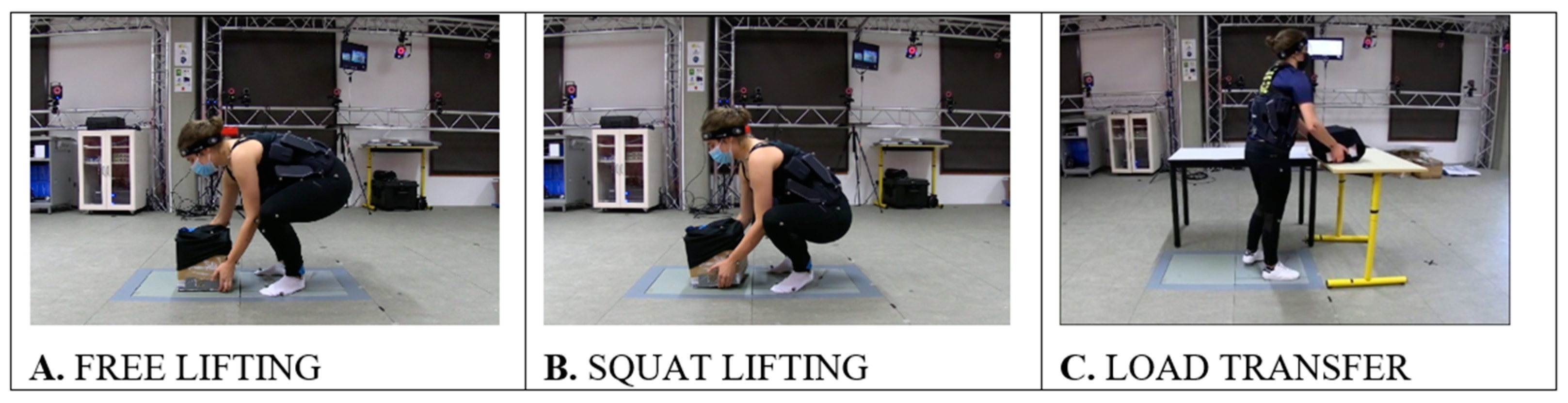
2. Materials and Methods

2.1. Exoskeleton

The exoskeleton used in this study was a lumbar ambulatory traction device (Japet.W, Japet Medical Devices©, Loos, France) [14]. It is designed to relieve lumbar strains [34] by applying a vertical traction force. The device consists of two sub-elements, a passive part with the textile belt and the active part with two series elastic actuators (SEA) sets positioned on both sides of the body (Figure 1A). These two parts are never employed in isolation.
The SEA is a compliant mechanism allowing a dynamic movement with an integrated damping for the comfort of the user [32]. An electronic system coupled with a mechanical transmission system allows the application of a lumbar traction force adjusted to the user’s desired setting (4 kg, 8 kg, 12 kg, or 16 kg). The SEA is connected to the belts by a ball joint, allowing them to adapt to the movement of the trunk.

2.2. Belt

The belt used is the passive part of the exoskeleton (textile belt) once SEAs are removed (Figure 1B). The upper and lower reels were retained to tighten the belt and adjust it to the trunk. This part is similar to a classic lumbar belt.

2.3. Population

Twenty-three healthy volunteers (fourteen women and nine men) participated in this study (age: 20.2 ± 1.2 years, mass: 67.7 ± 11.2 kg, height: 175.4 ± 9.9 cm) after signing a statement of informed consent to the experimental procedure in accordance with the Declaration of Helsinki.

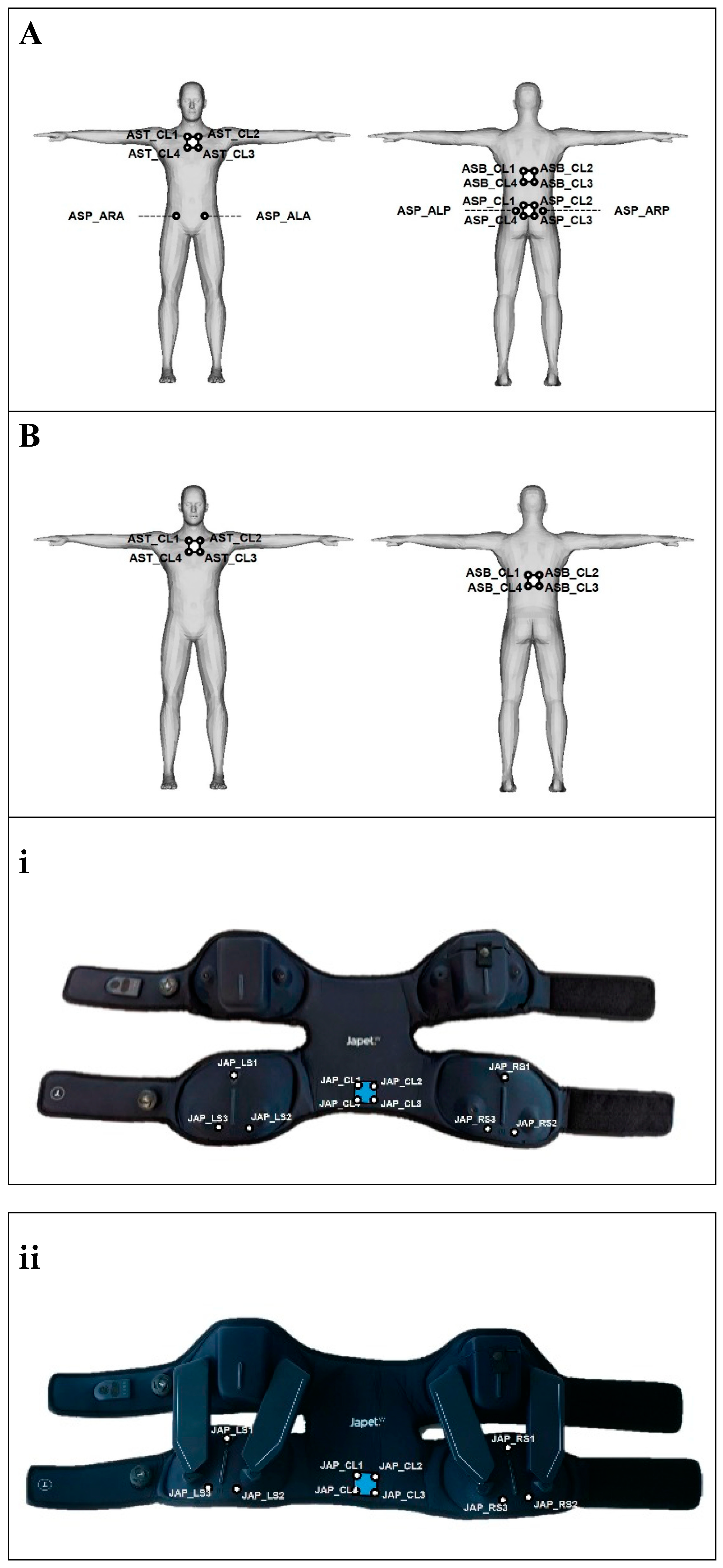
2.4. Instrumented Motion Capture Session and Data Pre-Processing

Three handling task sessions were recorded. The “FREE LIFTING” session consisted of symmetric lifting of a 5 kg load for which the subject was free to choose his lifting technique (Figure 2A). During the “SQUAT LIFTING” session, a 5 kg load was lifted while the subject had to bend their knees and keep their trunk straight (Figure 2B). The “LOAD TRANSFER” session consisted of moving a 5 kg load between two tables that were perpendicular to each other (Figure 2C).
Instrumented motion capture session was performed by 36 optoelectronic cameras (Vicon T160, Vicon Motion Systems Ltd., Oxford, UK) sampled to 200 Hz allowed to record 3D position of landmarks (Figure 3). Two body marker sets and two device marker sets were used [35]. The first body marker set was used to analyse the “Control” condition (Figure 3A). The combination of the second body marker set and the first device marker set was used to analyse the “Belt” condition (Figure 3B,i). Finally, the second body marker set combined with the second device marker set allowed the analysis of the “Exo” condition (Figure 3B,ii).
All acquisitions were 3D reconstructed and labelled with Nexus Software (Vicon Motion Systems Ltd., Oxford, UK). Three pairs of surface EMG electrodes (PICO, Cometa srl, Milan, Italy) sampled to 1000 Hz were located in the trunk muscles: Longissimus Dorsi (LD), Rectus Abdominis (RA), and Obliquus ExternusAbdominis (OE), according to the SENIAM recommendations [36]. The subjects’ skin was rubbed with abrasive paper and then cleaned with alcohol. The EMG sensor for the Longissimus Dorsi (LD) was placed 25 mm lateral to the L1 spine. The EMG sensor for the Rectus Abdominis (RA) was placed 25 mm above the umbilicus and 40 mm lateral to the midline. The EMG sensor for the Obliquus Externus Abdominis (OE) was placed 20 mm above and 20 mm anterior to the iliac crest [37]. Synchronized 3D coordinates of all markers and EMG data were exported from Nexus Software (Vicon Motion Systems Ltd., Oxford, UK) to a .csv file and processed directly on Matlab R2022a (The Mathworks Inc., Natick, MA, USA).

2.5. Data Analysis

2.5.1. Kinematics Data

The calibration phase allowed for the creation of an anatomical coordinate system for each body segment and its relationship with cluster markers [25]. The two body segments of interest in this study were anatomical pelvis segment associated with the reference frame R_pelvis and the thorax associated with the reference frame R_torso. Calculation of R_pelvis was based on the markers cluster {ASP_CL1, ASP_CL2, ASP_CL3, ASP_CL4} for the “Control” condition (Robertson et al. 2014) and {JAP_CL1, JAP_CL2, JAP_CL3, JAP_CL4} for the “Belt” and “Exo” conditions [38]. Calculation of R_torso is defined by the markers cluster [25] {AST_CL1, AST_CL2, AST_CL3, AST_CL4} for the three conditions. After the computation of the rotation matrix associated with the relative orientation of R_torso in the R_pelvis [25], flexion, lateral bending, and axial rotation angles were deduced [39].
To compare subjects performing handling tasks, the percentage of time spent in predefined angular ranges was analysed for the main rotation of the three movements [30]. The angular ranges were based on the RULA method [29] and were defined by {<−10°; [−10° 0°[; [0° 20°[; [20 60°[; ≥60°} for the flexion rotation angle and {<−20°; [−20° −10°[; [−10° 0°[; [0° 10°[; [10° 20°[; ≥20°} for the lateral bending and axial rotation angles. For FREE LIFTING and SQUAT LIFTING, only the flexion rotation angle was analysed [18,40].

2.5.2. EMG

The EMG data were analysed for all conditions for the handling simulation session (FREE LIFTING, SQUAT LIFTING, and LOAD TRANSFER). The root mean square (RMS) values of the EMG data were computed to evaluate the global muscle activity during the session [25]. RMS was calculated from the filtered EMG data thanks to a passband (4th order Butterworth) between 20 Hz and 500 Hz [41]. To normalize the RMS signal, the condition “Control” was taken as a reference, and each signal was divided by the maximum of the “Control” condition (MCC) for all records [42].

2.5.3. Statistical Analysis

For kinematics data, nonparametric Friedman tests were performed with all subjects’ percentages of time spent in each RULA area of the handling sessions of the 3 conditions “Control”, “Belt”, and “Exo”. The null hypothesis was no significance difference between the three conditions. The null hypothesis is rejected if the p-value (level of significance) of the Friedman test is less than 0.05. In this case, the alternative hypothesis (significant difference between the three conditions) was supported, and a post hoc test can be performed. As a post hoc test, a Wilcoxon test with set {αi, αj} with α as ROM for the Range of mobility session or the percentage of time spent in each RULA area of handling session, and i ϵ {Control, Belt, Exo} and j ϵ {Control, Belt, Exo}, i ≠ j was computed. For statistical analysis, we defined the null hypothesis as no significant difference between the conditions. The null hypothesis is rejected if the p-value of the Wilcoxon test is less than 0.05. In this case, the alternative hypothesis (significant difference between the two conditions) was supported.
For EMG data and all three conditions, statistical analysis was performed on the normalized RMS values, which are a good indicator of the magnitude of the muscle activity [25]. For all muscles, Friedman tests, as nonparametric tests, were performed with the set {RMSControli, RMSBelti, RMSExoi} with i ϵ {LLD, RLD, LRA, RRA, LOE, ROE}. The null hypothesis was no significant difference between the three conditions. The null hypothesis is rejected if the p-value (level of significance) of the Friedman test is less than 0.05. In this case, the alternative hypothesis (significant difference between the three conditions) was supported, and a post hoc test can be performed. As a post hoc test, a Wilcoxon test with set {RMSi, RMSj} with i ϵ {Control, Belt, Exo} and j ϵ {Control, Belt, Exo}, i ≠ j was computed. We performed the same statistical analysis as previously conducted.
All calculations were performed with MATLAB R2022a software.

3. Results

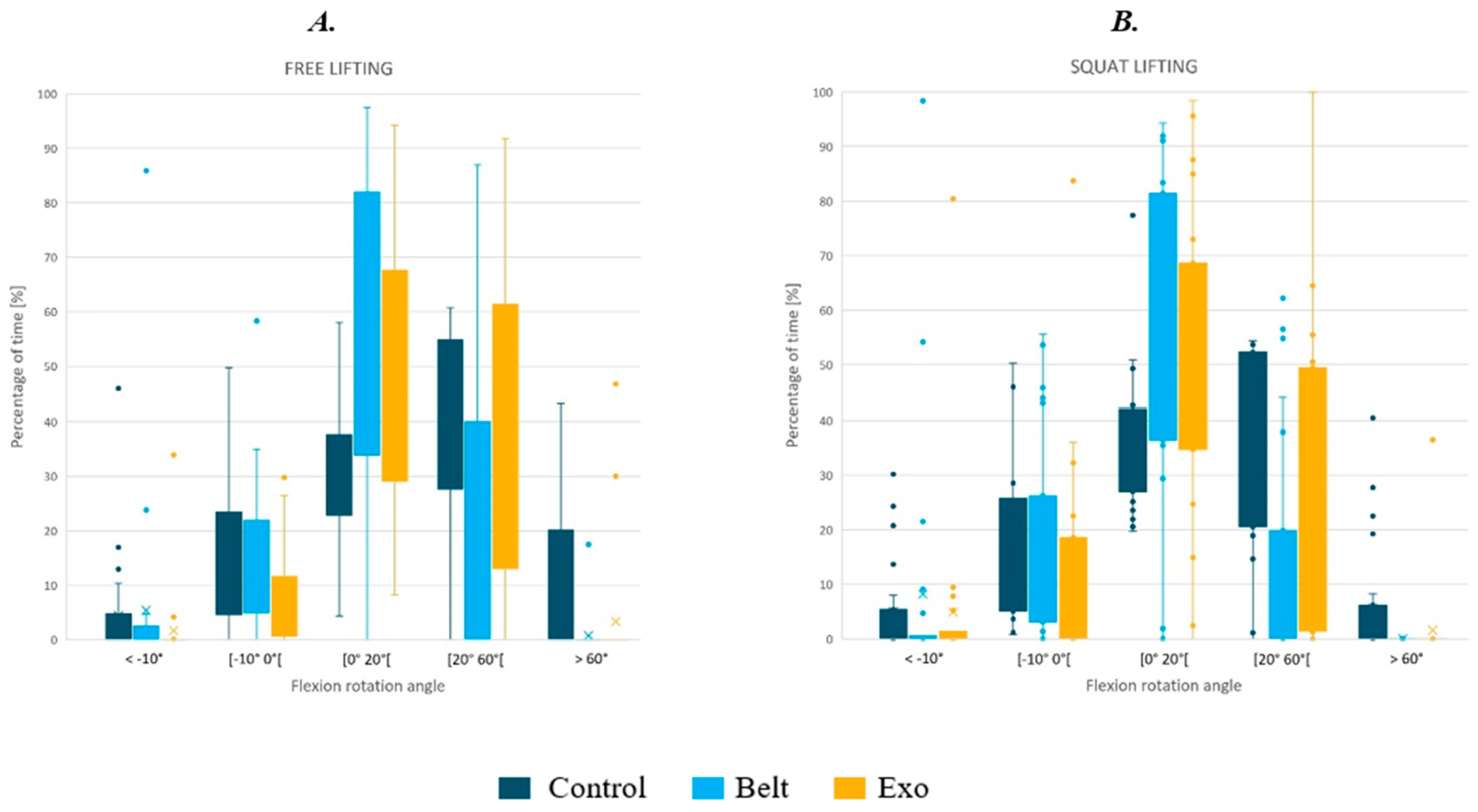
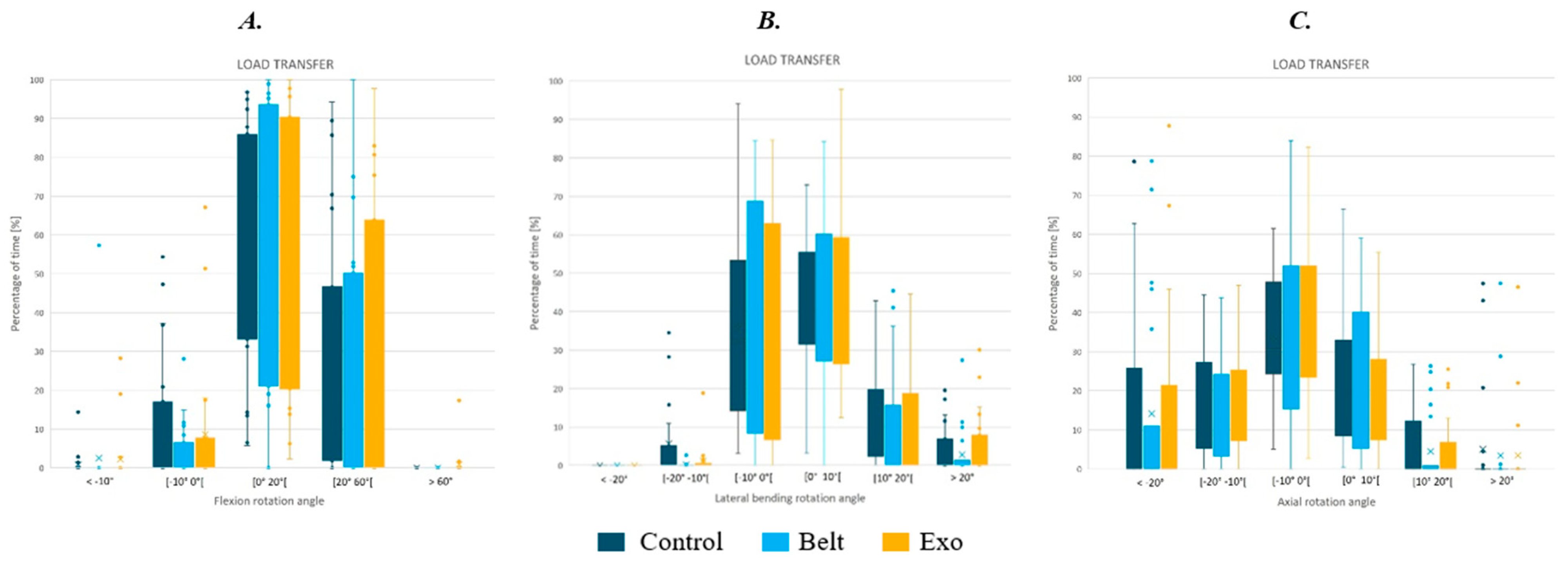
3.1. Kinematics Analysis
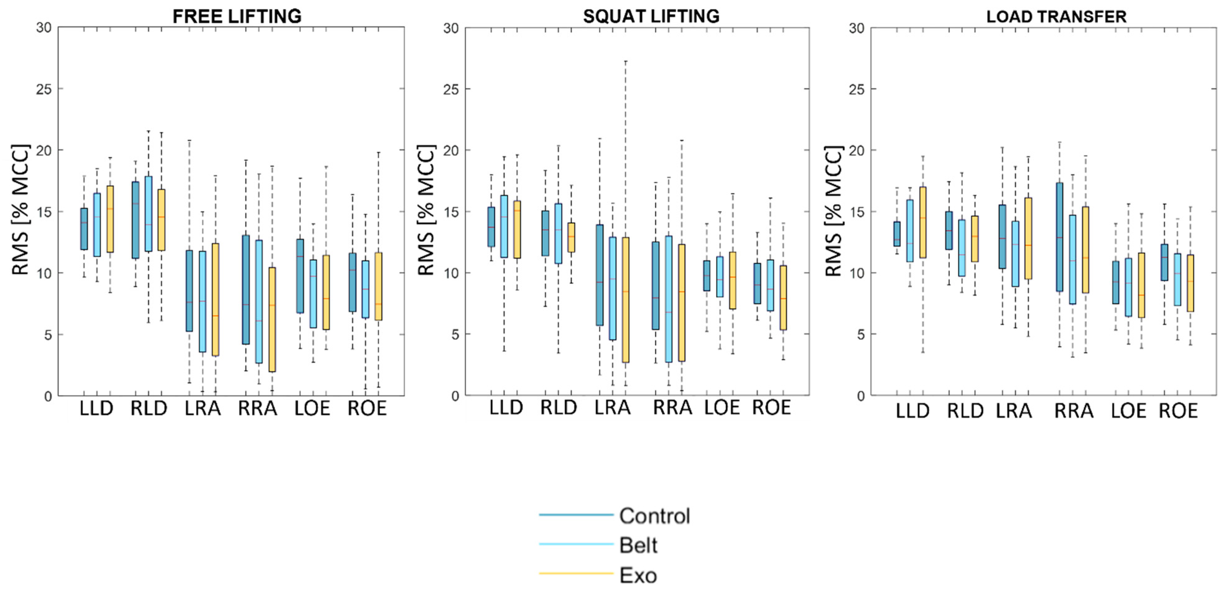
The following figure (Figure 4) represents the percentage of time spent in each RULA area for flexion rotation angle of sessions FREE LIFTING and SQUAT LIFTING under the three conditions (Control, Belt, and Exo).
We noticed the difference in the time spent in RULA areas for flexion rotation angle for the FREE LIFTING and the SQUAT LIFTING session according to the conditions (Control, Belt, Exo) confirmed by the Friedman test (Table 1).
Post hoc tests corroborate these observations (Table 2 and Table 3). Regarding the FREE LIFTING, the Belt tends to decrease the time spent >60° and increase the time spent in the area [0° 20°[ compared to the Control group. The Exo tends to decrease the time spent in extension (<0°) and in flexion >60° and increase the time spent in the area [0° 60°[. The same assessment can be made for the SQUAT LIFTING.
For the LOAD TRANSFER session, the percentage of time spent in each RULA area of flexion, lateral bending, and axial rotation angles was analysed (Figure 5).
For flexion rotation angle and axial rotation, we noticed no difference between conditions confirmed by the Friedman test. We observed only a significant difference in the lateral bending rotation angle of the LOAD TRANSFER session for the range [−20° −10[ and [10° 20°[ with a p-value of the Friedmann test of 3.55 × 10⁻⁵ and 0.0655, respectively. On the one hand, the Wilcoxon post hoc test concluded a difference for the two RULA areas between [−20° −10°[ and [10° 20°[ for Control vs. Belt with a p-value of 9.71 × 10⁻⁴ and 0.0272. On the other hand, the Wilcoxon post hoc test concluded only a significant difference for Control vs. Exo for the range [−20° −10°[ with a p-value of 0.0218.

3.2. EMG

The following figure (Figure 6) represents the RMS of the EMG of the six muscles recorded under the three conditions (Control, Belt, Exo) for the three handling sessions: ‘FREE LIFTING’, ‘SQUAT LIFTING’, and ‘LOAD TRANSFER’.
We noticed little difference in RMS values according to the conditions supported by the Friedman test for all muscles (Table 4).
However, these differences were not confirmed by post hoc tests. Consequently, according to these results we cannot conclude that the difference is statistically significant.

4. Discussion

The goal of this study was to quantify the biomechanical impact through the kinematics and muscle activity of an active lumbar exoskeleton. For this purpose, the exoskeleton was divided into a passive part (textile belt) and an active part (complete exoskeleton with SEA). During handling, our results showed that both the passive and active parts of the exoskeleton reduced the time spent in the risk range of motion, as defined by the RULA method [29]. The passive belt tends to greatly reduce the range of motion of flexion and lateral bending angles. Both devices seem to be transparent on muscle activity. These observations confirm our hypothesis on the kinematics but not on the level of muscle activity by the exoskeleton.
In contrast to the Belt condition, the active exoskeleton tested by the “Exo” condition maintains good trunk mobility while decreasing maximal amplitudes compared to the “Control” condition. Such results have already been observed for lumbar belts [43] and exoskeletons [41]. In fact, common lumbar belts were designed to increase back stability, which results in a reduced range of motion [43]. The current exoskeleton is composed of a passive part (textile belt) and an active part (complete exoskeleton with SEA). Our study demonstrates that the impact of the active part of the exoskeleton, tested during the Exo session, is to increase the range of motion in comparison with the “Belt” condition while preventing the possibility of extreme angles. In handling tasks, such extreme angle positions are known to increase the risk of musculoskeletal disorders [30]. In the ‘LOAD TRANSFER’ session, which is a complex task, we observed that the trunk moved in all three anatomical planes. By the “Control” condition, we also showed that the range of motion of the trunk is reduced by default and already below the so-called risk range defined by RULA, and therefore, we did not observe any modification of the time spent in the other RULA range of motion areas. This could contribute to the kinematic transparency of exoskeleton design [44] and the acceptance of exoskeletons in daily activities [5,14].
Our results showed that RMS values of EMG remained in the same order of magnitude in all conditions (Control, Belt, and Exo). These observations suggest that the exoskeleton does not interfere with the muscle activity of the operators. The effect of the exoskeleton on muscle activity reduction is still controversial [32,33]. Some studies have shown a decrease in muscle activity in the area of the body supported by the exoskeleton [45,46], while others have shown only minor changes [47] or relatives of the exoskeleton design [32]. The clinical relevance of reductions in muscle activity in relation to the prevention of musculoskeletal diseases remains an open question [47,48]. Some authors advocate for reducing muscle activities to prevent intervertebral disc compression [46], while others endorse muscle activities to prevent injury by enhancing trunk stability [49] or to contribute to the rehabilitation process of low back pain [50]. Furthermore, muscle activity is related to the difficulty of the task [51]. In our case, the load to be handled was 5 kg, requiring a light effort with a low-risk lifting situation [11]. In comparison, in Luger’s study [51], where the load handling was 9.6 kg, which is considered a medium-risk lifting situation [11], the exoskeleton resulted in a 10.5% reduction in back muscle activity. Consequently, in our case, we observed only a slight reduction in muscle activity. This observation does not contradict the primary design objective of the exoskeleton used in this study, which aimed to apply an external traction force to the lumbar spine through SEA rather than reducing muscle activities to mitigate intervertebral disc compression [52].
Our study has some limitations. Most biomechanical studies on exoskeletons have been conducted on passive exoskeletons due to the prevalence of passive rather than active exoskeletons in industrial settings [41,53]. Therefore, a direct comparison with the results of passive exoskeleton studies is limited. Our study was conducted in a laboratory environment, and it would be relevant to conduct a study under real working conditions to analyse kinematic and muscular data over a longer period of time (e.g., one day) and under productivity constraints that may require faster movements. In addition, optical motion capture with markers, which is the gold standard for human motion analysis, has data acquisition limitations and limits the range of handling manoeuvres. Moreover, the RULA range of motion areas should be used only as a rough indicator, as it is designed for postural analysis in quasi-static situations and not for rapid, significant changes in posture [54]. Finally, we only investigated asymptomatic subjects, and it is known that the benefits of exoskeletons are less visible in symptomatic individuals [14].

5. Conclusions

This study highlights the effects of the active and passive components of the exoskeleton, which allows the trunk to preserve its range of motion while reducing the time spent in posture considered dangerous for the back according to ergonomic assessments, i.e., the RULA method. In the situation studied, the exoskeleton did not modify muscle activity in the abdominal–lumbar region. Our study contributes to defining the optimal prescriptions for the utilization of active exoskeletons as medical devices. Therefore, further studies should be conducted to evaluate the potential muscle atrophy or overstrain in this area. Future studies conducted under real working conditions, over a longer duration, and with higher load conditions would bolster these findings and offer a deeper understanding of the productivity of operators using exoskeletons. Furthermore, the impact of exoskeletons on the prevention of musculoskeletal disorders (MSD) remains open and requires dedicated investigations.

Author Contributions

Conceptualization, M.M. and F.M.; methodology, M.M. and F.M.; software, M.M., M.A. and A.L.; formal analysis, M.M. and F.M.; investigation, M.M., M.A., A.L. and M.L.; writing—original draft preparation, M.M. and F.M.; writing—review and editing, M.M. and F.M.; supervision, N.O. and F.M.; project administration, F.M.; funding acquisition, N.O. and F.M. All authors have read and agreed to the published version of the manuscript.

Funding

This research received no external funding.

Institutional Review Board Statement

All subjects gave their informed consent for inclusion before they participated in the study. The study was conducted in accordance with the Declaration of Helsinki, and the protocol was approved by the Ethics Board of the centre of excellence for human and animal movement biomechanics of UTC (#2022-1).

Informed Consent Statement

Informed consent was obtained from all subjects involved in the study.

Data Availability Statement

The data presented in this study are available on request from the corresponding author. The data are not publicly available due to privacy concerns.

Conflicts of Interest

Mélissa Moulart is an employee of the Japet Medical Devices© company, which designed the Japet.W device. As Mélissa Moulart is Phd student, this study was carried out according to the rules of good practice and with full knowledge of the ethical rules under the supervision of academic partners according to the agreement of the academic ethical committee as defined by the French legislation on scientific integrity (Décret n° 2021-1572 du 3 décembre 2021). The other authors declare no conflicts of interest.

References

  1. Korhan, O.; Ahmed Memon, A. Introductory Chapter: Work-Related Musculoskeletal Disorders. In Work-Related Musculoskeletal Disorders; Korhan, O., Ed.; IntechOpen: London, UK, 2019; ISBN 978-1-78985-234-9. [Google Scholar]
  2. Assurance Maladie. Les TMS: Définition et Impact. Available online: https://www.ameli.fr/entreprise/sante-travail/risques/troubles-musculosquelettiques-tms/tms-definition-impact (accessed on 22 May 2024).
  3. Da Costa, B.R.; Vieira, E.R. Risk factors for work-related musculoskeletal disorders: A systematic review of recent longitudinal studies. Am. J. Ind. Med. 2010, 53, 285–323. [Google Scholar] [CrossRef] [PubMed]
  4. Flor-Unda, O.; Casa, B.; Fuentes, M.; Solorzano, S.; Narvaez-Espinoza, F.; Acosta-Vargas, P. Exoskeletons: Contribution to Occupational Health and Safety. Bioengineering 2023, 10, 1039. [Google Scholar] [CrossRef] [PubMed]
  5. Farah, L.; Roll, D.; Sorais, A.; Vallée, A. Assessment of Exoskeletons on Nurses’ Quality of Work Life: A Pilot Study at Foch Hospital. Nurs. Rep. 2023, 13, 780–791. [Google Scholar] [CrossRef] [PubMed]
  6. Thamsuwan, O.; Milosavljevic, S.; Srinivasan, D.; Trask, C. Potential exoskeleton uses for reducing low back muscular activity during farm tasks. Am. J. Ind. Med. 2020, 63, 1017–1028. [Google Scholar] [CrossRef] [PubMed]
  7. Inoue, G.; Uchida, K.; Miyagi, M.; Saito, W.; Nakazawa, T.; Imura, T.; Shirasawa, E.; Akazawa, T.; Orita, S.; Inage, K.; et al. Occupational Characteristics of Low Back Pain Among Standing Workers in a Japanese Manufacturing Company. Workplace Health Saf. 2020, 68, 13–23. [Google Scholar] [CrossRef] [PubMed]
  8. Rabal-Pelay, J.; Cimarras-Otal, C.; Macia-Calvo, M.; Laguna-Miranda, C.; Bataller-Cervero, A.V. Use of a Spinal Traction Device during Work Shift in Assembly Line Workers. Int. J. Environ. Res. Public Health 2021, 18, 7708. [Google Scholar] [CrossRef] [PubMed]
  9. Moon, C.; Bae, J.; Kwak, J.; Hong, D. A Lower-Back Exoskeleton With a Four-Bar Linkage Structure for Providing Extensor Moment and Lumbar Traction Force. IEEE Trans. Neural Syst. Rehabil. Eng. 2022, 30, 729–737. [Google Scholar] [CrossRef] [PubMed]
  10. Gómez-Galán, M.; Pérez-Alonso, J.; Callejón-Ferre, Á.-J.; López-Martínez, J. Musculoskeletal disorders: OWAS review. Ind. Health 2017, 55, 314–337. [Google Scholar] [CrossRef] [PubMed]
  11. Ferguson, S.A.; Marras, W.S.; Burr, D. Workplace design guidelines for asymptomatic vs. low-back-injured workers. Appl. Ergon. 2005, 36, 85–95. [Google Scholar] [CrossRef]
  12. Ma, T.; Zhang, Y.; Choi, S.D.; Xiong, S. Modelling for design and evaluation of industrial exoskeletons: A systematic review. Appl. Ergon. 2023, 113, 104100. [Google Scholar] [CrossRef]
  13. De Looze, M.P.; Bosch, T.; Krause, F.; Stadler, K.S.; O’Sullivan, L.W. Exoskeletons for industrial application and their potential effects on physical work load. Ergonomics 2016, 59, 671–681. [Google Scholar] [CrossRef] [PubMed]
  14. Moulart, M.; Olivier, N.; Giovanelli, Y.; Marin, F. Subjective assessment of a lumbar exoskeleton’s impact on lower back pain in a real work situation. Heliyon 2022, 8, e11420. [Google Scholar] [CrossRef]
  15. Sghaier, N.; Bellhari-Trahin, S.; Marin, F.; Ben Mansour, K. How to estimate the transparency assistance of a passive exoskeleton? a case study. Comput. Methods Biomech. Biomed. Engin. 2019, 22, S460–S462. [Google Scholar] [CrossRef]
  16. Schwartz, M.; Desbrosses, K.; Theurel, J.; Mornieux, G. Biomechanical Consequences of Using Passive and Active Back-Support Exoskeletons during Different Manual Handling Tasks. Int. J. Environ. Res. Public Health 2023, 20, 6468. [Google Scholar] [CrossRef]
  17. Botti, L.; Melloni, R. Occupational Exoskeletons: Understanding the Impact on Workers and Suggesting Guidelines for Practitioners and Future Research Needs. Appl. Sci. 2023, 14, 84. [Google Scholar] [CrossRef]
  18. Koopman, A.S.; Toxiri, S.; Power, V.; Kingma, I.; Van Dieën, J.H.; Ortiz, J.; De Looze, M.P. The effect of control strategies for an active back-support exoskeleton on spine loading and kinematics during lifting. J. Biomech. 2019, 91, 14–22. [Google Scholar] [CrossRef]
  19. Massardi, S.; Rodriguez-Cianca, D.; Pinto-Fernandez, D.; Moreno, J.C.; Lancini, M.; Torricelli, D. Characterization and Evaluation of Human–Exoskeleton Interaction Dynamics: A Review. Sensors 2022, 22, 3993. [Google Scholar] [CrossRef]
  20. Li-Baboud, Y.-S.; Virts, A.; Bostelman, R.; Yoon, S.; Rahman, A.; Rhode, L.; Ahmed, N.; Shah, M. Evaluation Methods and Measurement Challenges for Industrial Exoskeletons. Sensors 2023, 23, 5604. [Google Scholar] [CrossRef]
  21. Golabchi, A.; Chao, A.; Tavakoli, M. A Systematic Review of Industrial Exoskeletons for Injury Prevention: Efficacy Evaluation Metrics, Target Tasks, and Supported Body Postures. Sensors 2022, 22, 2714. [Google Scholar] [CrossRef]
  22. European Parliament Regulation (EU) 2017/745 of the European Parliament and of the Council of 5 April 2017 on Medical Devices 2023. Available online: http://data.europa.eu/eli/reg/2017/745/oj (accessed on 22 May 2024).
  23. European Agency for Safety and Health at Work (OSHA) The Impact of Using Exoskeletons on Occupational Safety and Health 2019. Available online: https://osha.europa.eu/sites/default/files/2021-11/Exoskeletons%26OSH.pdf (accessed on 22 May 2024).
  24. Pesenti, M.; Antonietti, A.; Gandolla, M.; Pedrocchi, A. Towards a Functional Performance Validation Standard for Industrial Low-Back Exoskeletons: State of the Art Review. Sensors 2021, 21, 808. [Google Scholar] [CrossRef]
  25. Robertson, D.G.E.; Caldwell, G.E.; Hamill, J.; Kamen, G.; Whittlesey, S.N. Research Methods in Biomechanics, 2nd ed.; Human Kinetics: Champaign, IL, USA, 2014; ISBN 978-0-7360-9340-8. [Google Scholar]
  26. Marin, F. Human and Animal Motion Tracking Using Inertial Sensors. Sensors 2020, 20, 6074. [Google Scholar] [CrossRef] [PubMed]
  27. Garg, A.; Kapellusch, J.M. Applications of biomechanics for prevention of work-related musculoskeletal disorders. Ergonomics 2009, 52, 36–59. [Google Scholar] [CrossRef] [PubMed]
  28. Zaciorskij, V.M. Kinetics of Human Motion; Human Kinetics: Champaign, IL, USA, 2002; ISBN 978-0-7360-3778-5. [Google Scholar]
  29. McAtamney, L.; Nigel Corlett, E. RULA: A survey method for the investigation of work-related upper limb disorders. Appl. Ergon. 1993, 24, 91–99. [Google Scholar] [CrossRef] [PubMed]
  30. Vignais, N.; Miezal, M.; Bleser, G.; Mura, K.; Gorecky, D.; Marin, F. Innovative system for real-time ergonomic feedback in industrial manufacturing. Appl. Ergon. 2013, 44, 566–574. [Google Scholar] [CrossRef]
  31. Normand, M.A.; Lee, J.; Su, H.; Sulzer, J.S. The effect of hip exoskeleton weight on kinematics, kinetics, and electromyography during human walking. J. Biomech. 2023, 152, 111552. [Google Scholar] [CrossRef]
  32. Reimeir, B.; Calisti, M.; Mittermeier, R.; Ralfs, L.; Weidner, R. Effects of back-support exoskeletons with different functional mechanisms on trunk muscle activity and kinematics. Wearable Technol. 2023, 4, e12. [Google Scholar] [CrossRef] [PubMed]
  33. Huysamen, K.; De Looze, M.; Bosch, T.; Ortiz, J.; Toxiri, S.; O’Sullivan, L.W. Assessment of an active industrial exoskeleton to aid dynamic lifting and lowering manual handling tasks. Appl. Ergon. 2018, 68, 125–131. [Google Scholar] [CrossRef] [PubMed]
  34. Chung, T.-S.; Yang, H.-E.; Ahn, S.J.; Park, J.H. Herniated Lumbar Disks: Real-time MR Imaging Evaluation during Continuous Traction. Radiology 2015, 275, 755–762. [Google Scholar] [CrossRef] [PubMed]
  35. Cappozzo, A.; Catani, F.; Della Croce, U.; Leardini, A. Position and orientation in space of bones during movement: Anatomical frame definition and determination. Clin. Biomech. 1995, 10, 171–178. [Google Scholar] [CrossRef]
  36. Seniam Recommendations for Sensor Locations On individual Muscles 2022. Available online: http://www.seniam.org/ (accessed on 22 May 2024).
  37. Chino, K.; Ohya, T.; Suzuki, Y. Association between expiratory mouth pressure and abdominal muscle activity in healthy young males. Eur. J. Appl. Physiol. 2024. [Google Scholar] [CrossRef]
  38. Moulart, M.; Acien, M.; Olivier, N.; Marin, F. Preliminary study of angular velocity vs. angular position phase diagram of the thoraco-pelvis joint with ambulatory lumbar traction exoskeleton. In Proceedings of the 47th congress of the Society of Biomechanics, Monastir, Tunisia, 26–28 October 2022; pp. s213–s214. [Google Scholar]
  39. Wu, G.; Siegler, S.; Allard, P.; Kirtley, C.; Leardini, A.; Rosenbaum, D.; Whittle, M.; D’Lima, D.D.; Cristofolini, L.; Witte, H.; et al. ISB recommendation on definitions of joint coordinate system of various joints for the reporting of human joint motion—Part I: Ankle, hip, and spine. J. Biomech. 2002, 35, 543–548. [Google Scholar] [CrossRef] [PubMed]
  40. Simon, A.A.; Alemi, M.M.; Asbeck, A.T. Kinematic effects of a passive lift assistive exoskeleton. J. Biomech. 2021, 120, 110317. [Google Scholar] [CrossRef] [PubMed]
  41. Koopman, A.S.; Näf, M.; Baltrusch, S.J.; Kingma, I.; Rodriguez-Guerrero, C.; Babič, J.; De Looze, M.P.; Van Dieën, J.H. Biomechanical evaluation of a new passive back support exoskeleton. J. Biomech. 2020, 105, 109795. [Google Scholar] [CrossRef] [PubMed]
  42. Marras, W.S.; Davis, K.G.; Maronitis, A.B. A non-MVC EMG normalization technique for the trunk musculature: Part 2. Validation and use to predict spinal loads. J. Electromyogr. Kinesiol. 2001, 11, 11–18. [Google Scholar] [CrossRef] [PubMed]
  43. Shahvarpour, A.; Preuss, R.; Sullivan, M.J.L.; Negrini, A.; Larivière, C. The effect of wearing a lumbar belt on biomechanical and psychological outcomes related to maximal flexion-extension motion and manual material handling. Appl. Ergon. 2018, 69, 17–24. [Google Scholar] [CrossRef] [PubMed]
  44. Hansen, C.; Gosselin, F.; Ben Mansour, K.; Devos, P.; Marin, F. Design-validation of a hand exoskeleton using musculoskeletal modeling. Appl. Ergon. 2018, 68, 283–288. [Google Scholar] [CrossRef] [PubMed]
  45. Abdoli-E, M.; Agnew, M.J.; Stevenson, J.M. An on-body personal lift augmentation device (PLAD) reduces EMG amplitude of erector spinae during lifting tasks. Clin. Biomech. 2006, 21, 456–465. [Google Scholar] [CrossRef] [PubMed]
  46. Walter, T.; Stutzig, N.; Siebert, T. Active exoskeleton reduces erector spinae muscle activity during lifting. Front. Bioeng. Biotechnol. 2023, 11, 1143926. [Google Scholar] [CrossRef] [PubMed]
  47. Bär, M.; Luger, T.; Seibt, R.; Rieger, M.A.; Steinhilber, B. Using a Passive Back Exoskeleton During a Simulated Sorting Task: Influence on Muscle Activity, Posture, and Heart Rate. Hum. Factors J. Hum. Factors Ergon. Soc. 2024, 66, 40–55. [Google Scholar] [CrossRef]
  48. Kranenborg, S.E.; Greve, C.; Reneman, M.F.; Roossien, C.C. Side-effects and adverse events of a shoulder- and back-support exoskeleton in workers: A systematic review. Appl. Ergon. 2023, 111, 104042. [Google Scholar] [CrossRef]
  49. Huxel Bliven, K.C.; Anderson, B.E. Core Stability Training for Injury Prevention. Sports Health Multidiscip. Approach 2013, 5, 514–522. [Google Scholar] [CrossRef] [PubMed]
  50. Macedo, L.G.; Latimer, J.; Maher, C.G.; Hodges, P.W.; McAuley, J.H.; Nicholas, M.K.; Tonkin, L.; Stanton, C.J.; Stanton, T.R.; Stafford, R. Effect of Motor Control Exercises Versus Graded Activity in Patients With Chronic Nonspecific Low Back Pain: A Randomized Controlled Trial. Phys. Ther. 2012, 92, 363–377. [Google Scholar] [CrossRef] [PubMed]
  51. Luger, T.; Bär, M.; Seibt, R.; Rieger, M.A.; Steinhilber, B. Using a Back Exoskeleton During Industrial and Functional Tasks—Effects on Muscle Activity, Posture, Performance, Usability, and Wearer Discomfort in a Laboratory Trial. Hum. Factors J. Hum. Factors Ergon. Soc. 2023, 65, 5–21. [Google Scholar] [CrossRef] [PubMed]
  52. Zaïri, F.; Moulart, M.; Fontaine, C.; Zaïri, F.; Tiffreau, V.; Logier, R. Relevance of a novel external dynamic distraction device for treating back pain. Proc. Inst. Mech. Eng. Part H 2021, 235, 264–272. [Google Scholar] [CrossRef] [PubMed]
  53. Goršič, M.; Song, Y.; Dai, B.; Novak, D. Evaluation of the HeroWear Apex back-assist exosuit during multiple brief tasks. J. Biomech. 2021, 126, 110620. [Google Scholar] [CrossRef]
  54. Kee, D. Systematic Comparison of OWAS, RULA, and REBA Based on a Literature Review. Int. J. Environ. Res. Public Health 2022, 19, 595. [Google Scholar] [CrossRef]
Figure 1. (A) Active Japet.W exoskeleton and (B) detail of passive belt used in the study.
Biomechanics 04 00025 g001
Figure 2. Handling simulation tasks.
Biomechanics 04 00025 g002
Figure 3. Marker sets for instrumented motion capture sessions. (A)—body marker set without device; (B)—body marker set with device; (i)—device marker set corresponding to the “Belt”; (ii)—device marker set corresponding to the “Exo”.
Biomechanics 04 00025 g003
Figure 4. (A) represents the time spent in flexion rotation ROM during the FREE LIFTING session. (B) represents the time spent in flexion rotation ROM during the SQUAT LIFTING session.
Biomechanics 04 00025 g004
Figure 5. (A) is the time spent in flexion rotation angles during the LOAD TRANSFER session. (B) is the time spent in lateral bending rotation angles during the LOAD TRANSFER session, and (C) is the time spent in axial rotation during the LOAD TRANSFER session.
Biomechanics 04 00025 g005
Figure 6. RMS values in percentage of maximum of the “Control” condition (MCC) of EMG for the left Longissimus dorsi (LLD), right Longissimus dorsi (RLD), left Rectus Abdominis (LRA), right rectus abdominis (RRA), left Obliquus Externus abdominis (LOE) and right Obliquus Externus Abdominis (ROE) during the FREE LIFTING, SQUAT LIFTING, and LOAD TRANSFER sessions.
Biomechanics 04 00025 g006
Table 1. p-values of the Friedman tests of the difference of the time spent in RULA areas for flexion rotation angle for the different conditions for the FREE LIFTING and the SQUAT LIFTING sessions. * indicates that the null hypothesis is rejected (p-value < 0.05), and therefore, there is a significant difference between the three conditions.
RULA Area<−10°[−10° 0°[[0° 20°[[20° 60°[≥60°
FREE LIFTING0.0248 *0.0366 *0.0046 *0.0125 *0.0036 *
SQUAT LIFTING0.0208 *0.17670.0091 *0.0026 *0.0062 *
Table 2. p-values of Wilcoxon tests to compare the different conditions for the FREE LIFTING session. * indicates that the null hypothesis is rejected (p-value < 0.05), and therefore, there is a significant difference between the conditions.
RULA Area<−10°[−10° 0°[[0° 20°[[20° 60°[≥60°
Control vs. Belt0.38940.80050.0074 *0.0068 *0.0046 *
Control vs. Exo0.0131 *0.0304 *0.0095 *0.98250.0276 *
Belt vs. Exo0.09420.0490 *0.42900.0110 *0.5380
Table 3. p-values of Wilcoxon tests to compare the different conditions for the SQUAT LIFTING session. * indicates that the null hypothesis is rejected (p-value < 0.05), and therefore, there is a significant difference between the conditions.
RULA Area<−10°[−10° 0°[[0° 20°[[20° 60°[≥60°
Control vs. Belt0.38940.80050.0074 *0.0068 *0.0046 *
Control vs. Exo0.0131 *0.0304 *0.0095 *0.98250.0276 *
Belt vs. Exo0.09420.0490 *0.42900.0110 *0.5380
Table 4. p-values of Friedman test on RMS of EMG on right and left Longissimus dorsi (LD), right and left Rectus Abdominis (RA), and right and left obliquus externus abdominis (OE) to compare the different conditions for the Handling simulation session. * indicates that the null hypothesis is rejected (p-value < 0.05), and therefore, there is a significant difference between the conditions.
RMSLeftLDRightLDLeftRARightRALeftOERightOE
FREE LIFTING0.40130.56820.0147 *0.0429 *0.0363 *0.0122 *
SQUAT LIFTING0.84040.0175 *0.34800.0657 *0.17870.0351 *
LOAD TRANSFER0.01750.11880.0013 *7.8 × 10−5 *0.27650.0074 *
Disclaimer/Publisher’s Note: The statements, opinions and data contained in all publications are solely those of the individual author(s) and contributor(s) and not of MDPI and/or the editor(s). MDPI and/or the editor(s) disclaim responsibility for any injury to people or property resulting from any ideas, methods, instructions or products referred to in the content.

