Article

Shear Strengthening with a Fiber-Reinforced Cementitious Matrix of Reinforced Concrete Elements Under Different Levels of Loads: An Experimental Investigation

1
Department of Building Construction and Bridges, Lviv Polytechnic National University, Bandery Street 12, 79013 Lviv, Ukraine
2
Department of Concrete Structures and Bridges, Faculty of Civil Engineering, Slovak University of Technology in Bratislava, Radlinského 11, 81005 Bratislava, Slovakia
3
Department of Architecture Structures, Odessa State Academy of Civil Engineering and Architecture, Didrihsona Street 4, 65029 Odessa, Ukraine
*
Author to whom correspondence should be addressed.
Constr. Mater. 2024, 4(4), 721-737; https://doi.org/10.3390/constrmater4040039
Submission received: 27 September 2024 / Revised: 6 November 2024 / Accepted: 17 November 2024 / Published: 22 November 2024

Abstract

:
This article explores the impact of strengthening reinforced concrete beams under different load levels, focusing on the use of polyphenylene benzobisoxazole (P.B.O.) fibers in a stabilized inorganic matrix to enhance the shear capacity. This research examines the interaction between modern composite materials and existing reinforced concrete structures, highlighting the practical challenges when the full unloading of structures is impossible. The experiments demonstrate that strengthening significantly increases the shear strength, with a maximum enhancement of 25%. However, the effect decreases as the load applied during strengthening increases, dropping to 16% at 70% of the ultimate load. This research also highlights the importance of refining current calculation methods due to the complex stress–strain state of beams and the unpredictable nature of shear failures. It concludes that composite materials, especially fiber-reinforced cementitious matrix (FRCM) systems, provide a practical solution for enhancing structural performance while maintaining the integrity and safety of concrete elements. This article emphasizes that the strengthening efficiency should be adjusted based on the applied load, suggesting a 5% reduction in effectiveness for every 10% increase in the initial load level. The findings support the empirical hypothesis that the shear strength improvement diminishes linearly with higher load levels during strengthening.

1. Introduction

With the continuous advancement of science and technology, the strengthening of structures is becoming increasingly relevant, especially regarding the use of modern materials. In addition to defining their composition, parameterizing their structure, and stabilizing them, it is essential to investigate their compatibility with existing reinforced concrete. This article focuses on determining the strengthening effect achievable using composite polyphenylene benzobisoxazole (P.B.O. or Zylon) fibers, which are applied to the structure using a stabilized inorganic matrix developed on a cement basis.
The primary reasons for strengthening are the presence of damage or defects in the structure [1] (the most dangerous being reinforcement corrosion [2] or the reduction of the compressed concrete area), as well as the need to increase the bearing capacity due to increased service loads. It is particularly important to note that in most cases, verification calculations overlook the history of the structure’s use, the level of the current loads, and other factors [3]. In such cases, the use of composite materials, which have a low weight, thin profiles, and can quickly and effectively restore or enhance the bearing capacity, is highly practical and relevant.
For accurate and reliable diagnostics of the shear-load-bearing capacity, it is necessary to continuously develop and improve existing calculation methods. This is due to the complex stress–strain state [4], as well as the sudden and unpredictable nature of shear failure in reinforced concrete beams. The determination of the bearing capacity is further complicated by the presence of different types of loadings and the inclusion of modern materials in the construction element (e.g., modern concrete [5], different types of internal reinforcement, and their combinations [6]).
With the data obtained from previous stages (including the actual bearing capacity and the influence of various external factors), an effective composite strengthening system can be designed [7]. Currently, carbon-based composite materials are the most common. They are widely researched and applied in the strengthening of reinforced concrete beams, columns, and slabs [8]. Typical studies on the application of such systems to new structures, without accounting for additional factors, parameters, and surveys, are widely conducted and continue to be researched [9]. A vital point investigated in the paper [10] is the width, placement, and step of the elements of the carbon-fiber-reinforced polymer (CFRP) strengthening system. These ratios significantly change the strengthening effect, and their work is not considered in the empirical formulas used for their calculation. The most common application of composite shear reinforcement systems is the case of creating a U-shape from a CFRP system. However, the most effective will be complete wrapping, which was investigated in the work [11] and showed the effect of increasing the bearing capacity up to two times.
An essential stage of research is establishing the effectiveness of strengthening by fiber-reinforced cementitious matrix (FRCM) systems at different hogging-to-sagging strengthening ratios [12]. In this case, it is possible to redistribute 37% of the moments between critical sections.
A promising direction in the application of reinforcement involves using natural materials for primary reinforcement: various types of fibers (such as cotton or hemp) embedded in epoxy resin or mineral matrices [13]. On the other hand, alternative fixation methods are being developed that meet modern ecological codes and enable reuse [14].
A relevant issue is studying the combined influence on the strengthening system (and its contribution to increased bearing capacity) and other factors [15]. This simulates real working conditions or their potential occurrence, allowing the prediction of changes in the strengthening effect on the structure. One such case was explored in [16], where researchers sought to determine the strengthening effect of an FRCM system applied to a structure with corrosion damage and subjected to cyclic loading prior to strengthening.
An important factor in the widespread application of composite materials (especially FRCM) is their ability to be applied to various materials (not only concrete or reinforced concrete but also wood and masonry structures) [17]. This expands the scope of application, improves the study of their combined performance, and increases the potential use of composite materials.
The use of strengthening systems to enhance the bearing capacity remains a relevant task. A unique aspect of the strengthening carried out in this study is the installation of the strengthening system under a certain level of load acting on the structure at the time of reinforcement.
Therefore, the main goal of this study is to establish the influence of the loading level at which the strengthening of reinforced concrete beams on the shear is performed on the effect of increasing the bearing capacity. This goal can be achieved by performing the following tasks: perform strengthening without an initial load level (to establish the maximum possible strengthening effect); conduct beam strengthening at different initial load levels (establishing how different characteristic load levels affect the reinforcement); and compare the obtained results with the control unstrengthened sample.
A significant practical effect of these studies is that when performing strengthening in natural conditions, a certain level of loading acts on the beam, starting from its self-weight and ending with the full load (which cannot be removed in certain conditions). A low number of researchers take this effect into account in their research.

2. Materials and Methods

2.1. Construction of the Testing Samples

To achieve the set goals and fulfill the set tasks, 5 experimental specimens of reinforced concrete beams were designed and fabricated.
The experimental specimens are reinforced concrete beams, each 2100 mm in length, with cross-sectional dimensions of 200 × 100 mm. The effective span of the test specimens is 1900 mm.
The reinforcement of the concrete beams consists of tensile reinforcement bars with a diameter of Ø22 mm and compressed reinforcement bars with a diameter of Ø14 mm. The shear reinforcement is made with smooth bars of Ø8 mm, placed in the support zones with a spacing of 100 mm. The reinforcement scheme of the reinforced concrete beams is shown in Figure 1.
All the reinforced concrete beams were made with identical geometric dimensions, with a deviation of less than 2%.
More detail concerning the samples’ construction is described in the article [7].

2.2. Materials

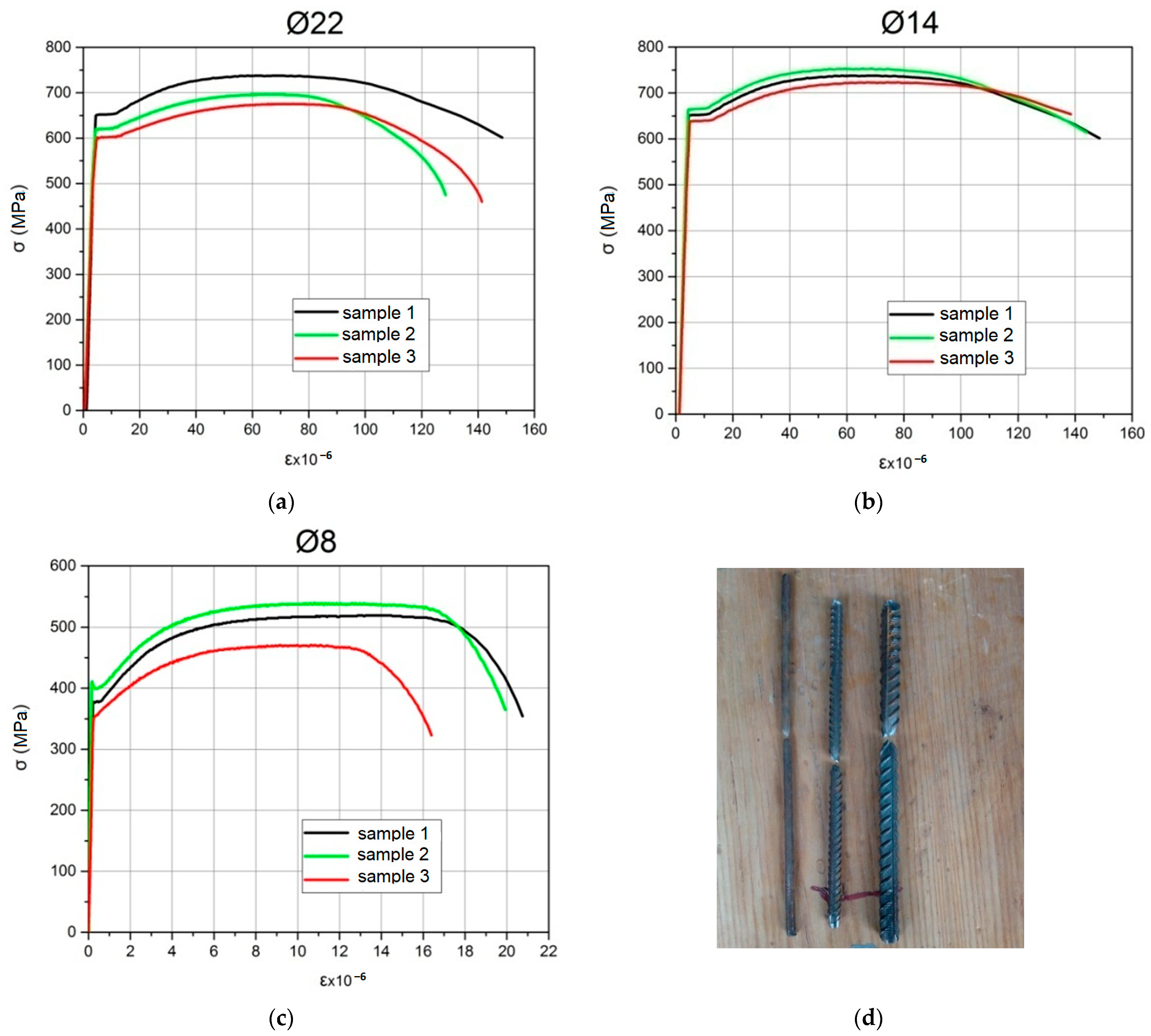
During the construction process, samples of reinforcement bars and concrete were collected to obtain the actual physical and mechanical characteristics of the materials. The reinforcement bar samples were taken directly during the production of the reinforcement frameworks, from the same batch of bars. In accordance with [18], the properties of the reinforcement steel were determined through tensile testing of control samples, each 400 mm long, with three test samples for each diameter. The tests were conducted using the E4S-20 tensile testing machine. Based on the results of the tests, deformation diagrams of the tested samples were constructed, as shown in Figure 2.
As a result, the rebar characteristics were obtained, and their values are listed in Table 1.
Based on the test results, it can be concluded that both compressed and tensile reinforcement belong to class A500C, while the smooth transverse reinforcement belongs to class A240C.
Based on the requirement in [19], the determination of the physical and mechanical properties of the concrete was carried out using standard cube, prism, and cylinder samples. The samples were formed from the same concrete batch as the experimental beams. A total of 12 cubes, 8 prisms, and 12 cylinders were produced. The concrete samples were tested at the age of 28 days—before the testing of the experimental beams (1st series) and after the completion of all the tests (2nd series). The tests were conducted on the PG-250 hydraulic press.
Determination of the concrete properties was carried out in accordance with the requirements of the code [19]. The modulus of elasticity and Poisson’s ratio were determined on the concrete prisms. For this, longitudinal and transverse gauges were placed on each surface, which measured the longitudinal and transverse strains, respectively. Measurements were carried out up to the load level, which was 50% of the expected destructive one, based on the results of testing the cubes. After that, strains at a value of 30% of the concrete strength were determined for the modulus of elasticity. To determine the Poisson’s ratio, the ratio of the transverse strains of the prism to its longitudinal ones was established.
The experimental physical and mechanical properties of the concrete were determined based on the testing of cubes, prisms, and cylinders, as shown in Table 2.
Based on the results of the concrete sample testing, it was determined that the concrete belongs to class C30 [20] (C32/40 according Ukrainian codes [21]).
The strengthening element was a composite FRCM (fiber-reinforced cementitious matrix) system, which consists of two components: the Ruredil X Mesh M750 mineral solution and the P.B.O. composite fabric Ruredil X Mesh Gold (Figure 3). The characteristics of the fabric were taken from the certificate provided by the manufacturer [22], as this is a highly technical material produced in Italy with quality control at all stages of production. The specifications are presented in Table 3.
The strength of the solution was established by experimental tests of 9 cubes with a side of 70 mm, formed before the tests. The samples were tested at the age of 10, 20, and 28 days on a PG-125 hydraulic press. The results of the tests showed that the mortar gained a compressive strength of 29 MPa at the age of 10 days, 36 MPa at the age of 20 days, and 40 MPa at the age of 28 days. The strength of the solution of the used consistency for 10 days corresponds to the strength of the solution declared by the manufacturer for 28 days. Since the reinforced concrete beams were tested 10 days after strengthening, the physical and mechanical characteristics given in Table 4 follow the data the manufacturer declared.
During each test, 3 similar cubes were formed to check the strength of the strengthening solution (Figure 4).
The test results of the strengthening solution cubes showed a strength variation of no more than 10% compared to the control tests, which confirms that the physical and mechanical properties of the mixture comply with the manufacturer’s specifications.

2.3. Methodology of Applying the Strengthening System

According to the experimental research program, the testing of 5 reinforced concrete beams was planned, with one serving as a control sample to establish the stress–strain state. The remaining beams were tested with strengthening applied at different levels of initial loading (Table 5).
The testing of the experimental samples was performed using a single-span beam setup on two supports, with a span of 1900 mm, loaded with two forces placed at equal distances from the supports, following the “pure bending” loading type. The load was applied to the beam in such a way that its plane coincided with the center of gravity of the beam’s cross-section.
The load level at which strengthening was performed was chosen from the following conditions: without the initial loading level–idealized conditions that were adopted to obtain the maximum possible effect of using the strengthening system; 0.3 from the bearing capacity–an approximate load level that corresponds to the own weight of the structure and the construction located above; 0.5 from the bearing capacity is the loading level at which the real work of the structure begins (construction is affected by self-weight and dead load); 0.7 from the bearing capacity is the level that corresponds to the impact on the beam of the entire design load (this level occurs taking into account all the reserves and reliability coefficients accepted in the calculation). Also, a level of 0.9 from the carrying capacity was planned, but at the level of 0.7, a low value of the increase in the carrying capacity was obtained (approximately 15%). The strengthening effect at the level of 0.9 could not be observed at all, or it would be very low.
This research was conducted for each inclined section separately [7]. Testing using this method allows for significantly reduced material costs, labor intensity, and number of measuring devices required. A similar testing method is presented in [23,24], although in that case, the shear span of the beam and the loading scheme were reduced, without the use of a steel collar, which altered the stress state of the beam’s longitudinal reinforcement.
A shear span a/d = 2 was chosen based on the testing of the 3 control samples [7]. In these control samples, the ratio was 1, 1.5 and 2. So, this was a study of supporting areas with a small shear ratio, in which the effect of the coefficient β must be included. In general, a ratio a/d = 2 was chosen because in this case the bearing capacity of the control samples was the lowest, and we can use the most fabrics for reinforcement.
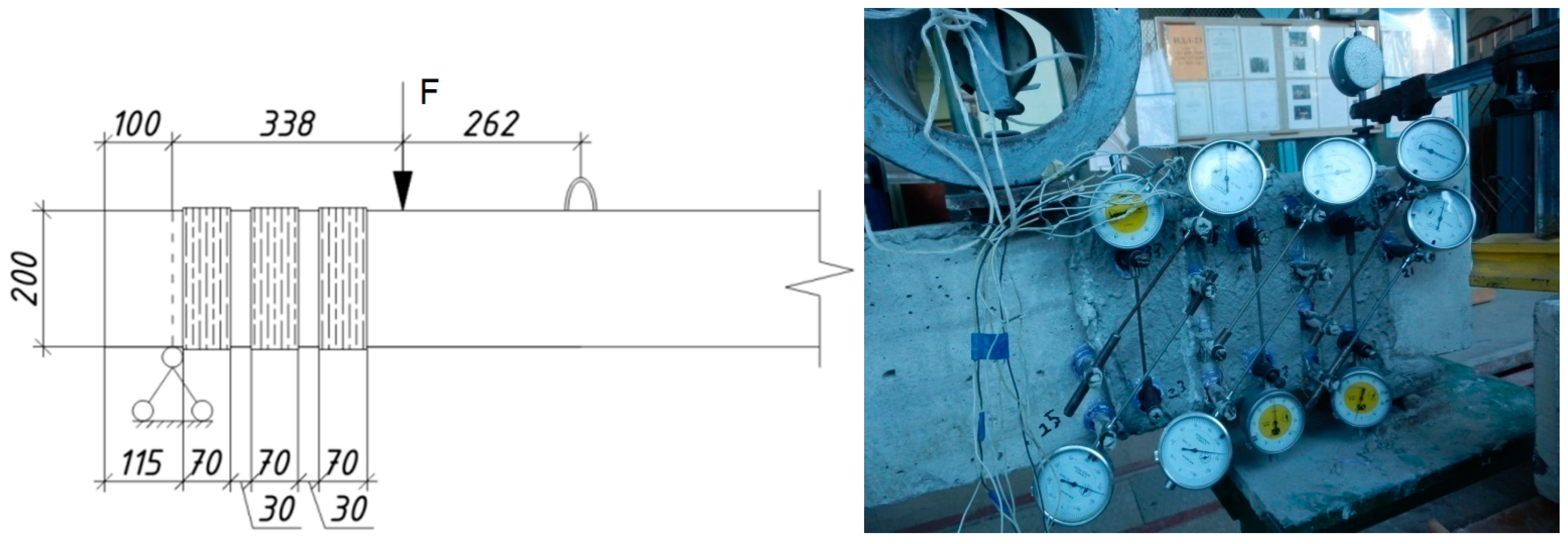
After testing the control samples, the levels of strengthening were determined according to the experimental program mentioned above. The strengthening was performed using a mesh made of P.B.O. fibers, specifically Ruredil X Mesh Gold, embedded in a stabilized inorganic matrix to enhance the concrete’s bending and shear strength. The strengthening was carried out using one layer of vertical fabric strips, 70 mm wide, spaced 100 mm apart (the distance measured between strips centers), which were adhered to the concrete and placed between the steel internal reinforcement (Figure 5). The ends of the reinforcing fabric strips were overlapped on the upper surface of the beam. The overlay was 10 cm. When performing the reinforcement, the corners of the beam were rounded (according to the manufacturer’s recommendations [22]). This type of strengthening allowed for the fixation of concrete deformations in the support sections.
The strengthening was applied with one layer of external reinforcement. After completing the installation of the strengthening system, a curing period of 10 days was observed to allow the mineral solution to gain strength. Following this, testing was resumed similarly to the unstrengthened beams. During the curing period, the required load level on the beam was monitored.
The Ruredil X Mesh Gold strengthening system was applied quickly, with the reinforcement of a single inclined section taking 40 min, including all the related tasks, and it did not require additional construction materials.

3. Results of the Experimental Testing

3.1. Bending Capacity of Testing Beams

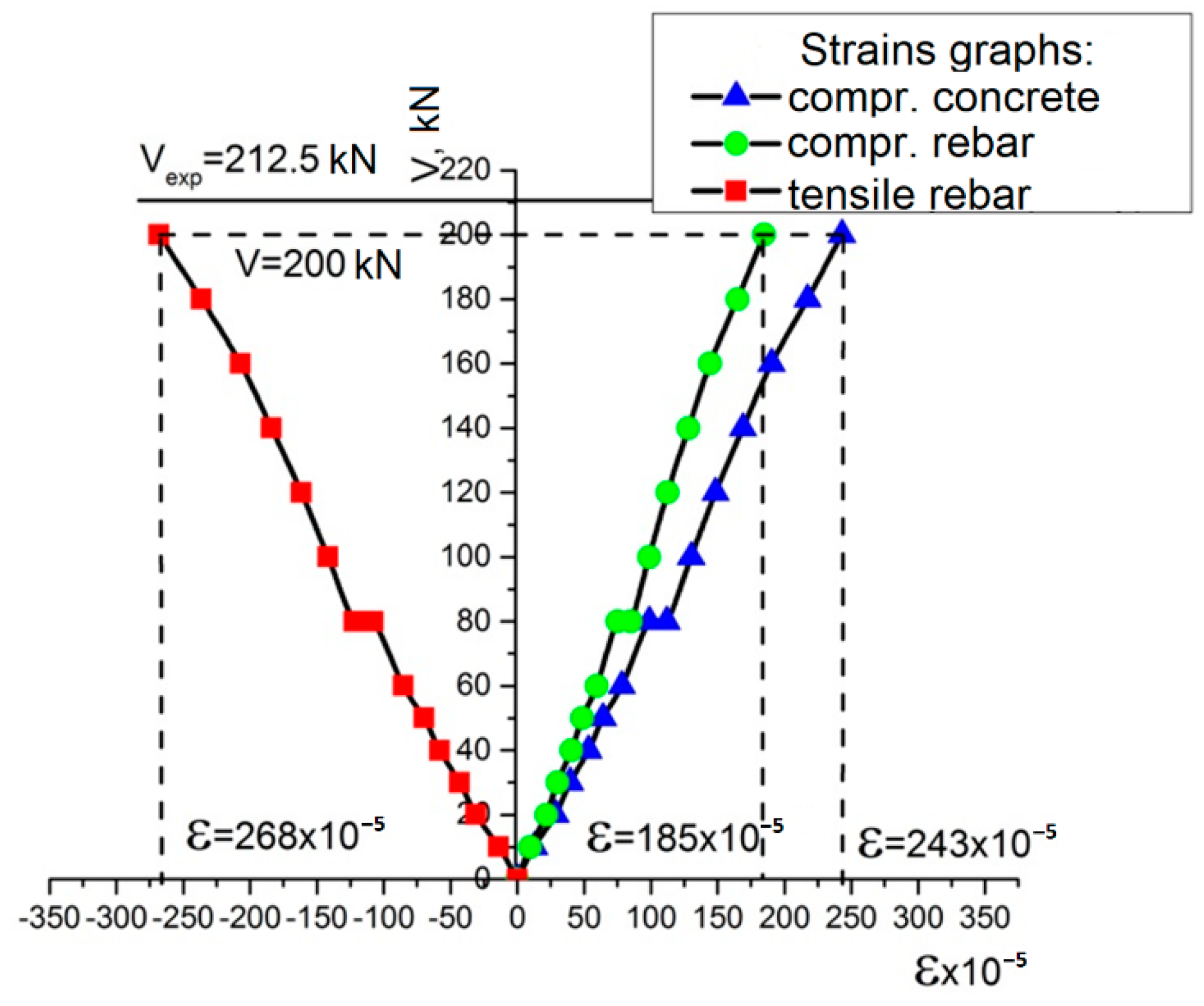
The experimental samples were designed in such a way that, even after strengthening, failure occurred on the shear. For this purpose, the tensile reinforcement in the reinforced concrete beams from both series was designed with a significant reserve, which is typical for such studies. During the tests, the strains of the compressed concrete zone, as well as the compressed and tensile reinforcement, were recorded. Figure 6 shows the average strains for beam BSC 2.3.1-0.5, which collapsed at the value of the loading force Ve = 212.5 kN, which corresponds to the maximum bending moment ME = 71.3 kNm, among all the test samples.
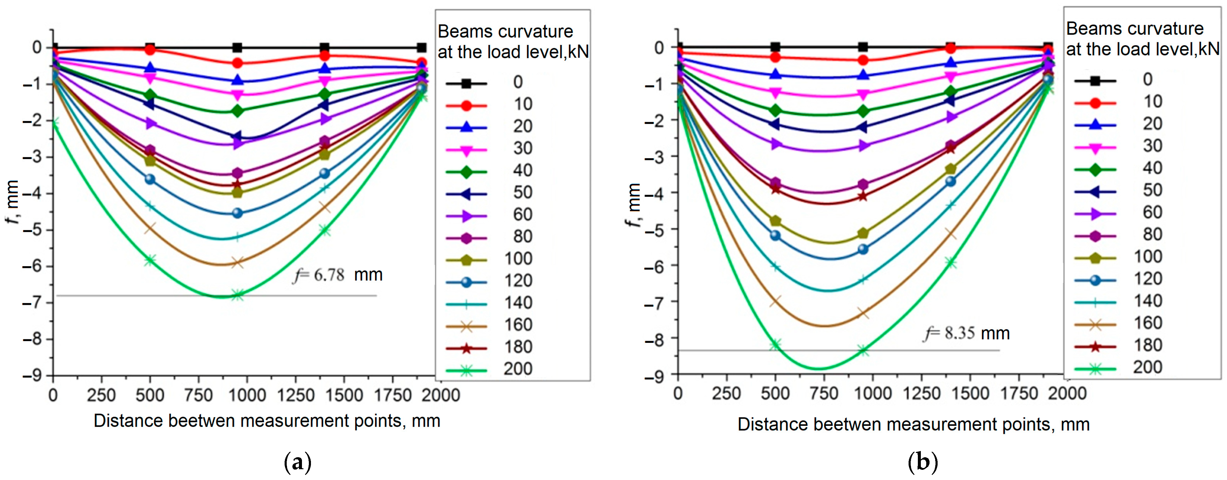
The assessment of the impact of the steel collar on the curvature of the beam was conducted based on the experimentally obtained deflections, which were recorded at characteristic points. Figure 7 shows the deflected shape of the beam, which was tested with a shear span of a/d = 2.
According to the codes [21], the allowable deflection for beams is fu = l0/150, which corresponds to fu = 12.7 mm. In the experimental samples, the maximum deflection was 8.35 mm, which is significantly lower (by 35%) than the allowable limit. Such a comparison was used to demonstrate that the bearing capacity for the bending moment was ensured even according to the requirements of the II group of the limit states (SLSs). It is worth noting that the experimental beams exhibited some asymmetry in the deflected shape, caused by the change in stiffness due to the steel collar installed at one end. The maximum deflection values were recorded in the middle of the beam span during the testing of both sections of the experimental specimen.
Based on the analysis of the bending moment bearing capacity, at the maximum applied load, their strength was ensured.

3.2. Experimental Research of Control Samples on the Shear

Reaching the ultimate strains in the transverse reinforcement cannot be considered a criterion for the exhaustion of the bearing capacity, as shear failure of the reinforcement bars occurs, leading to the onset of the yield point before the ultimate strains of the reinforcement are reached.
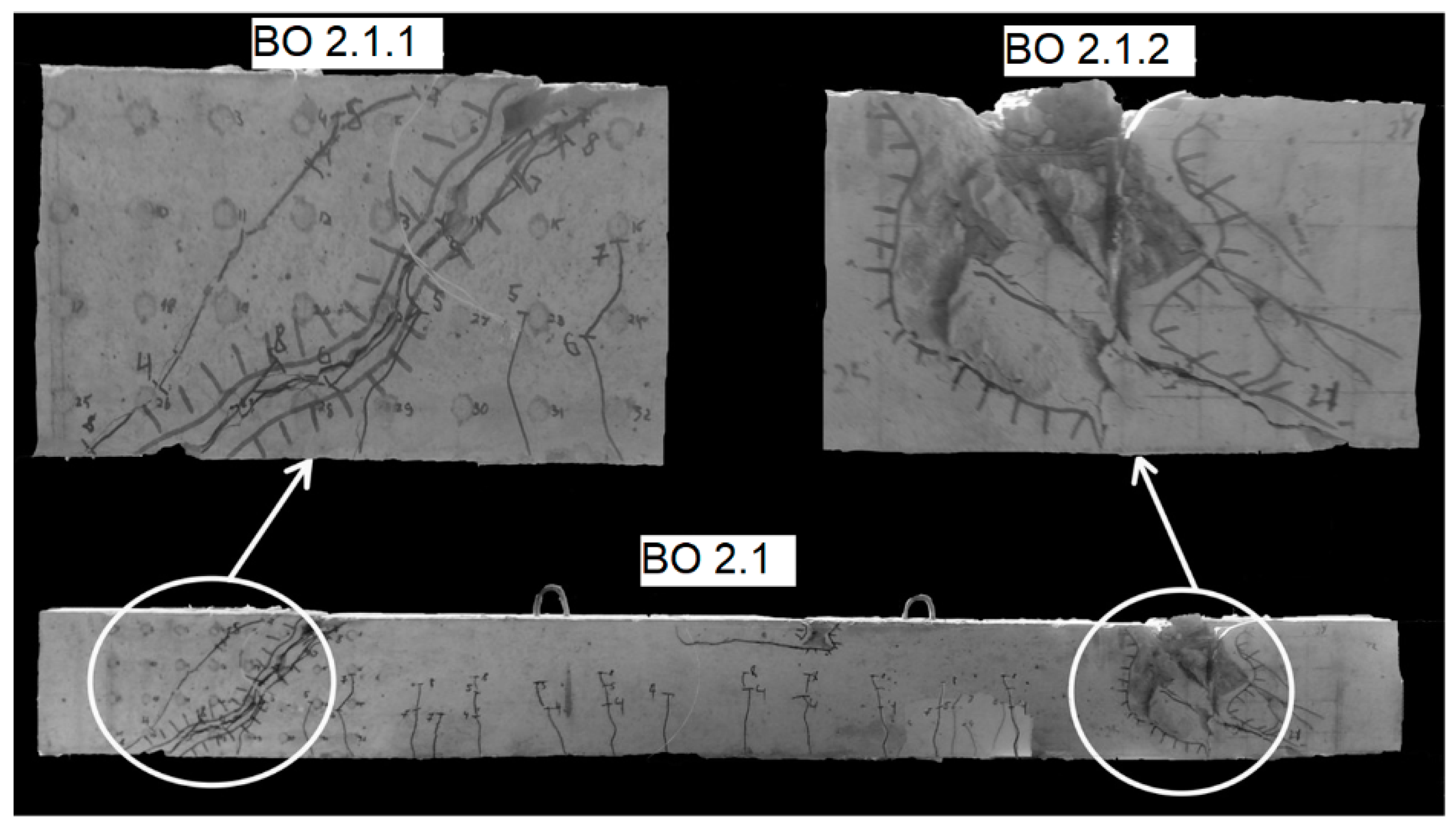
The tested control specimen is shown in Figure 8.
The shear bearing capacity was as follows: for BO 2.1 − VE=148.5 kN.
The stress distribution in the reinforced support sections is characterized by higher tensile strains in the elements and the concentration of maximum deformations in the zone where the maximum tensile stresses occur (Figure 9).
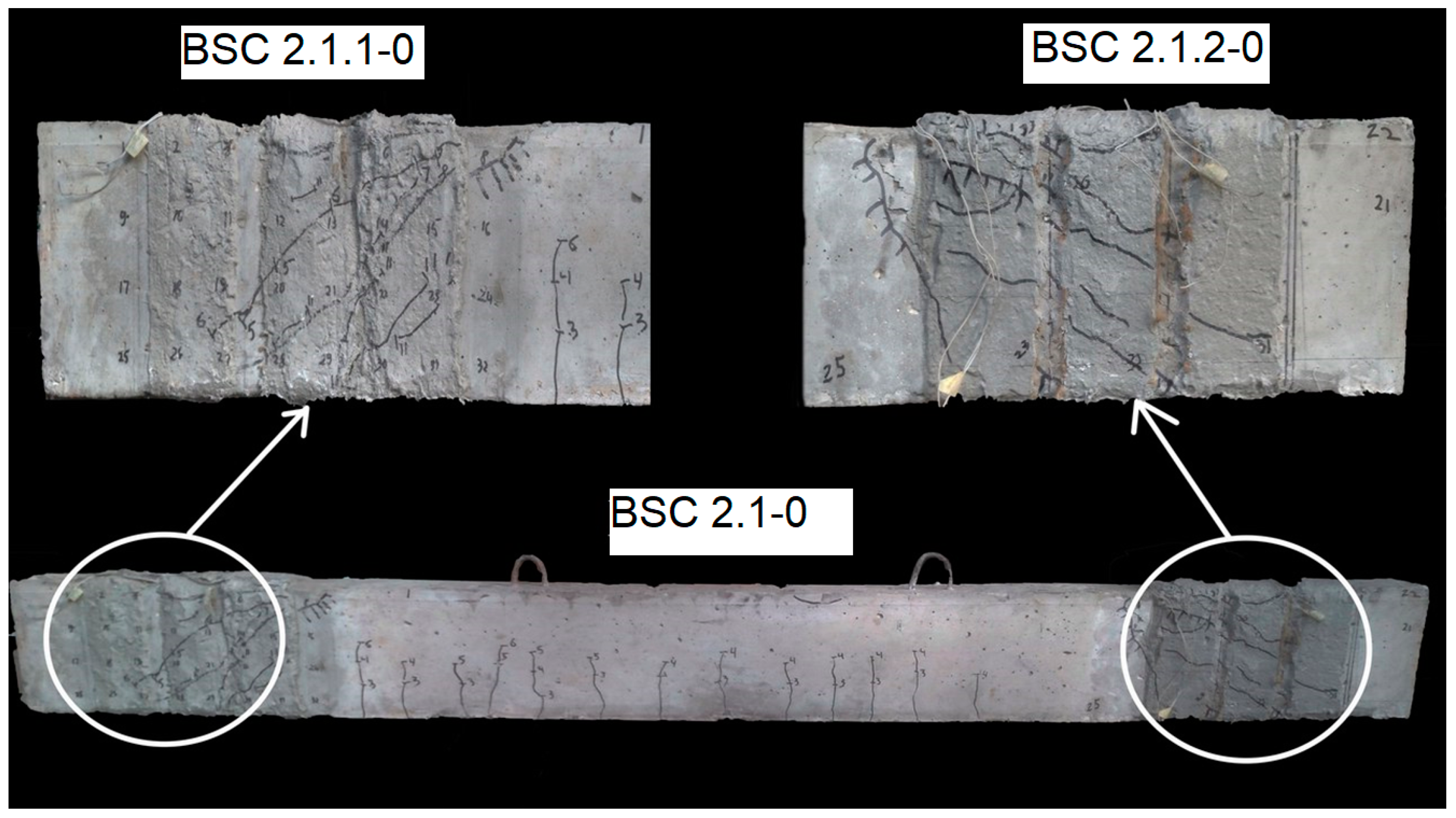
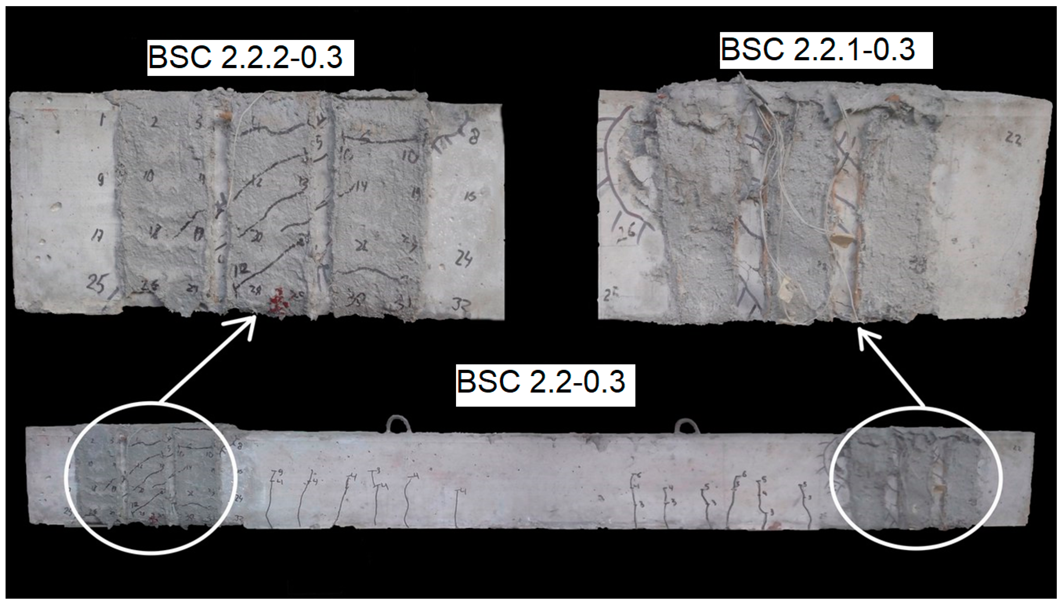
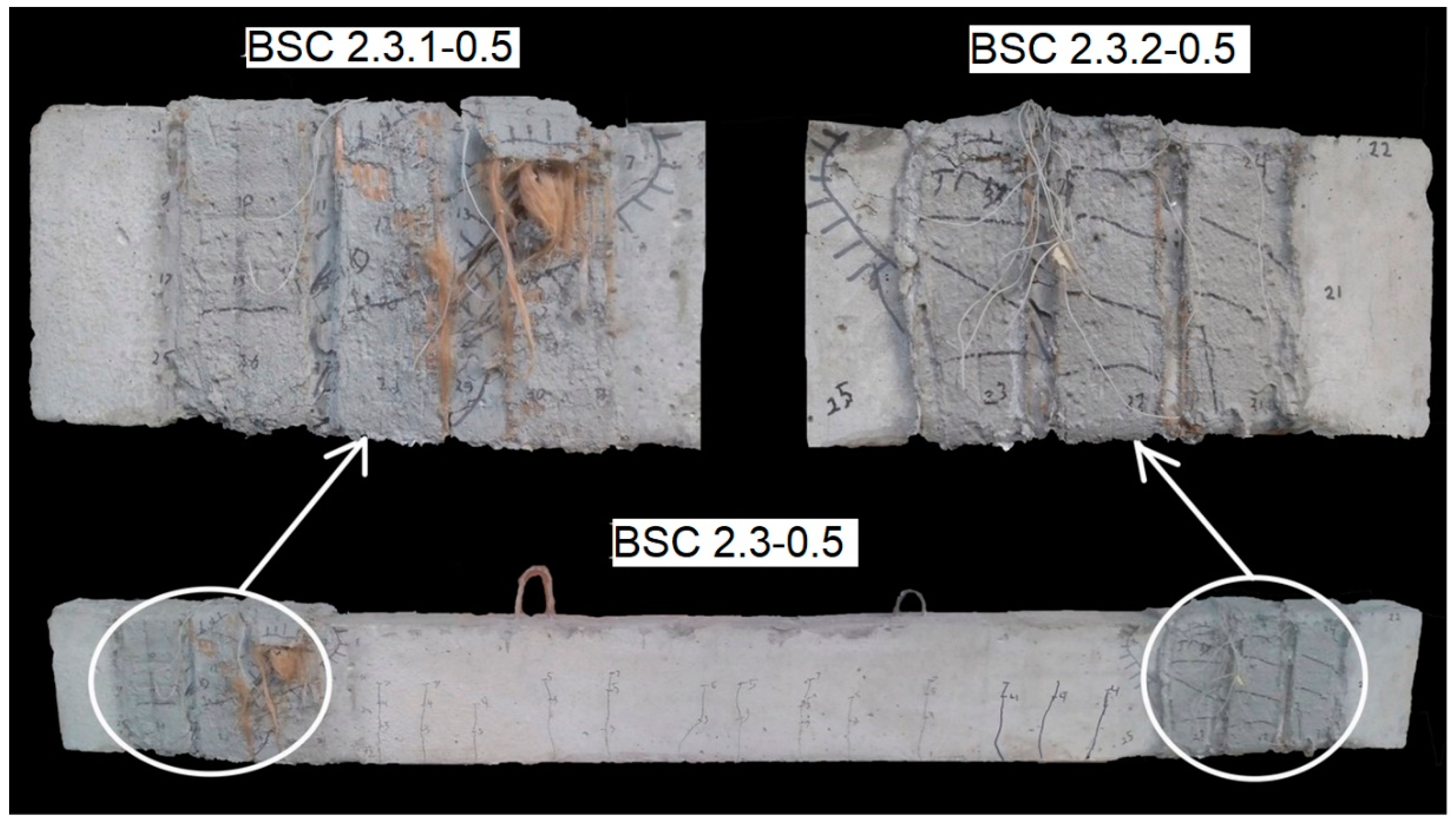
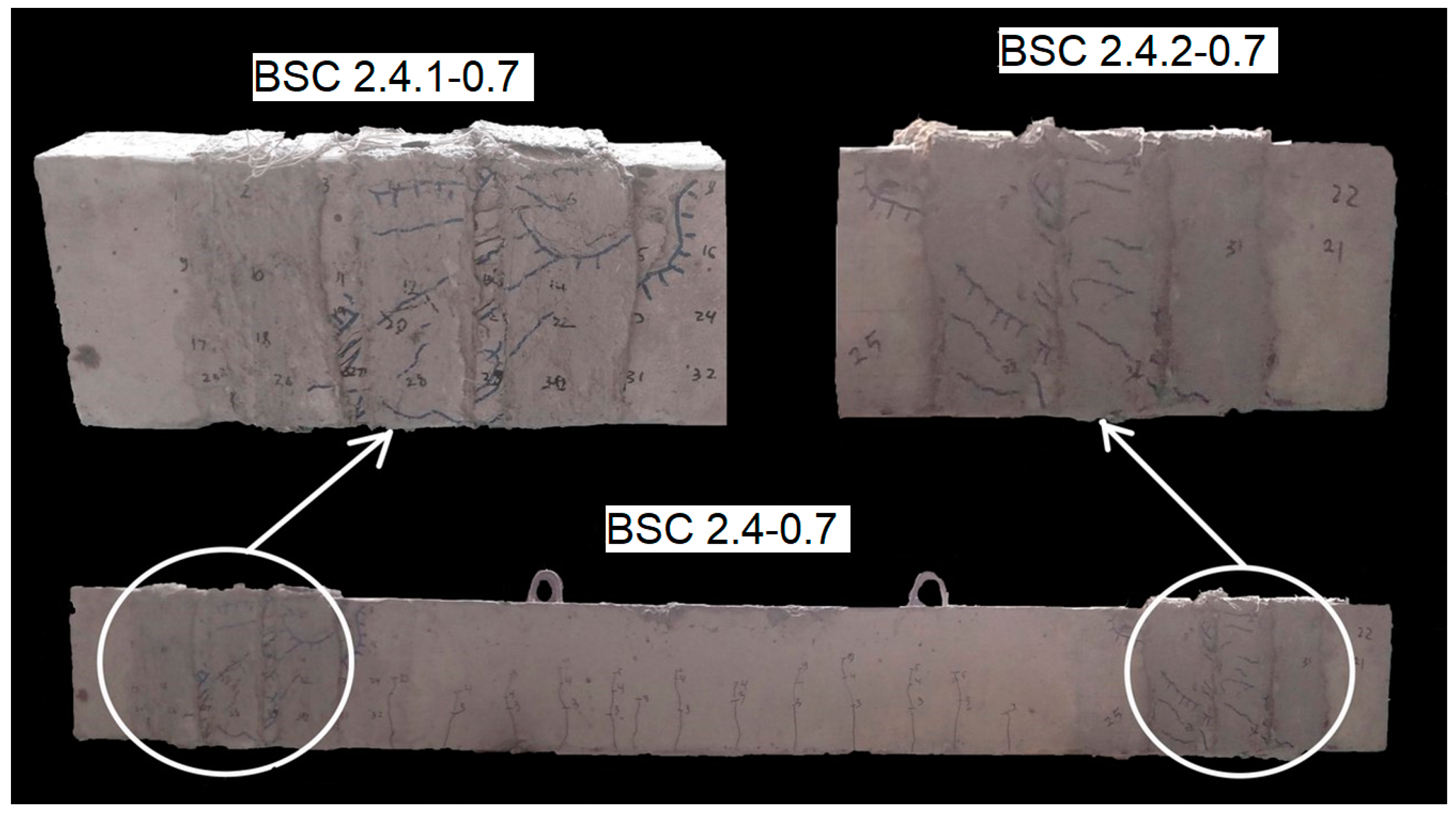
The failure of the experimental samples occurred similarly to that of the strengthened beams without transverse reinforcement (Figure 10, Figure 11, Figure 12 and Figure 13):
  • The formation of an inclined crack with a critical width (acrc = 0.4 mm) on the surface of the concrete.
  • The propagation of the inclined crack into the compressed concrete zone and the appearance of a crack network with an opening width of acrc = 0.05…0.2 mm on the surface of the strengthening system.
  • The failure of the concrete in the inclined section in the zone of the principal tensile stresses and the delamination of the strengthening system in this area.
  • The plastic deformation of the transverse reinforcement and failure of the concrete in the compressed zone, with significant deformations in the strengthening fabric, which could be visually observed due to the disruption of the protective layer.
In some cases, significant elongation of the strengthening fabric was observed (Figure 12) during the physical failure of the samples; however, the fabric remained intact, without tearing.
The visual signs of the exhaustion of the bearing capacity include minor spalling of the compressed concrete zone on the side of load application, where no strengthening was applied, and a residual deflection of the beam, which amounted to f = 1...3  mm.
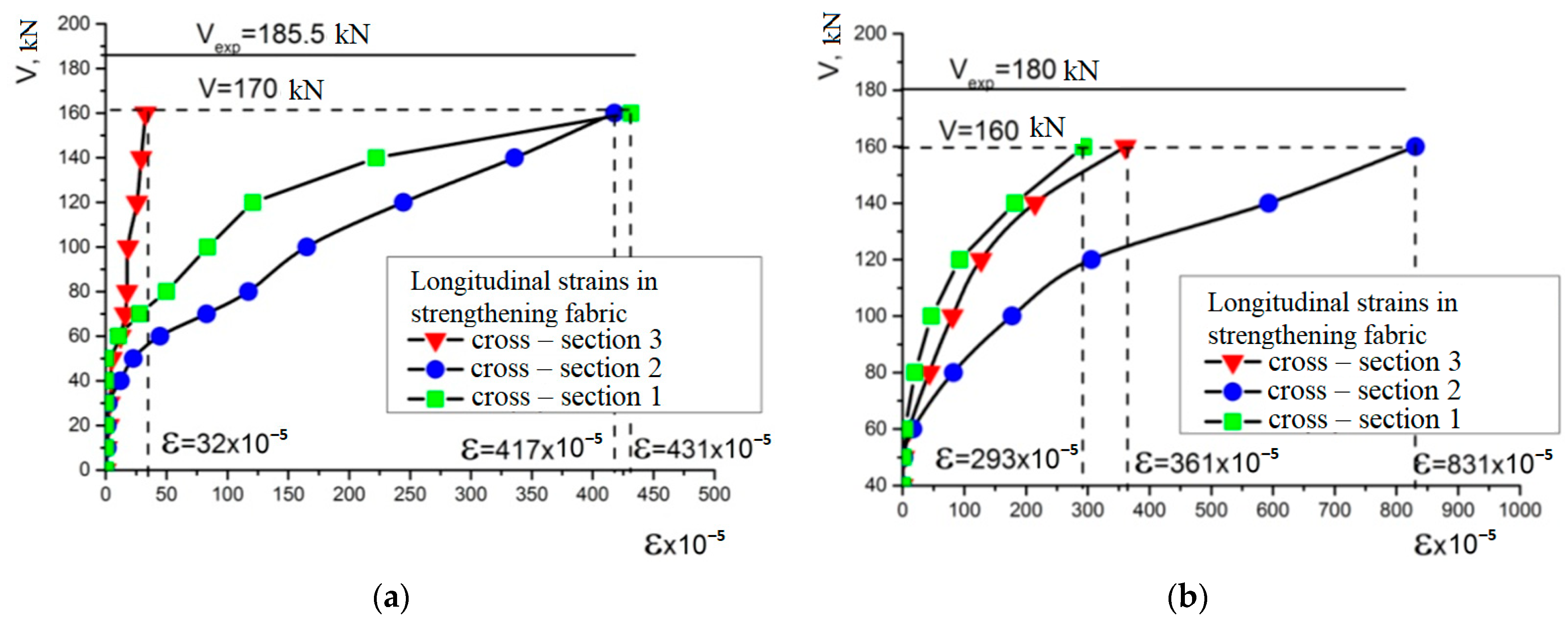
The strain of the transverse reinforcement for beams BSC 2.1-0 and BSC 2.2-0.3 shows a similar distribution pattern (Figure 14).
The largest deformations were recorded in Section 2 and Section 3 (Figure 14d) and reached maximum tensile strains of ε = 385 × 10 5 . This is related to the achievement of the principal tensile forces at their maximum values, while compressive forces may occur in Section 3.
The higher strains in the P.B.O. fabrics are characterized by experimental beam BSC 2.2-0.3 (Figure 15) ε = 831 × 10 5 , whichs 39% of the maximum elongation of the tape.
This effect is a consequence of the strengthening applied just before the formation of the inclined crack—by this point, the concrete’s tensile strength has essentially been exhausted, and the primary increase in deformations occurs in the zone of crack development. As the load level increases, the effectiveness of the tape diminishes due to the development of plastic deformations in the inclined section, leading to the opening and propagation of the inclined crack. When strengthening is applied at a level of 0.5∙Vexp, the tape is still maximally effective, absorbing nearly the same deformations as it would without initial loading. However, when strengthening is applied at a level of 0.7 of the bearing capacity of the control specimen, only one strip effectively engages. The strengthening element absorbs most of the deformations during the pre-failure state of the inclined section.
The increase in the bearing capacity for the strengthened reinforced concrete beams is presented in Table 6.
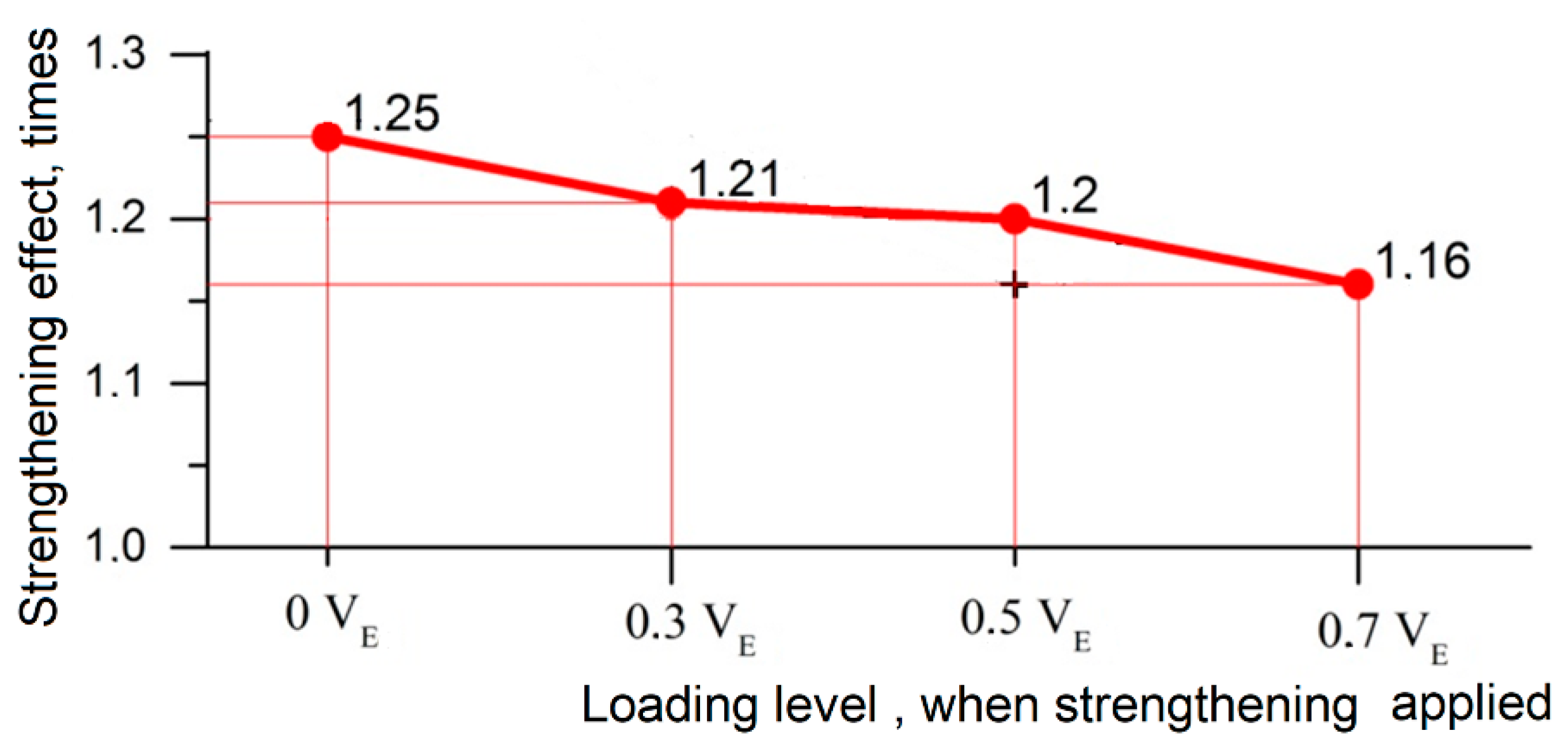
For the samples strengthened with vertical strips, the maximum bearing capacity was demonstrated by beam BSC 2.1-0, reaching 185.5 kN, which represents a 1.25-fold increase in capacity. As the level of pre-loading increases, the bearing capacity of the inclined sections decreases to 171 kN, indicating a 1.16-fold increase in capacity.
If we analyze the change in the strengthening effect—the value of the increase in the bearing capacity of the beam—then it is the largest with strengthening without an initial loading, 37 kN, and subsequently only decreases (Table 7).
It is worth noting that the strengthening effect decreased by almost 40% when we performed strengthening at a loading level of 0.7 from the expected destruction of the control beams.

4. Discussion

This study analyzed the impact of the load level at which the strengthening of reinforced concrete structures is performed on the resulting increase in the shear strength. Such research is crucial because, in real-world strengthening projects, it is often impossible to completely unload the structure (although this article provides comparative results for fully unloaded structures). The structure remains subject to the following.
The self-weight of the structure and the weight of overlying structures, which are difficult or often impossible to dismantle (approximately 30% of the bearing capacity).
Additional dead and live loads, which are also frequently challenging to remove. In such cases, the load level in the beam is approximately 0.5–0.7 of its full load-bearing capacity.
The research presented in this article was conducted within these load ranges. For the experimental samples, the maximum strengthening effect recorded was a 25% increase, which decreased to 16% at a load level of 0.7 of the expected failure loads. The reduction in the strengthening effect is close to linear, as shown in Figure 16.
Analyzing the graph in Figure 16, it can be determined that in the absence of initial loading, a strengthening effect of 25% was achieved, while at 70% of the expected failure load of the control samples, the effect decreased to only 16%. In terms of the shear strength, this corresponds to a reduction from 37 kN to 22.5 kN, which is approximately a 39% decrease. Based on this, it can be concluded that the reduction in the strengthening effect is essentially a linear function, which fits well with the experimental results.
Thus, when performing shear strengthening of reinforced concrete beams, the strengthening effect should be reduced by 5% for every 10% of the applied load relative to the failure load. For example, at 10% of the failure load, the effect decreases by 5%, at 20%, it decreases by 10%, and so on. At this point, this is an empirical hypothesis derived through experimental means, and it requires further statistical and theoretical analysis.

5. Conclusions

Based on the above results, the following conclusions can be drawn from this study:
  • It is worth noting the change in the nature of the failure of reinforced concrete beams under shear, which became smoother and more predictable, without the detachment of damaged particles. This indicates the effectiveness of using composite systems for strengthening reinforced concrete structures and improving their operational safety.
  • The use of the strengthening tape in this study resulted in a 40% increase in the shear capacity of reinforced concrete beams, which is a satisfactory outcome.
  • When strengthening reinforced concrete beams with external reinforcement equivalent to the internal reinforcement section and reducing the spacing of the transverse reinforcement by half, the bearing capacity of the inclined section increases by 25%.
  • The load level at which the strengthening is performed significantly affects the increase in the bearing capacity, reducing it to near 40% when the load level on the structure is 70% of its maximum capacity.
  • For every 10% increase in the load level at which the strengthening is carried out, the maximum strengthening effect achievable by this system should be reduced by 5%. This dependency should be considered for future work at other load levels.

Author Contributions

Conceptualization, P.V., Z.B. and V.B.; methodology, P.V.; software, I.G.; validation, J.B., V.B. and P.V.; formal analysis, I.G. and Z.B.; investigation, P.V. and Z.B.; resources, V.B.; data curation, J.B. and P.V.; writing—original draft preparation, P.V. and I.G.; writing—review and editing, I.G.; visualization, J.B. and I.G.; supervision, V.B.; project administration, P.V. and Z.B.; funding acquisition, V.B. All authors have read and agreed to the published version of the manuscript.

Funding

This work was supported by the Scientific Grant Agency VEGA under contract no. VEGA 1/0358/23. This work was also supported by the Slovak Research and Development Agency under contract no. APVV-23-0193.

Data Availability Statement

The original contributions presented in the study are included in the article, further inquiries can be directed to the corresponding author.

Acknowledgments

The publication of this article was made possible with the support of the SAIA scholarship.

Conflicts of Interest

The authors declare no conflicts of interest.

References

  1. Khmil, R.; Blikharskyy, Z.; Vegera, P.; Kopiika, N. Bearing capacity of reinforced concrete beams with and without damages of rebar. Prod. Eng. Arch. 2023, 29, 298–303. [Google Scholar] [CrossRef]
  2. Kopiika, N.; Vegera, P.; Vashkevych, R.; Blikharskyy, Z. Stress-strain state of damaged reinforced concrete bended elements at operational load level. Prod. Eng. Arch. 2021, 27, 242–247. [Google Scholar] [CrossRef]
  3. Vegera, P.; Vashkevych, R.; Blikharskyy, Y.; Khmil, R. Development methodology of determinating residual carrying capacity of reinforced concrete beams with damages tensile reinforcement which occurred during loading. East.-Eur. J. Enterp. Technol. 2021, 4, 6–17. [Google Scholar] [CrossRef]
  4. Klymenko, Y.; Polianskyi, K.; Grynyova, I.; Borzovič, V. Influence of Damage in the Compressed Zone of Concrete on the Bearing Capacity Along Inclined Sections and Crack Formation Characteristics. Lect. Notes Civ. Eng. 2024, 604, 225–234. [Google Scholar] [CrossRef]
  5. Šarvaicová, S.; Borzovič, V.; Halvonik, J. Experimental investigation of punching shear behavior of flat slabs supported by rectangular columns and loaded with various load patterns. Struct. Concr. 2024, 25, 1404–1417. [Google Scholar] [CrossRef]
  6. Selejdak, J.; Bobalo, T.; Blikharskyy, Y.; Dankevych, I. Mathematical modelling of stress-strain state of steel-concrete beams with combined reinforcement. Prod. Eng. Arch. 2023, 29, 108–115. [Google Scholar] [CrossRef]
  7. Vegera, P.; Borzovic, V.; Blikharskyi, Z.; Khmil, R. Experimental data of RC beams shear strength with different shear span and strengthening by FRCM system. Web Conf. 2024, 550, 01007. [Google Scholar] [CrossRef]
  8. Blikharskyy, Y.; Khmil, R.; Selejdak, J.; Katunský, D.; Tytarenko, R.; Blikharskyy, Z. Crack Resistance of RC Columns Strengthened By CFRP Under 30% of Uls Loading. Syst. Saf. Hum.-Tech. Facil.-Environ. 2023, 5, 36–45. [Google Scholar] [CrossRef]
  9. Feng, R.; Tang, J.P.; Wang, F.; Wang, S.; Zeng, J.J.; Zhu, J.H. Experiments on shear behavior of reinforced concrete continuous beams strengthened by C-FRCM. Struct. Concr. 2024, 25, 1052–1075. [Google Scholar] [CrossRef]
  10. Gemi, L.; Alsdudi, M.; Aksoylu, C.; Yazman, Ş.; Özkılıç, Y.O.; Arslan, M.H. Optimum amount of CFRP for strengthening shear deficient reinforced concrete beams. Steel Compos. Struct. 2022, 43, 735–757. [Google Scholar] [CrossRef]
  11. Zapris, A.G.; Kytinou, V.K.; Gribniak, V.; Chalioris, C.E. Novel approach for strengthening T-beams deficient in shear with near-surface mounted CFRP ropes in form of closed stirrups. Dev. Built Environ. 2024, 18, 100394. [Google Scholar] [CrossRef]
  12. Taie, B.; Mandor, A.; El Refai, A. Experimental and numerical investigation of two–span RC beams strengthened with fiber–reinforced cementitious matrix (FRCM). Eng. Struct. 2024, 300, 117246. [Google Scholar] [CrossRef]
  13. Mendizabal, V.; Martínez, B.; Bernat-Maso, E.; Gil, L. RC beams strengthened with hemp-FRCM and cotton-FRCM under cyclic bending loads. Eng. Struct. 2024, 318, 118718. [Google Scholar] [CrossRef]
  14. Teixeira, F.P.; de Souza, F.R.; Garcia SL, G.; de Andrade Silva, F. Strengthening and repair of RC beams using natural sisal Fabric-Reinforced Cementitious Matrix composite. Constr. Build. Mater. 2024, 447, 138047. [Google Scholar] [CrossRef]
  15. Jung, C.; Seo, Y.; Hong, J.; Heo, J.; Cho, H.C.; Ju, H. Experimental Study on Shear Strengthening of Reinforced Concrete Beams by Fabric-Reinforced Cementitious Matrix. Materials 2024, 17, 4336. [Google Scholar] [CrossRef] [PubMed]
  16. Calabrese, A.S.; Colombi, P.; D’Antino, T. Fatigue and post-fatigue behavior of FRCM-concrete specimens under direct shear and bending conditions. Compos. Struct. 2024, 341, 118129. [Google Scholar] [CrossRef]
  17. Focacci, F.; D’Antino, T.; Carloni, C. Simplified Procedure to Determine the Cohesive Material Law of Fiber-Reinforced Cementitious Matrix (FRCM)–Substrate Joints. Materials 2024, 17, 1627. [Google Scholar] [CrossRef] [PubMed]
  18. DSTU 3760:2006; Rolled Rebar for Reinforced Concrete Structures. General Technical Conditions: National Code of Ukraine. Institute of Ferrous Metallurgy of the National Academy of Sciences of Ukraine: Dnipro, Ukraine, 2006; 28p. Available online: https://td-slavsant.com/wp-content/gst/arm/dstu-3760-06.pdf (accessed on 16 November 2024).
  19. DSTU B V.2.7-217:2009; Methods of Determining Prism Strength, Modulus of Elasticity and Poisson’s Ratio: National code of Ukraine. Ministry of Construction Region of Ukraine: Kyiv, Ukraine, 2010; 20p. Available online: https://dbn.co.ua/load/normativy/dstu/5-1-0-1089 (accessed on 16 November 2024). (In Ukrainian)
  20. EN 1992-1-1; Eurocode 2: Design of Concrete Structures—Part 1-1. General Rules for Buildings: Brussels, Belgium, 2004. Available online: https://www.phd.eng.br/wp-content/uploads/2015/12/en.1992.1.1.2004.pdf (accessed on 16 November 2024).
  21. DBN V.2.6-98:2009; Concrete and Reinforced Concrete Structures: National code of Ukraine. Ministry of Construction Region of Ukraine: Kyiv, Ukraine, 2011; 68p. Available online: https://e-construction.gov.ua/laws_detail/3200410998024438840?doc_type=2 (accessed on 16 November 2024). (In Ukrainian)
  22. Ruredil Spa Technical Department. Instruction for the Planning of Static Consolidation Interventions Through the Use of Fibre Reinforced Cementitious Matrix; FRCM: Milan, Italy, 2008; 201p. [Google Scholar]
  23. Alzate, A.; Arteaga, A.; de Diego, A.; Cisneros, D.; Perera, R. Shear Strengthening of Reinforced Concrete Members with CFRP Sheets. Mater. Construcción 2013, 63, 251–265. [Google Scholar]
  24. Halvonik, J.; Borzovič; V; Lániova, D. Comparison of shear behaviour of concrete beams reinforced with GFRP bars and steel bars. Structures 2022, 43, 657–668. [Google Scholar] [CrossRef]
Figure 1. Reinforcement of the testing specimens.
Constrmater 04 00039 g001
Figure 2. Testing of the reinforcement samples: (a) stress–strain diagram for reinforcement ∅22; (b) stress–strain diagram for reinforcement ∅14; (c) stress–strain diagram for reinforcement ∅8; and (d) general view of the tested reinforcement samples.
Constrmater 04 00039 g002
Figure 3. Components of the strengthening system: (a) P.B.O. fabric Ruredil X Mesh Gold; and (b) mineral cementitious solution Ruredil X Mesh M750.
Constrmater 04 00039 g003
Figure 4. Testing of the Ruredil X Mesh M750 mortar cubes: (a) compression test process; and (b) tested samples from one series.
Constrmater 04 00039 g004
Figure 5. Strengthening system layout on an experimental specimen.
Constrmater 04 00039 g005
Figure 6. A graph of the deformations of the compressed zone of concrete, stretched and compressed reinforcement in beam BSC 2.3-0.5.
Constrmater 04 00039 g006
Figure 7. The deflection of the BSC 2.3-0.5 beam: (a) of the BSC 2.3.1-0.5; and (b) of BSC2.3.2-0.5.
Constrmater 04 00039 g007
Figure 8. Tested specimen BO 2.1.
Constrmater 04 00039 g008
Figure 9. The strains of the transverse reinforcement of beam BO 2.1:(a) graph of the strains in the transverse reinforcement (b) placement of the measuring cross-sections.
Constrmater 04 00039 g009
Figure 10. Tested specimen BSC 2.1-0.
Constrmater 04 00039 g010
Figure 11. Tested specimen BSC 2.2-0.3.
Constrmater 04 00039 g011
Figure 12. Tested specimen BSC 2.3-0.5.
Constrmater 04 00039 g012
Figure 13. Tested specimen BSC 2.4-0.7.
Constrmater 04 00039 g013
Figure 14. The strains of the transverse reinforcement of the beam: (a) BSC 2.1-0; (b) BSC 2.2-0.3; (c) BSC 2.3-0.5; and (d) BSC 2.4-0.7.
Constrmater 04 00039 g014
Figure 15. The strains of the beam reinforcement element: (a) BSC 2.1-0; (b) BSC 2.2-0.3; (c) BSC 2.3-0.5; and (d) BSC 2.4-0.7.
Constrmater 04 00039 g015aConstrmater 04 00039 g015b
Figure 16. A graph of the reduction of the strengthening effect depending from the level of the active load.
Constrmater 04 00039 g016
Table 1. Physical and mechanical properties of the rebar.
RebarNumber of Test SamplesGeometric Dimensions (mm):fy
MPa
fu,
MPa
fyw,
MPa
εsεuEs,
GPa
Class
Smooth3Ø8, l = 400 mm376 301.4 A240C
Ribbed 3Ø14, l = 400 mm636.9722.8 0.003020.0482.11A500C
Ribbed3Ø22, l = 400 mm610.7701.5 0.002910.0702.10A500C
Table 2. Physical and mechanical properties of the concrete samples.
SampleNumber of Test SamplesGeometric Dimensions (mm):fc,cube
MPa
fc,
MPa
fct
MPa
fc,prism
MPa
Ec,
GPa
υClass
1st Series:
Cubes6150 × 150 × 15041.09-----C32/40
Prisms4150 × 150 × 600---30.4631.350.12
Cylinders
(for compression)
4100 × 200-30.49----
Cylinders
(for splitting)
4100 × 200--5.06---
2nd Series:
Cubes6150 × 150 × 15045.91-----C32/40
Prisms450 × 150 × 600---32.6633.390.12
Cylinders
(for compression)
4100 × 200-33.15----
Cylinders
(for splitting)
4100 × 200--6.13---
Table 3. Physical and mechanical properties of the Ruredil X Mesh Gold composite fabric.
ParameterValue
Weight of the mesh, g/cm21.56
Tensile strength, MPa 5800
Modulus of elasticity, GPa270
Ultimate strain, %2.15
Equivalent thickness of dry material in the longitudinal direction, mm0.0445
Equivalent thickness of dry material in the transverse direction, mm0.0115
Ultimate tensile strength in the longitudinal direction per unit width, kN/m264
Ultimate tensile strength in the transverse direction per unit width, kN/m66.5
Table 4. Physical and mechanical properties of the Ruredil X Mesh M750 cementitious solution.
ParameterValue
Water consumption per 100 kg of solution, L24–26
Consumption (dry product), kg/m2/mm1.210–1.230
Compressive strength at the age of 28 days, MPa29
Bending strength at the age of 28 days, MPa3.5
Modulus of elasticity, GPa6
Table 5. Program of the experimental research.
Name of the Testing BeamsName of the Testing Cross Section of the BeamType of the Researching
BO 2.1BO 2.1.1Non-strengthened with a/d = 2
(control sample)
BO 2.1.2
BSC 2.1-0BSC 2.1.1-0Strengthened without initial loading by three stirrups of composite materials
BSC 2.1.2-0
BSC 2.2-0.3BSC 2.2.1-0.3Strengthened at 30% load from bearing capacity of the control samples by three stirrups of composite materials
BSC 2.2.2-0.3
BSC 2.3-0.5BSC 2.3.1-0.5Strengthened at 50% load from bearing capacity of the control samples by three stirrups of composite materials
BSC 2.3.2-0.5
BSC 2.4-0.7BSC 2.4.1-0.7Strengthened at 70% load from bearing capacity of the control samples by three stirrups of composite materials
BSC 2.4.2-0.7
Table 6. Bearing capacity of reinforced concrete beams on the shear.
Name of the Testing BeamsName of the Testing Cross-Section of the BeamCross-Section bxh mmBeam Span, l0 mm Shear Span of the Section a/d The   Shear   Capacity   of   the   RC   Beam ,   V E e x p , kNThe Average Value of the Bearing Capacity,
V E e x p , kN
Increase   of   Bearing   Capacity ,   V E V E B O 2.1
BO 2.1BO 2.1.1201 × 10119002150148.5-
BO 2.1.2147
BSC 2.1-0BSC 2.1.1-0199 × 100187185.51.25
BSC 2.1.2-0184
BSC 2.2-0.3BSC 2.2.1-0.3200 × 1001811801.21
BSC 2.2.2-0.3179
BSC 2.3-0.5BSC 2.3.1-0.5201 × 98176.5178.251.20
BSC 2.3.2-0.5180
BSC 2.4-0.7BSC 2.4.1-0.7201 × 1011691711.16
BSC 2.4.2-0.7173
Table 7. Strengthening effectiveness of an FRCM system on the shear.
Name of the Testing BeamsName of the Testing Cross-Section of the Beam The   Shear   Capacity   of   the   RC   Beam ,   V E e x p , kNThe Average Value of the Bearing Capacity,
V E e x p , kN
Increasing Strengthening Value, kN V E , add exp = V E V E B O 2.1 Decreasing   of   Strengthening   Efficiently ,   V E , a d d V E , a d d B S C 2.1
BO 2.1BO 2.1.1150148.5--
BO 2.1.2147
BSC 2.1-0BSC 2.1.1-0187185.5371
BSC 2.1.2-0184
BSC 2.2-0.3BSC 2.2.1-0.318118031.50.85
BSC 2.2.2-0.3179
BSC 2.3-0.5BSC 2.3.1-0.5176.5178.2529.750.80
BSC 2.3.2-0.5180
BSC 2.4-0.7BSC 2.4.1-0.716917122.50.61
BSC 2.4.2-0.7173
Disclaimer/Publisher’s Note: The statements, opinions and data contained in all publications are solely those of the individual author(s) and contributor(s) and not of MDPI and/or the editor(s). MDPI and/or the editor(s) disclaim responsibility for any injury to people or property resulting from any ideas, methods, instructions or products referred to in the content.