Article

The Behavior of Reinforced Concrete Slabs Strengthened by Different Patterns and Percentages of Carbon Fiber-Reinforced Polymer (CFRP) Plate

by
Ayad Al-Yousuf
1,
Yaman Sami Shareef Al-Kamaki
2,
Hanadi Abdulridha Lateef
3,
Yasar Ameer Ali
4,
Lateef N. Assi
5,*,
Rahman S. Kareem
6 and
Hadeel Challoob Dekhn
7
1
Department of Civil Techniques, Basra Technical Institute, Southern Technical University, Basra 61001, Iraq
2
Highway and Bridge Department, Technical College of Engineering, Duhok Polytechnic University (DPU), Duhok 42001, Iraq
3
Department of Structures and Construction, Basra Technical Institute, Southern Technical University, Basra 61001, Iraq
4
Department of Civil Engineering, Mazaya University College, Nasiriyah 64001, Iraq
5
A Terracon Consultants Inc., 9522 E 47th Pl, Tulsa, OK 74145, USA
6
Department of Structure, Shatrah Technical Institute, Southern Technical University, Shatrah 64007, Iraq
7
Civil Engineering Department, University of Warith Al-Anbiyaa, Karbala 56001, Iraq
*
Author to whom correspondence should be addressed.
Constr. Mater. 2025, 5(2), 24; https://doi.org/10.3390/constrmater5020024
Submission received: 24 February 2025 / Revised: 28 March 2025 / Accepted: 14 April 2025 / Published: 16 April 2025

Abstract

:
The use of fiber-reinforced polymer (FRP) composites in retrofitting and strengthening reinforced concrete (RC) slabs has gained substantial attention due to their durability, high strength-to-weight ratio, and ease of application. The objective of this study was to theoretically investigate the flexural behavior of RC slabs strengthened with carbon fiber-reinforced polymer (CFRP) plates applied in different percentages and patterns using finite element methods (FEMs) in comparison with the experiment outcomes available in the literature using the ABAQUS software (version 2020). This study focused on understanding the influence of the CFRP configuration on the structural behavior, including the load-carrying capacity, flexural performance, crack patterns, and failure modes, under static loading on seventeen RC slabs of 1800 × 1800 mm and 150 mm thickness. A comprehensive program was adopted, where RC slabs were strengthened using CFRP plates with different coverage percentages (0.044, 0.088, 0.133, 0.178, and 0.223) and arrangements (unidirectional, cross-hatched, and grid patterns) to evaluate the slabs’ performance under realistic service conditions. After comparison, the results validate that the percentage and pattern of CFRP plates influence the performance of RC slabs. Higher CFRP plate percentages yielded greater strength enhancement, while optimized patterns guaranteed a uniform stress distribution and delayed crack initiation. This study hypothesizes that the flexural strength, stiffness, and failure behavior of RC slabs are significantly affected by the percentage and arrangement of CFRP strengthening, with certain configurations providing superior structural performance. The use of CFRP cross-hatched plates improved the load–deflection behavior, increasing the ultimate loads by 35% (452 kN) while reducing ultimate deflection, with the cross-hatched CFRP specimen showing the highest deflection among all the CFRP specimens. This study provides engineers and practitioners with valuable information on choosing appropriate strengthening plans for RC slabs using CFRP plates, leading to more cost-effective and ecologically friendly structural rehabilitation methods.

1. Introduction

Since 1905, flat slabs have been extensively utilized because of their practical and financial benefits [1,2]. However, such flat slabs in existing structures may require strengthening due to their inadequate punching shear capacity. This could be due to a change in the building’s facility use, a convenient path for utility ducts, unplanned openings in the slab, poor design, not complying with new code provisions, or mistakes during construction [3]. Also, concrete slabs are essential components in construction but often face issues such as cracking, degradation, and limited load capacity, which affect their performance and serviceability. These problems arise from factors like aging, heavy loads, and environmental exposure. Traditional reinforcement methods, although widely used, have certain limitations in terms of durability, weight, and overall effectiveness. To postpone, retard, or avoid punching shear failure, several studies have been undertaken on strengthening the column–slab connection using various techniques [4]. Flexural shear strengthening and direct shear strengthening are the two primary methodologies adopted as a treatment so far [3]. There are many ways to strengthen flat slabs against punching shear [5]. FRP composites are considered one of the techniques and are threaded through the slab’s thickness to bear the diagonal tension pressures, much like how shear studs are used as transverse reinforcement [6]. Such FRP composites have outstanding features, such as great durability, stiffness, damping properties, flexural strength, and resistance to corrosion, wear, impact, and fire in addition to their high strength-to-weight ratio [7]. Furthermore, FRP laminates can be glued to the tension face of slabs as reinforcement, which is a simple and practical strategy, particularly for slabs having low reinforcement ratios [8].
Due to the structural complexity and the advancement of both loads and fractures, the punching behavior of RC slabs reinforced with externally bonded reinforcement (EBR) throughout their new service life is somewhat problematic [9]. The composite action must be maintained for the reinforced slabs to reach their maximum loading capacity. EBR aids in increasing the strength properties, increasing the reinforced slab’s ability to resist punch forces. However, critical diagonal crack (CDC)-induced interfacial debonding is one of the most frequent failure mechanisms that is thought to cause the loss of the composite action of RC slabs reinforced with EBR [10,11]. When the shear capacity of the section is surpassed before the load level reaches the flexural strength, this mechanism of failure occurs close to the column area. There are both horizontal and vertical openings associated with the formation of such a diagonal shear fracture in flat slabs [12]. As a result, the bonding behavior is impacted by changes in the displacement fields at the interface level, namely, at the crack mouth [13,14].
The numerical analysis and the classical analysis theories are the two primary analysis methods that may be used to analyze FRP-RC composite sections [15]. The first method, used in the majority of the available codes for FRP reinforcing uses, relies on closed-form solutions to solve “simple” design equations [16,17,18,19]. Usually, these equations come with certain guidelines for limiting deflection and cracking. This approach can only be used in specific loading setups and geometries. Therefore, in some circumstances, it is not suitable for non-traditional slab designs, such as a slab reinforced with EBR or a slab with internal utility ducts.
Imposing certain changes to the steel RC design procedure for the design of RC slabs enhanced with EBR is a reasonable way to address these issues. The key presumptions used in this technique are (a) there is no slippage between the external FRP and the concrete substrate, (b) the FRP cannot prematurely separate or fail in shear, and (c) the adhesive’s tensile strength may be disregarded (i.e., the bond line is thin). Therefore, finite element analysis (FEA) may offer a more dependable and accurate way to forecast how slabs reinforced with EBR would behave in both the serviceability and ultimate limit states. If the bond contract is appropriately represented, accounting for various debonding failure scenarios is made possible. For modeling the bond interface in FRP-strengthened RC structures, two general techniques are available. The first one is a mesoscale FEA, in which the FRP nodes are directly coupled to the surrounding concrete nodes [20]. This method uses a fixed-angle crack model (FACM) along with a very tiny finite element mesh, where the element sizes are one order of magnitude smaller than the thickness of the concrete fracture layer. Lu et al. very recently created this technique [21], and it was able to provide precisely predicted findings for the bonded connections between FRP and concrete. The second method employs a layer of interface components between the FRP and the concrete and is better suited for big constructions and 3D FEA [22]. The parameters influencing the punching shear strength of column–slab connections include the column shape and size, reinforcement ratio, arrangement of reinforcement, and concrete strength [23]. Discrepancies between numerical and experimental results often arise due to several factors affecting the FEM model’s accuracy. The imperfect bonding between CFRP and concrete plays a significant role, as do the chosen fracture mechanics, plasticity models, and material stress–strain relationships, which may not fully capture real-world behavior. The mesh density can also influence accuracy, with coarser meshes leading to less precise results. Moreover, simplifying contact modeling, particularly the bond–slip behavior at the interface, can contribute to differences between the numerical predictions and experimental observations. These issues reflect the limitations of the FEM model, which relies on idealized assumptions that may not always align with experimental data.
Since the last century, numerous studies have been undertaken on strengthening column–slab connections by various techniques and exploring ways to prevent or delay punching shear failure. Ghali et al. [24] carried out some experiments to create a practical technique for strengthening flat plates where they link to columns. They made use of pre-stressed transverse reinforcement oriented normally to the slab surface. Strength and ductility increased significantly as a result of the approach. Ebead and Marzouk [25] strengthened two-way slabs with steel plates and bolts. As vertical shear reinforcement, they investigated the efficacy of four distinct steel bolt configurations and two steel plate designs. The strengthening technique was found to increase the maximum load as well as the yield load. El-Salakawy et al. [26] assessed a novel strengthening technique to raise the edge slab–column connectors’ punching shear strength. Shear bolts were externally inserted in holes drilled through the thickness of the slab as part of the procedure. It proved that the strengthening method improved the column–slab connection’s ductility, offered a way to switch from punching to flexural failure, and raised the connection’s strength capability. Sissakis and Sheikh [27] were the first to employ direct shear strengthening, which entails threading FRP composites throughout the slab’s thickness. The shear strength, ductility, and energy dissipation capability of the reinforced slabs all significantly increased. Binici and Bayrak [28,29] examined the efficacy of various strengthening techniques, following the same concept of employing CFRP as shear stirrups. The strength and ductility (deformation capacity) of the test samples were found to be enhanced by the employment of CFRP strips as closed stirrups. The pattern and number of layers used determined the increase in the ultimate load-carrying capability, which ranged from 20% to 59%. Meanwhile, Erki and Heffernan [30] were among the first researchers to study the application of EBR on beams and slabs using indirect (flexural) shear strengthening to reinforce beams and slabs. The punching shear strength increased because of the FRP sheets’ supplementary reinforcement, which increased the slabs’ flexural stiffness and postponed the onset of flexural cracking to higher loads. Harajli and Soudki [31] experimentally evaluated the punching shear capability of the internal slab–column connections strengthened with CFRP sheets. The findings demonstrated that the application of CFRP sheets reduced the ductility of failure by changing the failure mode from flexural failure to flexural shear failure or pure punching shear failure. Additionally, adding CFRP reinforcement improved the specimens’ flexural stiffness and breaking strength while also significantly enhancing their ultimate strength capability. Sharaf et al. [32] experimentally addressed the effects of different factors on retrofitting inner column–slab connectors against punching shear failure. Under investigation were the number and configuration of the FRP laminates. It was discovered that following a notable rise in stiffness and ultimate strength, the reinforced specimen developed a brittle failure mode. With equivalent deflection at the ultimate loads of 83% and 70% of the control specimen, the observed improvement in the load-carrying capacity ranged from 6% to 16%. The increase in the punching shear load was regulated by the quantity and arrangement of CFRP laminates. Despite the recent surge in the number of experimental studies in this sense, A few recent studies have utilized FEA to investigate the behavior of FRP-RC slab–column connections [33,34,35,36,37].
This study examined the effect of CFRP reinforcement on the performance of reinforced concrete slabs, focusing on the impact of different percentages and arrangements of CFRP plates. The major goal was to numerically investigate how varying CFRP plate percentages and configurations influence the strength and serviceability of flat slabs. Specifically, this study aimed to evaluate the use of adhesively attached unidirectional non-prestressed CFRP plates on the tensile surface of concrete slabs to enhance their load-carrying capacity and serviceability. FEM simulations were conducted and compared with the experimental results from the literature to provide insights into more effective reinforcement strategies.

2. Work Description

The finite element method was used to model the performance of RC slabs strengthened with carbon fiber-reinforced polymer (CFRP) plates. The ABAQUS software, FEA model suited for finite element analysis developed by SIMULIA, was applied to model the samples. A general comparison was made between the experimental results of two specimens from a dissertation conducted by Abdullah [9] and the numerical model to evaluate the accuracy of the model. The same model and software were used and validated in several publications [19,38,39]. The size of the specimen was selected to depict the area of negative bending surrounding a medium-sized flat plate floor slab’s inner supporting column. The first specimen performed by Abdullah [9] was without strengthening, and the second was strengthened with four CFRP plates, as shown in Figure 1. The concrete characteristic compressive strength was 35 MPa, with a slump of 50 mm. Eight no. 12 mm diameter bars were used to reinforce each flat slab in both directions, producing a 0.33% reinforcement ratio. The tensile yield and the ultimate strengths were 580 MPa and 650 MPa, respectively. The ultimate tensile strength and the modulus of elasticity of the CFRP plates (laminates) with a cross-sectional area of 100 × 1.2 mm were 2970 MPa and 172,000 MPa, respectively, which were tested in accordance with ASTM D3039/D3039M [40]. The concrete sample were cast and tested at The University of Manchester: Manchester, UK. S&P, Switzerland, was the manufacturer of this product. Up to 70% of the volumetric fiber content of these laminates was contained within an epoxy resin matrix. Typically, they are utilized paired with a Weber.tec EP structural adhesive.
Apart from the two specimens used by Abdullah [9] (i.e., S1 and S2), fifteen RC slabs of 1800 × 1800 mm and 150 mm thickness were analyzed numerically in this study utilizing the ABAQUS software. These specimens were divided into five groups based on the ratio of CFRP plates used in the strengthening of the specimens. The arrangement and details of all groups are shown in Table 1 and the flowchart in Figure 2. The CFRP arrangements of the fifteen slabs are shown in Figure 3, Figure 4, Figure 5, Figure 6 and Figure 7.

3. Finite Element Analysis

3.1. Modeling

The specimens being examined showed the area of negative bending up to the contraflexure points around an interior column–slab connection. Using a discrete modeling method, the concrete slabs in this study were modeled using the finite element (FE) ABAQUS software. In Figure 8, a typical slab model is displayed.
The concrete was modeled using eight-node isoperimetric brick parts. The internal steel reinforcement was depicted using a two-node linear displacement truss element. It was expected that the surrounding concrete material and the grid reinforcement would adhere perfectly. The FRP sheets were modeled using a traditional layered shell element. To ensure that the out-of-plane normal stress component was zero, it was assumed that the loading configuration would most likely result in in-plane stresses in FRP. Thus, under plane stress, FRP might be represented as an anisotropic homogenous material. To model the supports, the eight-node rigid element was selected. The sensitivity analysis considered various mesh sizes of 50 mm, 30 mm, 20 mm, and 15 mm to make the tension stiffening overpower the concrete’s softening. The load–midspan deflection response served as the reference parameter for figuring out the proper mesh size, and the mesh was considered to have converged when an increase in mesh density had an insignificant effect on the outcomes. The 20 mm mesh size appeared to converge to the 15 mm mesh size according to the convergence analysis. However, the 50 mm mesh exhibited unstable behavior upon breaking and had numerical issues. As a result, the average mesh size of 20 mm was chosen for the analysis.

3.2. Material Modelling
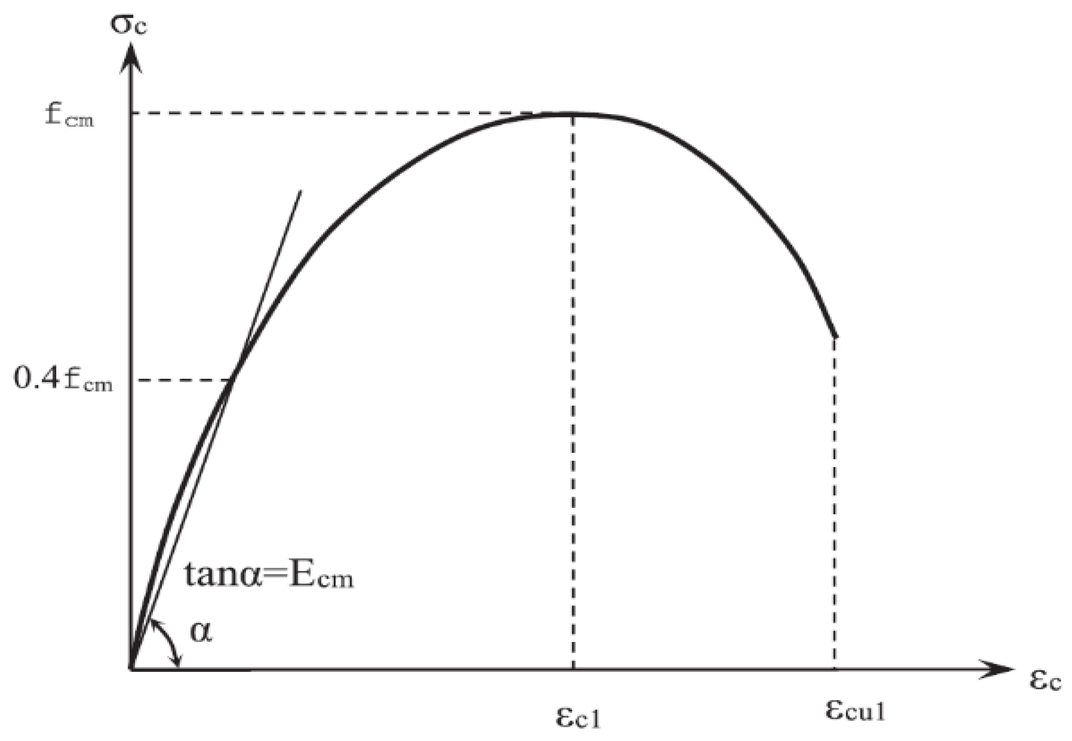
3.2.1. Concrete

The concrete slabs were analyzed using a damaged plasticity model [41]. To account for the distinct evolution of strength under tension and compression, Lee and Fenves [42] presented improvements to the model, which used the yield function of Lubliner et al. [43]. To model load transfer across cracks through the rebar, some “tension stiffening” was added to the concrete softening behavior. This indirectly took into account the structural elements of the rebar–concrete interaction, such as bond slip and dowel action. The uniaxial stress–strain relationship of the concrete used in this investigation is displayed in Figure 9.
The material model outlined in Eurocode 2, Part 1.1 [44], was adjusted to account for the first linear elastic response of concrete under compression, up to 40% of the mean compressive strength. The concrete’s highest compressive strength was determined to be its mean strength. The tensile strength was used as the Eurocode 2 lower bound [44].

3.2.2. Steel Reinforcement and FRP Sheets

The stress–strain findings of the uniaxial tensile tests were used to specify the steel reinforcement [45]. A bi-linear curve (linear elastic with strain hardening) was used to characterize the behavior. The steel reinforcement’s elastic modulus varied from 190 to 192 GPa. The range of yield stress was 570–576 MPa. The CFRP plates were believed to have a linear elastic orthotropic constitutive relation. The manufacturer supplied and experimentally verified the CFRP plates’ elastic longitudinal modulus, Ex, and tensile strength [44]. The CFRP plates’ other material characteristics, such as their shear modulus (Gxy) and elastic modulus (Ey) perpendicular to the fibers, were assumed based on standard material parameters reported by Kollár and Springer [46].

3.2.3. Loading and Boundary Conditions

The loading strategy used in the real tests was reflected in the load history for the FE model. It consisted of the following three primary steps:
  • To disperse the load over the supporting area and enable the slab corners to lift, the supports were designed as a rigid surface.
  • Release constraints: This step was a consequence of the previous step.
  • Loading: This was displacement-based until failure occurred, while the upper limit of the displacement values was chosen so that the entire load–deflection plateau, including the pre-and post-failure regions, could be captured.
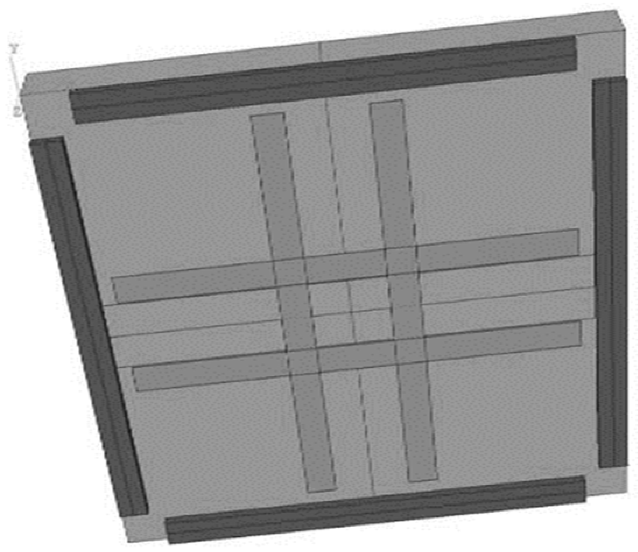
  • As shown in Figure 1, the corners of the slab were free to raise, and the slab’s perimeter was only held horizontally. The slab perimeter was supported by a solid surface that extended 1600 mm into the slab. The stress state surrounding the column region could be effectively captured, thanks to this boundary condition representation.

4. Results and Discussions

In experimental specimens, cracks are produced in concrete when the applied tensile stress exceeds the tensile strength of concrete. Therefore, cracks in the numerical specimens can be visualized by assuming that the cracks are produced at points where the tensile stresses exceed the tensile strength of the concrete. The comparison between the experimental and numerical results of the specimens without CFRP is shown in Figure 10. Figure 11 shows the distribution of numerical cracks. Due to the high tensile strains in the middle of the specimens, the cracks were concentrated in this region. The pattern of numerical cracks was similar to that of the experimental pattern.
Due to differences in the concrete mix, CFRP characteristics, and bond behavior, the assumed material parameters used in the numerical model may not match the actual properties of the experimental specimens. A slightly reduced numerical stiffness may result from complicated processes that the FEM may not fully capture, such as microcracking, bond–slip interactions between the CFRP and concrete, and plasticity effects. The numerical model might not accurately capture the small shortcomings of support settlements and loading application changes that are frequently present in experimental setups.
Moreover, the comparison between the numerical and experimental load–deflection relationships of specimens without CFRP is shown in Figure 11. The load–deflection relationships show a good agreement between the numerical and experimental results. However, the experimental load–deflection relationship was stiffer than that produced numerically. The maximum numerical deflection and experimental deflection were 32 mm and 35 mm, respectively. For the failure load, the maximum numerical load and experimental load were 295 kN and 282 kN, respectively. It was observed that the nonlinear behavior of the experimental specimen began at approximately 80 kN, while that of the numerical specimen started after 135 kN.
Figure 12 shows the numerical results of the specimens with CFRP. Figure 12 shows the distribution of numerical cracks. Due to the high tensile strains in the middle of the specimens, the cracks were concentrated in this region. The pattern of numerical cracks was similar to that of the experimental pattern. The use of CFRP reduced the number of cracks and the crack width.
The comparison between the numerical and experimental load–deflection relationships of the specimens with CFRP is shown in Figure 13. The load–deflection relationships show a good agreement between the numerical and experimental results. However, the numerical load–deflection relationship was slightly stiffer than that produced experimentally. The maximum numerical deflection and experimental deflection were 22 mm and 23 mm, respectively. For the failure load, the maximum numerical load and experimental load were 427 kN and 402 kN, respectively. One of the reasons for the difference between the numerical and experimental results was microcracking at the interfaces between the cement paste and aggregate [47,48]. This microcracking was produced in the concrete of the experimental specimens due to drying shrinkage, while these microcracks were not present in the numerical specimens [49]. It was shown that the nonlinear behavior of the experimental specimen started after about 75 kN, while in the numerical specimen, it started after 150 kN.
The numerical results of the proposed model indicate a good agreement with the experimental results. Therefore, the proposed model was adopted to study the projected groups of specimens. Figure 14 shows the numerical load–deflection relationship for the first group of specimens in comparison with the specimen without CFRP. The use of CFRP improved the behavior of the load–deflection relationship. In comparison with the specimen without CFRP (s1), the ultimate loads of the specimens (s3, s4, and s6) were increased up to 399 kN, 386 kN, and 392 kN, respectively. In addition to having the greatest ultimate load, the ultimate deflection of specimen s2 was greater than the others. It was also shown that the nonlinear behavior of the specimens without CFRP started after about 100 kN, while that of the specimens with CFRP started after 150 kN.
Figure 15 shows the numerical load–deflection relationship for the second group of specimens in comparison with the specimen without CFRP. The use of CFRP improved the behavior of the load–deflection relationship. In comparison with the specimen without CFRP (s1), the ultimate loads of the specimens (s2, s5, and s10) were increased up to 428 kN, 452 kN, and 450 kN, respectively. In comparison with the specimen without CFRP (s1), the ultimate loads were increased by 35% for the specimens with CFRP. The ultimate deflection of specimen S5 was greater than the others with CFRP. The use of CFRP reduced the ultimate deflection of the specimens at failure.
Figure 16 shows the numerical load–deflection relationship for the third group of specimens in comparison with the specimen without CFRP. The behavior of the load–deflection relationship was improved by using CFRP. In comparison with the specimen without CFRP (s1), the ultimate loads of the specimens (s8, s9, and s12) were increased up to 463 kN, 419 kN, and 477 kN, respectively. In addition to having the greatest ultimate load, the ultimate deflection of specimen S12 was greater than the others with CFRP. The deflection at the failure of s12 was more than 5 mm, more than that of the other specimens with CFRP.
Figure 17 shows the numerical load–deflection relationship for the fourth group of specimens in comparison with the specimen without CFRP. The use of CFRP improved the behavior of the load–deflection relationship. In comparison with the specimen without CFRP (s1), the ultimate loads of the specimens (s7, s11, s14, s15, and s16) were increased up to 432 kN, 487 kN, 434 kN, 429 kN, and 453 kN, respectively. In addition to having the greatest ultimate load, the ultimate deflection of specimen S11 was greater than the others with CFRP. All specimens with CFRP resulted in the same behavior until 200 kN; then, the specimens started having different behaviors with the applied loads.
Figure 18 shows the numerical load–deflection relationship for the fifth group of specimens in comparison with the specimen without CFRP. The use of CFRP improved the behavior of the load–deflection relationship. In comparison with the specimen without CFRP (s1), the ultimate load of the specimen (s16) was increased up to 432 kN. The ultimate deflection of specimen S16 was less than that of specimen S1 by 58%. It was also shown that the nonlinear behavior of the specimen with CFRP (s16) started after 160 kN.
Figure 19 shows the ultimate loads for the specimens reinforced with different ratios of CFRP in comparison with the specimens without CFRP. The use of CFRP improved the ultimate loads of the specimens. In comparison with the specimen without CFRP (S1), the ultimate loads were increased by 35%, 53%, 61%, 65%, and 46% for the specimens with CFRP ratios of 0.0444, 0.0888, 0.013, 0.177, and 0.222, respectively. The ultimate load of the specimens with a higher CFRP ratio produced a higher ultimate load until a 0.177 CFRP ratio. The specimen with a 0.177 CFRP ratio produced the greatest ultimate load in comparison with the other specimens. The use of a CFRP ratio of more than 0.177 reduced the ultimate load of the specimens.

5. Conclusions

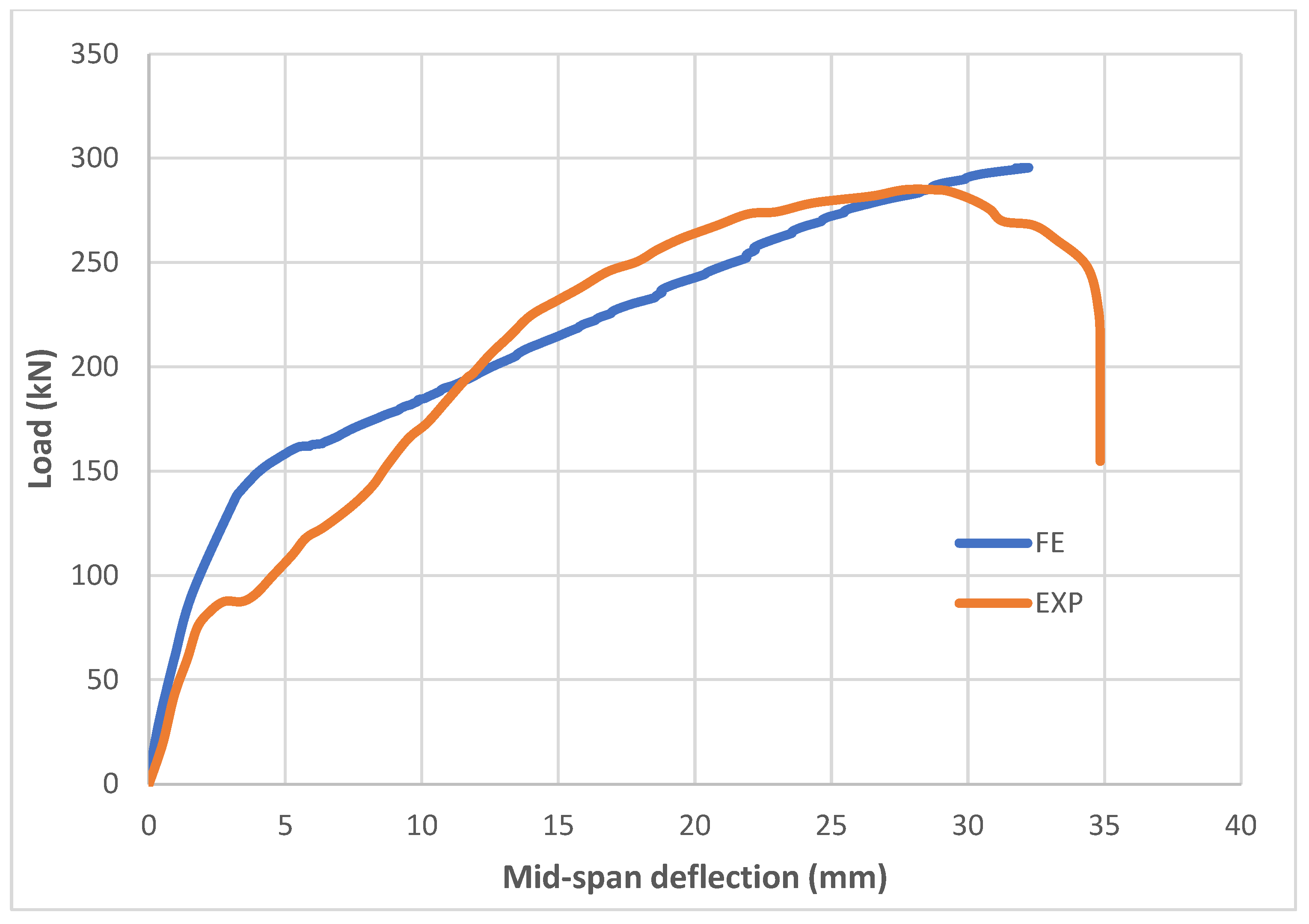
  • The proposed numerical model showed good agreement with the experimental results, demonstrating that the use of CFRP significantly improved the load–deflection behavior by increasing the ultimate loads. The numerical simulation demonstrated a reliable prediction of crack patterns, with both the experimental and numerical results showing cracks concentrated in the middle region due to high tensile strains. The load–deflection relationships exhibited good agreement, though the experimental specimens were slightly stiffer.
  • The maximum deflection and failure load were marginally higher in the experimental specimens (35 mm and 282 kN) compared with the numerical results (32 mm and 295 kN). Additionally, nonlinear behavior was initiated earlier in the experimental specimens (80 kN) than in the numerical ones (135 kN), suggesting the numerical model may overestimate stiffness during early loading stages. The numerical and experimental load–deflection relationships for the specimens with CFRP showed good agreement, with slight differences in their stiffness, deflection (22 mm vs. 23 mm), and failure load (427 kN vs. 402 kN).
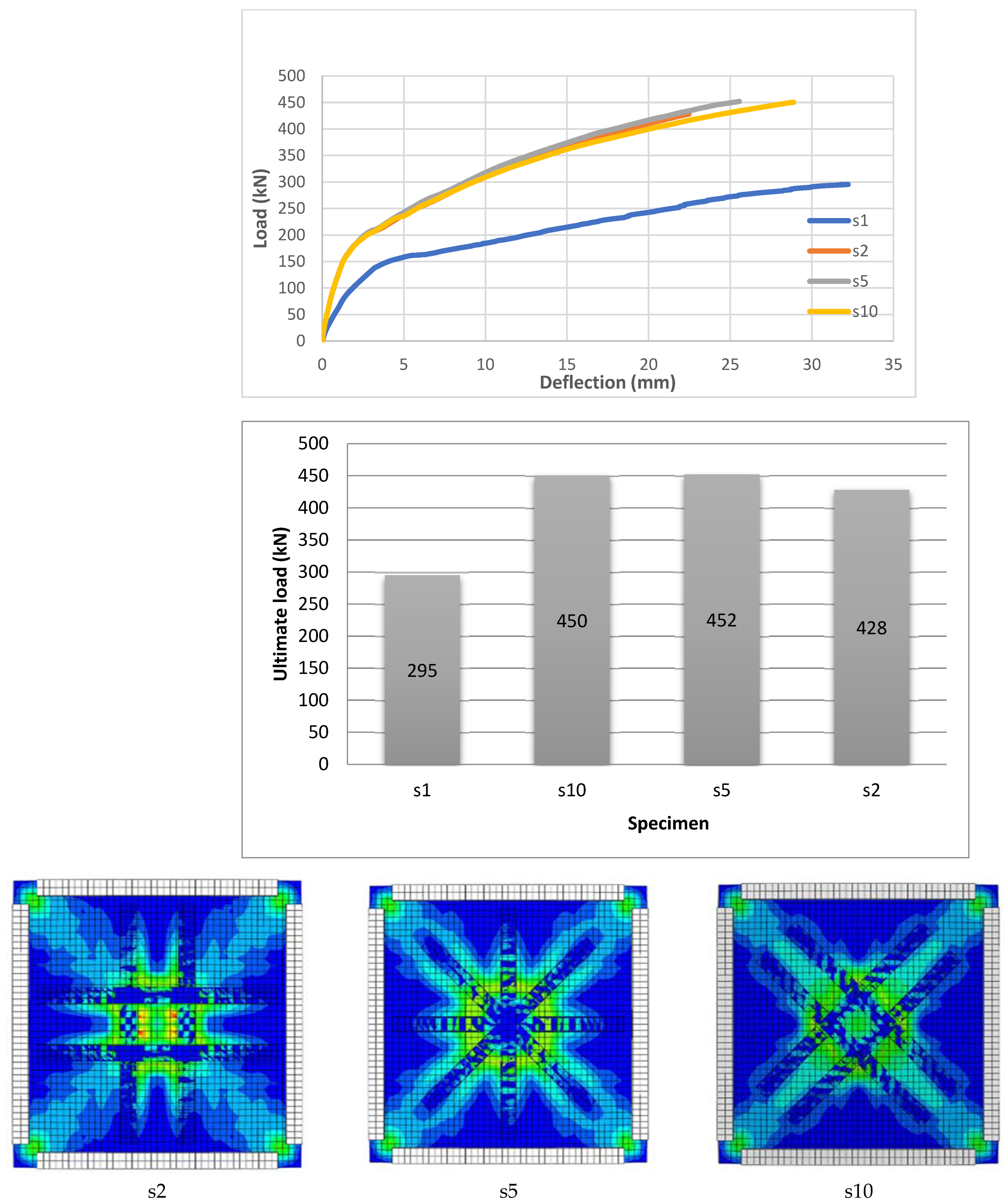
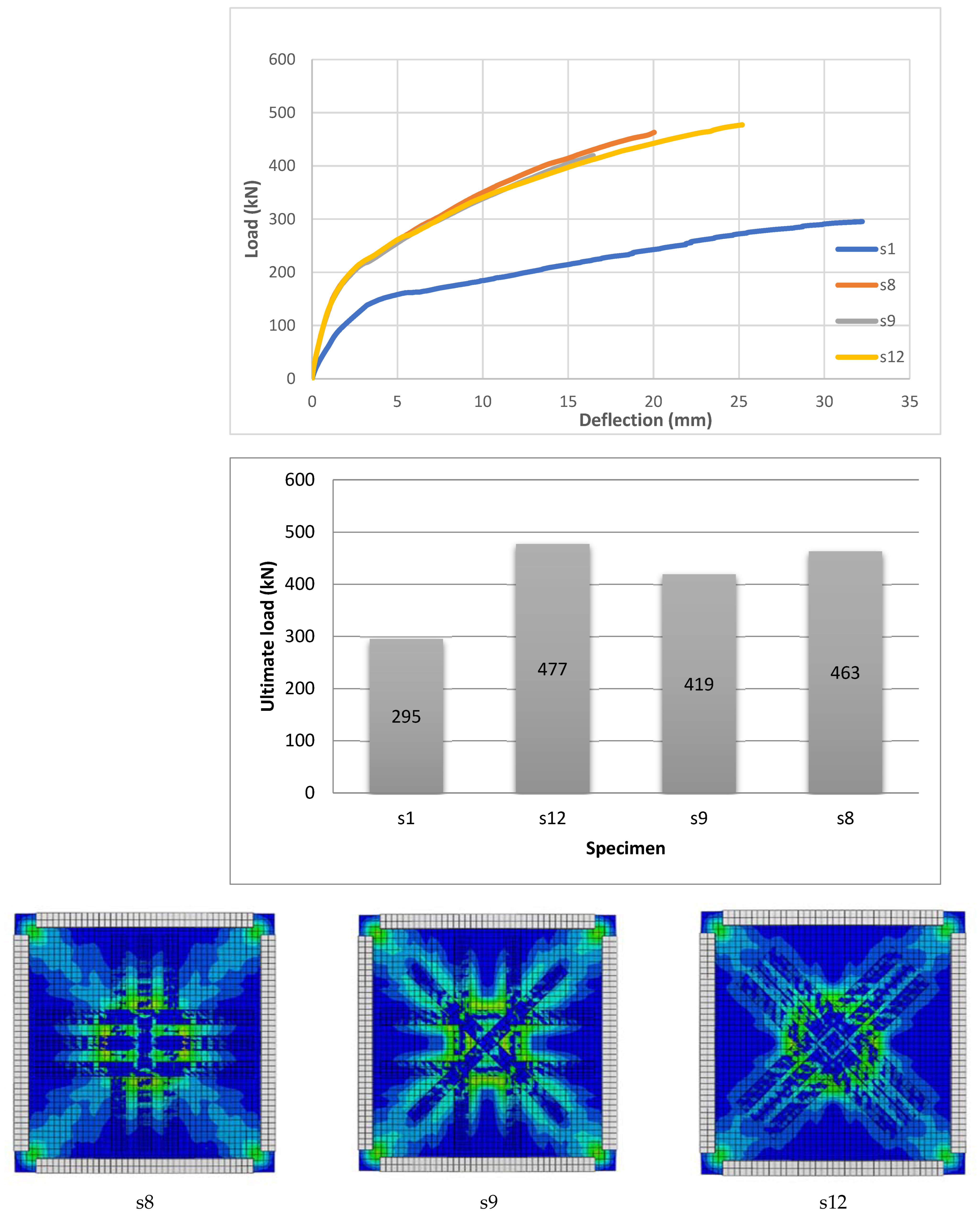
  • The use of CFRP significantly improved the load–deflection behavior, increasing the ultimate loads by 35% (e.g., 452 kN for S5) compared with the specimen without CFRP (s1) while reducing the ultimate deflection at failure, with S5 achieving the highest deflection among the CFRP specimens. When compared with the other CFRP specimens at failure, S12 had the biggest ultimate load and a deflection that was more than 5 mm larger. Compared with the specimen without CFRP (s1), the addition of CFRP enhanced the load–deflection behavior and increased the ultimate loads (e.g., 477 kN for s12).
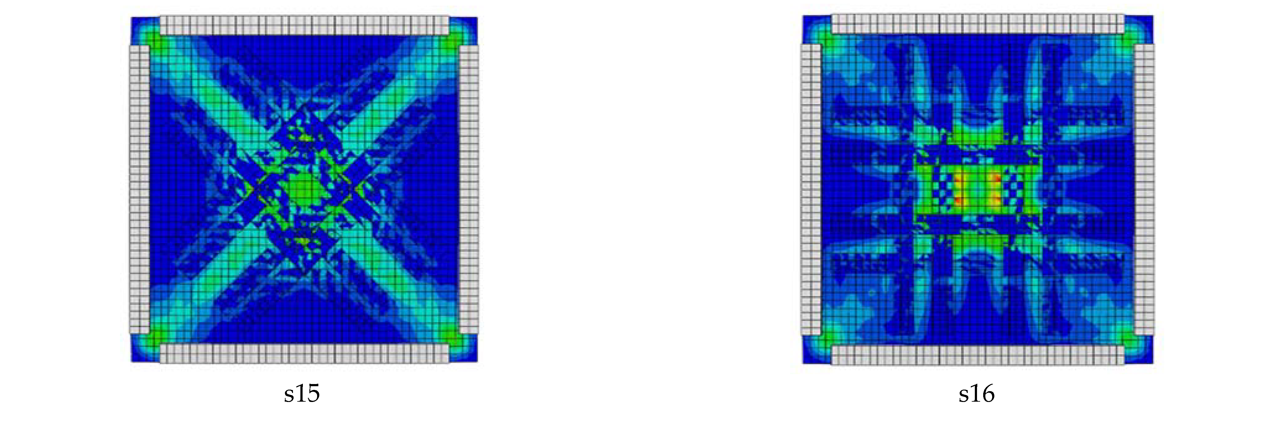
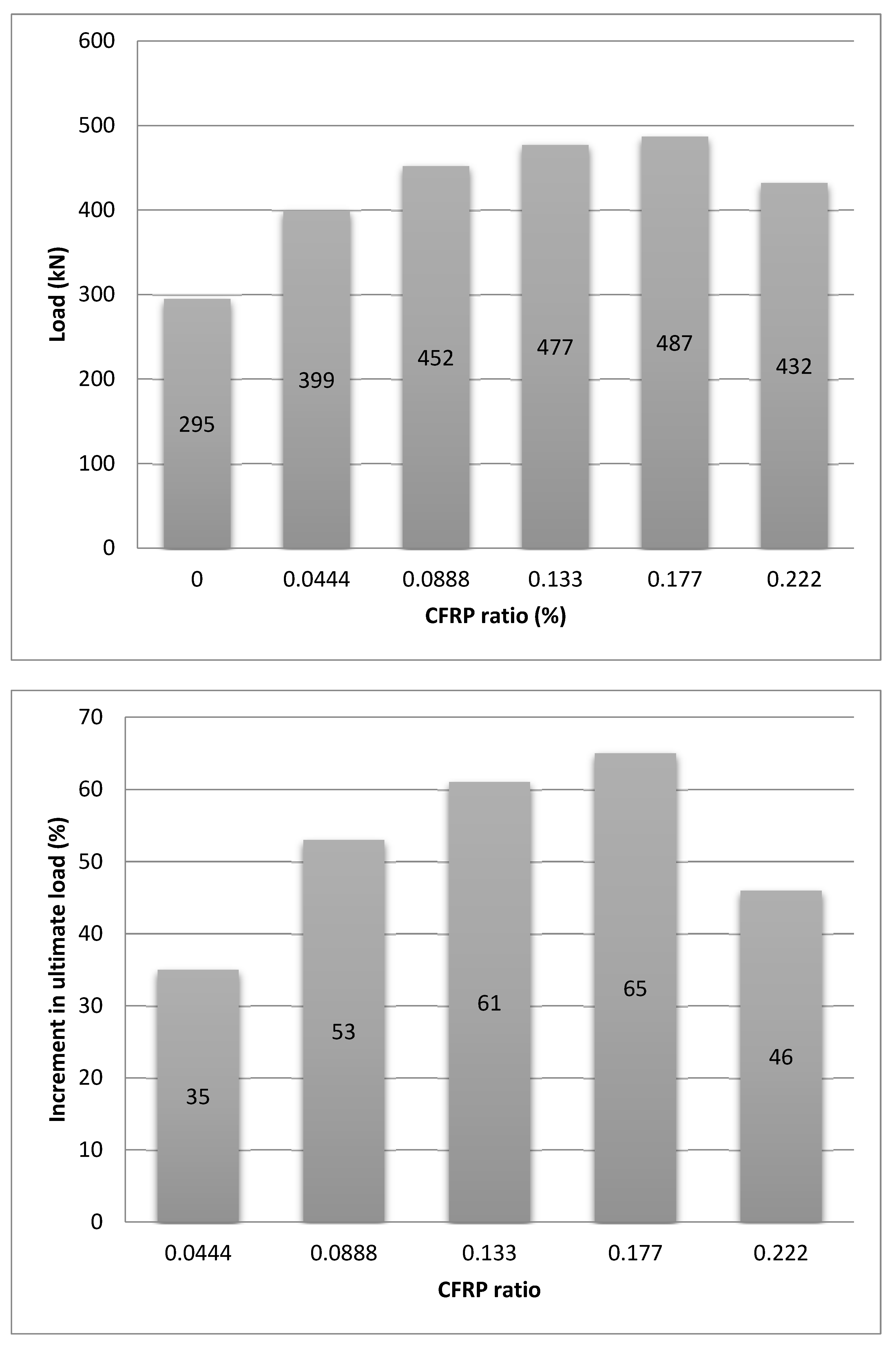
  • All CFRP specimens showed comparable behavior up to 200 kN before diverging at larger loads, although specimen s11 achieved the maximum ultimate load (487 kN) and deflection, demonstrating the improved load–deflection behavior brought about by CFRP use. The CFRP application’s improved load–deflection behavior caused specimen s16’s ultimate load to increase to 432 kN. But at around 160 kN, nonlinear behavior started to show, and its ultimate deflection was 58% less than that of specimen s1. The use of CFRP increased the ultimate loads by up to 65%, with the highest load achieved at a CFRP ratio of 0.177, while ratios above 0.177 reduced the ultimate load.
  • Optimizing CFRP strengthening configurations, considering factors like plate placement, orientation, and strengthening percentages based on load and slab specifications, along with following guidelines for surface preparation, bonding conditions, and curing times, will ensure effective application; furthermore, the selection of CFRP systems for retrofitting RC structures should consider cost, material compatibility, and environmental conditions, while addressing real-world challenges, such as handling large CFRP sheets and achieving uniform bonding on irregular surfaces.

6. Design Recommendations and Applications

To ensure the proper application of CFRP strengthening, the selection of CFRP plate patterns and strengthening percentages should align with specific structural performance requirements, considering factors like flexural capacity, stiffness, and failure mechanisms. Key aspects such as debonding risks, stress concentrations, and correct installation techniques must be carefully managed to guarantee success. Achieving the best bonding and load transfer necessitates meticulous surface preparation, an appropriate adhesive choice, and controlled curing processes. Additionally, long-term durability should be assessed by evaluating the environmental exposure and potential degradation of the CFRP material over time.

Author Contributions

Conceptualization, A.A.-Y. and H.A.L.; methodology, Y.A.A.; software, Y.A.A.; writing—original draft preparation, Y.A.A. and R.S.K.; writing—review and editing, Y.S.S.A.-K. and L.N.A.; supervision, H.C.D. All authors have read and agreed to the published version of the manuscript.

Funding

This research received no external funding.

Data Availability Statement

The raw data supporting the conclusions of this article will be made available by the authors on request.

Conflicts of Interest

Author Lateef N. Assi was employed by the company A Terracon Consultants Inc. The remaining authors declare that the research was conducted in the absence of any commercial or financial relationships that could be construed as a potential conflict of interest.

References

  1. Jones, A.E.K.; Morrison, J. Flat slab design: Past, present and future. Proc. Inst. Civ. Eng.-Struct. Build. 2005, 158, 133–140. [Google Scholar] [CrossRef]
  2. Sagban, S.A.A.; Abbas, M.; Hussain, H.K. A Review on Flat Slab Punching Shear Reinforcement. J. Univ. Babylon Eng. Sci. 2019, 27, 44–58. [Google Scholar]
  3. Lapi, M.; Ramos, A.P.; Orlando, M. Flat slab strengthening techniques against punching-shear. Eng. Struct. 2019, 180, 160–180. [Google Scholar] [CrossRef]
  4. Saleh, H.; Abdouka, K.; Al-Mahaidi, R.; Kalfat, R. Strengthening of slab–column connections against punching shear using FRP materials: State-of-the-art review. Aust. J. Struct. Eng. 2018, 19, 188–206. [Google Scholar] [CrossRef]
  5. Amiri, S.; Talaeitaba, S.B. Punching shear strengthening of flat slabs with EBROG and EBRIG—FRP strips. Structures 2020, 26, 139–155. [Google Scholar] [CrossRef]
  6. Inácio, M.M.G.; Ramos, A.P.; Faria, D.M.V. Strengthening of flat slabs with transverse reinforcement by introduction of steel bolts using different anchorage approaches. Eng. Struct. 2012, 44, 63–77. [Google Scholar] [CrossRef]
  7. Yaman, S.S.A.-K.; Abdulhameed, A.Y.; Mezgeen, S.A.; Ferhadi, R.; Mand, K.A. Predicting strength and strain of circular concrete cross-sections confined with FRP under axial compression by utilizing artificial neural networks. Comput. Concr. 2024, 34, 93–122. [Google Scholar]
  8. Mohamed, O.A.; Kewalramani, M.; Khattab, R. Fiber Reinforced Polymer Laminates for Strengthening of RC Slabs against Punching Shear: A Review. Polymers 2020, 12, 685. [Google Scholar] [CrossRef]
  9. Abdullah, A.M. Analysis of Repaired/Strengthened RC Structures Using Composite Materials: Punching Shear; The University of Manchester: Manchester, UK, 2011. [Google Scholar]
  10. Oehlers, D.J.; Liu, I.; Seracino, R. Shear deformation debonding of adhesively bonded plates. Proc. Inst. Civ. Eng.-Struct. Build. 2005, 158, 77–84. [Google Scholar] [CrossRef]
  11. Teng, J.; Chen, J. Debonding failures of RC beams strengthened with externally bonded FRP reinforcement: Behaviour and modelling. In Proceedings of the First Asia-Pacific Conference on FRP in Structures (APFIS 2007), The University of Hong Kong, Hong Kong, China, 12–14 December 2007; pp. 12–14. [Google Scholar]
  12. Shiyal, H.W.; Jawad, D.A. Strengthening of flat slab with openings under punching shear load. Univ. Thi-Qar J. Eng. Sci. 2022, 12, 174–183. [Google Scholar] [CrossRef]
  13. Ueda, T.; Dai, J. Interface bond between FRP sheets and concrete substrates: Properties, numerical modeling and roles in member behaviour. Prog. Struct. Eng. Mater. 2005, 7, 27–43. [Google Scholar] [CrossRef]
  14. Daneshvar, D.; Behnood, A.; Robisson, A. Interfacial bond in concrete-to-concrete composites: A review. Constr. Build. Mater. 2022, 359, 129195. [Google Scholar] [CrossRef]
  15. Abdullah, A.; Bailey, C.G. Punching behaviour of column-slab connection strengthened with non-prestressed or prestressed FRP plates. Eng. Struct. 2018, 160, 229–242. [Google Scholar] [CrossRef]
  16. Cheng, H.T.; Mohammed, B.S.; Mustapha, K.N. Finite element analysis and structural design of pretensioned inverted T-beams with web openings. Front. Archit. Civ. Eng. China 2009, 3, 148–157. [Google Scholar] [CrossRef]
  17. Alsaeq, H.M. Effects of opening shape and location on the structural strength of RC deep beams with openings. Int. J. Civ. Environ. Eng. 2013, 7, 494–499. [Google Scholar]
  18. Hassan, H.M.; Arab, M.A.E.S.; Ismail El-Kassas, A. Behavior of high strength self compacted concrete deep beams with web openings. Heliyon 2019, 5, e01524. [Google Scholar] [CrossRef]
  19. Ali, Y.A.; Assi, L.N.; Abas, H.; Taresh, H.R.; Dang, C.N.; Ghahari, S. Numerical Investigation on Effect of Opening Ratio on Structural Performance of Reinforced Concrete Deep Beam Reinforced with CFRP Enhancements. Infrastructures 2022, 8, 2. [Google Scholar] [CrossRef]
  20. Zhang, Z.; Zhao, T.; Wang, X. Mesoscale modelling of concrete damage in FRP-concrete debonding failure. Eng. Struct. 2023, 289, 116310. [Google Scholar] [CrossRef]
  21. Lu, X.Z.; Teng, J.G.; Ye, L.P.; Jiang, J.J. Bond–slip models for FRP sheets/plates bonded to concrete. Eng. Struct. 2005, 27, 920–937. [Google Scholar] [CrossRef]
  22. Lu, X.Z.; Jiang, J.J.; Teng, J.G.; Ye, L.P. Finite element simulation of debonding in FRP-to-concrete bonded joints. Constr. Build. Mater. 2006, 20, 412–424. [Google Scholar] [CrossRef]
  23. Richard, C.E.; Eivind, H. Shearing Strength of Reinforced Concrete Slabs. ACI J. Proc. 1956, 53, 29–58. [Google Scholar]
  24. Amin, G. An Efficient Solution to Punching of Slabs. Concr. Int. 1989, 11, 50–54. [Google Scholar]
  25. Ebead, U.; Marzouk, H. Strengthening of Two-Way Slabs Using Steel Plates. ACI Struct. J. 2002, 99, 23–31. [Google Scholar]
  26. El-Salakawy, M.A.P.E.F.; Khaled, A.S. New Shear Strengthening Technique for Concrete Slab-Column Connections. ACI Struct. J. 2003, 100, 297–304. [Google Scholar]
  27. Kyriakos, S.; Shamim, A.S. Strengthening Concrete Slabs for Punching Shear with Carbon Fiber-Reinforced Polymer Laminates. ACI Struct. J. 2007, 104, 49. [Google Scholar]
  28. Binici, B.; Bayrak, O. Punching Shear Strengthening of Reinforced Concrete Flat Plates Using Carbon Fiber Reinforced Polymers. J. Struct. Eng. 2003, 129, 1173–1182. [Google Scholar] [CrossRef]
  29. Baris, B.; Oguzhan, B. Use of Fiber-Reinforced Polymers in Slab-Column Connection Upgrades. ACI Struct. J. 2005, 102, 93. [Google Scholar]
  30. Erki, M.A.; Heffernan, P.J. Reinforced concrete slabs externally strengthened with fibre-reinforced plastic materials. In Proceedings of the 2nd Symposium on Non-Metalic FRP Reinforcement for Concrete Structures (FRPRCS-2), Ghent, Belgium, 23–25 August 1995. [Google Scholar]
  31. Harajli, M.H.; Soudki, K.A. Shear Strengthening of Interior Slab–Column Connections Using Carbon Fiber-Reinforced Polymer Sheets. J. Compos. Constr. 2003, 7, 145–153. [Google Scholar] [CrossRef]
  32. Sharaf, M.H.; Soudki, K.A.; Dusen, M.V. CFRP Strengthening for Punching Shear of Interior Slab–Column Connections. J. Compos. Constr. 2006, 10, 410–418. [Google Scholar] [CrossRef]
  33. Kalfat, R.; Al-Mahaidi, R. Numerical and Experimental Validation of FRP Patch Anchors Used to Improve the Performance of FRP Laminates Bonded to Concrete. J. Compos. Constr. 2014, 18, A4013008. [Google Scholar] [CrossRef]
  34. El-Maaddawy, T.A.; Sherif, E.-S.I. Response of Concrete Corbels Reinforced with Internal Steel Rebars and External Composite Sheets: Experimental Testing and Finite Element Modeling. J. Compos. Constr. 2014, 18, 04013020. [Google Scholar] [CrossRef]
  35. Gouda, A.; El-Salakawy, E. Punching Shear Strength of GFRP-RC Interior Slab–Column Connections Subjected to Moment Transfer. J. Compos. Constr. 2016, 20, 04015037. [Google Scholar] [CrossRef]
  36. Salama, A.E.; Hassan, M.; Benmokrane, B. Effect of GFRP Shear Stirrups on Strength of Two-Way GFRP RC Edge Slabs: Experimental and Finite-Element Investigations. J. Struct. Eng. 2020, 146, 04020056. [Google Scholar] [CrossRef]
  37. El-Gendy, M.G.; El-Salakawy, E.F. Finite-Element Analysis of FRP-Reinforced Concrete Slab–Column Edge Connections Subjected to Reversed-Cyclic Lateral Loads. J. Compos. Constr. 2021, 25, 04020082. [Google Scholar] [CrossRef]
  38. Ali, Y.A.; Falah, M.W.; Naser, M.H. Finite Element Analysis of Beams Strengthened in Flexure with Carbon Fiber Reinforced Polymer Plates. AIP Conf. Proc. 2023, 2787, 080029. [Google Scholar] [CrossRef]
  39. Ali, Y.A.; Falah, M.W.; Ali, A.H.; Al-Mulali, M.Z.; AL-Khafaji, Z.S.; Hashim, T.M.; Sa’adi, A.H.M.A.; Al-Hashimi, O. Studying the Effect of Shear Stud Distribution on the Behavior of Steel–Reactive Powder Concrete Composite Beams Using ABAQUS Software. J. Mech. Behav. Mater. 2022, 31, 416–425. [Google Scholar] [CrossRef]
  40. ASTM D3039/D3039M; Standard Test Method for Tensile Properties of Polymer Matrix Composites Materials. Annual Book of ASTM Standards: West Conshohocken, PA, USA, 2008.
  41. Hibbitt, K.; Sorensen, I. ABAQUS Theory Manual, User Manual and Example Manual, version 6.7; Simulia: Providence, RI, USA, 2000. [Google Scholar]
  42. Lee, J.; Fenves, G.L. A return-mapping algorithm for plastic-damage models: 3-D and plane stress formulation. Int. J. Numer. Methods Eng. 2001, 50, 487–506. [Google Scholar] [CrossRef]
  43. Lubliner, J.; Oliver, J.; Oller, S.; Onate, E. A plastic-damage model for concrete. Int. J. Solids Struct. 1989, 25, 299–326. [Google Scholar] [CrossRef]
  44. Eurocode 2. Eurocode 2: Design of concrete structures-part 1–1: General rules and rules for buildings, British Standard Institution. London 2005, 668, 659–668. [Google Scholar]
  45. Hafezolghorani, M.; Hejazi, F.; Vaghei, R.; Jaafar, M.S.B.; Karimzade, K. Simplified Damage Plasticity Model for Concrete. Struct. Eng. Int. 2017, 27, 68–78. [Google Scholar] [CrossRef]
  46. Kollar, L.P. Mechanics of Composite Structures; Cambridge University Press: Cambridge, UK, 2003. [Google Scholar]
  47. Aminpour, N.; Memari, A. Numerical and experimental study on reinforced 3DCP walls filled with light-weight concrete. J. Build. Eng. 2024, 97, 110995. [Google Scholar] [CrossRef]
  48. Kareem, R.S.; Assi, L.N.; Alsalman, A.; Al-Manea, A. Effect of supplementary cementitious materials on RC concrete piles. In AIP Conference Proceedings; October AIP Publishing: Long Island, NY, USA, 2021; Volume 2404. [Google Scholar]
  49. Assi, L.N.; Alsalman, A.; Al-Hamadani, Y.A.; Kareem, R.; Khuzaie, H.M.A.A. September. Observations of Supplementary Cementitious Materials Effects on The Performance of Concrete Foundation. In IOP Conference Series: Earth and Environmental Science; IOP Publishing: Long Island, NY, USA, 2021; Volume 856, p. 012020. [Google Scholar]
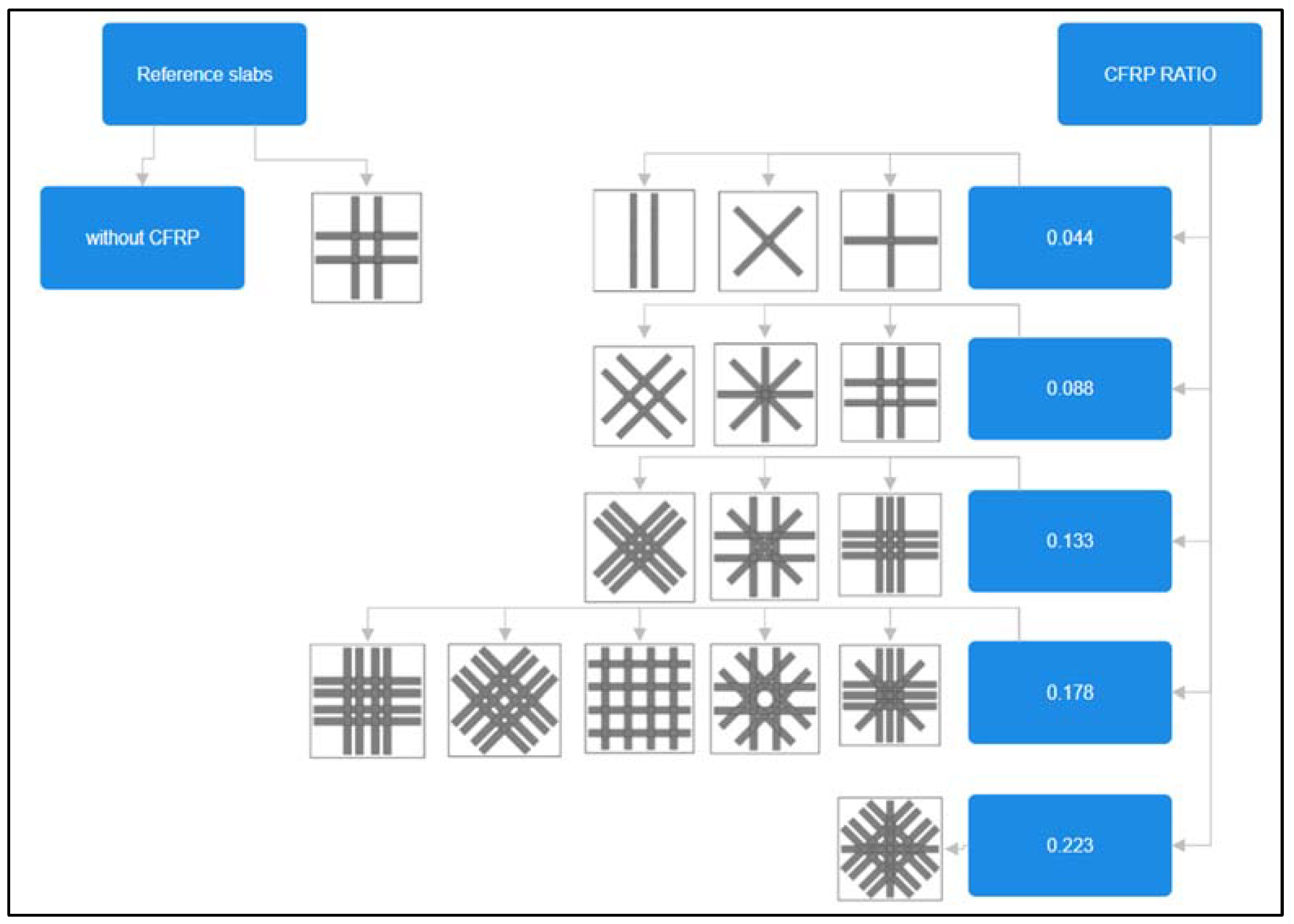
Figure 1. Numerical study undertaken by Abdullah [9].
Constrmater 05 00024 g001
Figure 2. Sample flowchart.
Constrmater 05 00024 g002
Figure 3. CFRP arrangement of group 1 specimens.
Constrmater 05 00024 g003
Figure 4. CFRP arrangement of group 2 specimens.
Constrmater 05 00024 g004
Figure 5. CFRP arrangement of group 3 specimens.
Constrmater 05 00024 g005
Figure 6. CFRP arrangement of group 4 specimens.
Constrmater 05 00024 g006
Figure 7. CFRP arrangement of group 5 specimens.
Constrmater 05 00024 g007
Figure 8. A typical slab geometry.
Constrmater 05 00024 g008
Figure 9. Uniaxial stress–strain relationship of the concrete.
Constrmater 05 00024 g009
Figure 10. Crack pattern and stress distribution.
Constrmater 05 00024 g010
Figure 11. Load–deflection of control without CFRP.
Constrmater 05 00024 g011
Figure 12. Crack pattern and stress distribution.
Constrmater 05 00024 g012
Figure 13. Load–deflection of control with CFRP.
Constrmater 05 00024 g013
Figure 14. Load–deflection relationship and stress distributions of the first group.
Constrmater 05 00024 g014
Figure 15. Load–deflection relationship and stress distributions of the second group.
Constrmater 05 00024 g015
Figure 16. Load–deflection relationship and stress distributions of the third group.
Constrmater 05 00024 g016
Figure 17. Load–deflection relationship and stress distributions of the fourth group.
Constrmater 05 00024 g017aConstrmater 05 00024 g017b
Figure 18. Load–deflection relationship and stress distribution of the fifth group.
Constrmater 05 00024 g018
Figure 19. Ultimate load with different CFRP ratios.
Constrmater 05 00024 g019
Table 1. RC slab details.
Group
No.
Specimen
Code
CFRP
Ratio
FRP
Configuration
No. of CFRP PlatesNotes
Abdullah [9]RS0Reference slab-4Figure 1
RS-F0CFRPCross
1s30.044Cross2Figure 3
s4Augmentation
s6Longitudinal
2s20.088Cross4Figure 4
s5Cross-hatched
s10Cross-diagonal
3s80.133Cross6Figure 5
s9Cross-hatched
s12Cross-diagonal
4s70.178Cross-hatched8Figure 6
s11Cross-hatched
s13Grid patterns
s14Cross-diagonal
s15Cross
5s160.223Cross-diagonal10Figure 7
Disclaimer/Publisher’s Note: The statements, opinions and data contained in all publications are solely those of the individual author(s) and contributor(s) and not of MDPI and/or the editor(s). MDPI and/or the editor(s) disclaim responsibility for any injury to people or property resulting from any ideas, methods, instructions or products referred to in the content.

