
Simulation-Based Development of Gradient Woven Fabrics for Biomimetic Implants to Restore Tendons and Ligaments

 ,
,  , , , and
Abstract
:1. Introduction
1.1. General Considerations
1.2. Textile Materials for Use as Tendon or Ligament Implants
2. Materials and Methods
2.1. Material
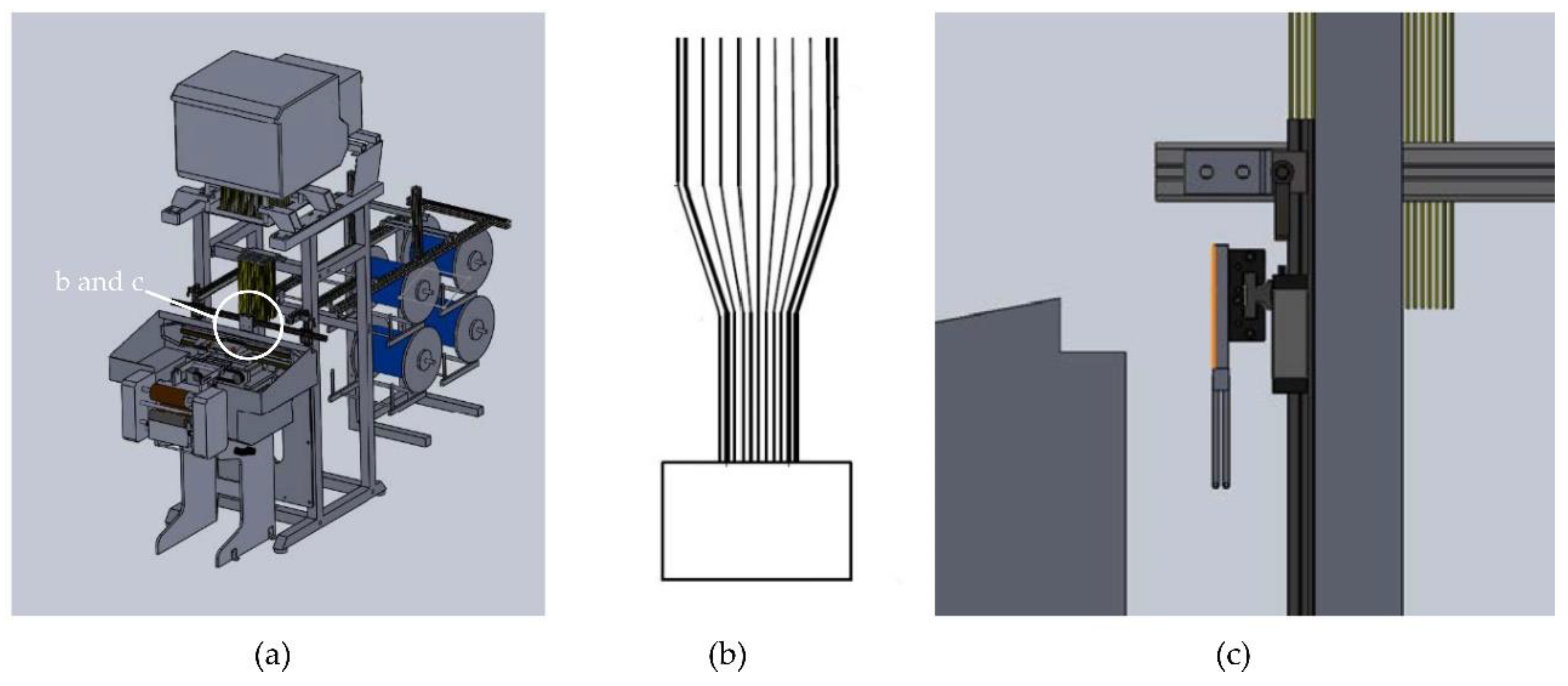
2.2. Weaving
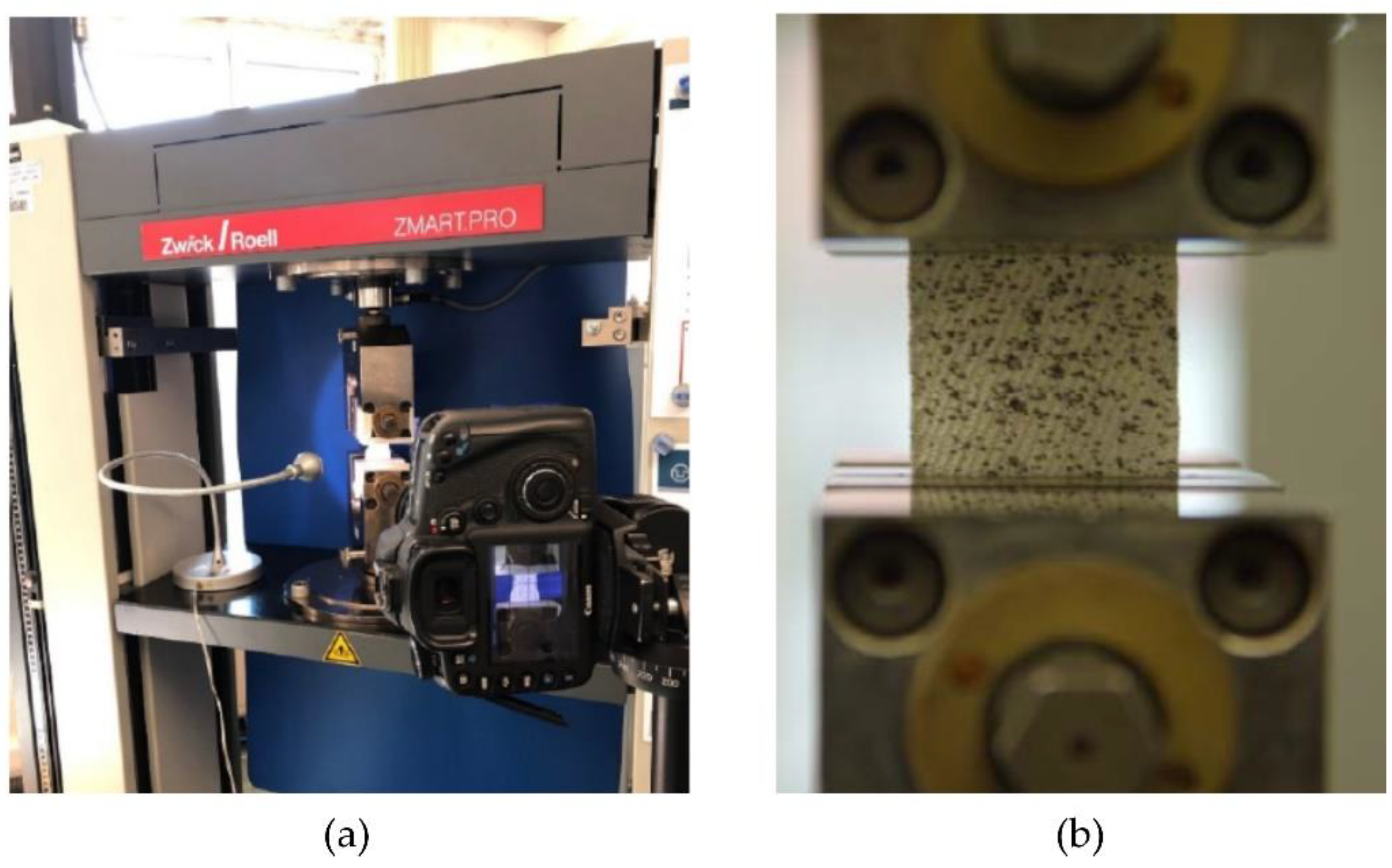
2.3. Testing
2.4. Modelling
3. Results and Discussion
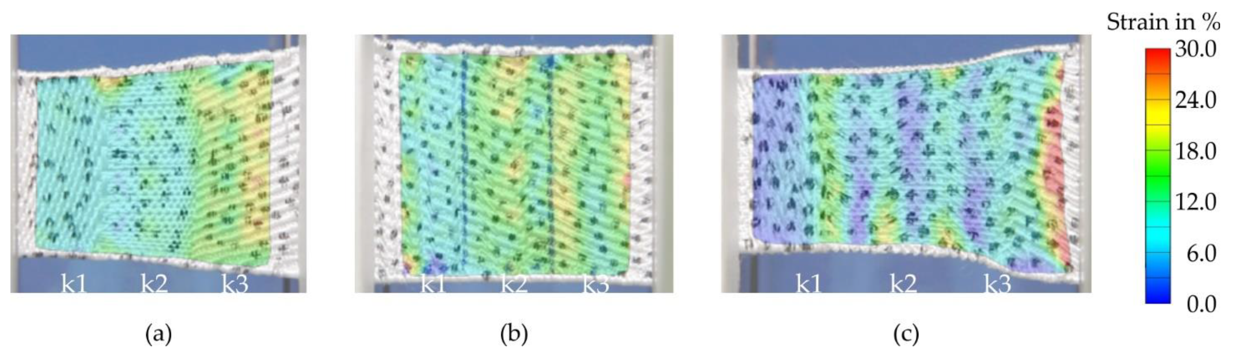
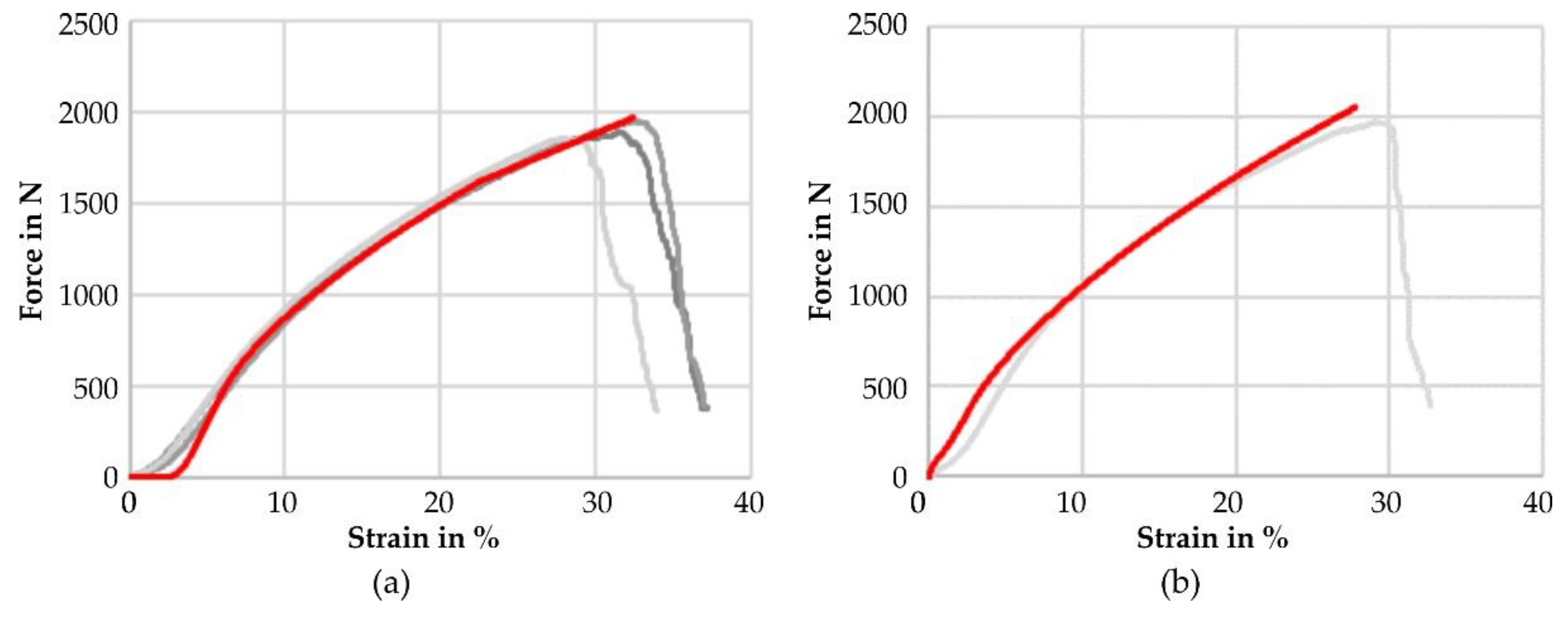
3.1. Testing
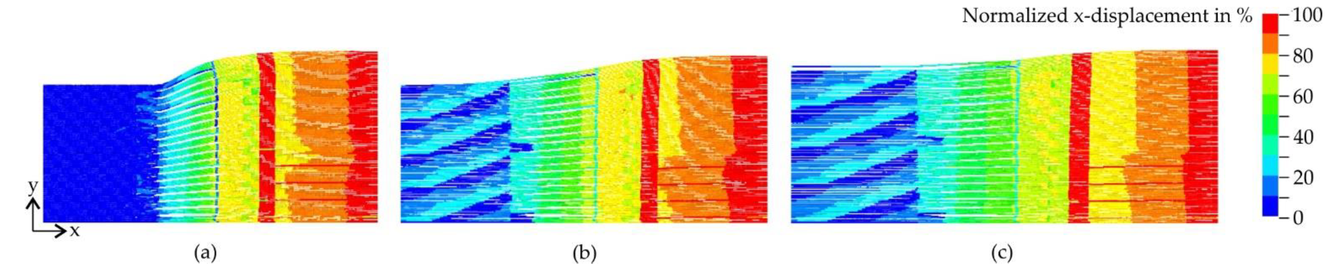
3.2. Modelling
4. Conclusions
Author Contributions
Funding
Data Availability Statement
Acknowledgments
Conflicts of Interest
References
- Kannus, P. Structure of the Tendon Connective Tissue. Scand. J. Med. Sci. Sport. 2000, 10, 312–320. [Google Scholar] [CrossRef]
- Vasconcelos, A.; Gomes, A.C.; Cavaco-Paulo, A. Novel Silk Fibroin/Elastin Wound Dressings. Acta Biomater. 2012, 8, 3049–3060. [Google Scholar] [CrossRef] [Green Version]
- Teuschl, A.H.; Van Griensven, M.; Redl, H. Sericin Removal from Raw Bombyx Mori Silk Scaffolds of High Hierarchical Order. Tissue Eng. Part C Methods 2014, 20, 431–439. [Google Scholar] [CrossRef] [PubMed]
- Fine, N.A.; Lehfeldt, M.; Gross, J.E.; Downey, S.; Kind, G.M.; Duda, G.; Kulber, D.; Horan, R.; Ippolito, J.; Jewell, M.; et al. SERI Surgical Scaffold, Prospective Clinical Trial of a Silk-Derived Biological Scaffold in Two-Stage Breast Reconstruction: 1-Year Data. Plast. Reconstr. Surg. 2015, 135, 339–351. [Google Scholar] [CrossRef]
- Wöltje, M.; Böbel, M. Natural Biodegradable Medical Polymers: Silk. In Science and Principles of Biodegradable and Bioresorbable Medical Polymers; Zhang, X., Ed.; Woodhead Publishing: Duxford, UK, 2017; pp. 351–376. [Google Scholar]
- Wöltje, M.; Kölbel, A.; Aibibu, D.; Cherif, C. A Fast and Reliable Process to Fabricate Regenerated Silk Fibroin Solution from Degummed Silk in 4 Hours. Int. J. Mol. Sci. 2021, 22, 10565. [Google Scholar] [CrossRef] [PubMed]
- Minoura, N.; Aiba, S.; Gotoh, Y.; Tsukada, M.; Imari, Y. Attachment and Growth of Fibroblast Cells on Silk Protein Matrices. J. Biomed. Mater. Res. 1995, 29, 1215–1221. [Google Scholar] [CrossRef]
- Dal Pra, I.; Freddi, G.; Minic, J.; Chiarini, A.; Armato, U. De Novo Engineering of Reticular Connective Tissue In Vivo by Silk Fibroin Nonwoven Materials. Biomaterials 2005, 26, 1987–1999. [Google Scholar] [CrossRef]
- Meinel, L.; Hofmann, S.; Karageorgiou, V.; Kirker-Head, C.; McCool, J.; Gronowicz, G.; Zichner, L.; Langer, R.; Vunjak-Novakovic, G.; Kaplan, D.L. The Inflammatory Responses to Silk Films In Vitro and In Vivo. Biomaterials 2005, 26, 147–155. [Google Scholar] [CrossRef] [PubMed]
- Kim, K.-H.; Jeong, L.; Park, H.-N.; Shin, S.-Y.; Park, W.-H.; Lee, S.-C.; Kim, T.-I.; Park, Y.-J.; Seol, Y.-J.; Lee, Y.-M.; et al. Biological Efficacy of Silk Fibroin Nanofiber Membranes for Guided Bone Regeneration. J. Biotechnol. 2005, 120, 327–339. [Google Scholar] [CrossRef]
- Cai, Z.X.; Mo, X.M.; Zhang, K.H.; Fan, L.P.; Yin, A.L.; He, C.L.; Wang, H.S. Fabrication of Chitosan/Silk Fibroin Composite Nanofibers for Wound-Dressing Applications. Int. J. Mol. Sci. 2010, 11, 3529–3539. [Google Scholar] [CrossRef] [PubMed]
- Liu, T.L.; Miao, J.C.; Sheng, W.H.; Xie, Y.F.; Huang, Q.; Shan, Y.B.; Yang, J.C. Cytocompatibility of Regenerated Silk Fibroin Film: A Medical Biomaterial Applicable to Wound Healing. J. Zhejiang Univ. Sci. B 2010, 11, 10–16. [Google Scholar] [CrossRef] [Green Version]
- Koh, L.D.; Cheng, Y.; Teng, C.P.; Khin, Y.W.; Loh, X.J.; Tee, S.Y.; Low, M.; Ye, E.; Yu, H.D.; Zhang, Y.W.; et al. Structures, Mechanical Properties and Applications of Silk Fibroin Materials. Prog. Polym. Sci. 2015, 46, 86–110. [Google Scholar] [CrossRef]
- Jao, D.; Mou, X.; Hu, X. Tissue Regeneration: A Silk Road. J. Funct. Biomater. 2016, 7, 22. [Google Scholar] [CrossRef]
- Shao, Z.; Vollrath, F. Surprising Strength of Silkworm Silk. Nature 2002, 418, 741. [Google Scholar] [CrossRef]
- Lu, H.H.; Cooper, J.A.; Manuel, S.; Freeman, J.W.; Attawia, M.A.; Ko, F.K.; Laurencin, C.T. Anterior Cruciate Ligament Regeneration Using Braided Biodegradable Scaffolds: In Vitro Optimization Studies. Biomaterials 2005, 26, 4805–4816. [Google Scholar] [CrossRef]
- Anand, S.C.; Kennedy, J.F.; Miraftab, M.; Rajendran, S. (Eds.) Medical Textiles and Biomaterials for Healthcare; Woodhead Publishing: Cambridge, UK, 2006; ISBN 9781855736832. [Google Scholar]
- Freeman, J.W.; Woods, M.D.; Laurencin, C.T. Tissue Engineering of the Anterior Cruciate Ligament Using a Braid-Twist Scaffold Design. J. Biomech. 2007, 40, 2029–2036. [Google Scholar] [CrossRef] [Green Version]
- Machotka, Z.; Scarborough, I.; Duncan, W.; Kumar, S.; Perraton, L. Anterior Cruciate Ligament Repair with LARS (Ligament Advanced Reinforcement System): A Systematic Review. Sport. Med. Arthrosc. Rehabil. Ther. Technol. 2010, 2, 1–10. [Google Scholar] [CrossRef] [Green Version]
- Walters, V.I.; Kwansa, A.L.; Freeman, J.W. Design and Analysis of Braid-Twist Collagen Scaffolds. Connect. Tissue Res. 2012, 53, 255–266. [Google Scholar] [CrossRef]
- Gereke, T.; Döbrich, O.; Aibibu, D.; Nowotny, J.; Cherif, C. Approaches for Process and Structural Finite Element Simulations of Braided Ligament Replacements. J. Ind. Text. 2017, 47, 408–425. [Google Scholar] [CrossRef]
- Mengsteab, P.Y.; Freeman, J.; Barajaa, M.A.; Nair, L.S.; Laurencin, C.T. Ligament Regenerative Engineering: Braiding Scalable and Tunable Bioengineered Ligaments Using a Bench-Top Braiding Machine. Regen. Eng. Transl. Med. 2021, 7, 524–532. [Google Scholar] [CrossRef] [PubMed]
- Sahoo, S.; Ouyang, H.; James, C.H.; Tay, T.E.; Toh, S.L. Characterization of a Novel Polymeric Scaffold for Potential Application in Tendon/Ligament Tissue Engineering. Tissue Eng. 2006, 12, 91–99. [Google Scholar] [CrossRef] [PubMed] [Green Version]
- Sahoo, S.; Cho-Hong, J.G.; Siew-Lok, T. Development of Hybrid Polymer Scaffolds for Potential Applications in Ligament and Tendon Tissue Engineering. Biomed. Mater. 2007, 2, 169–173. [Google Scholar] [CrossRef] [Green Version]
- Zheng, Z.; Ran, J.; Chen, W.; Hu, Y.; Zhu, T.; Chen, X.; Yin, Z.; Heng, B.C.; Feng, G.; Le, H.; et al. Alignment of Collagen Fiber in Knitted Silk Scaffold for Functional Massive Rotator Cuff Repair. Acta Biomater. 2017, 51, 317–329. [Google Scholar] [CrossRef] [Green Version]
- Ge, Z.; Yang, F.; Coh, J.C.H.; Ramakrishna, S.; Lee, E.H. Biomaterials and Scaffolds for Ligament Tissue Engineering. J. Biomed. Mater. Res. Part A 2006, 77, 639–652. [Google Scholar] [CrossRef]
- Pruitt, L.A.; Chakravartula, A.M. Mechanics of Biomaterials—Fundamental Principles for Implant Design; Cambridge University Press: Cambridge, UK, 2011; ISBN 9780511977923. [Google Scholar]
- Peterson, D.; Mattern, R.; Popper, P.; Emmitt, R.; Rizik, S.; Ohashi, K.; Ball, R. Endoprosthetic Textile Scaffold, Especially for Repairing Rotator Cuff Tissue of Human Shoulder. Patent EP 2 387 970 B1, 3 July 2013. [Google Scholar]
- Smith, R.D.J.; Zargar, N.; Brown, C.P.; Nagra, N.S.; Dakin, S.G.; Snelling, S.J.B.; Hakimi, O.; Carr, A. Characterizing the Macro and Micro Mechanical Properties of Scaffolds for Rotator Cuff Repair. J. Shoulder Elb. Surg. 2017, 26, 2038–2046. [Google Scholar] [CrossRef] [PubMed]
- Hoyer, M.; Drechsel, N.; Meyer, M.; Meier, C.; Hinüber, C.; Breier, A.; Hahner, J.; Heinrich, G.; Rentsch, C.; Garbe, L.A.; et al. Embroidered Polymer-Collagen Hybrid Scaffold Variants for Ligament Tissue Engineering. Mater. Sci. Eng. C Mater.Biol. Appl. 2014, 43, 290–299. [Google Scholar] [CrossRef] [PubMed]
- Hahner, J.; Hinüber, C.; Breier, A.; Siebert, T.; Brünig, H.; Heinrich, G. Adjusting the Mechanical Behavior of Embroidered Scaffolds to Lapin Anterior Cruciate Ligaments by Varying the Thread Materials. Text. Res. J. 2015, 85, 1431–1444. [Google Scholar] [CrossRef] [Green Version]
- Blount, A.L.; Armstrong, S.D.; Yuan, F.; Burgess, S.D. Porous Polyurethaneurea (Artelon) Joint Spacer Compared to Trapezium Resection and Ligament Reconstruction. J. Hand Surg. Am. 2013, 38, 1741–1745. [Google Scholar] [CrossRef]
- Petranto, R.D.; Lubin, M.; Floros, R.C.; Pfeiffer, D.A.; Spiess, K.; Lenz, R.; Crowell, A.; Ahmad, H.; Chandrani, S.; Landsman, A.S. Soft Tissue Reconstruction with Artelon for Multiple Foot and Ankle Applications. Clin. Podiatr. Med. Surg. 2018, 35, 331–342. [Google Scholar] [CrossRef]
- Chen, X.; Taylor, L.W.; Tsai, L.-J. An Overview on Fabrication of Three-Dimensional Woven Textile Preforms for Composites. Text. Res. J. 2011, 81, 932–944. [Google Scholar] [CrossRef]
- Hübner, M.; Diestel, O.; Sennewald, C.; Gereke, T.; Cherif, C. Simulation of the Drapability of Textile Temi-Finished Products with Gradient-Drapability Characteristics by Varying the Fabric Weave. FIBRES Text. East. Eur. 2012, 20, 88–93. [Google Scholar]
- Durville, D. Microscopic Approaches for Understanding the Mechanical Behaviour of Reinforcement in Composites. In Composite Reinforcements for Optimum Performance; Boisse, P., Ed.; Woodhead Publishing Limited: Cambridge, UK, 2011; pp. 461–485. ISBN 9781845699659. [Google Scholar]
- El Said, B.; Green, S.; Hallett, S.R. Kinematic Modelling of 3D Woven Fabric Deformation for Structural Scale Features. Compos. Part A Appl. Sci. Manuf. 2014, 57, 95–107. [Google Scholar] [CrossRef] [Green Version]
- Gereke, T.; Cherif, C. A Review of Numerical Models for 3D Woven Composite Reinforcements. Compos. Struct. 2019, 209, 60–66. [Google Scholar] [CrossRef]
- Wang, Y.; Sun, X. Digital-Element Simulation of Textile Processes. Compos. Sci. Technol. 2001, 61, 311–319. [Google Scholar] [CrossRef]
- Zhou, G.; Sun, X.; Wang, Y. Multi-Chain Digital Element Analysis in Textile Mechanics. Compos. Sci. Technol. 2004, 64, 239–244. [Google Scholar] [CrossRef]
- Daelemans, L.; Faes, J.; Allaoui, S.; Hivet, G.; Dierick, M. Finite Element Simulation of the Woven Geometry and Mechanical Behaviour of a 3D Woven Dry Fabric under Tensile and Shear Loading Using the Digital Element Method. Compos. Sci. Technol. 2016, 137, 177–187. [Google Scholar] [CrossRef]
- Döbrich, O.; Gereke, T.; Cherif, C. Modeling the Mechanical Properties of Textile-Reinforced Composites with a near Micro-Scale Approach. Compos. Struct. 2016, 135, 1–7. [Google Scholar] [CrossRef]
- DIN EN ISO 2062; Textiles—Yarns from Packages—Determination of Single-End Breaking Force and Elongation at Break Using Constant Rate of Extension (CRE) Tester. DIN Deutsches Institut für Normung e. V.: Berlin, Germany, 2010.
- DIN EN ISO 13934-1; Textiles—Tensile Properties of Fabrics—Part 1: Determination of Maximum Force and Elongation at Maximum Force Using the Strip Method. DIN Deutsches Institut für Normung e. V.: Berlin, Germany, 2013.
- Brown, L.P.; Long, A.C. Modelling the Geometry of Textile Reinforcements for Composites: TexGen. In Composite Reinforcements for Optimum Performance; Boisse, P., Ed.; Woodhead Publishing Limited: Oxford, UK, 2011; pp. 239–264. [Google Scholar]


| Weave | Layer-to-Layer Satin | Layer-to-Layer Plain | Angle-through-Thickness |
|---|---|---|---|
| Number of layers | 6 | 5 | 5 |
| Warp yarn density (cm−1) | 150 | 75 | 125 |
| Weft yarn density (cm−1) | 50 | 50 | 50 |
| Crimp | small | medium | medium |
| ORW1 | ORW2 | |
|---|---|---|
| ORW offset front | 4 warp rows | 4 warp rows |
| 2 weft rows | 6 weft rows | |
| ORW offset back | 2 weft rows | 6 weft rows |
| ORW angle | 26.6° | 56.3° |
| Picture front | 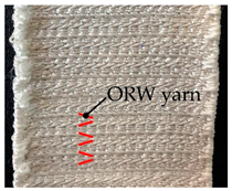 | 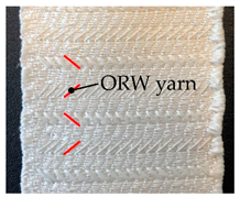 |
| Picture back | 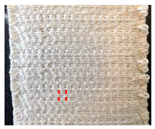 | 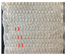 |
| GW1 | GW2 | GW3 | ||
|---|---|---|---|---|
| Weave | k1 | layer-to-layer satin | angle-through-thickness | layer-to-layer satin |
| k2 | layer-to-layer plain | angle-through-thickness | layer-to-layer plain | |
| k3 | angle-through-thickness | angle-through-thickness | angle-through-thickness | |
| ORW off-set warp/weft | k1 | - | 4/2 | 4/2 |
| k2 | - | 4/6 | 4/6 | |
| k3 | - | 4/12 | 4/12 | |
| Width (mm) | k1 | 24 | 30 | 24 |
| k2 | 24–30 | 30 | 24–30 | |
| k3 | 30 | 30 | 30 | |
| Picture of fabrics | 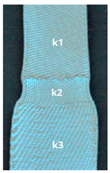 | 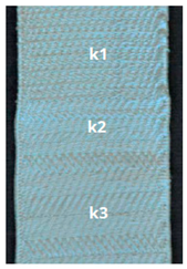 |  |
Publisher’s Note: MDPI stays neutral with regard to jurisdictional claims in published maps and institutional affiliations. |
© 2022 by the authors. Licensee MDPI, Basel, Switzerland. This article is an open access article distributed under the terms and conditions of the Creative Commons Attribution (CC BY) license (https://creativecommons.org/licenses/by/4.0/).
Share and Cite
Lang, T.G.; Nuß, D.; Gereke, T.; Hoffmann, G.; Wöltje, M.; Aibibu, D.; Cherif, C. Simulation-Based Development of Gradient Woven Fabrics for Biomimetic Implants to Restore Tendons and Ligaments. Textiles 2022, 2, 336-348. https://doi.org/10.3390/textiles2020019
Lang TG, Nuß D, Gereke T, Hoffmann G, Wöltje M, Aibibu D, Cherif C. Simulation-Based Development of Gradient Woven Fabrics for Biomimetic Implants to Restore Tendons and Ligaments. Textiles. 2022; 2(2):336-348. https://doi.org/10.3390/textiles2020019
Chicago/Turabian StyleLang, Tobias Georg, Dominik Nuß, Thomas Gereke, Gerald Hoffmann, Michael Wöltje, Dilbar Aibibu, and Chokri Cherif. 2022. "Simulation-Based Development of Gradient Woven Fabrics for Biomimetic Implants to Restore Tendons and Ligaments" Textiles 2, no. 2: 336-348. https://doi.org/10.3390/textiles2020019