Review

Hybrid Electric Vehicles: A Review of Existing Configurations and Thermodynamic Cycles

by
Rogelio León
,
Christian Montaleza
,
José Luis Maldonado
,
Marcos Tostado-Véliz
* and
Francisco Jurado
Department of Electrical Engineering, University of Jaén, EPS Linares, 23700 Jaén, Spain
*
Author to whom correspondence should be addressed.
Thermo 2021, 1(2), 134-150; https://doi.org/10.3390/thermo1020010
Submission received: 10 June 2021 / Revised: 15 July 2021 / Accepted: 21 July 2021 / Published: 22 July 2021

Abstract

:
The mobility industry has experienced a fast evolution towards electric-based transport in recent years. Recently, hybrid electric vehicles, which combine electric and conventional combustion systems, have become the most popular alternative by far. This is due to longer autonomy and more extended refueling networks in comparison with the recharging points system, which is still quite limited in some countries. This paper aims to conduct a literature review on thermodynamic models of heat engines used in hybrid electric vehicles and their respective configurations for series, parallel and mixed powertrain. It will discuss the most important models of thermal energy in combustion engines such as the Otto, Atkinson and Miller cycles which are widely used in commercial hybrid electric vehicle models. In short, this work aims at serving as an illustrative but descriptive document, which may be valuable for multiple research and academic purposes.

1. Introduction

Nowadays, low pollutant mobility throughout the world is being substantially developed and promoted, especially focusing on the automotive segment [1,2]. In this regard, the transport sector represents one of the main sources of air pollution [3], especially by contributing carbon monoxide, unsmoked hydrocarbons and nitrogen oxides ( N O x ) [4,5]. Because of the increasing importance given to pollution concerns, many efforts have been conducted in recent years to develop different techniques and approaches to minimize gas emissions caused by the mobility sector [6,7]. Thereby, the automotive industry is experiencing a deep transformation towards electric-based mobility [8,9]. This trend is provoking leading brands to be oriented to this new sector, by developing a plethora of novel vehicle models [10]. In this context, the launching of the Toyota Prius in December 1997 [11] was a first milestone that was followed in 1999 with the Honda Insight, a semi-hybrid with manual change or CVT of reduced size and weight, with a low fuel consumption and optimized aerodynamics [11,12]. At the same time, environmental anti-pollution laws are evolving to address the incoming environmental issues in order to safeguard ecosystems and people’s health [13]. Such is the case of the Euro standards, which are regulating key aspects such as emission bounds since 1988 [14]. Consequently, unlike the Japanese and American automotive markets which have objectives of manufacturing gasoline hybrid vehicles, hybrid solutions with diesel engines have been profusely studied in the European market by leading brands such as Citroën, Opel and Peugeot [12].
According to the Society of Automotive Engineers, a hybrid vehicle can be defined as that vehicle with two or more energy storage systems which must provide power to the propellant system either together or independently [15]. Similarly, the heavy duty hybrid vehicles group indicates that a hybrid vehicle must have at least two energy storage systems and energy converters. In practice, a hybrid electric vehicle (HEV) combines the great autonomy of conventional vehicles with spark ignition engines, compression ignition engines, fuel cells and solar panels with the speed, performance and environmental advantages of electric vehicles, obtaining an automobile with lower fossil fuel consumption and lower pollutant emissions to the atmosphere [16,17,18].
In general, pure electric vehicles have limited autonomy [19] (see Table 1 and Table 2), due to the low energy density of batteries [20] (see Table 3) compared with conventional liquid fuels for internal combustion engine (ICE) vehicles. The autonomy depends on the capacity of the batteries and the type of driving, but currently, with the advances of automotive technology, autonomies from 800 to 1000 km can be achieved [21,22], while the zero emissions autonomy (pure electric) ranges from 60 to 75 km. Most of commercial vehicles are plug-in (see Table 2), because their larger battery capacity and simpler recharging process compared with conventional hybrids [23,24]. On-board electric storage is normally composed by Li-ion batteries with a capacity 13–18 kWh (see Table 2). On the other hand, electric vehicles often have long recharging times. Nevertheless, fast and ultra-fast recharging technologies are emerged which enable recharging times about <30 min [25]. Nonetheless, this kind of infrastructures is still limited. In addition, many countries do not yet dispose of a sufficiently large network of recharging stations [17,18]. These limitations have supposed a formidable barrier to the widespread usage of pure electric vehicles. However, this trend is expected to be changed in a near future [26]. In this context, HEVs suppose a formidable alternative to pure electric vehicles. As commented, this development will be motivated by the implantation of more restrictive normative. For example, additional taxes on fuel consumption are being imposed in numerous European countries such as Spain [27]. In addition, there exists a continuous evolution on batteries technologies. For each generation, new technologies are developed for large-scale electric storage [28,29,30,31]. This research effort will have a direct impact on the large implantation of electric vehicles. As an example, one critical aspect in the automotive sector is the total weight of the storage system. This feature is strongly determined by the energy density of a battery technology, which is defined as the total weight (in kg) necessary to store 1 Wh. Figure 1 shows the evolution of this characteristic in recent years and the expected trend over a 20-year horizon for different technologies. As seen, emerging technologies such as Li-ion batteries are expected to offer very attractive characteristics for the automotive sector [20,32,33]. Other promising research areas are focused on designing states or specific power trains configurations for HEVs [34,35,36,37].
Besides the electrical part of an HEV, the conventional combustion layout is still present in current HEV models. The combustion components are expected to have a vital importance in future HEVs, helping to overcome the limitations of purely electric vehicles. In this sense, the combustion system is still necessary for extending the autonomy offered by the electric counterpart. In addition, electricity cost in many countries is still quite high and few competitive with traditional fuel prices. In this context, vehicle manufacturers and researchers have developed many configurations for coupling both systems. The various configurations with the application of a heat engine and an electric traction in an HEV seek significant improvements in autonomy, as the heat engine has the mission of recharging the batteries in a standard configuration and provides the propulsion force in conditions of constant running and overtaking. In this context, this work provides a review of the most typical configurations applied in industrial HEVs. In a second stage, the state of art of the thermodynamic models considered in such applications are reviewed. This way, this paper aims at providing an overall review of the current technological status of HEVs, with emphasis on the vehicle layout and mathematical models.
In the rest of this paper, Section 2 reviews the most typical configurations currently contemplated in HEVs. Section 3 develops the thermodynamic models of thermal cycles that are usually exploited for heat engines in HEVs. This paper is concluded with Section 4.

2. Most Typical Configurations for HEVs

In general, a powertrain system for a vehicle in general requires to meet a series of characteristics [17,18]:
  • High performance.
  • Low pollutant emissions from fossil fuels.
  • Enough energy storage on board to cover adequate autonomy.
  • Sufficient power generation to supply the various requirements in the driving and behavior of a vehicle.
The powertrain is defined as the junction of an energy source and the energy converter or also referred to as a power source. For example, gasoline and ICE, hydrogen-fuel cells and an electric motor, batteries and electric motor, etc. Figure 2 schematically shows the overall energy flows in a hybrid powertrain. In this case, there is the possibility of operating two powertrains according to load requirements. In the case of the vehicle with gasoline hybridization comprising ICE, battery system and electric motor, the path 1 indicated in Figure 2 is met. Through this energy path, the propulsion mode with ICE is only applied when the batteries are almost discharged and the ICE is not able to charge them, or also when the batteries have been fully charged and the ICE is able to supply the power demand of the vehicle. In contrast, the path 2 corresponds to the purely electric mode, in which the ICE is switched off, for example, at low speed or in zero pollutant emission zones [38]. The path 2 can be conducted in reverse mode when the batteries are charged from the ICE.
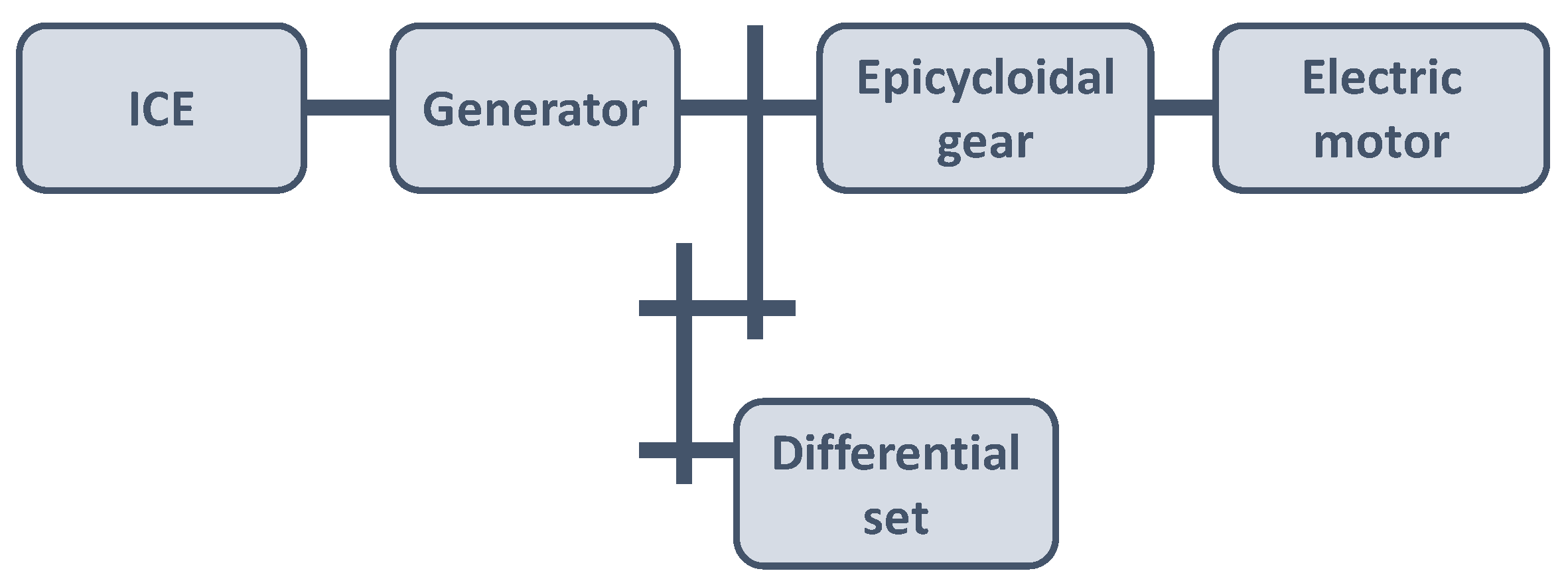
The transmission of an HEV lacks a conventional gearbox. In contrast, the central part in the transmission of such vehicles is the epicycloidal gear, also called planetary, from where the movement to the intermediate sprockets is transferred. The movement towards the differential assembly is through the intermediate sprockets while the backward movement is achieved by reversing the direction of the electric motor. For the sake of clarity, Figure 3 schematically illustrates a typical transmission for a hybrid vehicle.
Throughout this section, the most typical configurations with applications on HEVs are reviewed. In the literature, the different configurations in HEVs are broadly classified either on the basis of the hybridization level or according to its architecture [39,40].

2.1. Classification by Vehicle Hybridization Level

In essence, the hybridization concept refers to HEVs and mentions the level at which a vehicle could be considered as purely electric. Roughly speaking, the hybridization level determines the importance of the electric and combustion systems of an HEV. Thereby, the higher level of hybridization, the more important the electric system is. The hybridization of an HEV could be conceived from two different point of views [41]:
  • Hybridization of the propulsion system: this classification comprises those vehicles that have at the same time an electric traction system and another based on a heat engine (usually combustion or compression engines). Therefore, both systems have the ability, either independently or in combination, to propel the automobile. Propulsion system hybridization vehicles are composed of a heat and electric motor, but the latter is only used for starting and keeping the vehicle at low speeds over short distances.
  • Hybridization of the power supply system: in this case, the vehicles have more than one type of energy system, which could be either production or storage, being at least one of them purely electric. Intuitively, this configuration must count with at least an electric motor. The hybridization system with power supply combines an electrical system and a fuel that serves to increase the autonomy, but the tractor system will be electric, being the function of the heat engine to recharge the batteries when they are running out. This model is also valid for fuel-cell electric vehicles, in which the electric energy is produced through fuel cells that convert hydrogen to electrical energy [42].
According to [43], the above classification can be further subdivided into four levels. In that sense, the electric part in a hybrid vehicle is increased as it reaches a significant percentage of hybridization. That is, with the increase in the rate of hybridization, the environmental impact continues to decrease, but the level of complexity (power control, coupling, energy diversification) of the vehicle system continues to increase until there is no longer the need of a heat engine. This classification approach is described in subsequent sections.

2.1.1. Micro-Hybrid

The vehicles in this classification encompass the alternator and the start button in the same set. A small electric motor is other key feature of this kind of vehicles. In this sense, the engine only serves to charge the battery system as much as possible during braking phases, besides providing the so-called ‘Stop and Start’ service, which is devoted on restoring the heat engine before starting the running. In this sense, any automobile that provides such kind of capability could be encompassed into this category. One highlight of the ‘Stop and Start’ service is the moment during which the engine is put on below 6 km/h, and starts automatically with the help of the electric motor when it needs to accelerate again. Finally, it is worth remarking that vehicles within this category usually present a petrol economy between 5% and 8%.

2.1.2. Mild-Hybrid

In the second category, the mild-hybrid vehicles have a more powerful electric motor and are usually equipped with a higher capacity battery system. This configuration allows the electric system supports the heat engine even during acceleration. However, the electric counterpart is still only able to partially fulfill the function of ICE, because it lacks the sufficiently capacity for propelling the vehicle by itself. In this kind of HEV, the electric system is also used to start the propulsion of the vehicle and initialize the whole traction system. This type of hybridization system allows to recover the kinetic energy of the vehicle through the braking phase with reversible electrical components, in the same way the gasoline economy is favorable because it typically ranges from 20% to 25%.

2.1.3. Full-Hybrid

In this category, the vehicles typically encompass a heat engine (MEP-MEC) and an electric motor both connected to the transmission. Additionally, this scheme incorporates a generator and a high capacity battery. The full hybrid vehicles usually can operate under pure-electric mode up to 30 or 40 km/h, beyond that, the electric system needs to be supported by the heat engine. During acceleration, the electric motor supports the thermal system, whereas in braking and retention the kinetic energy is transformed into electricity and stored in batteries. The electric motor is also useful during starting processes, which makes this configuration very suitable for long trips with frequent start-stop transitions. Both systems are mechanically connected with the wheels, allowing to circulate in electric mode, being the most efficient solution allowing to reduce the gasoline consumption by ~45%. The Toyota Prius supposes a notorious example of this kind of hybridization level. This vehicle uses a permanent electric motor coupled to the transmission and a petrol engine that gives movement to a generator, also incorporating a 200 V battery located at the rear. The size of the heat engine can be reduced, applying the concept of downsizing and large capacity battery. Figure 4 shows a typical architecture of a full hybrid vehicle.

2.1.4. Plug-in-Hybrid

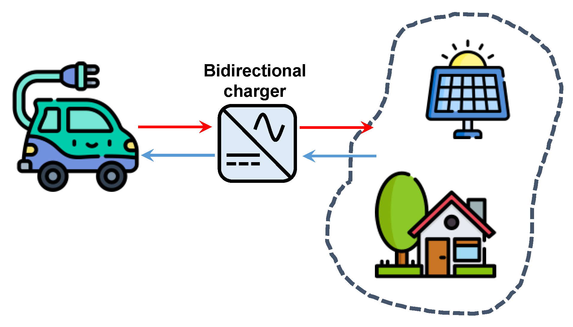
The vehicles within this category present an architecture very similar to the full-hybrid level. However, the plug-in-hybrid has the capability of being connected to an upscale electric grid. This way, the battery system can be recharged from the traction system during breaking stages or directly from the electric system. One interesting feature of this kind of vehicle is the possibility of exploiting the on-board storage system for grid supporting tasks. For example, the vehicle batteries could be exploited as storage facilities in smart homes through bidirectional chargers, thus supporting the labor of onsite renewable generators on pursuing a more efficient energy management in dwellings [43]. This principle is called vehicle-to-home and is illustrated in Figure 5.

2.2. Classification by Architecture

In the literature (e.g., see [40]), the HEVs are often classified attending to their architecture. This classification attends to the on-board system layout, components and interconnection and enabled energy paths among them. Subsequent sections describe the different categories within this classification approach.

2.2.1. Series Configuration

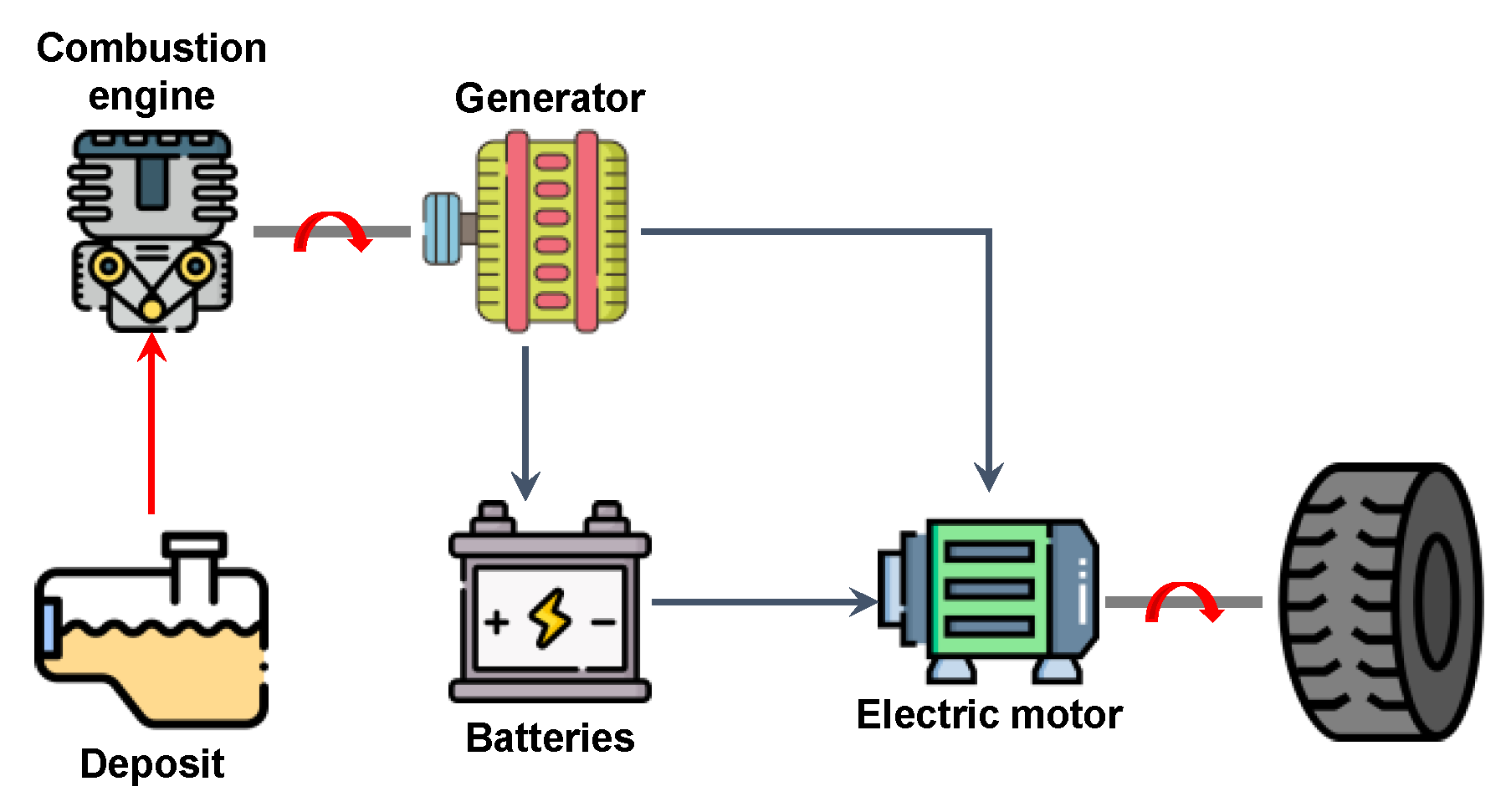
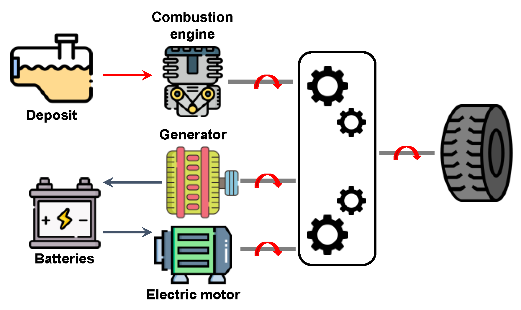
These kinds of vehicles are also called vehicles of extended autonomy. In this case, the vehicle is driven entirely by the electric motor, which is moved by a heat engine with fuel supply. Figure 6 depicts a schematic diagram of this architecture. The mechanical output of the ICE is first converted into electricity by a generator; then, this energy could be destined to charge the batteries or propel the wheels through the electric motor, which also allows to capture the energy during braking. Thereby, the ICE is mechanically decoupled to the transmission system. This configuration allows to operate the ICE efficiently, since its torque and speed are independent of the mechanical demand of the vehicle. Hence, the ICE can be operated at any point of its characteristics. This way, the vehicle generally works at those operating points by which consumption and emissions are minimal. By this configuration, the battery system acts an accumulator facility that can store the excess of energy thus allowing to disconnect the ICE momentarily. This principle is normally handled by energy management programs, which continuously control the state of charge of the batteries on pursuing a fuel consumption reduction [44,45].

2.2.2. Parallel Configuration

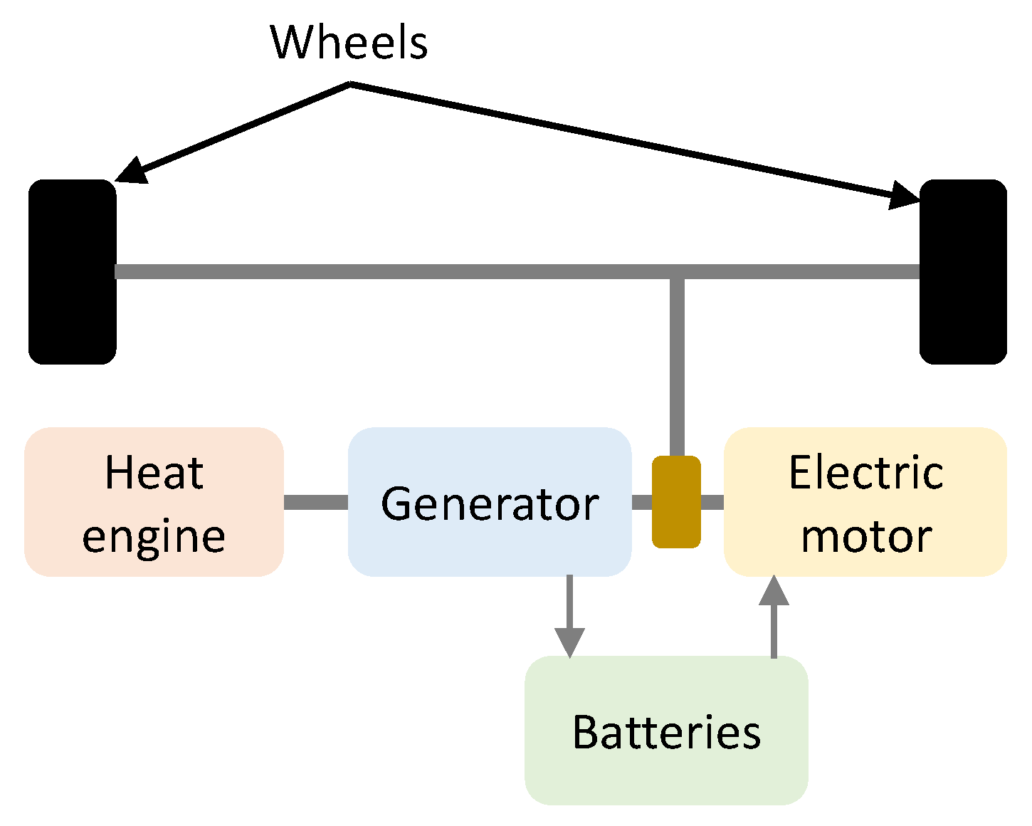
By this configuration, both the heat and electric engines can propel the transmission systems. An electric hybrid vehicle with the parallel configuration has the ICE and electric motor coupled to the final drive axle of the wheels via clutches. Moreover, this configuration allows the ICE and electric motor to supply power to drive the wheels in combined or isolated modes. This way, both systems work in parallel. Figure 7 shows the schematic diagram of the parallel configuration for HEVs. This configuration supposes a remarkable simplification of the series architecture as the electric generator is no longer necessary [44]. In this sense, the electric motor could work in reverse mode, converting the kinetic energy of the transmission system to electricity which is stored in batteries. Generally, ICE size can be reduced reduce with respect to (w.r.t.) the series configuration [45].

2.2.3. Mixed Configuration

In essence, this configuration combines both previous architectures on a whole. This way, the vehicle could be propelled in this case through the ICE, the electric motor or both systems at once [45]. The heat engine is directly connected to the transmission system and is mechanically coupled to the electric system through a differential set, which mechanically couples both electric and heat systems. The electric system is composed by a motor and a generator, which allows to convert the excess of energy produced by the ICE during braking into electricity to be stored in batteries. By far, this configuration is more complex than the others, but allows to gather all the advantages obtained with series and parallel configurations. Figure 8 presents a diagram of the mixed configuration for HEVs.

2.2.4. Summary of Architectures for HEVs

For the sake of summarizing, Table 4 provides a summary of the main advantages of disadvantages of the different architectures for HEVs described in the previous subsections.

3. Thermodynamic Models for HEVs

In this section, the most common thermodynamic processes in HEVs and the mathematical formulations usually considered for modeling them are reviewed. In this sense, thermodynamic processes in an HEV are frequently modeled by thermal cycles, thus allowing a simplification of their conceptualization making their analysis and optimization significantly simpler [46,47,48,49]. In addition, the analysis of the thermodynamic cycles will allow an understanding of the fundamental trends for the design of the engines. Subsequent sections describe the most usual thermodynamic cycles in HEVs, i.e., Otto, Atkinson and Miller cycles.

3.1. Nomenclature

The nomenclature used through this section is listed below for simplicity.
  • Q  Heat
  • W  Work
  • T  Temperature
  • S  Entropy
  • p  Pressure
  • V  Volume
  • η  Thermal efficiency
  • U  Energy
  • m ˙  Mass flow
The subscripts denote the different stages of the thermodynamic cycles, as they are labelled in the corresponding figures.

3.2. Otto Cycle

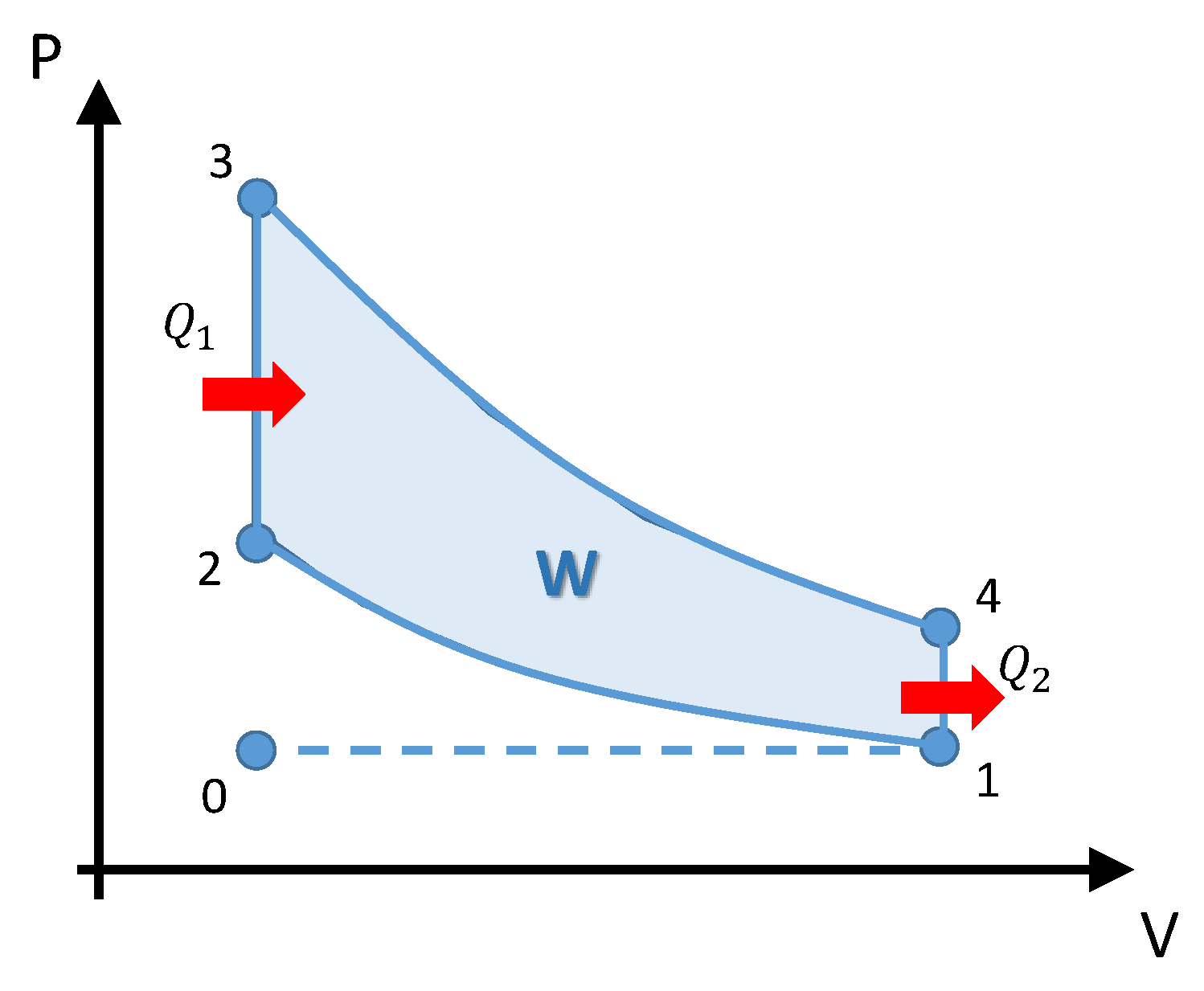
This cycle is associated with the ignition process that happens in the heat engine. In the literature, this cycle is also called Spark ignition. Figure 9 shows the p / V scheme of the Otto cycle whose main steps are:
  • Adiabatic compression (1–2): compression of the working fluid, the piston has to perform the work W 1 .
  • Contribution of heat at constant volume (2–3): instantaneous introduction of the heat Q 1 is provided.
  • Adiabatic expansion (3–4): expansion, which is corresponding to the W 2 work, performed by the working fluid.
  • Extraction of heat at constant volume (4–5): instantaneous extraction of Q 2 heat.
In the engines of four strokes (4T), the extraction of heat occurs in the exhaust phase, from the opening of the exhaust valve (4–1–0). In addition, the mixture of the air–fuel fluid is introduced into the intake stroke (0–1). This process is graphically represented in the horizontal dashed line of the p / V diagram of Figure 9. Theoretically the processes (1–0 and 0–1) between them are cancelled out, in such a way that a loss or gain of zero heat is generated, so that the p / V diagram of the ideal Otto cycle only considers the closed cycle. Similarly, the work in this phase is zero, W 2 3 = 0 the heat supply is performed at constant Q 1 volume [41,50].
From the p / V diagram of the Otto cycle in Figure 9 one can establish the following relationships:
V 2 = V 3 ,   V 4 = V 1
While the compression ( C R ) and pressure ( P R ) ratios for this cycle are given by [46]:
C R = V 1 V 3
P R = p 3 p 1
The thermal efficiency of the Otto cycle can be established as [51]:
η O t t o = 1 T 1 T 2
The first law can be applied to the adiabatic process (1–2), obtaining [46]:
T 1 T 2 = ( V 1 V 2 ) 1 K
where K is the specific heat ratio defined as:
K = c p c v
where c v and c p are the specific heat of the gas at constant volume and pressure, respectively. This way, the Equation (4) can be rewritten:
η O t t o = 1 C R 1 K
By the mathematical model above, the performance of an Otto cycle only depends on the values of K and C R , and therefore it is not affected by the amount of heat provided or the degree of explosion [50]. The influence of such parameters on the thermal efficiency of the Otto cycle is shown in Figure 10 [48,49]. For a given value of K , thermal efficiency notably increases with increasing C R at low values of the compression ratio. This trend changes for higher values of the volumetric compression ratio (approximately C R = 10 ). Beyond this threshold, thermal efficiency curves flatten out, lessening the benefits of working with high pressures.
The mathematical model described above for the Otto cycle responds to ideal conditions. In practice, performing of heat engines may be far away to these ideal conditions mainly due to the following reasons [52]:
  • Heat loss through the walls, caused by the need to have a cooling system for the ignition engines organs.
  • Need to anticipate ignition with respect to death point, because combustion is not instantaneous and a certain time is needed.
  • Exhaust opening advance, due to the inertia of the valves and gas masses.
  • Loss of pumping work during the exhaust and intake stroke.

3.3. Atkinson Cycle

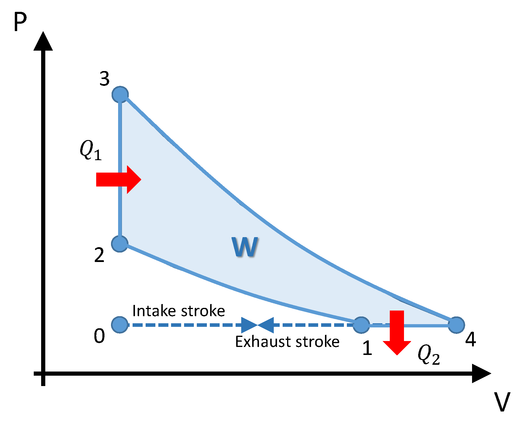
The vast majority of hybrid electric vehicles use the Atkinson cycle for internal combustion engines because its higher efficiency [51]. This cycle is characterized by having a longer expansion stroke than the compression one, thus largely managing the energy available in the injected fuel [53]. In this way, the mixture has more time to expand and produces within the combustion chamber a greater amount of work [54]. The Atkinson cycle is relatively ideal for a hybrid vehicle since the internal combustion engine with this cycle has greater efficiency in thermal energy, but at the cost of low power [55]. In this regard, an electric motor is generally needed to complement the heat engine [56]. Figure 11 depicts the p / V diagram of the Atkinson cycle, which comprises an adiabatic compression (1–2), addition of isochoric heat (2–3), an adiabatic expansion (3–4) and finally isobaric heat extraction.
From the p / V showed in Figure 11, the following relations are deduced:
V 2 = V 3 ,   p 1 = p 4
Let us define the compression, temperature ( T R ) and pressure ratios for this cycle as follows [46]:
C R = V 4 V 3
T R = T 3 T 1
P R = p 3 p 4
The amount of heat supplied and rejected can be deduced as follows:
Q 1 = m ˙ c v ( T 3 T 2 )
Q 2 = m ˙ c p ( T 4 T 1 )
Dividing (13) by (12) and simplifying one obtains:
Q 2 Q 1 = K ( T 4 / T 1 ) 1 ( T 3 / T 1 ) ( T 2 / T 1 )
Now, observing the adiabatic processes 1–2 and 3–4, one has:
T 2 T 1 = ( V 2 V 1 ) 1 K = ( V 3 V 4 T 4 T 1 ) 1 K = ( C R 1 T 4 T 1 ) 1 K
T 4 T 3 = ( V 4 V 3 ) 1 K = C R 1 K
The Equation (16) could be used to determine the useful ratio T 4 T 1 , as follows:
T 4 T 1 = T R · C R 1 K
Next, replacing (17) into (15) one obtains:
T 2 T 1 = ( T R · C R K ) 1 K
The expression for the thermal efficiency of the Atkinson cycle can now be obtained by substituting (17) and (18) into (14), which yields:
η A t k i n s o n = 1 K T R · C R 1 K 1 T R ( T R · C R K ) 1 K
From (9) and (11) the following relationship can be established in the Atkinson cycle:
C R = P R 1 K
Equation (20) allows to derive an alternative expression for the thermal efficiency as a function of the pressure and temperature ratios, as follows:
η A t k i n s o n = 1 K T R · P R 1 K K 1 T R ( T R P R ) 1 K

3.4. Miller Cycle

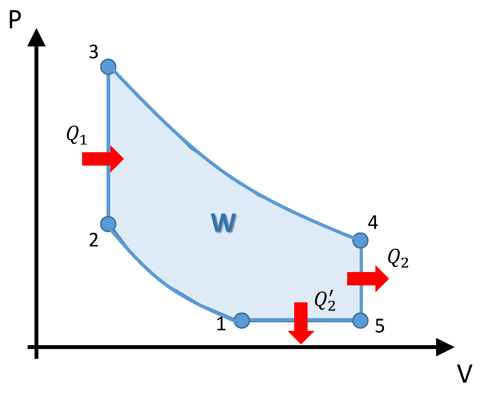
The Miller cycle is used in those hybrid vehicles in which the lack of torque from the engine is compensated by the addition of the electric motor. In the Miller cycle a larger cylinder than usual is usually used. The compression stroke is shortened in conjunction with the expansion stroke, where, as the piston moves upwards in the compression stroke the load is pushed out of the normally closed valve [57]. Delaying the closing time of the intake valves causes the temperature of the mixture to be reduced as well as the load mixture fraction. Consequently, the indicated effective average pressure and net cyclic work is reduced [58]. To solve this issue, a variable valve timing mechanism could be used to increase the efficiency of the Miller cycle [59,60]. Figure 12 plots the P / V diagram of the Miller cycle which comprises an adiabatic compression (1–2), addition of isochoric heat (2–3), an adiabatic expansion (3–4), elimination of isochoric heat (4–5) and elimination of isobaric heat (5–1).
From the Figure 12 one can directly deduces:
V 2 = V 3 ,   V 4 = V 5 ,   p 5 = p 1
Whereas the compression, temperature and pressure ratios are respectively defined for this cycle as follows [46]:
C R = V 5 V 3
T R = T 3 T 1
P R = p 3 p 5
The thermal efficiency of the Miller cycle is determined by the relationship between the total and supplied heats, as follows [46]:
η M i l l e r = 1 Q 2 + Q 2 Q 1 = 1 c v ( T 4 T 5 ) + c p ( T 5 T 1 ) c v ( T 3 T 2 )
The Equation (26) can be rewritten as a function of the specific heat ratio straightforward as:
η M i l l e r = 1 ( T 4 / T 1 ) + ( K 1 ) ( T 5 / T 1 ) K T R ( T 2 / T 1 )
By using the relations of the adiabatic process, the following relations must hold for the Miller cycle:
T 4 T 3 = ( V 4 V 3 ) 1 K = ( V 5 V 3 ) 1 k = C R 1 K
p 4 = p 3 ( V 4 V 3 ) K = p 3 C R K
The ratio T 4 T 1 can be deduced from Equation (28):
T 4 T 1 = T R · C R 1 K
For the isochoric process 4–5, the following relation holds:
T 5 = T 4 ( p 5 p 4 )
By using the relations (30) and (31) one can deduce:
T 5 T 1 = T 4 T 1 p 5 p 4 = ( T R · C R 1 K ) p 5 p 3 C R K = T R C R P R
For the isobaric process 5–1 the following relation holds:
V 1 = V 5 ( T 1 T 5 )
Combining (33) and the relationship valid for 1–2, the following expression can be easily derived:
T 2 T 1 = ( V 2 V 1 ) 1 K = ( V 3 T 5 V 5 T 1 ) 1 K = ( 1 C R T R C R P R ) 1 K = ( T R P R ) 1 K
Finally, one can insert the result (34) into (27) to obtain:
η M i l l e r = 1 P R · C R 1 K + ( K 1 ) C R K ( P R T R ) P R ( P R T R ) K

3.5. Finite Time Thermodynamics

Finally, this paper briefly introduces the Finite Time Thermodynamics (FTT) concept. FTT is a branch of thermodynamics theory, which aims at modeling those processes which take place during a finite time rate [61,62]. In contrast to conventional theory, FTT is conceived from a macroscopic point of view with heat conductances, friction coefficients, overall reaction rates, etc [63]. The very first steps of FTT took place in the mid-1970s, when Curzon and Ahlborn [64] derived the efficiency term of a Carnot engine considering finite heat transfer between the working fluid and heat reservoir. This idea can be extended to any other endoreversible system (i.e., internally reversible) such as Otto [65], Atkinson [66] and Miller cycles [67]. Nowadays, FTT has a crucial importance for studying optimum performances and configurations of internal combustion engines. Recent progresses are mainly devoted to further analyzing the optimum performances of air standard cycles, determining the optimal path of internal combustion cycles, assessing the limits of the cycles, and development of advanced simulation frameworks [62].
An illustrative example of the importance of FTT, is the analysis of the specific heat of working fluid. Traditionally, this parameter was considered constant. However, as pointed out in [62], this assumption does not reflect the reality. For practical, cycles, properties of working fluids change due to combustion reactions. These variations of the base parameters may introduce significant inaccuracies in the study of thermodynamic cycles. To solve this issue, the reference [68] introduced the concept of variable specific heat. In its simplest model, the specific heat varies linearly with the temperature, as follows [69]:
c p = α p + K · T
c v = α v + K · T
where α ’s are constant parameters.
Another important aspect in which traditional theories are not applicable is the consideration of heat transfer losses, for which the cycle maximum temperature should not be considered fixed [70]. On the other hand, other studies consider the quantum characteristics of the working fluid [71], in contrast to classical techniques which are based on phenomenological law and equilibrium statistical mechanics.

4. Conclusions

This paper has presented an illustrative but descriptive review of the most typical configurations and architectures for hybrid electric vehicles. Accordingly, the different configurations have been classified attending to different criteria contemplated in the literature. The main advantages and disadvantages of each architecture have been identified and highlighted with the aim of serving as a valuable contribution to related research and academic purposes. On the other hand, the usual thermodynamic cycles that are typically exploited in HEVs have been developed and reviewed. Thus, Otto, Atkinson and Miller cycles have been mathematically elaborated and descriptively illustrated.
The review presented in this paper has been performed as illustratively as possible, so as to be of interest for the wider public. Additionally, a variety of key references have been provided with the aim of serving as a bibliographic benchmark for the ease of further expanding the scope of this paper.

Author Contributions

Conceptualization, R.L., C.M. and J.L.M.; methodology, R.L., C.M. and J.L.M.; software, R.L., C.M. and J.L.M.; validation, R.L., C.M. and J.L.M.; formal analysis, M.T.-V.; investigation, R.L., C.M., J.L.M. and M.T.-V.; resources, M.T.-V. and F.J.; data curation, M.T.-V. and F.J.; writing—original draft preparation, R.L., C.M. and J.L.M.; writing—review and editing, M.T.-V. and F.J.; visualization, M.T.-V.; supervision, M.T.-V. and F.J.; project administration, M.T.-V. and F.J.; funding acquisition, F.J. All authors have read and agreed to the published version of the manuscript.

Funding

This research received no external funding.

Institutional Review Board Statement

Not applicable.

Informed Consent Statement

Not applicable.

Data Availability Statement

Not applicable.

Acknowledgments

The icons used in this article were developed by Freepik, Flat icons and dDara from www.flaticon.com (accessed on 21 July 2021).

Conflicts of Interest

The authors declare no conflict of interest.

References

  1. Choma, E.F.; Evans, J.S.; Hammitt, J.K.; Gómez-Ibáñez, J.A.; Spengler, J.D. Assessing the health impacts of electric vehicles through air pollution in the United States. Environ. Int. 2020, 144, 106015. [Google Scholar] [CrossRef]
  2. Cárcel-Carrasco, J.; Pascual-Guillamón, M.; Salas-Vicente, F. Analysis on the Effect of the Mobility of Combustion Vehicles in the Environment of Cities and the Improvement in Air Pollution in Europe: A Vision for the Awareness of Citizens and Policy Makers. Land 2021, 10, 184. [Google Scholar] [CrossRef]
  3. Yang, X.; Lin, W.Q.; Gong, R.X.; Zhu, M.Z.; Springer, C. Transport decarbonization in big cities: An integrated environmental co-benefit analysis of vehicles purchases quota-limit and new energy vehicles promotion policy in Beijing. Sustain. Cities Soc. 2021, 71, 102976. [Google Scholar] [CrossRef]
  4. Xie, Y.; Wu, D.; Zhu, S. Can new energy vehicles subsidy curb the urban air pollution? Empirical evidence from pilot cities in China. Sci. Total Environ. 2021, 754, 142232. [Google Scholar] [CrossRef]
  5. Pini, F.; Piras, G.; Garcia, D.A.; Di Girolamo, P. Impact of the different vehicle fleets on PM10 pollution: Comparison between the ten most populous Italian metropolitan cities for the year 2018. Sci. Total Environ. 2021, 773, 145524. [Google Scholar] [CrossRef] [PubMed]
  6. Zhao, J.; Xi, X.; Na, Q.; Wang, S.; Kadry, S.N.; Kumar, P.M. The technological innovation of hybrid and plug-in electric vehicles for environment carbon pollution control. Environ. Impact Assess. Rev. 2021, 86, 106506. [Google Scholar] [CrossRef]
  7. Breuer, J.L.; Samsun, R.C.; Stolten, D.; Peters, R. How to reduce the greenhouse gas emissions and air pollution caused by light and heavy duty vehicles with battery-electric, fuel cell-electric and catenary trucks. Environ. Int. 2021, 152, 106474. [Google Scholar] [CrossRef] [PubMed]
  8. Alla, S.A.; Bianco, V.; Tagliafico, L.A.; Scarpa, F. Pathways to electric mobility integration in the Italian automotive sector. Energy 2021, 221, 119882. [Google Scholar] [CrossRef]
  9. Ajanovic, A.; Haas, R.; Schrodl, M. On the Historical Development and Future Prospects of Various Types of Electric Mobility. Energies 2021, 14, 1070. [Google Scholar] [CrossRef]
  10. Torreglosa, J.P.; Garcia-Trivino, P.; Vera, D.; Lopez-Garcia, D.A. Analyzing the Improvements of Energy Management Systems for Hybrid Electric Vehicles Using a Systematic Literature Review: How Far Are These Controls from Rule-Based Controls Used in Commercial Vehicles? Appl. Sci. 2020, 10, 8744. [Google Scholar] [CrossRef]
  11. Clifford, J. History of the Toyota Prius. Toyota UK Mag. 2015. Available online: https://mag.toyota.co.uk/history-toyota-prius/ (accessed on 2 June 2021).
  12. Kim, N.; Rousseau, A. Thermal impact on the control and the efficiency of the 2010 Toyota Prius hybrid electric vehicle. Proc. Inst. Mech. Eng. Part D J. Automob. Eng. 2016, 230, 82–92. [Google Scholar] [CrossRef]
  13. Jin, Y.N.; Andersson, H.; Zhang, S.Q. Air Pollution Control Policies in China: A Retrospective and Prospects. Int. J. Environ. Res. Public Health 2016, 13, 1219. [Google Scholar] [CrossRef] [PubMed] [Green Version]
  14. Tostado-Véliz, M.; Bayat, M.; Ghadimi, A.A.; Jurado, F. Home Energy Management in off-grid Dwellings: Exploiting Flexibility of Thermostatically Controlled Appliances. J. Clean. Prod. 2021, 310, 127507. [Google Scholar] [CrossRef]
  15. Society of American Engineers. Hybrid Electric Vehicle (HEV) & Electric Vehicle (EV) Terminology; J1715_200802; Society of American Engineers: Warrendale, PA, USA, 2008. [Google Scholar]
  16. Hannan, M.A.; Azidin, F.A.; Mohamed, A. Hybrid electric vehicles and their challenges: A review. Renew. Sustain. Energy Rev. 2014, 29, 135–150. [Google Scholar] [CrossRef]
  17. Alegre, S.; Míguez, J.V.; Carpio, J. Modelling of electric and parallel-hybrid electric vehicle using Matlab/Simulink environment and planning of charging stations through a geographic information system and genetic algorithms. Renew. Sustain. Energy Rev. 2017, 74, 1020–1027. [Google Scholar] [CrossRef]
  18. Kumar, P.R.; Shankar, C.G.; Uthirasamy, R.; Vijayalakshmi, V.J. A Review of Electric Vehicle Technologies. In Proceedings of International Conference on Artificial Intelligence, Smart Grid and Smart City; Kumar, L.A., Jayashree, L.S., Manimegalai, R., Eds.; Springer: New York, NY, USA, 2019. [Google Scholar]
  19. U. S. Department of Energy. Fuel Economy Guide. 2021. Available online: https://www.fueleconomy.gov/feg/pdfs/guides/FEG2021.pdf (accessed on 15 July 2021).
  20. IDAE. Guía para la Promoción del Vehículo Eléctrico en las Ciudades; IDAE: Madrid, Spain, 2011. Available online: https://www.movilidad-idae.com/sites/default/files/2019-06/Gu%C3%ADaPromoci%C3%B3nVECiudades_2011.pdf (accessed on 2 June 2021).
  21. Adhikari, M.; Ghimire, L.P.; Kim, Y.; Aryal, P.; Khadka, S.B. Identification and Analysis of Barriers against Electric Vehicle Use. Sustainability 2021, 12, 4850. [Google Scholar] [CrossRef]
  22. Endesa, X. 7 Differences between an Electric Vehicle and a Plug-In Hybrid. Available online: https://www.endesax.com/en/resources/stories/cirve-iberian-fast-charging-corridors1 (accessed on 15 July 2021).
  23. Cao, J.F.; He, H.W.; Wei, D. Intelligent SOC-consumption allocation of commercial plug-in hybrid electric vehicles in variable scenario. Appl. Energy 2021, 281, 115942. [Google Scholar] [CrossRef]
  24. Hajipour, E.; Mohiti, M.; Farzin, N.; Vakilian, M. Optimal distribution transformer sizing in a harmonic involved load environment via dynamic programming technique. Energy 2017, 120, 92–105. [Google Scholar] [CrossRef]
  25. Zhao, Y.; He, X.; Yao, Y.; Huang, J.J. Plug-in electric vehicle charging management via a distributed neurodynamic algorithm. Appl. Soft Comput. 2019, 80, 557–566. [Google Scholar] [CrossRef]
  26. España 2050: Aumento de Impuestos a la Gasolina y al Diésel y una Tasa por el uso Del Vehículo. Heraldo updated 27 May 2021. Available online: https://www.heraldo.es/noticias/nacional/2021/05/20/gobierno-subira-impuestos-gasolina-diesel-creara-tasa-uso-medio-vehiculo-1493577.html (accessed on 2 June 2021).
  27. Arévalo, P.; Tostado-Véliz, M.; Jurado, F. A Novel Methodology for Comprehensive Planning of Battery Storage Systems. J. Energy Storage 2021, 37, 102456. [Google Scholar] [CrossRef]
  28. Hilgers, M.; Achenbach, W. Alternative Powertrains and Extensions to the Conventional Powertrain; Springer Vieweg: Wiesbaden, Germany, 2021; pp. 17–41. [Google Scholar]
  29. Harper, G.; Sommerville, R.; Kendrick, E.; Driscoll, L.; Slater, P.; Stolkin, R.; Walton, A.; Christensen, P.; Heidrich, O.; Lambert, S.; et al. Recycling lithium-ion batteries from electric vehicles. Nature 2019, 575, 75–86. [Google Scholar] [CrossRef] [Green Version]
  30. Zu, C.-X.; Li, H. Thermodynamic analysis on energy densities of batteries. Energy Environ. Sci. 2011, 4, 2614–2624. [Google Scholar] [CrossRef]
  31. Van Noorden, R. The rechargeable revolution: A better battery. Nature 2014, 507, 26–28. [Google Scholar] [CrossRef] [PubMed] [Green Version]
  32. Cano, Z.P.; Banham, D.; Ye, S.; Hitennach, A.; Lu, J.; Fowler, M.; Chen, Z. Batteries and fuel cells for emerging electric vehicle markets. Nat. Energy 2018, 3, 279–289. [Google Scholar] [CrossRef]
  33. Dimitrova, Z. Predictive and holistic energy distribution for hybrid electric vehicles. MATEC Web Conf. 2017, 133, 02002. [Google Scholar] [CrossRef] [Green Version]
  34. Dimitrova, Z. Performance and economic analysis of an organic Rankine Cycle for hybrid electric vehicles. IOP Conf. Ser. Mater. Sci. Eng. 2019, 664, 012009. [Google Scholar] [CrossRef]
  35. Capata, R.; Scuibba, E. Study, Development and Prototyping of a Novel Mild Hybrid Power Train for a City Car: Design of the Turbocharger. Appl. Sci. 2020, 11, 234. [Google Scholar] [CrossRef]
  36. Capata, R. Preliminary Analysis of a New Power Train Concept for a City Hybrid Vehicle. Designs 2021, 5, 19. [Google Scholar] [CrossRef]
  37. Mapelli, F.L.; Tarsitano, D. Energy control for Plug-In HEV with ultracapacitors lithium-ion batteries storage system for FIA Alternative Energy Cup Race. In Proceedings of the 2010 IEEE Vehicle Power and Propulsion Conference, Lille, France, 1–3 September 2010; pp. 1–6. [Google Scholar] [CrossRef]
  38. Center for Advanced Automotive Technology. HEV Levels. Available online: http://autocaat.org/Technologies/Hybrid_and_Battery_Electric_Vehicles/HEV_Levels/#:~:text=Vehicles%20%3E%20HEV%20Levels-,HEV%20Levels,the%20function%20of%20regenerative%20braking (accessed on 2 June 2021).
  39. Zhang, F.; Wang, L.; Coskun, S.; Pang, H.; Cui, Y.; Xi, J. Energy Management Strategies for Hybrid Electric Vehicles: Review, Classification, Comparison, and Outlook. Energies 2020, 13, 3352. [Google Scholar] [CrossRef]
  40. Ge, Y.; Chen, L.; Sun, F.; Wu, C. Thermodynamic simulation of performance of an Otto cycle with heat transfer and variable specific heats of working fluid. Int. J. Therm. Sci. 2005, 44, 506–511. [Google Scholar] [CrossRef]
  41. Tostado-Véliz, M.; Arévalo, P.; Jurado, F. A Comprehensive Electrical-Gas-Hydrogen Microgrid Model for Energy Management Applications. Energy Convers. Manag. 2021, 228, 113726. [Google Scholar] [CrossRef]
  42. Guzzella, L.; Sciarretta, A. Vehicle Propulsion Systems, 3rd ed.; Springer: Berlin/Heidelberg, Germany, 2012. [Google Scholar]
  43. Tostado-Véliz, M.; León-Japa, R.S.; Jurado, F. Optimal Electrification of Off-grid Smart Homes Considering Flexible Demand and Vehicle-to-Home Capabilities. Appl. Energy 2021, 298, 117184. [Google Scholar] [CrossRef]
  44. Onori, S.; Serrao, L.; Rizzoni, G. Hybrid Electric Vehicles: Energy Management Strategies; Springer: Berlin/Heidelberg, Germany, 2016. [Google Scholar]
  45. Miller, J.M. Propulsion Systems for Hybrid Vehicles; The Institution of Electrical Engineers: London, UK, 2004; Volume 45. [Google Scholar]
  46. Haseli, Y. Most efficient engine. In Entropy Analysis in Thermal Engineering Systems; Haseli, Y., Ed.; Academic Press: Cambridge, MA, USA, 2020. [Google Scholar] [CrossRef]
  47. Naber, J.D.; Johnson, J.E. Internal combustion engine cycles and concepts. In Alternative Fuels and Advanced Vehicle Technologies for Improved Environmental Performance; Folkson, R., Ed.; Woodhead Publising: Cambridge, MA, USA, 2014. [Google Scholar]
  48. Balmer, R.T. Vapor and Gas Power Cycles. In Modern Engineering Thermodynamics; Balmer, R.T., Ed.; Academic Press: Cambridge, MA, USA, 2011. [Google Scholar] [CrossRef]
  49. Dincer, I.; Demir, M.E. Gas Turbine Cycles. In Comprehensive Energy Systems; Dincer, I., Ed.; Elsevier: Oxford, UK, 2018. [Google Scholar]
  50. Gathadi, P.; Bhole, A. Electric Motors and Rotor Position Detection Techniques of Integrated Starter Alternator for HEV: A Review. In Proceedings of the 2018 International Conference on Current Trends towards Converging Technologies (ICCTCT), Coimbatore, India, 1–3 March 2018; pp. 1–6. [Google Scholar] [CrossRef]
  51. Chandra, M.; Dan, P.K.; Bhattacharjee, D.; Mandol, S.; Patra, P. Devising Product Design Architecture Strategies: Case of HEV Powertrain. In Research into Design for a Connected World; Chakrabarti, A., Ed.; Springer Nature: Singapore, 2019; Volume 134. [Google Scholar] [CrossRef]
  52. Park, H.G.; Kwon, Y.J.; Hwang, S.J.; Lee, H.D.; Kwon, T.S. A Study for the estimation of temperature and thermal life of traction motor for commercial HEV. In Proceedings of the 2012 IEEE Vehicle Power and Propulsion Conference, Seoul, Korea, 9–12 October 2012; pp. 160–163. [Google Scholar] [CrossRef]
  53. Zhou, X.; Qin, D.; Rotella, D.; Cammalleri, M. Hybrid Electric Vehicle Powertrain Design: Construction of Topologies and Initial Design Schemes. In Advances in Italian Mechanism Science; Carbone, G., Gasparetto, A., Eds.; Springer Nature: Cham, Switzerland, 2019; Volume 68, pp. 49–60. [Google Scholar] [CrossRef]
  54. Maggetto, G.; Van, J. Electric vehicles, hybrid electric vehicles and fuel cell electric vehicles: State of the art and perspectives. Ann. Chim. Sci. Mater. 2001, 26, 9–26. [Google Scholar] [CrossRef]
  55. Capata, R. Urban and Extra-Urban Hybrid Vehicles: A Technological Review. Energies 2018, 11, 2924. [Google Scholar] [CrossRef] [Green Version]
  56. Capasso, C.; Veneri, O. Experimental analysis on the performance of lithium based batteries for road full electric and hybrid vehicles. Appl. Energy 2014, 136, 921–930. [Google Scholar] [CrossRef]
  57. Tate, E.D.; Harpster, M.O.; Savagian, P.J. The electrification of the automobile: From conventional hybrid, to plug-in hybrids, to extended-range electric vehicles. SAE Int. J. Passeng. Cars Electron. Electr. Syst. 2008, 1, 156–166. [Google Scholar] [CrossRef] [Green Version]
  58. Kulikov, I.A.; Lezhnev, L.Y.; Bakhmutov, S.V. Comparative Study of Hybrid Vehicle Powertrains with Respect to Energy Efficiency. J. Mach. Manuf. Reliab. 2019, 48, 11–19. [Google Scholar] [CrossRef]
  59. León, R.S.; Maldonado, J.L.; Contreras, R.W. Prediction of CO and HC emissions in Otto motors through neural networks. Ingenius 2020, 23, 30–39. [Google Scholar] [CrossRef] [Green Version]
  60. Contreras, R.W.; Maldonado, J.L.; León, R.S. Application of feed-forward backpropagation neural network for the diagnosis of mechanical failures in engines provoked ignition. Ingenius 2019, 21, 32–40. [Google Scholar] [CrossRef] [Green Version]
  61. Andresen, B. Current Trends in Finite-Time Thermodynamics. Angew. Chem. Int. Ed. 2011, 50, 2690–2704. [Google Scholar] [CrossRef]
  62. Ge, Y.L.; Chen, L.G.; Sun, F.R. Progress in finite time thermodynamic studies for internal combustion engine cycles. Entropy 2016, 18, 139. [Google Scholar] [CrossRef] [Green Version]
  63. Andresen, B. Finite-time thermodynamics and thermodynamic length. Rev. Générale Therm. 1996, 35, 647–650. [Google Scholar] [CrossRef]
  64. Curzon, F.L.; Ahlborn, B. Efficiency of a Carnot engine at maximum power output. Am. J. Phys. 1975, 43, 22. [Google Scholar] [CrossRef]
  65. Ge, Y.L.; Chen, L.G.; Qin, X.Y. Effect of specific heat variations on irreversible Otto cycle performance. Int. J. Heat Mass Transf. 2018, 122, 403–409. [Google Scholar] [CrossRef]
  66. Shi, S.S.; Ge, Y.L.; Chen, L.G.; Feng, F.J. Four objective optimization of irreversible Atkinson cycle based on NSGA-II. Entropy 2020, 22, 1150. [Google Scholar] [CrossRef]
  67. Wu, Z.X.; Chen, L.G.; Feng, H.J. Thermodynamic optimization for an endoreversible Dual-Miller cycle (DMC) with finite speed of piston. Entropy 2018, 20, 165. [Google Scholar] [CrossRef] [PubMed] [Green Version]
  68. Rocha-Martinez, J.A.; Navarrete-Gonzalez, T.D.; Pava-Miller, C.G.; Ramirez-Rojas, A.; Angulo-Brown, F. A simplified irreversible Otto engine model with fluctuations in the combustion heat. Int. J. Ambient Energy 2006, 27, 181–192. [Google Scholar] [CrossRef]
  69. Rocha-Martinez, J.A.; Navarrete-Gonzalez, T.D.; Pava-Miller, C.G.; Ramirez-Rojas, A.; Angulo-Brown, F. Otto and Diesel engine models with cyclic variability. Rev. Mex. Física 2002, 48, 228–234. [Google Scholar]
  70. Klein, S.A. An explanation for observed compression ratios in international combustion engines. J. Eng. Gas Turbine Power 1991, 113, 511–513. [Google Scholar] [CrossRef]
  71. Wang, H.; Liu, S.; Du, J. Performance analysis and parametric optimum criteria of a regeneration Bose–Otto engine. Phys. Scr. 2009, 79, 055004. [Google Scholar] [CrossRef]
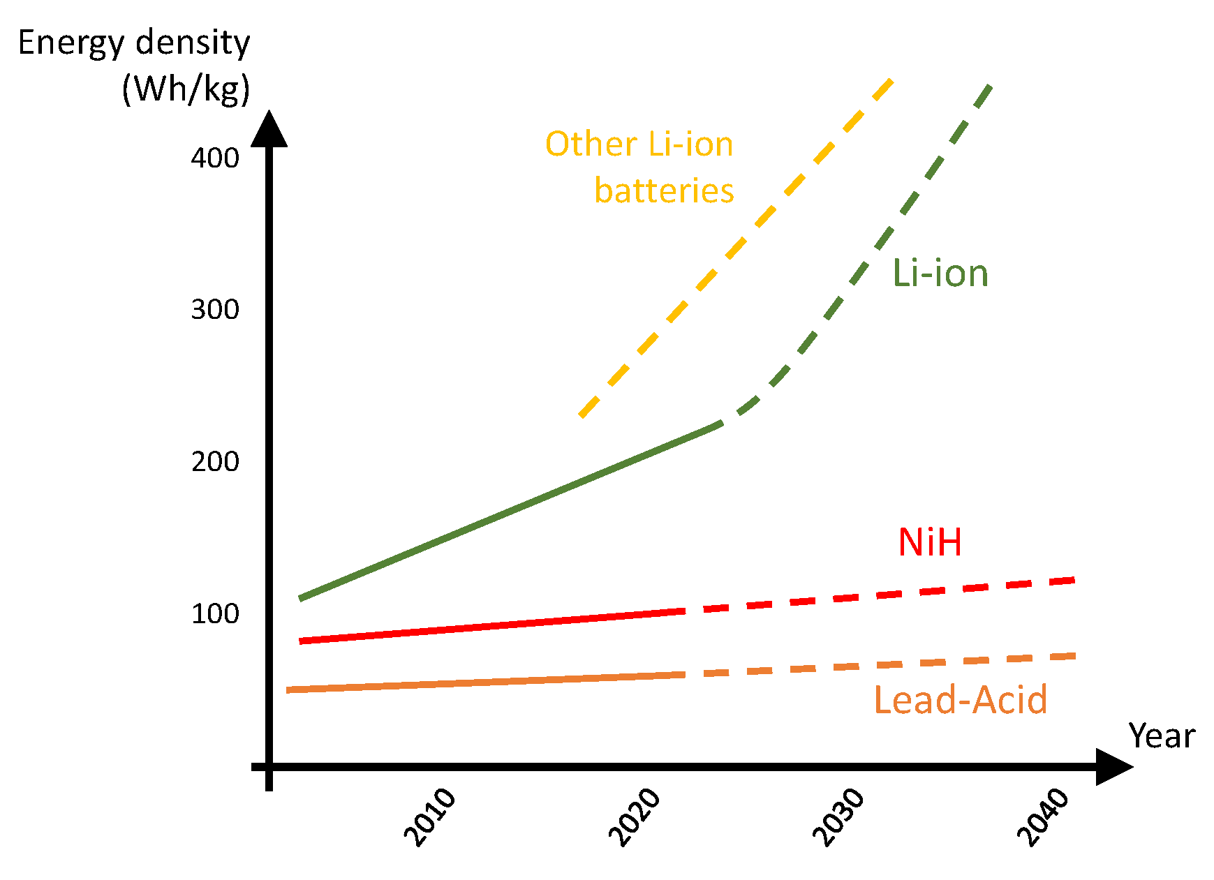
Figure 1. Energy density feature for various typical battery technologies in automotive sector and expected future trend (adapted from [33]).
Thermo 01 00010 g001
Figure 2. Energy flows in a hybrid powertrain.
Thermo 01 00010 g002
Figure 3. Schematic diagram of a typical hybrid transmission system.
Thermo 01 00010 g003
Figure 4. Typical architecture of an HEV with full-hybridization level.
Thermo 01 00010 g004
Figure 5. Vehicle-to-home capability.
Thermo 01 00010 g005
Figure 6. Series configuration of an HEV.
Thermo 01 00010 g006
Figure 7. Parallel configuration of an HEV.
Thermo 01 00010 g007
Figure 8. Mixed configuration of an HEV.
Thermo 01 00010 g008
Figure 9. p / V diagram of the Otto cycle.
Thermo 01 00010 g009
Figure 10. Thermal efficiency of the Otto cycle as function of the specific-heat and compression ratios.
Thermo 01 00010 g010
Figure 11. p / V diagram of the Atkinson cycle.
Thermo 01 00010 g011
Figure 12. p / V diagram of the Miller cycle.
Thermo 01 00010 g012
Table 1. Summary of characteristics of various type of vehicles [19].
FuelDriving Range (km)Annual Fuel Cost (USD)
Compact and SmallMid and Large
All electric94–360320–650600–950
Plug-in hybrid500–800480–1000750–2800
Fuel cell electric570600NA
Ethanol450–660480–8601900–2900
Table 2. Characteristics of various commercial HEVs.
Vehicle ModelElectric Autonomy (km)BatteriesType
Mercedes Class A 250e77Li-ion 15.6Plug-in
Toyota RAV4 Plug-in Hybrid75Li-ion 18.1Plug-in
Suzuki Across75Li-ion 18.1Plug-in
Volkswagen Golf eHybrid71Li-ion 13.0 kWhPlug-in
Mercedes B 250 e70Li-ion 15.6 kWhPlug-in
Mercedes CLA 250 e69Li-ion 15.6 kWhPlug-in
Range Rover Evoque P300e66Li-ion 15.0 kWhPlug-in
Table 3. Comparison of energy densities of various fuels and battery technologies (adapted from [20]).
Fuel/TechnologyEnergy Density (MJ/kg)
Gasoline45
Diesel45
Hydrogen120
Lead-Acid0.11–0.18
Li-ion0.54–1.08
NiCd0.11–1.26
Table 4. Summary of the advantages and disadvantages of the different architectures for HEVs.
ArchitectureAdvantagesDisadvantages
Series
  • Efficient operation of the ICE.
  • Good performance at low speeds.
  • Simpler control of the ICE.
  • Many components.
  • Bad performance at high speeds.
  • Low efficiency.
Parallel
  • No necessity of electric generator.
  • ICE reduced size.
  • Control of the ICE is more complex.
Mixed
  • Great flexibility.
  • High efficiency.
  • Very complex architecture involving many components.
Publisher’s Note: MDPI stays neutral with regard to jurisdictional claims in published maps and institutional affiliations.