Article

A Novel Capacitive Model of Radiators for Building Dynamic Simulations

by
Francesco Calise
,
Francesco Liberato Cappiello
,
Luca Cimmino
*,†,
Massimo Dentice d’Accadia
and
Maria Vicidomini
Department of Industrial Engineering, University of Naples “Federico II”, P.le Vincenzo Tecchio, 80, 80125 Napoli, Italy
*
Author to whom correspondence should be addressed.
These authors contributed equally to this work.
Submission received: 3 February 2025 / Revised: 3 March 2025 / Accepted: 8 March 2025 / Published: 11 March 2025
(This article belongs to the Special Issue Innovative Technologies to Optimize Building Energy Performance)

Abstract

:
This study addresses the critical challenge of performing a detailed calculation of energy savings in buildings by implementing suitable actions aiming at reducing greenhouse gas emissions. Given the high energy consumption of buildings’ space heating systems, optimizing their performance is crucial for reducing their overall primary energy demand. Unfortunately, the calculations of such savings are often based on extremely simplified methods, neglecting the dynamics of the emitters installed inside the buildings. These approximations may lead to relevant errors in the estimation of the possible energy savings. In this framework, the present study presents a novel 0-dimensional capacitive model of a radiator, the most common emitter used in residential buildings. The final scope of this paper is to integrate such a novel model within the TRNSYS 18simulation environment, performing a 1-year simulation of the overall building-space heating system. The radiator model is developed in MATLAB 2024b and it carefully considers the impact of surface area, inlet temperature, and flow rate on the radiator performance. Moreover, the dynamic heat transfer rate of the capacitive radiator is compared with the one returned by the built-in non-capacitive model available in TRNSYS, showing that neglecting the capacitive effect of radiators leads to an incorrect estimation of the heating consumption. During the winter season, with a heating system turned on from 8 a.m. to 4 p.m. and from 6 p.m. to 8 p.m., the thermal energy is underestimated by roughly 20% with the commonly used non-capacitive model.

1. Introduction

The urgent necessity to reduce greenhouse gas (GHG) emissions from the residential sector has become a global critical issue [1]. The residential sector is responsible for about 30% of global final energy consumption and contributes to 26% of global energy-related emissions [2], primarily due to heating and cooling demands [3]. Heating, ventilation, and air conditioning (HVAC) systems are essential for regulating indoor air temperature, humidity, and quality in both residential and non-residential buildings [4]. The energy consumption of these systems plays a significant role in the overall energy usage of buildings, contributing to considerable environmental impacts [5]. As part of the EU “Green Deal” policy, there is a strong focus on reducing the primary energy demand of space heating systems to lessen their environmental footprint and promote sustainability [6]. Addressing this challenge requires the development of more efficient and sustainable heating systems [7], alongside the implementation of accurate dynamic simulation models to understand and optimize the interaction between buildings and their heat generation systems [8].
Dynamic simulation models are essential tools for predicting the energy performance of buildings and their heating systems [9]. These models help in understanding the transient behavior of energy systems, enabling the design and optimization of more efficient heating solutions [10]. Accurate dynamic simulation models can assess the impact of various retrofitting strategies and advanced heating technologies, thereby supporting decision-making processes aimed at reducing energy consumption and GHG emissions [11].
Several studies have demonstrated the effectiveness of dynamic simulation models in evaluating building energy demand and retrofitting strategies, focusing on different aspects of energy retrofit [12]. In a similar vein, other research efforts have concentrated on the simulation of generation systems rather than on the thermal behavior of radiators [13]. Additional studies have also employed TRNSYS to analyze generation components, emphasizing their impact on overall system performance [14]. Furthermore, some works have extended these simulations to encompass various aspects of generation equipment dynamics, yet they fall short of addressing the transient behavior of radiators [15]. Finally, recent analyses have again prioritized generation equipment in their TRNSYS models, leaving a gap in our understanding of radiator performance [16].
However, despite the remarkable analyses, these studies assume that the heat transfer from the emitter to the ambient occurs instantaneously at rated power when the heat generator is turned on, overestimating the efficiency of the emission system [17], and neglecting real dynamics of the coupling between the heating system and thermal zone. The thermal inertia due to the radiator mass is completely neglected in the conventional approach based on the radiator time and the transient time needed to bring the ambient temperature up to the set point is underestimated. This approach aligns with the growing interest in integrating thermal storage solutions within residential heating systems to achieve more stable and efficient operation [18].
An accurate characterization of thermal emitters, such as radiators, is crucial for developing reliable dynamic simulation models [19]. Radiators play a crucial role in the thermal comfort and energy efficiency of heating systems [20]. Understanding their thermal behavior under different operating conditions is essential for optimizing their performance and reducing overall energy consumption [21]. Many studies propose dynamic heat transfer analyses of heating systems in buildings with radiators as heating terminals. However, none of them have managed to propose a capacitive model for the emitters, possibly leading to a misunderstanding of the dynamic behavior of the system and miscalculating the heating energy required during the winter season [22].
Studies focusing on the thermal characterization of radiators have provided valuable insights into their performance. For instance, Liu et al. [23] investigated the heating performance of various types of radiators at low temperatures. The study is based on laboratory tests and examines the deviation between predicted heat output values and actual test results. It provides a correction coefficient table for radiators that can be directly used by designers to improve result accuracy. Additionally, the paper compares the heating effects of radiator heating and floor radiant heating using a TRNSYS computing platform. The results show that, under the same heat source conditions, the corrected radiator heating performs similarly to floor radiant heating, proving the correction validity for low-temperature applications.
Rahmati et al. [24] investigated the thermal performance of a modified hot water radiator through both experimental and numerical methods. The study focuses on improving the heat output of radiators by adding fins to enhance convection. The modified radiator design, featuring five fins, was tested for different input water temperatures and flow rates. The experimental results were validated against numerical simulations using Computational Fluid Dynamics (CFD). The modified radiator showed a 45% increase in heat output compared to the original design. The study also includes a three-dimensional analysis of temperature distribution in a room using the lattice Boltzmann method.
The concept of capacitive radiators introduces an innovative approach to enhancing the thermal performance of radiators [25]. The capacitive nature of radiators is crucial to understanding how thermal energy is gradually released in indoor ambience, rather than instantaneously, as incorrectly assumed in many simulation models [26]. Assuming a non-capacitive behavior of the radiator determines an overestimation of the heat released to the air node of the thermal zone, causing a fictitious increase in the zone indoor temperature, at the activation of the space heating system. Similarly, when the space heating system is turned off, the use of a non-capacitive model of the radiator determines a non-realistic fast decrease in the indoor zone air temperature, whereas the empirical data show a smooth decrease in such parameters. The overall result is also an inaccurate estimation of the heat released to the air zone by the radiator during the unsteady operation, especially at the time of the activation and deactivation of the space heating system. Many relevant studies in literature perform accurate dynamic analysis of buildings including heat generation and high-temperature emitters, using several tools such as EnergyPlus [27], Modelica [28], TRNSYS [29], IDA ICE [30] and many others [31]. In this framework, Mazzeo et al. [32] evaluated the accuracy of three building simulation tools—TRNSYS, EnergyPlus, and IDA ICE—by comparing their predictions with experimental data from solar test boxes, one of which includes a Phase Change Material (PCM). The study finds that IDA ICE provides the most accurate results when simulating the thermal behavior of buildings with PCM due to its ability to model PCM hysteresis. EnergyPlus performs well but is slightly less accurate, while TRNSYS, though less precise, is suitable for preliminary evaluations due to its lower computational cost. Despite this, issues are posed when TRNSYS is used for dynamic simulation of buildings, due to the lack of capacitive models for high-temperature emitters.
The aim of this study is to provide a comprehensive analysis of the heat transfer phenomena occurring in the radiators during thermal transients. In fact, the capacitive effect of radiators is not presently considered in commercially available dynamic simulation models and it is therefore investigated in this work to provide useful and easy-to-integrate mathematical models for energy systems analysis. This study analyzes the performance of an aluminum radiator under varying conditions. The relevance of the study is in highlighting the significance of choosing appropriate design parameters for radiators to optimize thermal performance and efficiency.

2. Materials and Methods

This section presents the method adopted to perform the analysis and describes the developed model of the capacitive radiator.

2.1. Research Method

The capacitive radiator model idea arises from the necessity of integrating a more accurate model in the TRNSYS environment to perform dynamic analyses also considering the transient heat transfer rate of the emitter in the ambient [33]. The model was developed by assuming energy balance on the radiator and integrating the equations in MATLAB to solve the transient heat transfer. The model developed is 0-D for easier integration in the TRNSYS platform for one-year dynamic simulation purposes.

2.2. Radiator Model

This section discusses the key components and processes involved in the thermal balance equation for the aluminum radiator control volume. Heat transfer occurs between the water (with inlet temperature Tw,in) and the material, as well as between the radiator surface and the surrounding environment (ambient temperature Ta). The differential equation governing this system is derived from the energy balance, accounting for the inlet water temperature, mass flow rate, and ambient temperature. In this model, some simplifying assumptions are made:
  • Constant fluid properties: fluid properties like specific heat (Cp) and density (ρ) are assumed constant, ignoring their temperature dependence.
  • Local Thermal Equilibrium: no significant delays in heat transfer between the fluid and the radiator.
  • Neglect of gravitational and kinetic terms: the influence of gravity (buoyancy effects) and kinetic energy changes in the water flow (due to speed variations) are not included in the calculations.
  • Steady-state assumption for heat transfer: The heat transfer coefficients (hi and he) and thermal conductivity (k) are constant over time.
  • Constant ambient conditions: Room temperature is fixed at 20 °C.
To solve the energy balance, a system of three equations was developed as follows:
M w C p , w d T w d ϑ = m ˙ w C p , w T w , i n T w , o u t U i A r a d T w T r a d M r a d C p , r a d d T r a d d ϑ = U i A r a d T w T r a d U e A r a d T r a d T r o o m M a i r C p , a i r d T a i r d ϑ = U e A r a d T r a d T r o o m U w a l l A w a l l T r o o m T a m b
where Mw, Mrad, and Mair, are, respectively, the mass of water, aluminum, and air in the room; Cp is the specific heat; Ui and Ue are, respectively, the heat transfer coefficients for the inside and outside of the radiator, whereas Uwall is the heat transfer rate between the wall of the room and external environment; Mw is the mass of water in the pipe, Mrad is the mass of the radiator, and Mair is the mass of the air in the room considered. This system of differential equations describes how the average water temperature Tw (Tw = Tw,avg = (Tw,in + Tw,out)/2), the radiator temperature Trad, and the air temperature Tair evolve over time in response to the heat input from the inlet water temperature and the heat transfer to the radiator and to the room.
The terms on the right side of system of the Equation (1) are:
  • Enthalpy flow rate: This is the enthalpy of the water flow throughout the radiator:
m w C p , w T w , i n T w , o u t
where mw is the mass flow rate of water (kg/s), Cp,w is the specific heat capacity of water (kJ/kg·K), Tw,in is the inlet water temperature (assumed constant), and Tw,out is the outlet water temperature.
2.
Heat transfer from water to radiator: This is the heat transfer rate from the water node, assumed as the average between the inlet and outlet, and the radiator node:
U i A r a d T w T r a d
where Trad is the temperature of the radiator, Arad is the surface area of the material (m2), and the heat transfer coefficient Ui is calculated as:
U i = 1 1 h i + s k
where hi is the internal heat transfer coefficient between the water and the radiator, s is the thickness of the radiator, and k is thermal conductivity of the radiator material.
3.
Heat transfer from radiator to room: This term represents the heat transferred from the radiator to the thermal zone:
U e A r a d T r a d T r o o m
where Ue is the overall heat transfer coefficient (W/m2K), sum of the convective and radiative contributions, and Troom is the room temperature (°C).
The internal heat transfer coefficient is calculated using correlations for the forced convection in turbulent flow, assuming a hydraulic diameter for a rectangular cross-section [34]. The external heat transfer coefficient is calculated as the sum of the convective and radiative heat transfer coefficients. Specifically, the convective term is calculated assuming natural convection for vertical walls and iteratively calculating the flow regime, according to the temperature evolution [35]. The radiative term is calculated according to the Stefan Boltzmann equation [36], assuming the radiator is a grey body with diffuse surfaces, view factors equal to 1, and a lumped radiative-convective single heat transfer coefficient.
The MATLAB code developed is designed to analyze the sensitivity of the aluminum radiator to varying surface areas, inlet temperatures, and flow rates in a heat exchange scenario. The dynamic model for the capacitive radiator employs an ordinary differential equation (ODE) approach using MATLAB ode15s solver. This solver was chosen for its robustness in handling stiff systems, which is characteristic of transient heat transfer problems [37]. However, it is important to note that ODE-based methods, particularly in the context of dynamic simulations, can be computationally demanding. The fine temporal resolution required to accurately capture rapid transient phenomena often results in increased simulation times [38].
Furthermore, convergence issues can arise in such systems, especially when abrupt changes occur in the input parameters or during rapid thermal transients. These convergence challenges are typically managed by adjusting solver parameters—such as using adaptive time-stepping and setting stricter error tolerances—to balance accuracy and computational efficiency [39]. Despite these challenges, the use of an ODE-based approach is justified by its ability to capture the detailed dynamics of the radiator, providing insights that simpler, steady-state models cannot offer [40].
Table 1 summarizes all the parameters used in the simulation model to analyze the transient behavior of the radiator.

3. Results

This section presents the results of the simulations performed in MATLAB, with a timestep of 0.05 s. First, the simulation of the model for the transient phase for an aluminum radiator is presented, together with the validation against technical data provided by manufacturers. Then, the sensitivity analysis under different parameter variations is discussed. In conclusion, the comparison with the heat transfer rate calculated in TRNSYS is performed. The TRNSYS simulation is performed by developing a model for a test case, consisting of a simple cubic building, in TRNBuild, located in Naples, Southern Italy, which dynamically interacts with the surrounding ambient. Details of this modeling approach and building data are referred to in [15].

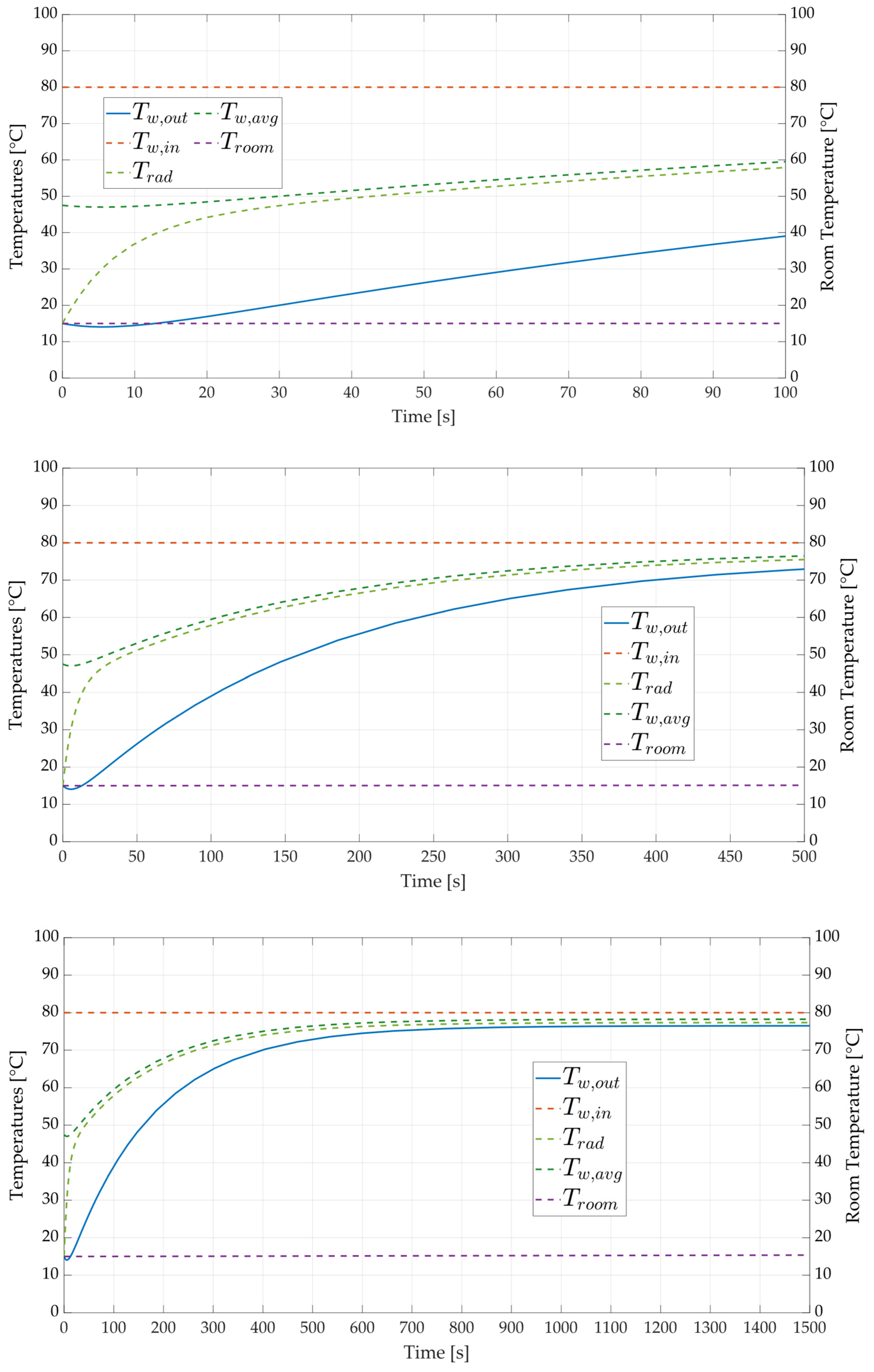
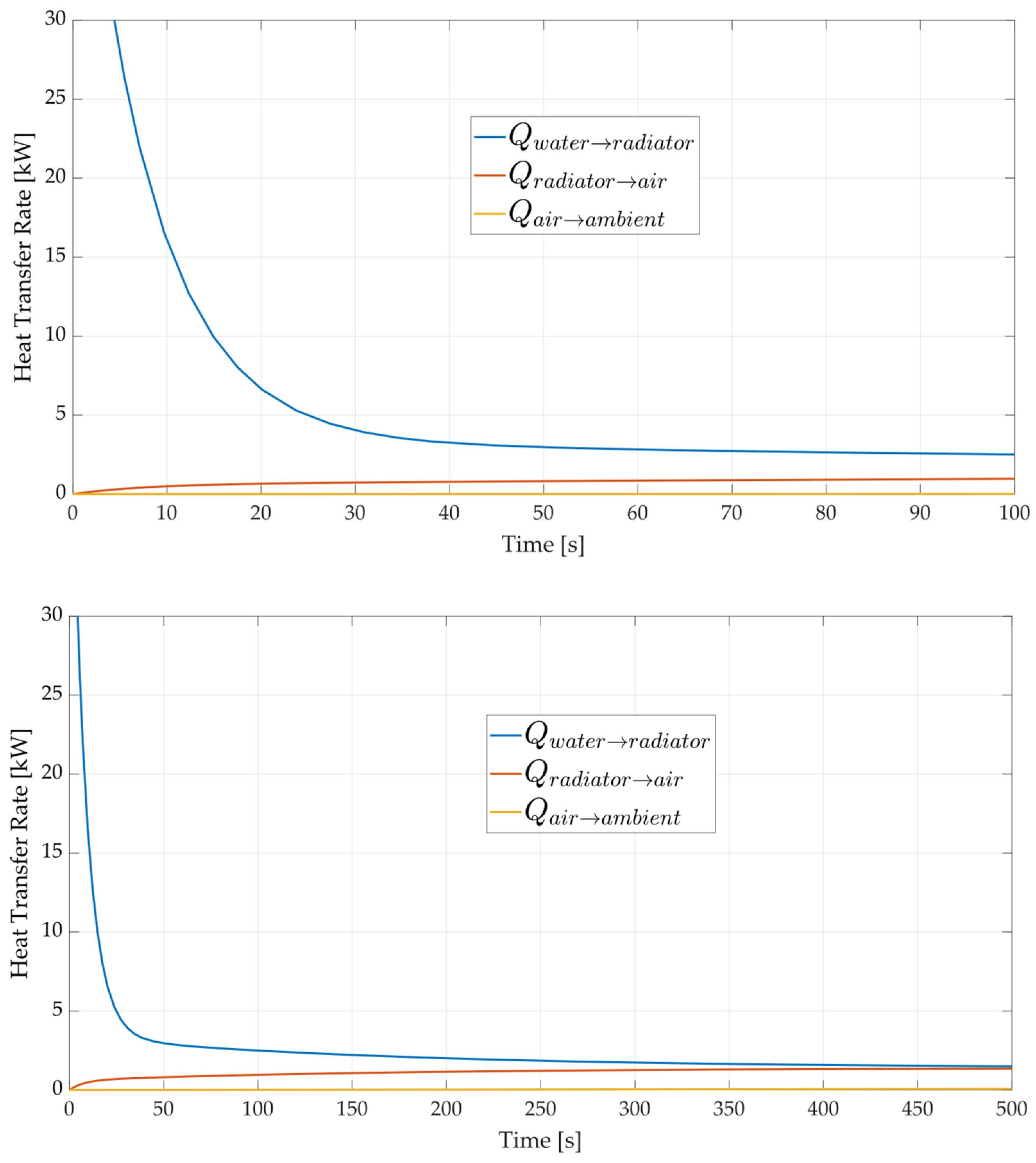
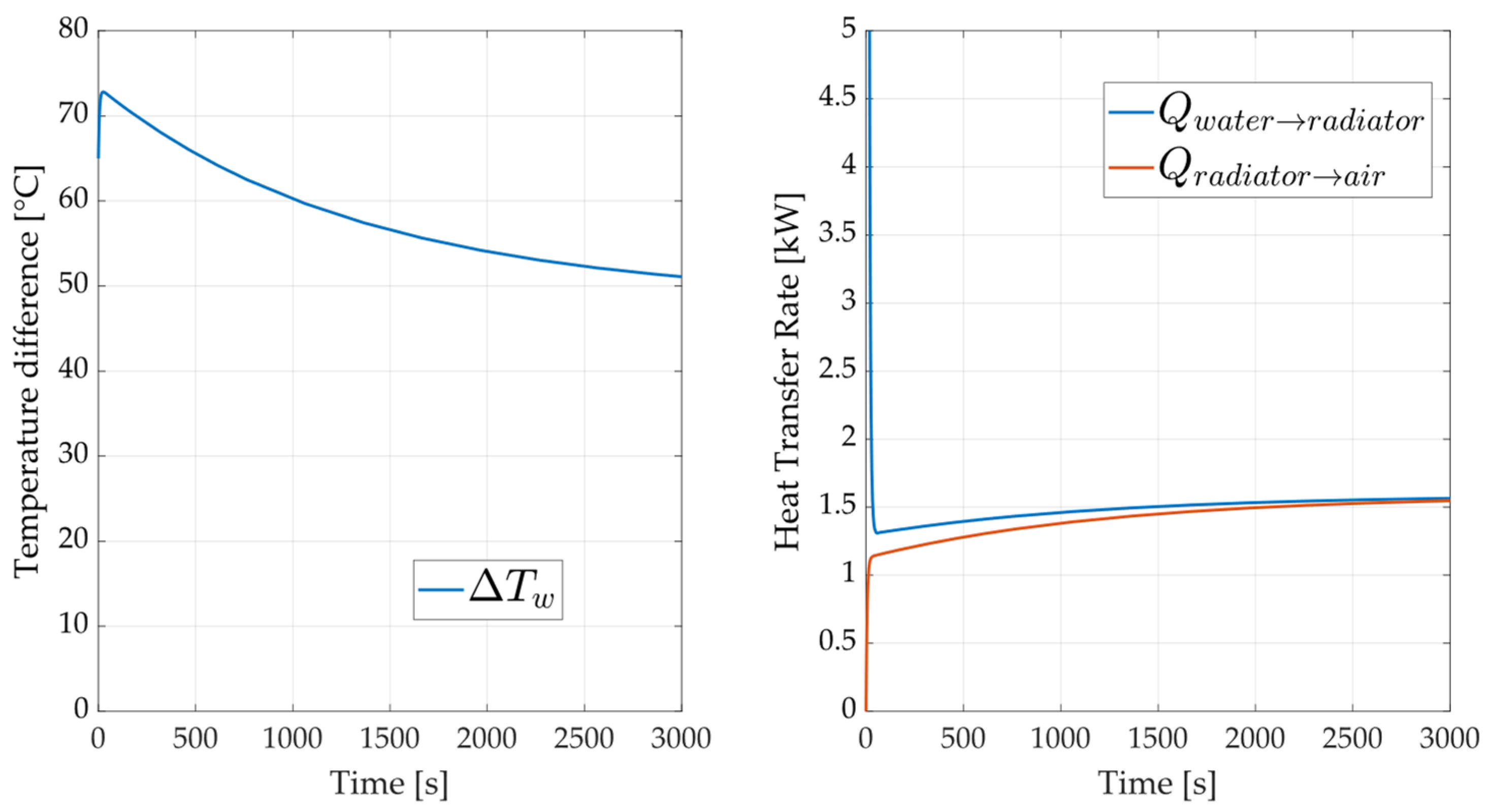
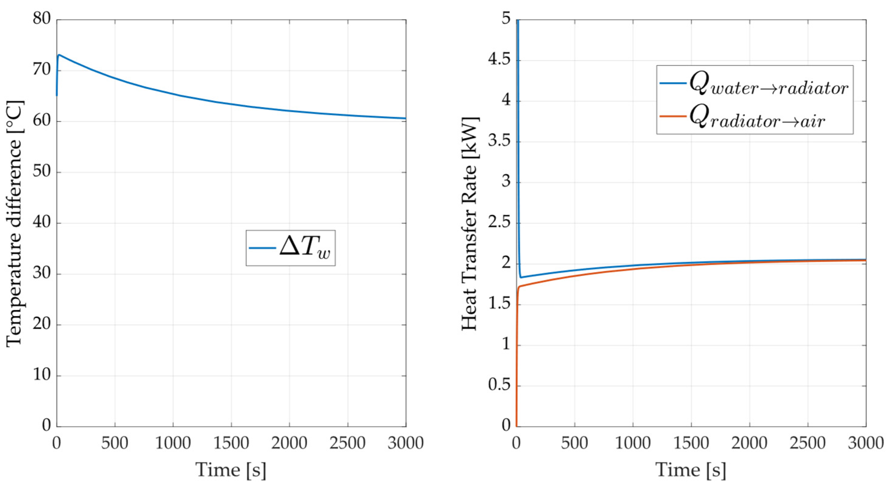
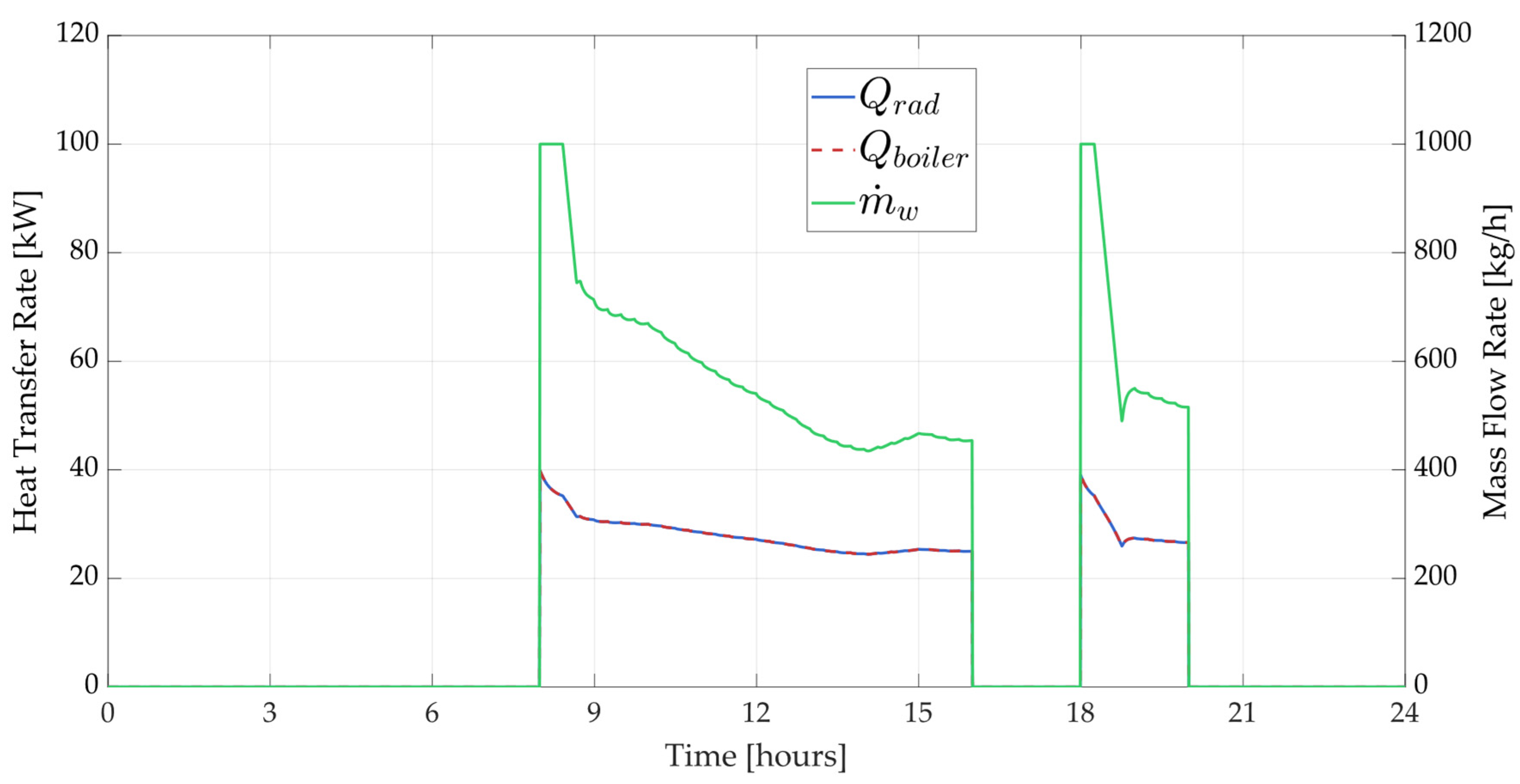
3.1. Transient Heat Transfer Rate

Figure 1 shows the transient temperature evolution for an A6063 aluminum alloy radiator after different observation times. The inlet temperature is equal to 80 °C and is an input parameter to the system, in line with inlet temperature values for residential-use radiators [41]. This temperature is the driver of the heat transfer process. As the hot water flows through the radiator, it transfers heat to the radiator material. The heat transfer rate is governed by the difference in temperature between the water and the ambient air, as well as the thermal inertia of the radiator, according to Equation (1), and is totally neglected in common dynamic models [22].
As the water transfers heat to the radiator and ambient air, its temperature drops. The outlet temperature (Tw,out) first drops to a very low value, due to the heat transfer occurring from the water to the radiator, increasing the radiator surface temperature. This transient phase occurs for roughly 500 s (eight minutes) in the model and the outlet water temperature at the end is nearly 72 °C. It is worth noting that, according to the model, the water outlet temperature is not the temperature of the water node, which is instead the average water temperature (Tw,avg). Underscoring this point is pivotal in order to not misunderstand the operation of the model developed. In fact, the second law of thermodynamics is definitely respected by the model since the water node is always at a higher temperature than the radiator node (Tw,avg is greater than Trad at every step). Here, Tw,out is a local value of temperature, determined as the output of the system of Equation (1), while Trad is a mediated value of the radiator over the area. In a 1-D model, it would be possible to observe how the Trad is actually always lower than the Tw,out for every slice of the radiator.
The surface temperature of the radiator (Trad) also increases by means of the heat transfer from the water to the radiator, aligning to the average between inlet and outlet water temperature when steady-state conditions are reached. At the same time, the radiator transfers heat to the surrounding air, which is essential for space heating. The surface temperature tends to stabilize as the system reaches thermal equilibrium. In this case, the room temperature slightly increases. To observe the full transient temperature of the room, a much longer time horizon should be observed. In this case, the simulation showed that the room temperature stabilizes at 15 °C after roughly 1500 s, i.e., nearly one and a half hours.
Figure 2 shows the heat transfer rates from the water to the radiator and from the radiator to the environment, for the same observation times, confirming the previous analysis. At the beginning of the process (t = 0), the water entering the radiator is at its maximum temperature, while the outlet temperature rapidly decreases as heat is transferred to the radiator and ambient air. Over time, the system approaches a steady state where the temperatures stabilize. The outlet temperature and surface temperature reach a point where the heat input and heat loss are balanced. The steady state occurs when the temperature of the water exiting the radiator stabilizes, and the radiator surface temperature remains constant. At this point, the system is in thermal equilibrium, with a continuous but balanced flow of energy from the hot water through the radiator to the environment.

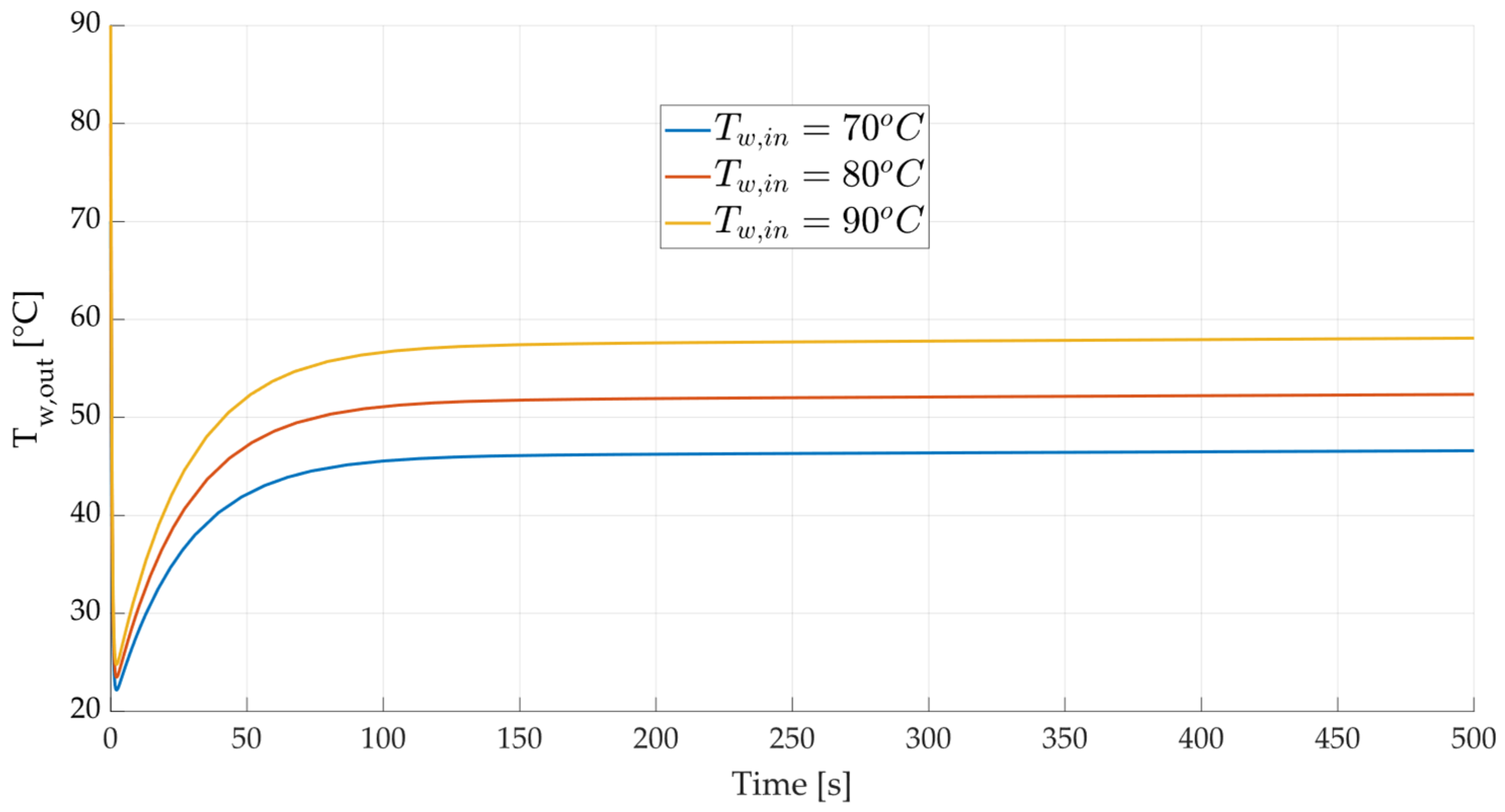
3.2. Sensitivity Analysis

Figure 3, Figure 4 and Figure 5 show the results of the sensitivity analysis when some main parameters are varied, namely total surface area (from 5.48 m2 to 16.44 m2), inlet water temperature (from 70 to 90 °C), and water flow rate (from 250 kg/h to 1000 kg/h).
Figure 3 examines the sensitivity of the outlet water temperature (Tw,out) to variations in the surface area (A). Surface area is a critical factor in determining heat transfer efficiency from the water inside the radiator to the surrounding environment.
As expected, the larger the surface area, the more extensive the contact between the radiator and the air, leading to more efficient heat dissipation. In aluminum radiators, increasing the surface area from 5.48 m2 to 16.44 m2 results in a noticeable reduction in Tw,out, more than 20 °C, indicating that aluminum’s high conductivity amplifies the impact of increased surface area on heat dissipation.
Figure 4 focuses on how variations in inlet temperature (Tw,in) affect the outlet water temperature (Tw,out). The inlet temperature is a crucial factor because it determines the initial thermal energy available for transfer. Higher inlet temperatures naturally lead to higher outlet temperatures. This is because the thermal energy content of the water increases with temperature, providing a larger energy gradient for heat transfer. The temperature drops gradually, indicating that the material absorbs and retains more heat before reaching a steady state.
Figure 5 evaluates the impact of varying the water flow rate (w) on the outlet temperature. Flow rate is a significant factor because it controls the rate at which thermal energy is transported through the radiator. The greater the water flow rate, the higher the outlet water temperature, as expected.

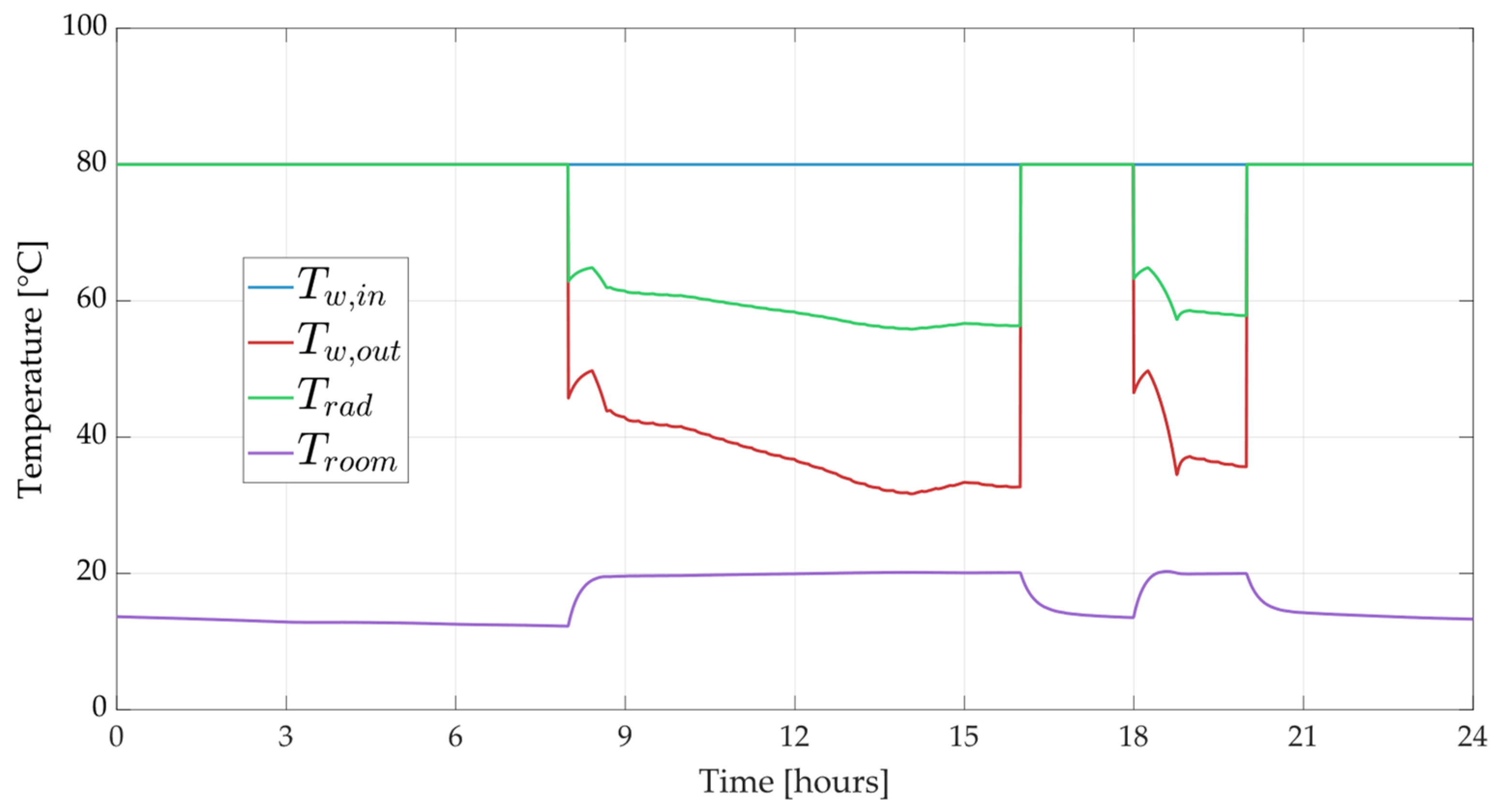
3.3. Model Validation

Due to the lack of experimental data, the model was validated by comparing its performance against the design specifications provided in manufacturers’ technical datasheets. In particular, the radiator model was calibrated using the geometrical and thermodynamic parameters specified in the Helyos Evo 2000 aluminum radiator datasheet [42]. Figure 6, Figure 7 and Figure 8 illustrate the model performance by showing the heat transfer rate and the temperature difference (ΔT) between the radiator and the environment under rated operating conditions.
For each operating condition provided in the datasheet (ΔT = 30 °C, 50 °C, and 60 °C), a specific thermal output per radiator element is expected—83.9 W, 164.7 W, and 209.5 W—respectively [42]. By incorporating the model with the corresponding geometric features and the desired number of elements, the simulated heat transfer values for each ΔT are consistent with the manufacturer’s specifications (840 W, 1.6 kW, and 2.1 kW, respectively). To ensure that the conditions observed represent the steady-state design operation, the plots display results after 3000 s of simulation (approximately one hour of operation).

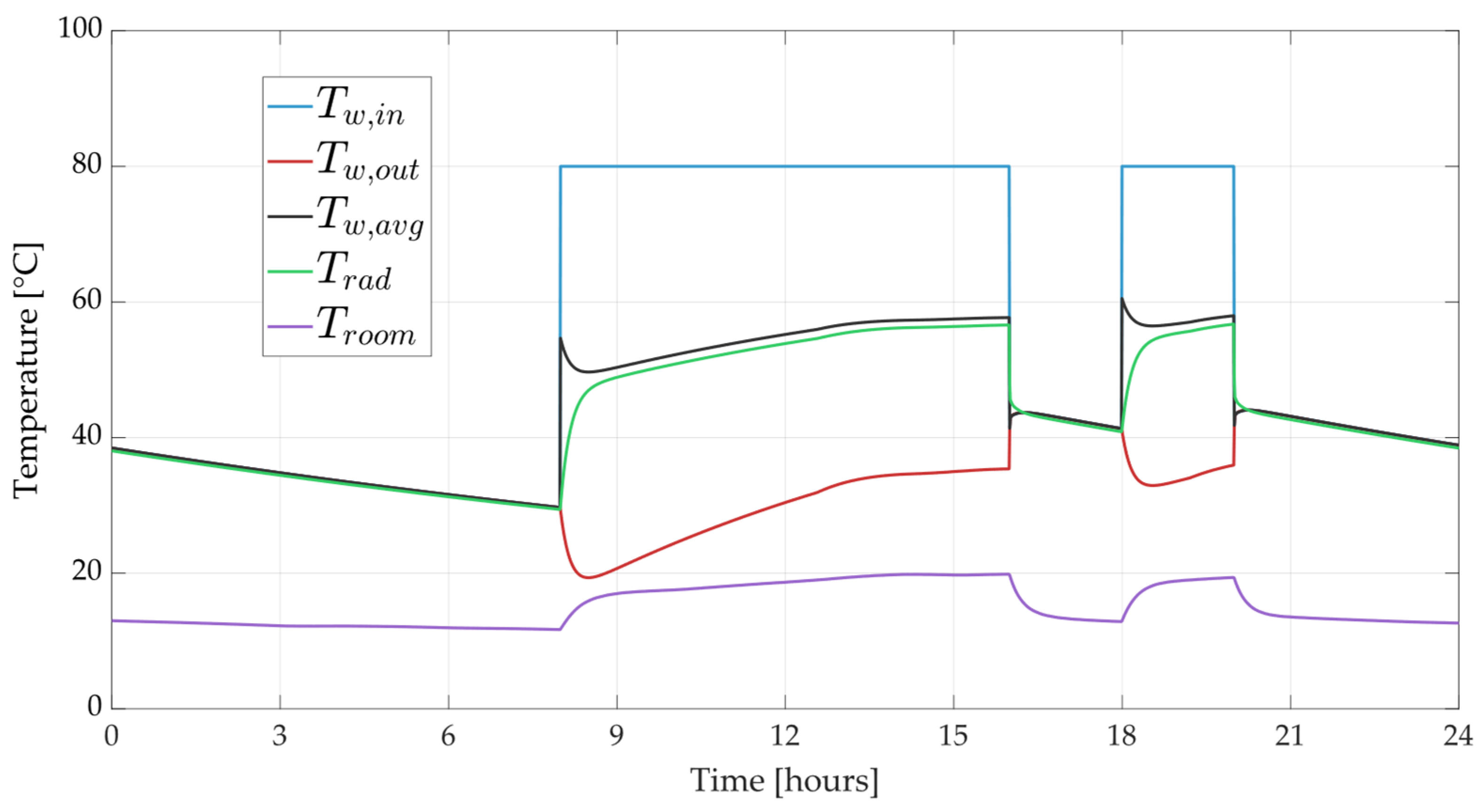
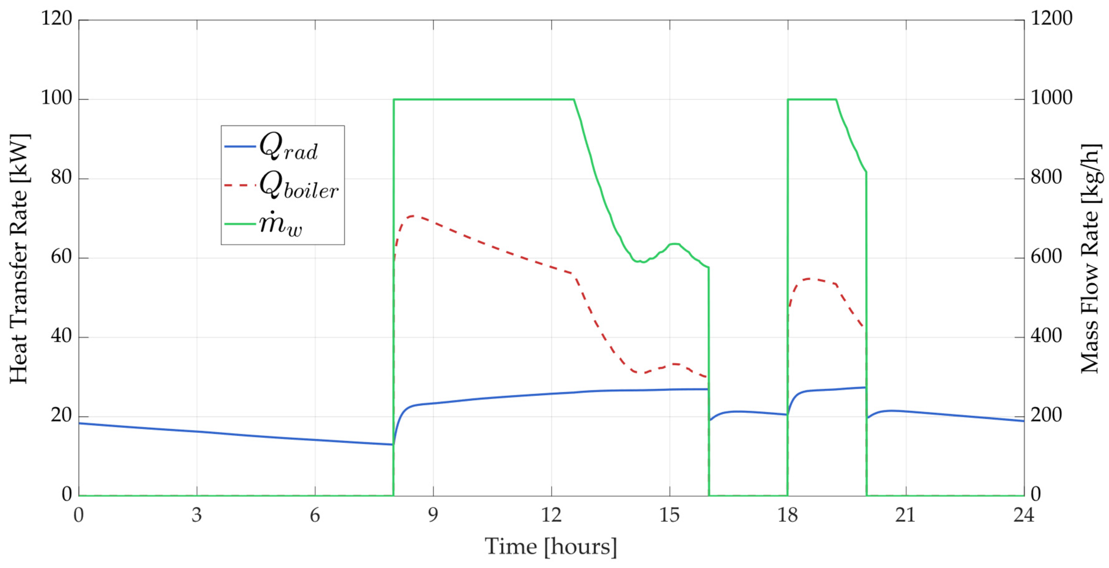
3.4. Comparison with TRNSYS Simulation Model

Figure 9, Figure 10, Figure 11 and Figure 12 show, respectively, the trends of the temperatures and heat transfer rates for both the TRNSYS non-capacitive model (Figure 9 and Figure 10) and the capacitive in-house developed model (Figure 11 and Figure 12).
The dynamic simulation in TRNSYS includes the activation of the radiators according to the internal ambient temperature, the occupancy profile of the inhabitants in the room, and the heating season. Specifically, the activation of the radiators on this selected winter day occurs two times: from 8:00 a.m. to 4:00 p.m. and from 6:00 p.m. to 8:00 p.m. [15]. The heating system is a boiler fed by natural gas supplied by the gas grid.
Heating control occurs by means of a water flow regulation, whereas the inlet water temperature is set constant and equal to 80 °C. Given the dynamics of the TRNBuild simulated model, the room temperature is continuously varying, as a consequence of the varying ambient conditions and the heat dissipation of the building. The different outcomes are clear. The outlet water temperature (Tw,out) in the case of the TRNSYS model instantly drops to respond to the heat transfer rate requested by the room, to bring the temperature up to the design set point (20 °C). Conversely, the outlet water temperature obtained from the model proposed first presents a sharp decrease due to the thermal inertia of the radiator and then shows a smooth decreasing trend. This is consistent with what is expected from a model that considers the capacitive effect due to the mass of the radiator. Accordingly, the room temperature (Troom) increase is smoother in the case of the capacitive radiator, see Figure 9 and Figure 10. Once the heater is turned off, at 4:00 p.m., the capacitive radiator model shows a smoother decrease in the water outlet temperature resulting in a smoother decrease in the air temperature. Conversely, in the case of the non-capacitive (TRNSYS) model, all the temperatures immediately rise up to the inlet water temperature value, which is clearly unrealistic. The outlet water temperature of the radiator (Tw,out) is below the radiator temperature (Trad) because of the way it is calculated according to the model (see Equation (1)). The heat transfer balance is correct since the water temperature node (Tw,avg) is always greater than Trad.
The trends of heat transfer rates in Figure 11 and Figure 12 confirm what was hitherto observed. The heat transfer rate provided by the boiler (Qboiler) has a much higher peak in the case of the capacitive model, due to the necessity of heating the radiator first (see Tw,out in Figure 8). Then, the heat transfer rate decreases to a slightly lower value than the non-capacitive case, in agreement with the water flow rate w. The trend of the radiator and water outlet temperatures is also confirmed by the heat released from the radiator to the room (Qrad), showing a much smoother increase precisely due to its capacitive effect. This translates into a smoother increase in the room temperature, as shown in Figure 8.
The differing behavior of the two models highlights the distinct dynamics involved in each case. When a capacitive radiator model is used, the heat transfer from the boiler to the radiator is out of sync with the heat transfer from the radiator to the surrounding environment. In contrast, with a non-capacitive radiator model, these two heat transfer processes are perfectly aligned, entirely neglecting the system’s real dynamics.
This discrepancy becomes particularly significant when analyzing the system’s impact on occupant comfort or when integrating it with renewable energy sources [15]. Furthermore, the one-year simulation reveals that, while the difference in heat delivered by the radiator to the room is minimal, the total heat supplied by the boiler differs significantly. In the capacitive model, additional heat is needed to warm the radiator itself, resulting in a 20% increase in thermal energy demand during the winter season.

4. Discussion

The results of this study provide essential insights into developing a more accurate radiator model for dynamic simulations in TRNSYS. The model developed is a lumped parameter physics-based model describing heat transfer phenomena within the radiator and between the radiator and the indoor environment. The study is conducted on a deterministic mathematical model that does not account for stochastic variability. The robustness of the model is based on the physical principles of the heat transfer theory and enhanced by the sensitivity analysis that shows consistent behavior of the model when the key variables are varied. The findings confirm that surface area, inlet temperature, and flow rate significantly influence the radiator performance, with these effects varying based on the material thermal conductivity and mass. Moreover, the results in terms of dynamics when considering a capacitive radiative model rather than a simplified non-capacitive one differ significantly [43]. The difference between the models might also cause a mistake in the calculation of the total thermal energy required during the winter season by the system to heat the ambient. In this case, a 20% increase in thermal energy consumption for the boiler was found for the capacitive model. This increase is due to the necessity of heating the radiator first, which then releases heat to the ambient more smoothly, when heating is not required, causing an overall increase in energy consumption.
The results obtained in this case study are in line with the expectations, proving that the model is accurate. The model was validated against design operating conditions under specific design parameters and variables provided by manufacturers’ datasheets. Additionally, the capacitive radiator model was indirectly validated through a rigorous sensitivity analysis and by comparing its performance with a well-established non-capacitive model implemented in TRNSYS. These comparisons demonstrated that the capacitive model more accurately mimics the transient thermal behavior of radiators. However, further experimental validation is essential to confirm the model’s accuracy under real-world conditions. To this end, future work will include the setup of an experimental benchmark aimed at calibrating and validating the model, thereby enhancing its robustness and practical applicability in building energy simulations.
These results underscore the importance of incorporating the capacitive effects of radiators into dynamic simulation models. Traditional models often assume instantaneous heat transfer, which fails to capture the transient behavior observed in real-world conditions [44]. By integrating the transient dynamics highlighted in this study, a novel radiator model was developed in TRNSYS that more accurately simulates the thermal behavior of different radiator materials under varying operational conditions. This enhanced model will improve the precision of HVAC system simulations, leading to better optimization of energy consumption and a more accurate assessment of retrofit strategies [45].
Future research should focus on refining this model further by exploring advanced material combinations and validating the simulations against real-world data. This approach will ensure that the TRNSYS model not only reflects theoretical predictions but also performs reliably in practical applications, contributing to more energy-efficient and sustainable building designs.

5. Conclusions

This study developed and analyzed a novel 0-dimensional capacitive model of a water-heated radiator, highlighting the importance of accounting for thermal inertia in dynamic simulations. The model, integrated into a TRNSYS simulation framework, clearly demonstrates that neglecting the capacitive effect of radiators can lead to significant underestimations of thermal energy consumption—by approximately 20% during the winter season—due to the instantaneous heat transfer assumption in conventional non-capacitive models. Key findings include:
-
The capacitive model reveals a distinct transient phase in which the heat transfer from the water to the radiator and from the radiator to the environment is gradual. This results in smoother temperature profiles in both the water outlet and the room air, reflecting a more realistic thermal response.
-
Sensitivity analyses underscore that the radiator performance is strongly influenced by the surface area, inlet water temperature, and water flow rate. These parameters critically determine the efficiency of heat exchange and the subsequent energy demand of the heating system.
-
The discrepancies observed between the capacitive and non-capacitive models indicate that conventional simulation tools may oversimplify the transient dynamics of radiators. By integrating the capacitive effects, the enhanced model offers improved accuracy in estimating heating consumption and assessing the impact of retrofit strategies on energy efficiency.
Overall, the study emphasizes that incorporating the capacitive behavior of radiators into dynamic simulations is essential for reliable predictions of energy performance in building heating systems. Future work should focus on experimental validation and further refinement of the model to encompass additional material characteristics and operating conditions, thereby enhancing its applicability in practical energy efficiency assessments.

Author Contributions

Conceptualization, F.C., F.L.C., L.C., M.D.d. and M.V.; methodology, F.C., F.L.C., L.C., M.D.d. and M.V.; software, F.C., F.L.C., L.C., M.D.d. and M.V.; validation, F.C., F.L.C., L.C., M.D.d. and M.V.; formal analysis, F.C., F.L.C., L.C., M.D.d. and M.V.; investigation, F.C., F.L.C., L.C., M.D.d. and M.V.; resources, F.C., F.L.C., L.C., M.D.d. and M.V.; data curation, F.C., F.L.C., L.C., M.D.d. and M.V.; writing—original draft preparation, F.C., F.L.C., L.C., M.D.d. and M.V.; writing—review and editing, F.C., F.L.C., L.C., M.D.d. and M.V.; visualization, F.C., F.L.C., L.C., M.D.d. and M.V.; supervision, F.C., F.L.C., L.C., M.D.d. and M.V.; project administration, F.C., F.L.C., L.C., M.D.d. and M.V.; funding acquisition, F.C., F.L.C., L.C., M.D.d. and M.V. All authors have read and agreed to the published version of the manuscript.

Funding

Project funded under the National Recovery and Resilience Plan (NRRP), Mission 4, Component 2, Investment 1.3—Call for tender No. 1561 of 11 October 2022 of Ministero dell’Università e della Ricerca (MUR); funded by the European Union—NextGenerationEU. Award Number: Project code PE0000021, Concession Decree No. 1561 of 11 October 2022 adopted by Ministero dell’Università e della Ricerca (MUR), CUP E63C22002160007, Project title: “Network 4 Energy Sustainable Transition—NEST.

Data Availability Statement

No data were required in this research.

Conflicts of Interest

The authors declare no conflicts of interest. The funders had no role in the design of the study; in the collection, analyses, or interpretation of data; in the writing of the manuscript; or in the decision to publish the results.

References

  1. Daioglou, V.; Mikropoulos, E.; Gernaat, D.; van Vuuren, D.P. Efficiency Improvement and Technology Choice for Energy and Emission Reductions of the Residential Sector. Energy 2022, 243, 122994. [Google Scholar] [CrossRef]
  2. Hu, S.; Yang, Z.; Yan, D.; Wang, B.; Jiang, Y. Emissions of F-Gases from Room Air Conditioners in China and Scenarios to 2060. Energy Build. 2023, 299, 113561. [Google Scholar] [CrossRef]
  3. Hingorani, R.; Dittrich, N.; Köhler, J.; Müller, D.B. Müller. Embodied Greenhouse Gas Emissions in Structural Materials for the German Residential Building Stock—Quantification and Mitigation Scenarios. Build. Environ. 2023, 245, 110830. [Google Scholar] [CrossRef]
  4. Krajčík, M.; Arıcı, M.; Ma, Z. Trends in Research of Heating, Ventilation and Air Conditioning and Hot Water Systems in Building Retrofits: Integration of Review Studies. J. Build. Eng. 2023, 76, 107426. [Google Scholar] [CrossRef]
  5. Hewitt, D.; Coakley, S. Transforming Our Buildings for a Low-Carbon Era: Five Key Strategies. Electr. J. 2019, 32, 106624. [Google Scholar] [CrossRef]
  6. IEA. Japan Will Have to Tread a Unique Pathway to Net Zero, but It Can Get There Through Innovation and Investment. Available online: https://www.iea.org/commentaries/japan-will-have-to-tread-a-unique-pathway-to-net-zero-but-it-can-get-there-through-innovation-and-investment (accessed on 6 March 2025).
  7. Zhang, Y.; Liu, M.; O’Neill, Z.; Wen, J. Temperature Control Strategies for Fifth Generation District Heating and Cooling Systems: A Review and Case Study. Appl. Energy 2024, 376, 124156. [Google Scholar] [CrossRef]
  8. Villano, F.; Mauro, G.M.; Pedace, A. A Review on Machine/Deep Learning Techniques Applied to Building Energy Simulation, Optimization and Management. Thermo 2024, 4, 100–139. [Google Scholar] [CrossRef]
  9. Akkurt, G.; Aste, N.; Borderon, J.; Buda, A.; Calzolari, M.; Chung, D.; Costanzo, V.; Del Pero, C.; Evola, G.; Huerto-Cardenas, H.; et al. Dynamic Thermal and Hygrometric Simulation of Historical Buildings: Critical Factors and Possible Solutions. Renew. Sustain. Energy Rev. 2020, 118, 109509. [Google Scholar] [CrossRef]
  10. Shboul, B.; Zayed, M.E.; Ashraf, W.M.; Usman, M.; Roy, D.; Irshad, K.; Rehman, S. Energy and Economic Analysis of Building Integrated Photovoltaic Thermal System: Seasonal Dynamic Modeling Assisted with Machine Learning-Aided Method and Multi-Objective Genetic Optimization. Alex. Eng. J. 2024, 94, 131–148. [Google Scholar] [CrossRef]
  11. Calise, F.; Cappiello, F.; Cimmino, L.; Vicidomini, M. Vicidomini. Semi-Stationary and Dynamic Simulation Models: A Critical Comparison of the Energy and Economic Savings for the Energy Refurbishment of Buildings. Energy 2024, 300, 131618. [Google Scholar] [CrossRef]
  12. de Oliveira, C.C.; Vaz, I.C.M.; Ghisi, E. Retrofit Strategies to Improve Energy Efficiency in Buildings: An Integrative Review. Energy Build. 2024, 321, 114624. [Google Scholar] [CrossRef]
  13. Farrokhi, M.; Motallebzadeh, R.; Javani, N.; Ebrahimpour, A. Dynamic Simulation of an Integrated Energy System for Buildings in Cold Climates with Thermal Energy Storage. Sustain. Energy Technol. Assess. 2021, 47, 101459. [Google Scholar] [CrossRef]
  14. Bordignon, S.; Emmi, G.; Zarrella, A.; De Carli, M. Energy Analysis of Different Configurations for a Reversible Ground Source Heat Pump Using a New Flexible Trnsys Type. Appl. Therm. Eng. 2021, 197, 117413. [Google Scholar] [CrossRef]
  15. Cappiello, F.L.; Cimmino, L.; D’Accadia, M.D.; Vicidomini, M. Dynamic Modelling and Thermoeconomic Analysis for the Energy Refurbishment of the Italian Building Sector: Case Study for the “Superbonus 110%” Funding Strategy. Appl. Therm. Eng. 2022, 213, 118689. [Google Scholar]
  16. D’Agostino, D.; Minichiello, F.; Petito, F.; Renno, C.; Valentino, A. Retrofit Strategies to Obtain a Nzeb Using Low Enthalpy Geothermal Energy Systems. Energy 2022, 239, 122307. [Google Scholar] [CrossRef]
  17. Võsa, K.-V.; Ferrantelli, A.; Kurnitski, J. A Combined Analytical Model for Increasing the Accuracy of Heat Emission Predictions in Rooms Heated by Radiators. J. Build. Eng. 2019, 23, 291–300. [Google Scholar] [CrossRef]
  18. Xu, T.; Humire, E.N.; Chiu, J.N.; Sawalha, S. Latent Heat Storage Integration into Heat Pump Based Heating Systems for Energy-Efficient Load Shifting. Energy Convers. Manag. 2021, 236, 114042. [Google Scholar] [CrossRef]
  19. Gheibi, A.; Rahmati, A. An Experimental and Numerical Investigation on Thermal Performance of a New Modified Baseboard Radiator. Appl. Therm. Eng. 2019, 163, 114324. [Google Scholar] [CrossRef]
  20. Zhang, L.; Fan, L.; Xu, X.; Cao, B.; Zhang, H.; Song, L. Experimental Research of the Radiator Thermal Performance Test Equipment and Its Application in Heating System. Energy Eng. 2020, 118, 399–410. [Google Scholar] [CrossRef]
  21. Gelis, K. Factorial Experimental Design for Second Law Analysis of Panel Radiators as a Function of Radiator Dimension. J. Build. Eng. 2021, 43, 102872. [Google Scholar] [CrossRef]
  22. Gholamian, E.; Ahmadi, P.; Hanafizadeh, P.; Ashjaee, M. Dynamic Feasibility Assessment and 3e Analysis of a Smart Building Energy System Integrated with Hybrid Photovoltaic-Thermal Panels and Energy Storage. Sustain. Energy Technol. Assess. 2020, 42, 100835. [Google Scholar] [CrossRef]
  23. Liu, Z.; Xu, W.; Li, Z.; Zhang, L.; Li, J.; Li, A.; Feng, A. Research on Heating Performance of Heating Radiator at Low Temperature. J. Build. Eng. 2021, 36, 102016. [Google Scholar] [CrossRef]
  24. Rahmati, A.; Gheibi, A. Experimental and Numerical Analysis of a Modified Hot Water Radiator with Improved Performance. Int. J. Therm. Sci. 2020, 149, 106175. [Google Scholar] [CrossRef]
  25. Krüger, E.; Cruz, E.G. Evolving from an Indirect Evaporative Cooling System to a Radiant-Capacitive Heating and Cooling System for Low-Mass Buildings. J. Build. Eng. 2023, 79, 107880. [Google Scholar] [CrossRef]
  26. Verticchio, E.; Martinelli, L.; Gigliarelli, E.; Calcerano, F. Current Practices and Open Issues on the Whole-Building Dynamic Simulation of Historical Buildings: A Review of the Literature Case Studies. Build. Environ. 2024, 258, 111621. [Google Scholar] [CrossRef]
  27. Priarone, A.; Silenzi, F.; Fossa, M. Modelling Heat Pumps with Variable Eer and Cop in Energyplus: A Case Study Applied to Ground Source and Heat Recovery Heat Pump Systems. Energies 2020, 13, 794. [Google Scholar] [CrossRef]
  28. Martinez-Viol, V.; Urbano, E.M.; Delgado-Prieto, M.; Romeral, L. Automatic Model Calibration for Coupled Hvac and Building Dynamics Using Modelica and Bayesian Optimization. Build. Environ. 2022, 226, 109693. [Google Scholar] [CrossRef]
  29. Battaglia, V.; Vanoli, L.; Verde, C.; Nithiarasu, P.; Searle, J.R. Dynamic Modelling of Geothermal Heat Pump System Coupled with Positive-Energy Building. Energy 2023, 284, 128557. [Google Scholar] [CrossRef]
  30. Wang, H.; Bo, S.; Zhu, C.; Hua, P.; Xie, Z.; Xu, C.; Wang, T.; Li, X.; Wang, H.; Lahdelma, R.; et al. A Zoned Group Control of Indoor Temperature Based on Mpc for a Space Heating Building. Energy Convers. Manag. 2023, 290, 117196. [Google Scholar] [CrossRef]
  31. Al-Janabi, A.; Kavgic, M.; Mohammadzadeh, A.; Azzouz, A. Comparison of Energyplus and Ies to Model a Complex University Building Using Three Scenarios: Free-Floating, Ideal Air Load System, and Detailed. J. Build. Eng. 2019, 22, 262–280. [Google Scholar] [CrossRef]
  32. Mazzeo, D.; Matera, N.; Cornaro, C.; Oliveti, G.; Romagnoni, P.; De Santoli, L. Energyplus, Ida Ice and Trnsys Predictive Simulation Accuracy for Building Thermal Behaviour Evaluation by Using an Experimental Campaign in Solar Test Boxes with and without a Pcm Module. Energy Build. 2020, 212, 109812. [Google Scholar] [CrossRef]
  33. Gesteira, L.G.; Uche, J.; Cappiello, F.L.; Cimmino, L. Thermoeconomic Optimization of a Polygeneration System Based on a Solar-Assisted Desiccant Cooling. Sustainability 2023, 15, 1516. [Google Scholar] [CrossRef]
  34. Incropera, F.P.; DeWitt, D.P. Fundamentals of Heat and Mass Transfer, 4th ed; John Wiley & Sons: Hoboken, NJ, USA, 1996. [Google Scholar]
  35. Di Giulio, E.; Di Meglio, A.; Massarotti, N.; Romano, R.A.; Dragonetti, R. Oriented Fibers Stacks for Thermoacoustic Devices. Appl. Energy 2024, 373, 123959. [Google Scholar] [CrossRef]
  36. Cesarano, A.; Mazzei, P. Elements of Applied Thermodynamics; Liguori: Barnhart, MO, USA, 1987. [Google Scholar]
  37. Di Meglio, A.; Massarotti, N.; Rolland, S.; Nithiarasu, P. Analysis of Non-Linear Losses in a Parallel Plate Thermoacoustic Stack. Int. J. Numer. Methods Heat Fluid Flow 2024, 34, 353–377. [Google Scholar] [CrossRef]
  38. Karimov, A.I.; Butusov, D.; Tutueva, A.V. Adaptive Explicit-Implicit Switching Solver for Stiff Odes. In Proceedings of the 2017 IEEE Conference of Russian Young Researchers in Electrical and Electronic Engineering (EIConRus), Moscow, Russia, 1–3 February 2017. [Google Scholar]
  39. Rufai, M.A.; Carpentieri, B.; Ramos, H. A New Hybrid Block Method for Solving First-Order Differential System Models in Applied Sciences and Engineering. Fractal Fract. 2023, 7, 703. [Google Scholar] [CrossRef]
  40. Novkovic, M.; Radakovic, Z.; Torriano, F.; Picher, P. Proof of the Concept of Detailed Dynamic Thermal-Hydraulic Network Model of Liquid Immersed Power Transformers. Energies 2023, 16, 3808. [Google Scholar] [CrossRef]
  41. Ashrae Handbook—Hvac Systems and Equipment; American Society of Heating Atlanta, Refrigerating, and Air-Conditioning Engineers: Peachtree Corners, GA, USA, 2020; Available online: https://irancanftech.com/book/ASHRAE-HVAC-SYSTEMS-AND-EQUIPMENT-2020.pdf (accessed on 6 March 2025).
  42. Iperceramica Spa, Radiatori 2000. The Aluminium Radiators That Are Friendly to the Environment-Helyos Evo. 2024. Available online: https://www.radiatori2000.it/wp-content/uploads/2017/02/HELYOS-Evo-1.pdf (accessed on 6 March 2025).
  43. Porto, T.N.; Delgado, J.M.P.Q.; Guimarães, A.S.; Magalhães, H.L.F.; Moreira, G.; Correia, B.B.; de Andrade, T.F.; de Lima, A.G.B. Phase Change Material Melting Process in a Thermal Energy Storage System for Applications in Buildings. Energies 2020, 13, 3254. [Google Scholar] [CrossRef]
  44. Askar, S.; Fotowat, S.; Fartaj, A. Transient Experimental Investigation of Airside Heat Transfer in a Crossflow Heat Exchanger. Appl. Therm. Eng. 2021, 199, 117516. [Google Scholar] [CrossRef]
  45. Guelpa, E. Impact of Network Modelling in the Analysis of District Heating Systems. Energy 2020, 213, 118393. [Google Scholar] [CrossRef]
Figure 1. Temperature profiles for water entering, exiting, and within the radiator during different observation times.
Thermo 05 00009 g001
Figure 2. Heat transfer rates during the transient.
Thermo 05 00009 g002aThermo 05 00009 g002b
Figure 3. Sensitivity on surface area.
Thermo 05 00009 g003
Figure 4. Sensitivity to inlet water temperature.
Thermo 05 00009 g004
Figure 5. Sensitivity on water flow rate.
Thermo 05 00009 g005
Figure 6. Design operating conditions for ΔT = 30 °C.
Thermo 05 00009 g006
Figure 7. Design operating conditions for ΔT = 50 °C.
Thermo 05 00009 g007
Figure 8. Design operating conditions for ΔT = 60 °C.
Thermo 05 00009 g008
Figure 9. Temperature variations with non-capacitive model.
Thermo 05 00009 g009
Figure 10. Temperature variations with capacitive model.
Thermo 05 00009 g010
Figure 11. Heat transfer with non-capacitive model.
Thermo 05 00009 g011
Figure 12. Heat transfer with the capacitive model.
Thermo 05 00009 g012
Table 1. Table of the parameters used in the simulation.
VariableNameValueUnit
hiInternal heat transfer coefficient1500 [36]W/m2K
kAluminum thermal conductivity236 [36]W/mK
heExternal heat transfer coefficient15 [36]W/m2K
UOverall heat transfer coefficient14.78W/m2K
CpAluminum-specific heat capacity0.896 [36]kJ/kgK
ρAluminum density2700kg/m3
ASurface area1.50m2
MrRadiator mass (empty)15kg
Tw,inInlet temperature80°C
wFlow rate342kg/h
LLength0.88m
ρwDensity of water1000kg/m3
Cp,wSpecific heat capacity of water4.19kJ/kgK
MwMass of water 5kg
TaAmbient temperature15°C
tendTotal simulation time500s
Disclaimer/Publisher’s Note: The statements, opinions and data contained in all publications are solely those of the individual author(s) and contributor(s) and not of MDPI and/or the editor(s). MDPI and/or the editor(s) disclaim responsibility for any injury to people or property resulting from any ideas, methods, instructions or products referred to in the content.

