Article

Portable Magnetic Field Mapping Measurement System Based on Large-Scale Dipole Magnets in HIAF

1
Institute of Modern Physics, Chinese Academy of Sciences, No. 509 Nanchang Rd., Lanzhou 730000, China
2
School of Nuclear Science and Technology, University of Chinese Academy of Sciences, No. 19 Yuquan Rd., Beijing 100049, China
*
Authors to whom correspondence should be addressed.
Metrology 2025, 5(2), 22; https://doi.org/10.3390/metrology5020022
Submission received: 15 December 2024 / Revised: 2 April 2025 / Accepted: 10 April 2025 / Published: 14 April 2025
(This article belongs to the Special Issue Advances in Magnetic Measurements)

Abstract

:
The High-Intensity Heavy-Ion Accelerator Facility (HIAF) is a significant national science and technology infrastructure project, constructed by the Institute of Modern Physics, Chinese Academy of Sciences (IMP, CAS). It is designed to provide intense proton, heavy ion beams, and target-produced radioactive ion beams for nuclear physics and related research. Large-aperture, high-precision, room-temperature, and superconducting dipole magnets are extensively used to achieve high-intensity beams. However, for large-scale magnets (particularly superconducting magnets), the traditional Hall probe mapping measurement platform encounters several limitations: a long preparation time, high cost, low testing efficiency, and positional inaccuracies caused by repeated magnet disassembly. This paper presents a new magnetic field mapping measurement system incorporating ultrasonic motors operable in strong magnetic fields (≥7 T), enabling portable, highly efficient, and high-precision magnetic field measurements. After system integration and commissioning, the prototype dipole magnet for the high-precision spectrometer ring (SRing) was measured. The measurement system demonstrated superior accuracy and efficiency compared with traditional Hall probe mapping systems. On this basis, the magnetic field distribution and integral excitation curve of all 11 warm-iron superconducting dipole magnets and 3 anti-irradiation dipole magnets in the HIAF fragment separator (HFRS) were measured. Each magnet took less than 1 day to measure, and all magnetic field measurement results met the physical specifications.

1. Introduction

The High-Intensity Heavy-Ion Accelerator Facility, as shown in Figure 1 [1], is a significant national science and technology infrastructure project constructed by the Institute of Modern Physics, Chinese Academy of Sciences, which is scheduled to be completed in 2025 and will provide a low-energy ion beam with extremely high peak current intensity [2,3,4]. To achieve high beam intensities, large room-temperature and superconducting dipole magnets are extensively used in HIAF including booster ring (BRing) dipole magnets, SRing dipole magnets, HFRS superconducting dipole magnets, and anti-irradiation dipole magnets [4,5,6,7]. The project required magnetic field distribution and excitation curve measurements for each Synchrotron reference dipole magnet and all HFRS dipole magnets. Due to the large size and complex cryogenic system, the magnet is difficult to move during the test, especially superconducting magnets.
In the magnetic field measurement of accelerator magnets, the traditional Hall probe measurement technology relies on a massive three-dimensional measurement platform, coupled with a three-dimensional adjustable magnet support frame, offering great universality and high positional accuracy in measuring medium and small magnets. It is widely used by various institutes, such as the CMM bench with three orthogonal axes at the Argonne National Laboratory (ANL), the mapping device at the German Heavy Ion Research Center (GSI), the PS magnet mapping bench of the Conseil Européen pour la Recherche Nucleaire (CERN), the IMP mapping device, and the European Synchrotron Radiation Facility (ESRF) Hall probe bench [8,9,10]. However, in some applications, the traditional Hall probe measurement device faces limitations such as magnet volume, measurement environment, and range of good-field regions in measuring large dipole magnets, especially superconducting magnets. This leads to a long preparation time, poor operability, high cost, low measurement efficiency, and additional positioning inaccuracy introduced by the secondary disassembly of magnets. For large-scale bending magnet measurements, limited by the curvature and magnet length, the magnetic field test often needs to test the half-size magnetic field from both ends of the magnet before finally splicing the entire magnetic field data. Based on the long coil magnetic field measurement system, the BRing dipole magnet prototype was tested by a long coil combined with the Gauss meter based on the Hall probe [11]. This system can measure the I–BL excitation curve efficiently, but lacks functionality for magnetic field distribution mapping and field uniformity measurements. Furthermore, the test system requires approximately twice the length of the measured magnets, resulting in substantial space occupation. In recent years, the GSI team has designed a system based on induction-coil sensors translated in the dipole magnet’s bore to measure Super-FRS dipole magnets [12]. This system offers the advantage of rapid integral magnetic field uniformity measurements, but is unsuitable for magnetic field distribution mapping. For HESR dipole magnet measurements, GSI developed an innovative device incorporating a piezo motor to measure the magnetic field’s multipole components [13]. While this enabled the transmission mechanism to operate within the magnet’s air gap, it still failed to achieve the full magnetic field distribution measurement, particularly across a wide good-field region. In the HIAF project, the HFRS dipole magnets featured an oval-shaped good-field region where the long axis was 2–3 times longer than the short axis. Due to this geometry, the harmonic measurement method could only assess a limited portion of the full good-field region.
To achieve the magnetic field distribution test goal of the HIAF large dipole magnet, an efficient and high-precision movable magnetic field distribution test system is necessary. Based on an ultrasonic motor that can operate under strong magnetic fields (≥7 T) [14], a new portable magnetic field mapping system that could be placed in the magnet’s air gap was designed. This greatly reduced the size of the test system, shortened the measurement time, and improved the test efficiency. After commissioning the system, the accuracy and efficiency of the new test system were verified by comparing it with the traditional magnetic field mapping system. On this basis, the tests of 11 superconducting dipole magnets and 3 anti-irradiation dipole magnets at HFRS were completed.

2. Materials and Methods

This section details the portable magnetic field mapping measurement system including the general design, system composition, measurement method, and coordinate calculation.

2.1. The General Design

The design of the system has three main aspects:
(1)
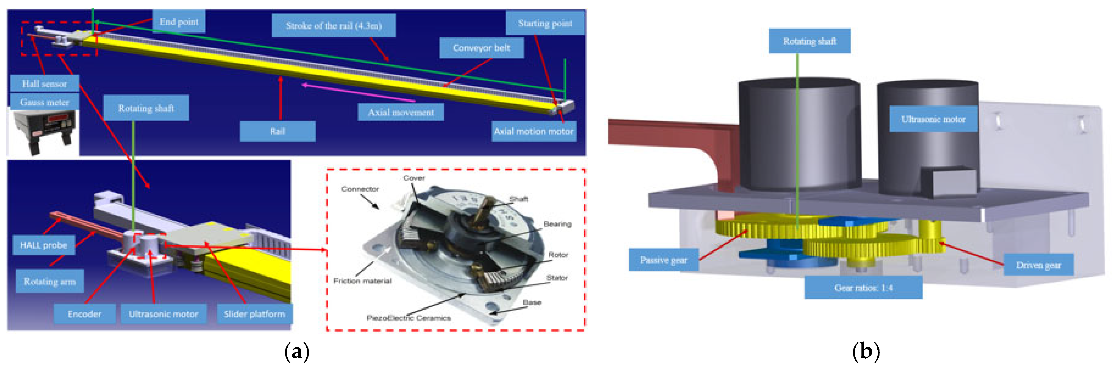
The ultrasonic motor drives the rotating arm and the Hall sensor to move inside the magnet. The ultrasonic motor, which can work under strong magnetic fields, makes it possible to place the platform inside the magnet gap and drive the arm to rotate under a strong magnetic field, radically reducing the size and weight of the test system.
(2)
In the magnet air gap, the rotating motion mechanism is used instead of the traditional horizontal linear motion mechanism, which reduces the height of the test system and makes it possible to use in a smaller magnet gap.
As shown in Figure 2a, a rotating motion mechanism was adopted inside the magnet. The ultrasonic motor and encoder can be placed on the side of the rail and only the rotating arm above the rail, thus reducing the height of the test system. If the rotating motion mechanism is not employed, an additional horizontal sliding rail must be installed above the slider platform for the horizontal linear motion mechanism. The ultrasonic motor, encoder, and measuring rod would then also be installed above the slider platform, increasing the height of the test system.
At the same time, the rotating arm is installed on the slider platform, and the length only needs to cover the width of the good-field region. This reduces the length of the rotating arm so that it can be quickly stabilized after stopping (less than 1 s), which greatly reduces the settling time of the measuring rod and improves the test efficiency. In contrast, in the traditional Hall probe mapping measurement system, the length of the measuring rod often needs to exceed half the length of the magnet, and the wait time is usually more than 20 s.
(3)
The maximum angular resolution of the ultrasonic motor is 360°/2500. As shown in Figure 2b, the angular resolution of the rotating mechanism can be increased to 360°/10,000 by adopting the 1:4 gear set structure. The length of the rotating arm is 280 mm, the Hall sensor is mounted at the end of the rotating arm, and the circumference of the Hall sensor along the axis of rotation is 280 mm × 2π. When the Hall sensor rotates once around the rotating shaft, the circumference can be subdivided into 10,000 parts, and the calculated minimum step distance is 280 mm × 2π/10,000 ≈ 0.176 mm. As a reference point on the arc to be measured, the maximum position error of the Hall sensor from the ideal coordinate on the arc to be measured is ≈0.176 mm/2 < 0.09 mm.

2.2. The Components of the Portable Magnetic Field Mapping Measurement System

The composition of the measuring system is shown in Figure 2a, with the following components:
(1)
The rail, with a translational stroke of 4.3 m when testing the SRing dipole magnet and HFRS warm-ion superconducting dipole magnet, was lengthened to 5.3 m when testing the HFRS anti-irradiation dipole magnets.
(2)
The slider platform was designed to move along the rail and can be equipped with an ultrasonic motor, encoder, and rotating arm on its side.
(3)
The axial motion servo motor and conveyor belt are used to transfer the slider platform to the magnet air gap.
(4)
The ultrasonic motor and the encoder have stable operation under a strong magnetic field (≥7 T).
(5)
The rotating arm has an initial length of 280 mm and can be changed according to the magnet type. A Hall sensor is installed at the end. Driven by an ultrasonic motor, the measuring arm with the Hall sensor moves in an arc in the middle plane of the magnet aperture. With the axial movement of the slider table, the magnetic field distribution in the whole magnet plane can be measured.
(6)
The Group 3 Company’s DTM 151 Gauss meter and MPT 141 Hall probe [15].
(7)
A nuclear magnetic resonance instrument (NMR) [16] is used to check the magnetic field of the Gauss meter before the formal test to ensure the accuracy of the Gauss meter itself and that fixed.

2.3. The Magnetic Field Measurement Method and Coordinate Calculation

The magnetic field measurement uses the traditional point-to-point method. The slider platform and rotating arm are driven to move the Hall sensor to the measured point, and then the Gauss meter and data acquisition instrument are triggered by the encoder to collect the magnetic field and current. The next point is tested until the magnetic field measurement of all points is completed.
In a stationary Cartesian coordinate system, the path of a dipole magnet is a series of parallel arcs with a deflection radius. However, the position coordinates of the measurement system are composed of a linear motion variable ( L i ) in the stationary coordinate system and a rotational angle variable ( θ i ) in the moving coordinate system, moving with the slider platform. Therefore, the arc path coordinates need to be geometrically transformed to the new coordinate system for testing.
The stationary coordinate system was established with the starting position of the rotating shaft as the origin, and the moving coordinate system was established with the real-time position of the rotating shaft as the origin. The axis directions are shown in Figure 3.
The description of the parameters in Figure 3 is shown in Table 1.
The coordinate transformation of the linear motion variable ( L i ) and rotational angle variable ( θ i ) and the coordinates of any point in an arc to be measured are expressed as follows:
L p = R s i n α s i n α i = L i + r c o s θ i
Y p = C R 1 c o s α i = r s i n θ i
Solve the equations of the linear motion variable ( L i ) and rotational angle variable ( θ i ) as shown:
θ i = a r c s i n C R 1 c o s α i r
L i = R s i n α s i n α i r c o s θ i
Variables within the entire measurement plane can be solved using Python 3.12.

3. Results

3.1. The Magnet Parameters and Measurement Requirements for SRing and HFRS Dipole Magnets

The parameters and requirements are shown in Table 2 and Table 3.

3.2. The Measurement of SRing Dipole Magnets

3.2.1. Position Accuracy Test

After the system was built, we used a laser tracker to test and debug the accuracy of the system’s motion position. The position accuracy test was divided into two parts: the linear motion along the rail, and the rotating motion along the ultrasonic motor’s rotating shaft.
When measuring the position accuracy of linear motion along the guide rail, 30 mm was used as the test step, and the total test length was 4320 mm (longer than the test range of the SRing dipole magnet). The test results are shown in Figure 4a. The maximum deviation of a single-step size movement was less than 0.1 mm, the average distance of actual movement was 29.999 mm, the mean deviation was about 0.001 mm, and the root mean square deviation was 0.022 mm. These results were considered to meet our test requirements.
When measuring the rotational accuracy, the angle step was 2°, and the total measurement angle was 90°. The test results are shown in Figure 4b. The results showed that the maximum deviation of a single step size was 0.048°, the average rotation angle was 2.0008°, and the mean deviation was about 0.0002°. These results were also considered to meet the test requirements.

3.2.2. Measurement Uncertainty

(1)
Position uncertainty of the Hall sensor (Lp, Yp)
The position uncertainty of the Hall sensor mainly originates from the linear motion uncertainty of the slider platform along the rail and the rotation uncertainty of the rotating arm. The linear and rotational motions are independent.
A.
Linear motion uncertainty: Includes Type A and Type B uncertainties.
Type A Uncertainty (Repeatability):
Figure 4a shows the step-length measurement results of the slider platform moving along the rail.
For repeated measurements, calculate the arithmetic mean of the measured step-length values:
Z ¯ = 1 n i = 1 n z i = 29.999   m m
Calculate the standard deviation of the step-length measurement s z :
s z = 1 n 1 i = 1 n ( z i z ¯ ) 2 = 0.022   m m
Calculate the standard uncertainty of the step-length mean value:
u Z ¯ = s z n 0.002   m m
Type B Uncertainty:
The API Radian Laser Tracker was used, with a single-point measurement accuracy of 10 µm + 5 µm/m. The measurement distance was about 5 m, and the maximum permissible error (MPE) was ΔTL:
T L = 10   μ m + 5   μ m × 5 = 0.035   μ m
For a uniform distribution, the uncertainty of the Laser Tracker is:
u l a s e r = Δ T L 3 = 0.020   m m
Combined Uncertainty:
The combined standard uncertainty u c,z can be calculated using the following formula:
u c , z = ( u Z ¯ ) 2 + u l a s e r 2 = 0.20   m m
B.
Rotational Motion Uncertainty: Includes Type A and Type B uncertainties.
Type A Uncertainty (Repeatability):
Figure 4b shows the measurement results of the angular step length of the rotational motion. It can be seen that the maximum error in the measurement interval was less than 0.05°.
Calculate the arithmetic mean of the angular measured values:
θ ¯ = 1 n i = 1 n θ i = 20.0001 °
Calculate the standard deviation of a single angular measurement:
s θ = 1 n 1 i = 1 n ( θ i θ ¯ ) 2 = 0.0165 °
Calculate the standard uncertainty of the angular mean value :
u θ ¯ = s θ n 0.0025 °
The length of the rotating arm was 280 mm. Calculate the standard uncertainty of the step-length mean value:
u r o t a t i o n = u θ ¯ π 180 280   m m = 0.012   m m
Type B Uncertainty:
The measurement distance was about 2 m, and the maximum permissible error (MPE) is ΔTR:
T R = 10   μ m + 5   μ m × 2 = 0.02   μ m
For a uniform distribution, the uncertainty of the Laser Tracker is:
u l a s e r = Δ T R 3 = 0.012   m m
Combined Uncertainty:
The combined standard uncertainty uc,R can be calculated using the following formula:
u c , R = ( u r o t a t i o n ) 2 + u l a s e r 2 = 0.017   m m
Combined Standard Uncertainty:
The linear and rotational motions are independent, and the combined standard uncertainty uc can be calculated using the following formula:
u c = ( u c , z ) 2 + u c , R 2 = 0.026   m m
Select a coverage factor k (typically k = 2 for 95% confidence), and the expanded uncertainty is:
U = k u c = 2 0.026 = 0.052   m m
The combined uncertainty of the Hall sensor’s position was 0.052 mm. From the perspective of uncertainty composition, this mainly came from tracker uncertainty. In addition, relative to the measurement length range of a magnet (>4 m), the measurement uncertainty of 0.052 mm is considered acceptable. This conclusion received additional substantiation from the following magnetic field measurement data.
(2)
The uncertainty of the Gauss meter
The uncertainty of the Gauss meter belongs to Type B uncertainty. As can be seen from the Gauss meter’s certification, its accuracy varies with the range as follows:
The accuracy of DTM-151 with MPT-141 probe is: ±0.01% of reading ±0.006% of full-scale max.
The maximum permissible error (MPE) is ΔB:
B = 30000 × 0.00001   G s + 1.66 × 0.00006   G s = 3.996   G s
Calculate the uncertainty:
u G = Δ B 3 = 2.31   G s
Select a coverage factor k (typically k = 2 for 95% confidence), and the expanded uncertainty is:
U = k u G = 2 2.31 = 4.62   G s

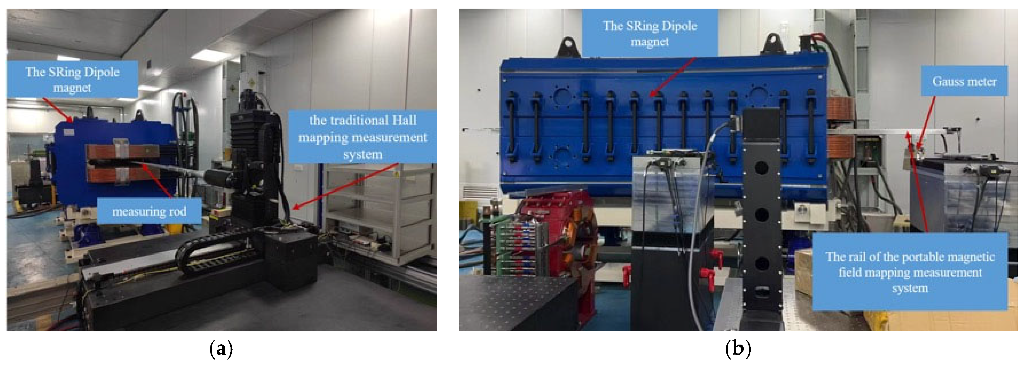
3.2.3. The Comparison Between the Traditional and the Portable Magnetic Field Mapping Measuring System to Measure the Prototype SRing Dipole Magnet

After verifying the system position accuracy, the magnetic field of the SRing dipole magnet was measured to verify the accuracy and efficiency of the system.
Figure 5a shows the SRing dipole magnet measurement image using the traditional Hall mapping measurement system, and Figure 5b shows the measurement image using the portable magnetic field mapping measurement system. The same Hall sensor was used for both measurements to minimize the contrast variables.
Figure 6 shows the comparison results of the SRing dipole magnet integral field homogeneity measured by the two systems, and the trend of the magnetic field homogeneity distribution was consistent. The stability and reliability of the traditional Hall mapping measurement system have been recognized by several years of long-term testing. Therefore, the portable magnetic field mapping measurement system has been indirectly verified to be reliable. The difference in measurement results between the two magnetic field mapping measurement systems was small, mainly due to the alignments and random errors.
It is worth emphasizing that the time step of the traditional magnetic field measurement system is about 20 s per point, and the new system only takes about 1.6 s per point. Therefore, the test efficiency was improved by more than 10 times.
In addition, during test preparation, the portable magnetic field mapping measurement system can save more time and cost than the traditional Hall mapping measurement system. Testing with the portable magnetic field mapping measurement system requires only one removal and assembly of the magnet, cooling water connection, circuit connection, magnet calibration, and alignment of the test system. In contrast, the traditional Hall mapping measurement system requires additional time to align the magnet plane parallel to the measurement plane. In particular, the traditional Hall mapping measurement system can only complete the half-size magnetic field test in a single measurement, and another half-size magnetic field test requires the magnet to be lifted and reversed again. Because the weight of the large dipole magnet exceeds the crane’s rated load, the magnet’s secondary lifting needs to be disassembled and then assembled, which adds a lot of additional time and cost. Especially for superconducting magnets, additional cooling time and costs are required.

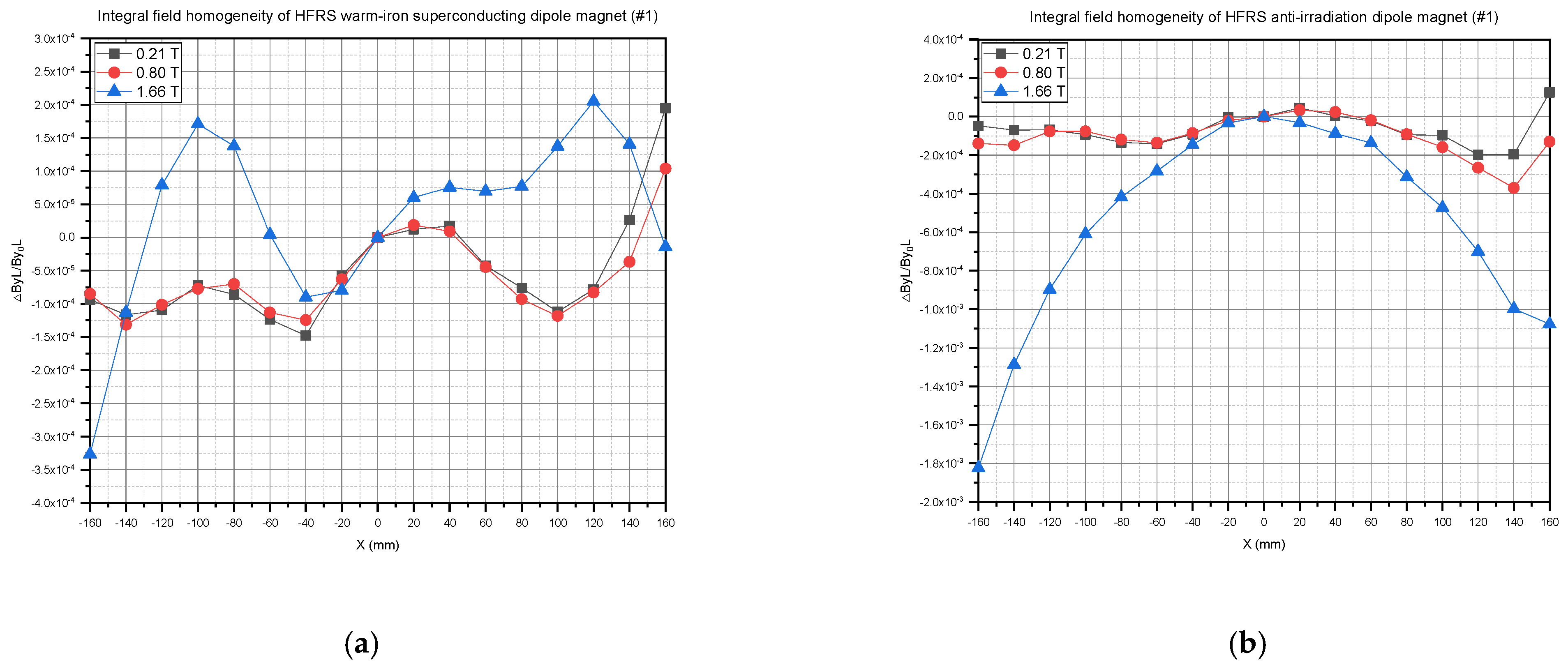
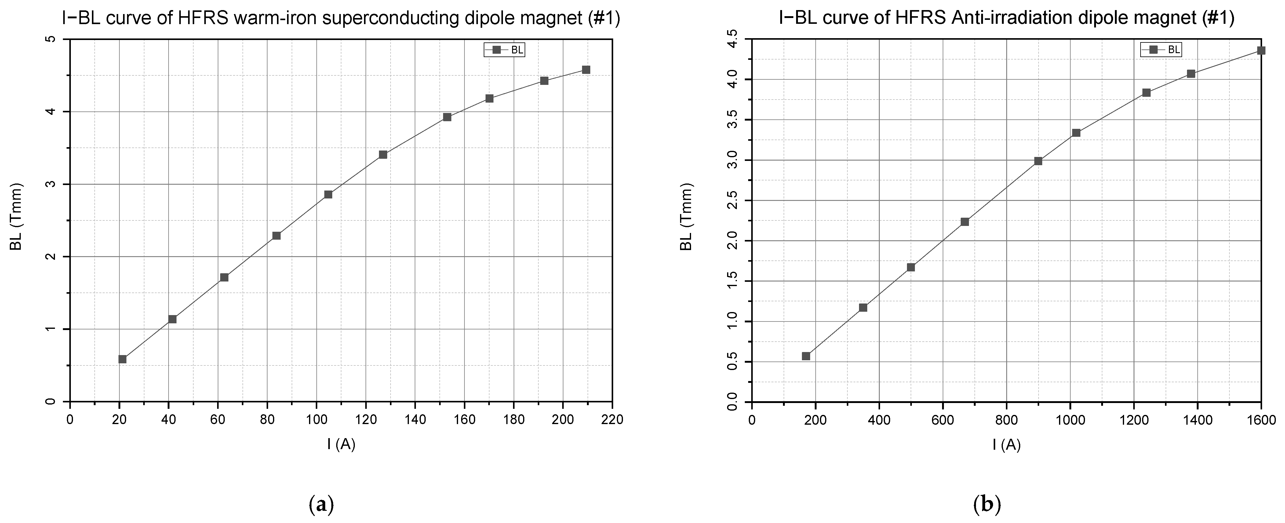
3.3. The Magnetic Field Batch Measurement of the HFRS Warm-Iron Superconducting Dipole Magnets and the HFRS Anti-Irradiation Dipole Magnets

Based on the measurement and verification of the magnetic field of the SRing dipole magnet, the magnetic field distribution and integral excitation curve measurements of 11 HFRS warm-iron superconducting dipole magnets and 3 anti-irradiation dipole magnets were carried out and completed. The measurement results of the two kinds of magnet prototypes are as follows:
Figure 7a shows the HFRS superconducting dipole magnet measurement, and Figure 7b shows the HFRS anti-irradiation dipole magnet measurement. Each magnet needs about 3 days to assemble before the measurement, and the superconducting magnet needs an additional 3 days of cooling preparation. However, the magnetic field measurements only take one day.
Figure 8a shows the integral field homogeneity of one of the HFRS warm-iron superconducting dipole magnets, and Figure 8b shows the integral field homogeneity of one of the HFRS anti-irradiation dipole magnets. The uniformity of the magnetic field met the physical requirements, and the accuracy of the test system was again verified.
Figure 9a shows the I–BL curve of one of the HFRS warm-iron superconducting dipole magnets, and Figure 9b shows the I–BL curve of one of the HFRS anti-irradiation dipole magnets.
So far, all 11 warm-iron superconducting dipole magnets and 3 anti-irradiation dipole magnets of HFRS have been tested, and the test results of all magnets met the design requirements. The stability of the system was verified very well.

4. Discussion

In this paper, a portable magnetic field mapping measurement system was developed to measure the large dipole magnets in the HIAF. The test results demonstrated that the new system exhibits excellent measurement accuracy and high testing efficiency, and its portability makes it universally applicable for measuring large dipole magnets, especially large superconducting dipole magnets. The high efficiency and portability were attributed to its ingenious mechanical design and the application of ultrasonic motors. Compared with traditional Hall mapping measurement systems, the new system’s testing accuracy was comparable, with a more than tenfold improvement in measurement efficiency, and it has significant advantages in mobility. The system has broad application prospects in magnetic field mapping measurement for accelerator magnets, especially for large superconducting magnets. The limitation lies in its linear rail, which is not suitable for magnets with large deflection angles and a small aperture. Future research could focus on developing a curved rail test system.

Author Contributions

Conceptualization, X.Z. and Q.Y.; Methodology, X.Z. and Z.W.; Software, L.J., Z.W. and J.Y.; Validation, X.Z. and Q.Y.; Formal analysis, X.Z., Z.W., L.J. and L.Z.; Investigation, Z.W., L.J., X.O. and Y.T.; Resources, D.N., Y.C., W.D. and B.W.; Data curation, Z.W., L.J., L.Z. and X.Z.; Writing—original draft preparation, X.Z.; Writing—review and editing, X.Z. and Q.Y.; Visualization, X.Z.; Supervision, Q.Y.; Project administration, X.Z. and Q.Y.; Funding acquisition, Q.Y. and G.L. All authors have read and agreed to the published version of the manuscript.

Funding

This research was funded by the Lanzhou Science and Technology Project (grant number E139973SQ0) and the High Intensity Heavy-Ion Accelerator Facility (HIAF) approved by the National Development and Reform Commission of China (grant number 2017-000052-73-01-002107). The APC was funded by the Lanzhou Science and Technology Project (grant number E139973SQ0).

Data Availability Statement

The data supporting the findings of this study are included within the article.

Acknowledgments

The authors wish to thank the technical team of Hefei Micro Precision Control Instrument Technology Co., Ltd. for their help in the process of developing the test system.

Conflicts of Interest

The authors declare no conflicts of interest. The funders participated in the project management.

References

  1. Zhang, X.; Ma, L.Z.; Wu, W.; Yang, W.J.; Zhao, L.X.; Yang, J.; Lv, M.B.; Mei, E.M.; Chen, Y.Q.; Zhang, J.J.; et al. Optimization design and test of the Booster Ring dipole magnet in HIAF. J. Instrum. 2022, 17, P03024. [Google Scholar] [CrossRef]
  2. Yang, J.C.; Xia, J.W.; Xiao, G.Q.; Xu, H.S.; Zhao, H.W.; Zhou, X.H.; Ma, X.W.; He, Y.; Ma, L.Z.; Gao, D.Q.; et al. High Intensity heavy ion Accelerator Facility (HIAF) in China. Nucl. Instrum. Methods Phys. Res. Sect. B Beam Interact. Mater. At. 2013, 317, 263–265. [Google Scholar] [CrossRef]
  3. Ma, X.; Wen, W.Q.; Zhang, S.F.; Yu, D.Y.; Cheng, R.; Yang, J.; Huang, Z.K.; Wang, H.B.; Zhu, X.L.; Cai, X.; et al. HIAF: New opportunities for atomic physics with highly charged heavy ions. Nucl. Instrum. Methods Phys. Res. Sect. B Beam Interact. Mater. At. 2017, 408, 169–173. [Google Scholar] [CrossRef]
  4. Zhou, X.; Yang, J. Status of the high-intensity heavy-ion accelerator facility in China. AAPPS Bull. 2022, 32, 35. [Google Scholar] [CrossRef]
  5. Wu, B.; Yang, J.C.; Xia, J.W.; Yan, X.L.; Hu, X.J.; Mao, L.J.; Sheng, L.N.; Wu, J.X.; Yin, D.Y.; Chai, W.P.; et al. The design of the Spectrometer Ring at the HIAF. Nucl. Instrum. Methods Phys. Res. Sect. A Accel. Spectrometers Detect. Assoc. Equip. 2017, 881, 27–35. [Google Scholar] [CrossRef]
  6. Sheng, L.N.; Zhang, X.H.; Zhang, J.Q.; Yang, J.C.; Sun, Z.Y.; Mao, L.J.; Wu, W.; Yin, D.Y.; Ruan, S.; Shen, G.D.; et al. Ion-optical design of High energy Fragment Separator (HFRS) at HIAF. Nucl. Instrum. Methods Phys. Res. Sect. B Beam Interact. Mater. At. 2020, 469, 1–9. [Google Scholar] [CrossRef]
  7. Wu, B.; You, W.; Ou, X.; Tong, Y.; Ren, W.; Cheng, Y.; Zhang, X.; Jin, L.; Ni, D.; Mei, E.; et al. Mechanical Design, Construction and Testing of the Superferric Dipoles for the High Energy Fragment Separator of the HIAF. IEEE Trans. Appl. Supercond. 2024, 34, 5. [Google Scholar] [CrossRef]
  8. Moritz, G. Mechanical Equipment; CERN Accelerator School, Europa Palapa Hotel: Anacapri, Italy, 1997; pp. 251–257. [Google Scholar]
  9. He, Y. Magnetic Measurement System for CSR and Its Applications; University of Chinese Academy of Sciences: Beijing, China, 2003. [Google Scholar]
  10. Samaille, L.; Le Bec, G.; Versteegen, R. Update of the magnetic measurement benches of the ESRF. In Proceedings of the 23rd International Magnetic Measurement Workshop, Bad Zurzach, Switzerland, 6–11 October 2024. [Google Scholar]
  11. Zhang, X.; Jin, L. Magnetic Field Measurement System of the BRing Fast Ramping Dipole Magnet in HIAF. Nucl. Phys. Rev. 2022, 39, 470–475. [Google Scholar]
  12. Golluccio, G.; Giloteaux, D.; Dunkel, O.; Caltabiano, D.; Schnizer, P.; Fiscarelli, L.; Deferne, G.; Buzio, M.; Petrone, C.; Russenschuck, S. Instruments and methods for the magnetic measurement of the super-FRS magnets. In Proceedings of the IPAC2016, Busan, Republic of Korea, 8–13 May 2016. [Google Scholar]
  13. Hetzel, J.H.; Böker, J.; Bechstedt, U.; Quilitzsch, S.; Engin, I.; Ehrlich, C.; Bationo, B.; Tripathi, P.; Soltner, H.; Keller, P.; et al. Development of a Field Mapper for the Determination of the Multipole Components of the Curved HESR Dipole Magnets. IEEE Trans. Appl. Supercond. 2018, 28, 1–4. [Google Scholar] [CrossRef]
  14. CSX52S3-40. Available online: https://www.scnuaa.com/product/64.html (accessed on 12 February 2025).
  15. High Precision Teslameter/Gaussmeter. Available online: https://www.group3technology.com/dtm-151-product-detail (accessed on 12 February 2025).
  16. NMR Precision Teslameter PT2026. Available online: https://www.metrolab.com/products/nmr-precision-teslameter-pt2026 (accessed on 12 February 2025).
Figure 1. The layout of the HIAF.
Metrology 05 00022 g001
Figure 2. (a) The components of the measurement system. (b) The 1:4 dual-gear structure.
Metrology 05 00022 g002
Figure 3. The coordinate conversion diagram.
Metrology 05 00022 g003
Figure 4. (a) The accuracy test of step size in linear motion along the rail. (b) The accuracy test of the angular step in rotating motion.
Metrology 05 00022 g004
Figure 5. (a) SRing dipole magnet test by the traditional Hall mapping measurement system. (b) SRing dipole magnet test by the portable magnetic field mapping measurement system.
Metrology 05 00022 g005
Figure 6. The comparison of the integrated field homogeneity of the SRing dipole magnet.
Metrology 05 00022 g006
Figure 7. (a) Test of HFRS warm-iron superconducting dipole magnet. (b) Test of HFRS anti-irradiation dipole magnet.
Metrology 05 00022 g007
Figure 8. (a) The integral field homogeneity of the HFRS superconducting magnet (#1). (b) The integral field homogeneity of the HFRS anti-irradiation dipole magnet (#1).
Metrology 05 00022 g008
Figure 9. (a) The I–BL curve of the HFRS superconducting magnet (#1). (b) The I–BL curve of the HFRS anti-irradiation dipole magnet (#1).
Metrology 05 00022 g009
Table 1. Description of the parameters in Figure 3.
ParametersDescription
L i The linear motion variable
(the length between the rotating shaft and the origin of the stationary coordinate system)
θ i The rotational angle variable
RThe deflection radius of the dipole magnet
rThe radius of the rotating arm
(the length between the rotating shaft and the Hall sensor)
LpThe length between the Hall sensor and the origin of the stationary coordinate system
OMThe center of the arc to be measured
CThe vertex of the arc to be measured
PReal-time position of the Hall sensor
OThe origin of the stationary coordinate system
(starting position of rotating shaft)
O′The origin of the moving coordinate system
(real-time position of rotating shaft)
α i C O M P
α C O M O
Table 2. The magnet parameters.
ParametersSRing Dipole MagnetsHFRS Warm-Ion Superconducting Dipole MagnetsHFRS Anti-Irradiation Dipole MagnetsUnit
Number20113/
Range of magnetic field0.21–1.660.22–1.60.21–1.6T
Reference magnetic field1.10.830.83T
Gap104140206mm
Good-field region (H × V)236 × 80 (0.21–0.84 T)
318 × 80 (0.84–1.39 T)
236 × 80 (1.39–1.66 T)
320 × 124320 × 180mm
Bending radius9.515.715.7m
Deflection angle181010°
Effective length2984.52740.22740.2mm
Edge angle000°
Integral field homogeneity (△ByL/ByL0)±3 × 10−4 (318 × 80 at 1.10 T)
±5 × 10⁻⁴ (220 × 80 at 1.66 T)
±3 × 10⁻⁴ (240 × 80 at 0.21 T)
±3 × 10⁻⁴ (0.2~1.2 T)±3 × 10⁻⁴ (0.83 T)
±8 × 10⁻⁴ (1.60 T)
/
Maximum current17802101600A
weight45,00052,00081,000kg
Table 3. The magnetic field distribution measurement requirement.
Items SRing Dipole Magnets HFRS Warm-Ion Superconducting Dipole Magnets HFRS Anti-Irradiation Dipole Magnets
Number1113
Reference magnetic field0.21 T, 1.1 T, 1.66 T0.22 T, 0.83 T, 1.6 T0.21 T, 0.83 T, 1.6 T
Disclaimer/Publisher’s Note: The statements, opinions and data contained in all publications are solely those of the individual author(s) and contributor(s) and not of MDPI and/or the editor(s). MDPI and/or the editor(s) disclaim responsibility for any injury to people or property resulting from any ideas, methods, instructions or products referred to in the content.

