Review

High-Speed 3D Vision Based on Structured Light Methods

Research Institute for Science and Technology, Tokyo University of Science, 6-3-1 Niijuku, Katsushika-ku, Tokyo 125-8585, Japan
*
Author to whom correspondence should be addressed.
Metrology 2025, 5(2), 24; https://doi.org/10.3390/metrology5020024
Submission received: 23 December 2024 / Revised: 18 March 2025 / Accepted: 10 April 2025 / Published: 15 April 2025

Abstract

:
Three-dimensional measurement technologies based on computer vision have been developed with the aim of achieving perceptual speeds equivalent to humans (30 fps). However, in a highly mechanized society, there is no need for computers and robots to work slowly to match the speed of human perception. From this kind of circumstance, high-speed 3D vision with speeds far beyond that of humans, such as 1000 fps, has emerged. High-speed 3D measurement has great applicability not only for accurately recognizing a moving and deforming target but also for enabling real-time feedback, such as manipulation of the dynamic targets based on the measurement. In order to accelerate 3D vision and control the dynamic targets in real time, high-speed vision devices and high-speed image processing algorithms are essential. In this review, we revisit the basic strategy, triangulation as a suitable measurement principle for high-speed 3D vision, and introduce state-of-the-art 3D measurement methods based on high-speed vision devices and high-speed image processing utilizing structured light patterns. In addition, we introduce recent applications using high-speed 3D measurement and show that high-speed 3D measurement is one of the key technologies for real-time feedback in various fields such as robotics, mobility, security, interface, and XR.

1. Introduction

Non-contact 3D measurement technology, which uses light to acquire the three-dimensional shape of an object, is used in a wide range of fields such as inspection and survey [1,2,3]. Three-dimensional measurement technology has been developed mainly for stationary objects and improved to achieve high accuracy, expand the measurement range, and handle various surface conditions and scales [4,5,6,7,8,9,10]. In recent years, high-speed 3D measurement technology has been developed to acquire geometry with a high temporal resolution such as 1000 fps, which far exceeds the speed of human perception—video rate (30 fps). These technologies have been utilized in systems that capture and immediately respond to dynamic objects with motion and deformation in fields such as robotics, mobility, security, interfaces, and XR including augmented reality (AR) and virtual reality (VR) [11,12,13]. In 3D measurement of such moving objects, the measurement device itself must be fast enough to respond to the speed of the target, and the measurement method must be applicable to dynamic objects. On the other hand, most conventional measurement methods assume a stationary object and calculate the 3D position using multiple sample values acquired from the sensor in a time division manner, which may cause measurement errors or measurement failures when applied to dynamic objects [14,15]. Therefore, accurate measurement of time-varying objects requires advanced measurement methods that extract 3D information from as few samples as possible. In addition, in order to immediately feedback the obtained 3D information to the system and manipulate the object appropriately, the amount of computation from sampling to calculation of 3D information must be small and with low latency.
In recent years, the mainstream of 3D measurement methods for dynamic objects has been the time-of-flight (ToF) method [16] and triangulation using structured light patterns [17]. However, the direct ToF method, which directly measures the time it takes for light to reflect off an object and return, requires a high-precision time measurement at each measurement point, and so it is difficult to achieve both high accuracy and high resolution [18]. The indirect ToF method, which uses modulation and phase difference to back-calculate the distance to the target, requires multiple samplings for measurement, and the frame rate of the measurement device itself is low, so there are still many issues to be solved in order to achieve high-speed measurement [19,20]. On the other hand, a structured light method using a camera and pattern projector, as shown in Figure 1, has the potential to achieve high-speed measurement based on high-speed camera technologies that enable measurement at a high frame rate. Additionally, the structured light method can reduce the number of samples (number of frames) required for the measurement and the amount of computation by improving image processing and the projection pattern. In this paper, we focus on high-speed 3D measurement realized by high-speed image processing within the framework of the structured light method and review studies to date [21]. In the following chapters, we first introduce high-speed vision devices that support high-speed 3D measurement technologies and then outline the features, performance, and applications of the high-speed 3D measurement methods that have been studied in recent years.

2. High-Speed Vision Devices

The frame rate of a typical camera is called the video rate, which is about 30 fps. This value is set based on human perception and is sufficient to perceive the switching of still images as continuous motion (apparent motion). However, in machine vision, where images are analyzed by a computer, the frame rate needs not to be based on humans but should be set to cover the dynamics of the target object and maximize system performance.
Against this background, 3D measurement using high-speed cameras with frame rates of 1000 fps has been investigated. However, even if the image capture is fast, if the image processing, actuators, and display in the subsequent stages are slow, they become bottlenecks, and the effect of fast image capture on system performance is limited. Therefore, we have developed a vision chip that performs high-speed image capture at 1000 fps and programmable parallel image processing on the image sensor [22], a saccade mirror that uses galvanometer mirrors for high-speed gaze direction control [23,24], a liquid lens that controls the focus position at high speed [25], and a high-speed projector that achieves projection at 1000 fps by coordinately controlling a digital mirror device (DMD) and LEDs [26,27,28]. In particular, vision chips and high-speed projectors play a significant role in high-speed 3D measurement. In 3D measurement using the structured light method, image processing must be applied to the captured image to obtain the final result, a 3D point cloud. Since this type of image processing often involves parallelizable processes for each 3D point, devices that can perform parallel image processing at the edge without involving data transfer, such as vision chips, contribute to faster and lower-latency 3D measurements. In addition, in multi-shot measurement methods using multiple structured light patterns, high-speed projectors can perform multiple sampling in a flash with high-speed cameras, and contribute to faster 3D measurement.
In the following sections, we will briefly introduce conventional structured light patterns for stationary targets to understand advanced methods, and then introduce the high-speed 3D measurement methods using structured light patterns.

3. Conventional Structured Light Patterns

This section outlines conventional structured light methods for stationary objects [17] and checks the number of measurement frames that each method assumes to derive a 3D point cloud. As shown in Figure 1, the structured light method requires image processing to obtain the coordinates of a point on the projected image in order to determine the 3D position of the point on the image. However, as shown in Figure 1, it is not necessary to obtain the two-dimensional position on the projected image, and it is sufficient to determine the coordinates in the direction of disparity between the camera and the projector as information for triangulation. In this section, we assume that the camera and projector are aligned horizontally and that an image with a resolution of N pixels is projected from the projector in the horizontal direction without loss of generality. Then, we consider the problem of determining the horizontal coordinates of a point on the projected image corresponding to a point on the captured image (hereinafter called “phase”).
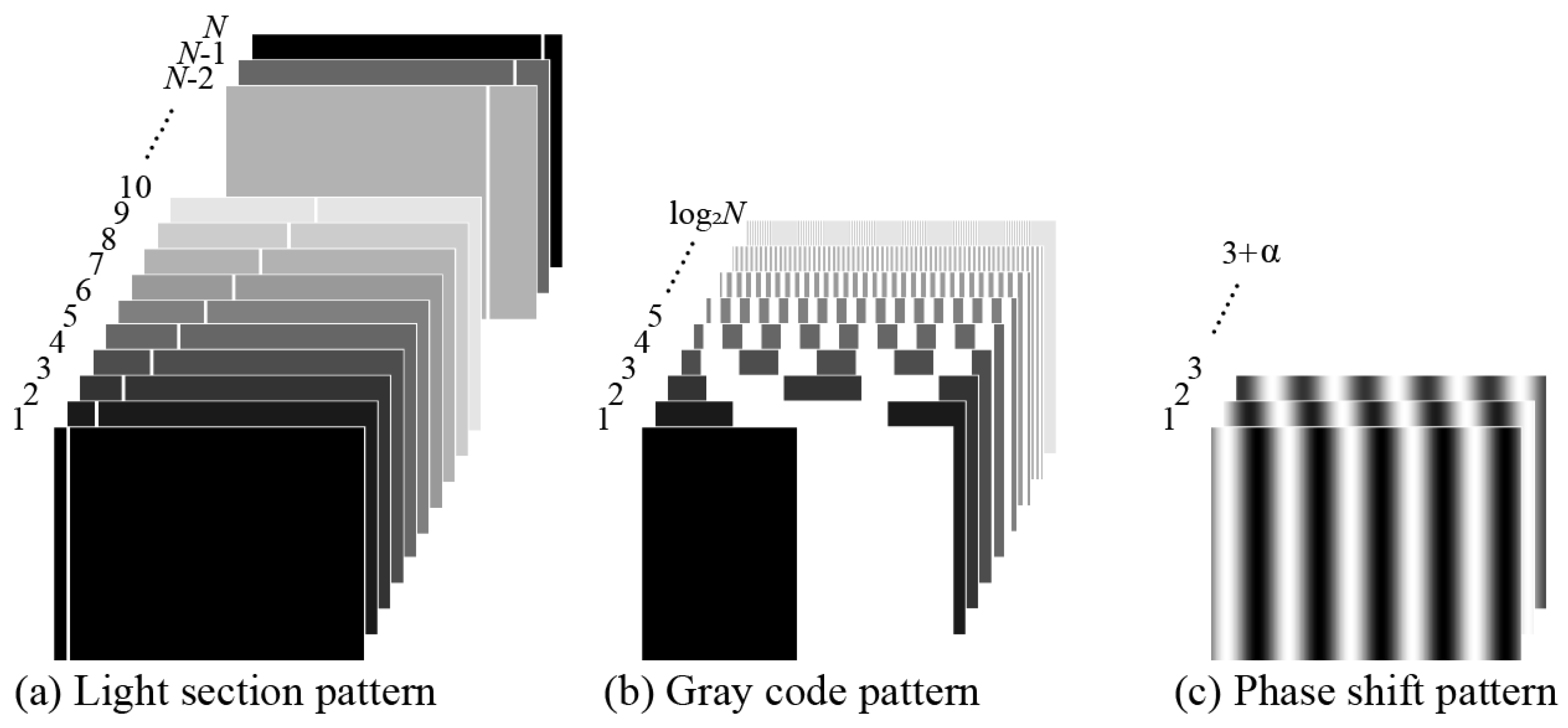
In the light section method [29], this problem is viewed as a problem of finding a point on the image corresponding to a fixed phase. That is, the area corresponding to a certain phase is projected as a bright line, as shown in Figure 2a, and the correspondence is obtained by finding the coordinates of a group of bright points on the image. The light section method completes the measurement in a single frame, but since only the points on the bright lines are measured in a single frame, N frames are required to measure N phases in the simplest pattern using a single bright line. Therefore, the light section method is a robust and accurate method for 3D measurement, but it is a time-consuming method.
The Gray code method [30], in which the phase is described as a discrete binary value, can measure N phases in log 2 N frames by discriminating the phase of each point in the image with a binary pattern sequence using Gray codes, as shown in Figure 2b. The Gray code method reduces the number of frames required for measurement compared to the light section method, but requires a high-resolution projector for high precision because the phase is a discrete value.
The phase-shift method [31,32] assumes the phase to be a continuous value and calculates the phase of each point in the image from the luminance of the sinusoidal pattern sequence as shown in Figure 2c, thereby realizing 3D measurement in at least three frames. In principle, the phase-shift method can perform measurement in three frames regardless of N. However, in order to perform highly accurate measurements with images of limited bit depth, an operation called phase unwrapping is required [33]. In the phase unwrapping, multiple cycles of sinusoidal patterns are projected and their absolute phases are determined by relative phases and additional information. Therefore, in practical applications, the measurement is often performed by adding frames necessary for phase unwrapping, resulting in the measurement of 4 or more frames [34,35,36].
As described above, the number of frames required for the measurement has been reduced in the development of structured light methods to date. However, a faster and lower latency method is desirable for the measurement of dynamic objects. In the following sections, we review the high-speed 3D measurement methods that have been developed for dynamic objects.

4. High-Speed 3D Measurement

4.1. Multi-Shot Methods

Time-encoded structured light methods, which require multiple frames per measurement, need to reduce both the exposure time per frame and the number of required frames for the measurement of dynamic objects. In particular, a faster device is radical to reduce the exposure time per frame. Therefore, a system employing a high-speed camera and a high-speed projector is used for high-speed 3D measurements [37,38,39,40,41]. On the other hand, various approaches to radically reduce the number of frames have been proposed to achieve phase unwrapping without increasing the number of projections.
For example, a method that embeds a binary pattern of Gray code in a sinusoidal pattern has been proposed [35]. In this method, the Gray code is embedded in 1 bit of the projected 8-bit image and used for phase unwrapping. The remaining 7 bits are used for the eight-period sinusoidal pattern, and each pattern is captured by two coaxially positioned cameras with different exposure times and timing. This setup allows both period information from the Gray code and relative phase information from the phase-shift method to be acquired simultaneously, and phase unwrapping is achieved with only three frames of imaging. With this system, real-time 3D measurement of dynamic objects is achieved at 500 fps, and the paper reports that the phase unwrapping was performed offline and took about 2.5 ms. The average error of 3D measurement is 1 mm or less.
In contrast, an order-structured phase-shifting method has been proposed that can be realized using only a single camera while fully utilizing 8 bit depth for sinusoidal patterns [36]. This method uses a pattern with a structure in which the projection order of a multi-period sinusoidal pattern is rearranged by period. As a result, the phase unwrapping problem is attributed to the problem of finding the pattern order, and the phase unwrapping is realized only by comparing the luminance values at each pixel. With this approach, 3D measurements can be performed in 3–4 frames, and even with the actual system, real-time measurements of moving objects at 500 fps are achieved with the pixel-wise resolution of the camera with the processing time of 1.05 ms.
As mentioned above, these methods achieve 500 fps in real systems, but in principle, this frame rate can be further increased, primarily through faster pattern projection. Generally, what determines the frame rate of a projector is the modulation speed of the spatial light modulator (DMD, LCOS, etc.), and the high-speed projectors mentioned above achieved faster projection by modulating a light source (LED, laser, etc.) with a higher modulation speed in conjunction with the spatial light modulator. In this case, the modulation speed of the light source determines the frame rate instead, but a study has reported that even higher speeds can be achieved by parallelizing the devices [42]. Thus, the speed of multi-shot methods is getting higher and higher thanks to the development of high-speed projectors. On the other hand, under the same frame rate, multi-shot methods that require multiple frames for measurement have the problem that the measurement accuracy of dynamic objects is inferior to one-shot methods that require only a single frame because the object moves during the measurement, and in some cases, the multi-shot measurement itself can be numerically unfeasible [14,15].

4.2. One-Shot Methods

Space-encoded structured light methods, which are spatially structured and can measure a 3D point cloud at each frame, can minimize the effects of dynamic object motion.
Random dot patterns are typical space-encoded structured light patterns [43,44]. In this method, a pattern of randomly arranged dots is projected, and the phase is determined by calculating the correlation between the projected image and the captured image. Although this method allows relatively dense measurement in a single shot and is widely used, it is not easy to realize high-speed measurement such as several hundred fps, which is the focus of this paper because it requires scanning while calculating the correlation of 2D images to obtain a 3D point cloud, which is computationally expensive.
On the other hand, regularly arranged dots are used in a multi-spot pattern as a simple space-encoded structured light pattern, and a tracking-based method using the multi-spot pattern has realized high-speed 3D measurement [45]. In this method, the multi-spot pattern consists of an array of spots, and each spot is distinguished by tracking. The method achieves high speed by restricting the image processing area only to the vicinity of the spots in the previous frame. While real-time measurement with a throughput of 955 fps, latency of 4.5 ms and about the order of millimeter accuracy is achieved, there are limitations in the working distance, object speed, and spot layout density for robust tracking.
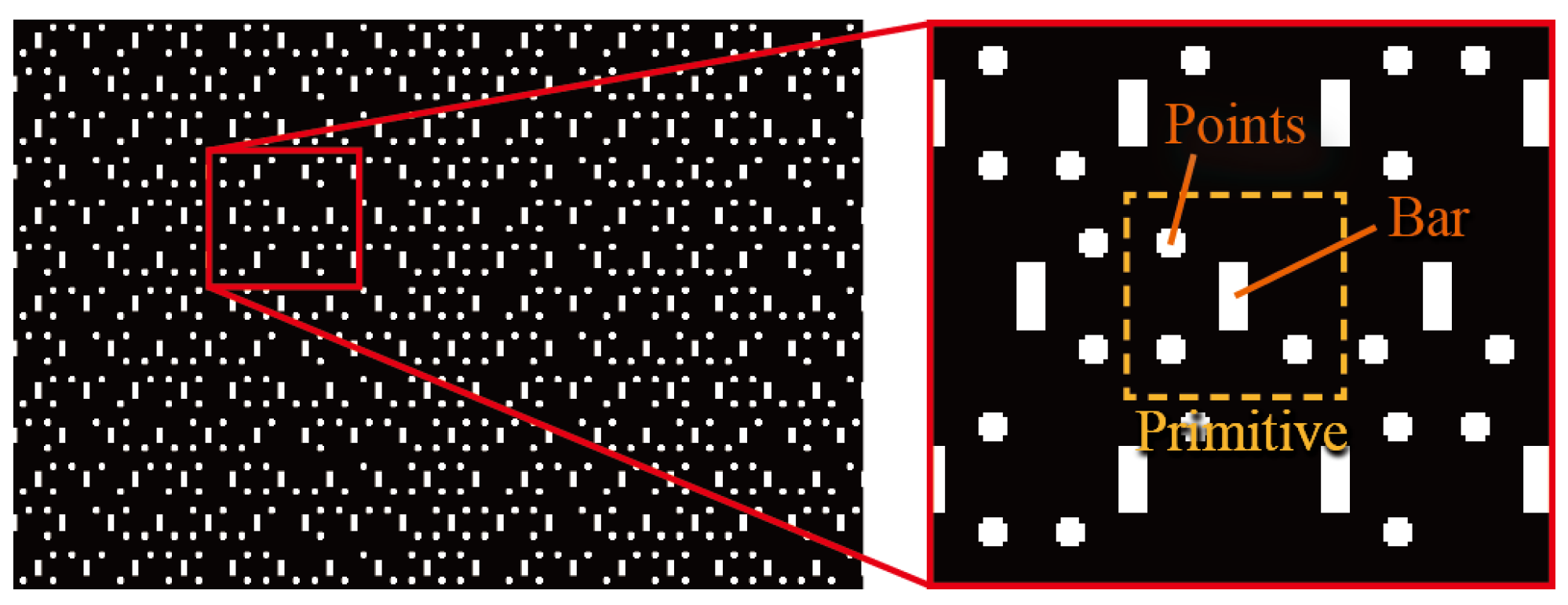
In contrast, a pattern called a segmented pattern, as shown in Figure 3, which has independently identifiable primitives even with a single frame, has been proposed [46]. The method using the segmented pattern achieves an efficient corresponding point search even with the simple pattern by the three-viewpoint geometric structure between the projector and the two cameras. The three-viewpoint epipolar constraints can narrow the search area more than two-viewpoint stereo setup [47,48], and contributes to the speedup of the measurement. Additionally, the hierarchical structure of the bar and points reduces the amount of computation to identify the phase. As a result, the system achieves a computation time of about 2 ms and robustly realizes real-time 3D measurement at 500 fps with 0.8 mm mean error at 450 mm distance. However, optimization of pattern density with respect to image size has not been addressed.
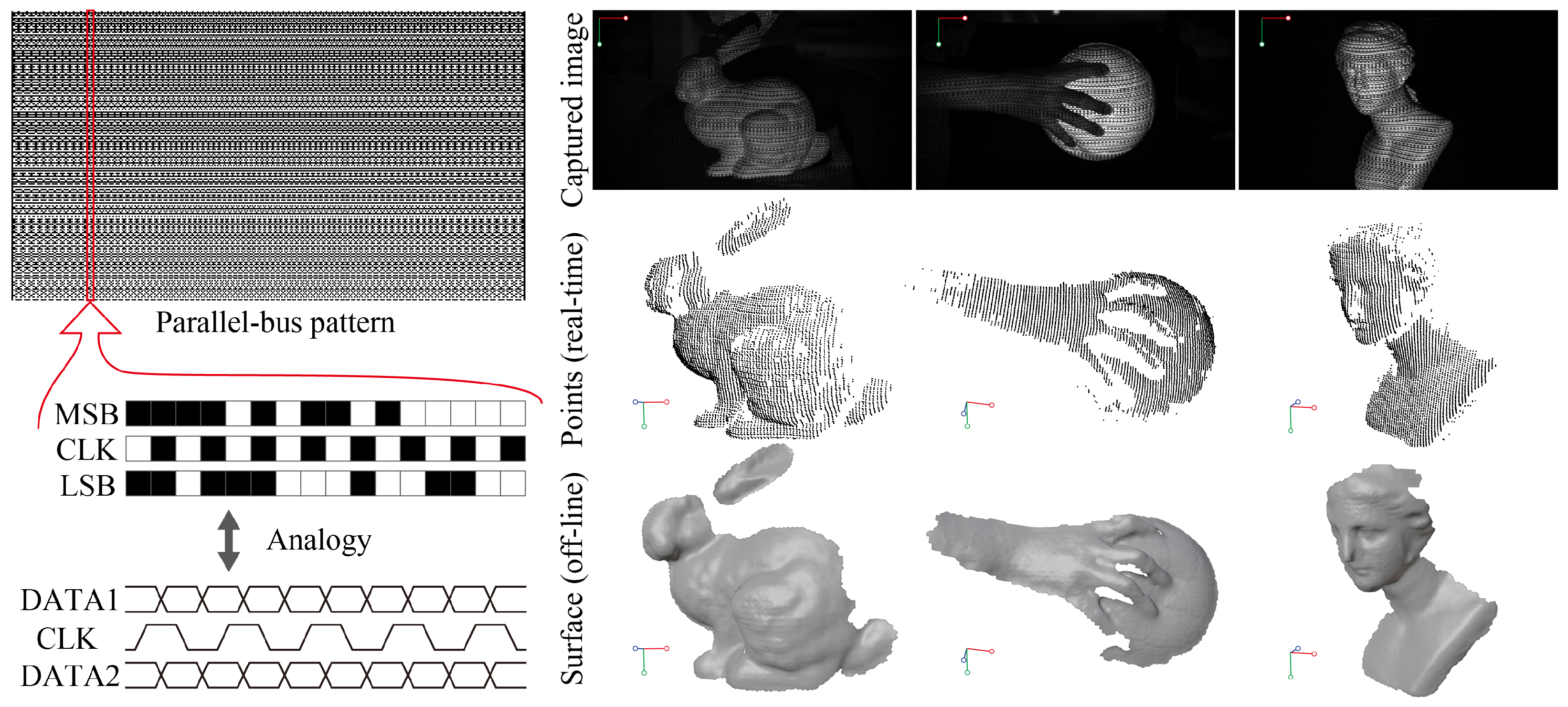
In contrast, a space-encoded pattern called a parallel-bus pattern, as shown in Figure 4, has been proposed to increase measurement density while maintaining the measurement speed [49]. The parallel-bus pattern utilizes the fact that the epipolar lines, i.e., an array of pixels containing phase information, is parallel to a column in the image when the camera and projector are physically arranged in parallel [48], enabling fast and efficient reading of phase information by sequential memory access. The space-encoded pattern incorporates a structure of parallel bus communication based on the analogy between the structured light method and digital communication, and incorporates a regularly switching clock signal and a pseudo-random array of De Bruijn torus [50,51] to speed up phase calculation and optimize measurement density. As a result, an experimental system that measures 26,713 points from a single frame with a computation time of 0.336 ms and 0.838 mm accuracy was realized.

5. Applications of High-Speed 3D Measurement

5.1. High-Speed Measurement and Integration of Depth and Normal

In high-speed 3D measurement, the resolution is sometimes sacrificed in order to prioritize the speed. In particular, in the case of space-encoded patterns introduced in the previous section, it is not easy to realize pixelwise measurement because the phase information is spatially embedded to perform 3D measurement in a single frame.
On the other hand, considering the spatial frequency characteristics of the measurement, measuring the spatial derivative, i.e., tangent plane or surface normal is more efficient to obtain more accurate high-frequency components of the 3D shape than measuring the depth [52]. Therefore, some methods have been proposed to simultaneously measure the low-resolution depth [46] and high-resolution surface normals [13] and to integrate this information to realize high-speed, high-resolution, and high-precision 3D measurements [53]. In this research, the surface normals are obtained in the time of one frame by a wavelength-division photometric stereo method, and pixelwise accurate 3D measurements is calculated as shown in Figure 5. Figure 5b,c shows the 3D point clouds of the front and back surfaces of a moving object obtained by real-time integration, and Figure 5d shows the 3D surface recovered from the point cloud of the back surface. In this study, an algorithm using block parallelization is proposed for high-speed integration of 3D positions and normals that have complementary spatial frequency characteristics in terms of accuracy, achieving high-resolution 3D measurement and integration at 400 fps.

5.2. Three-Dimensional Motion Estimation and Reconstruction

High-speed 3D measurement allows 3D point clouds to be acquired in short time intervals. A fast motion estimation method that takes advantage of this has been proposed [54]. This method focuses on the fact that when the time interval is short enough, the amount of movement between the measured 3D point clouds becomes small. The method used under general conditions where the amount of movement is large is computationally expensive in terms of searching for corresponding points and iterative processing, but this method assumes that the amount of movement is small enough to allow significant simplification of the processing. This method achieves rigid-body motion estimation in less than 1 ms without sacrificing high accuracy compared with a general ICP algorithm [55]. Furthermore, by combining the motion information with point clouds obtained from high-speed 3D measurements, shape reconstruction at 1000 fps is also achieved [56].

5.3. Application in Robotics and XR

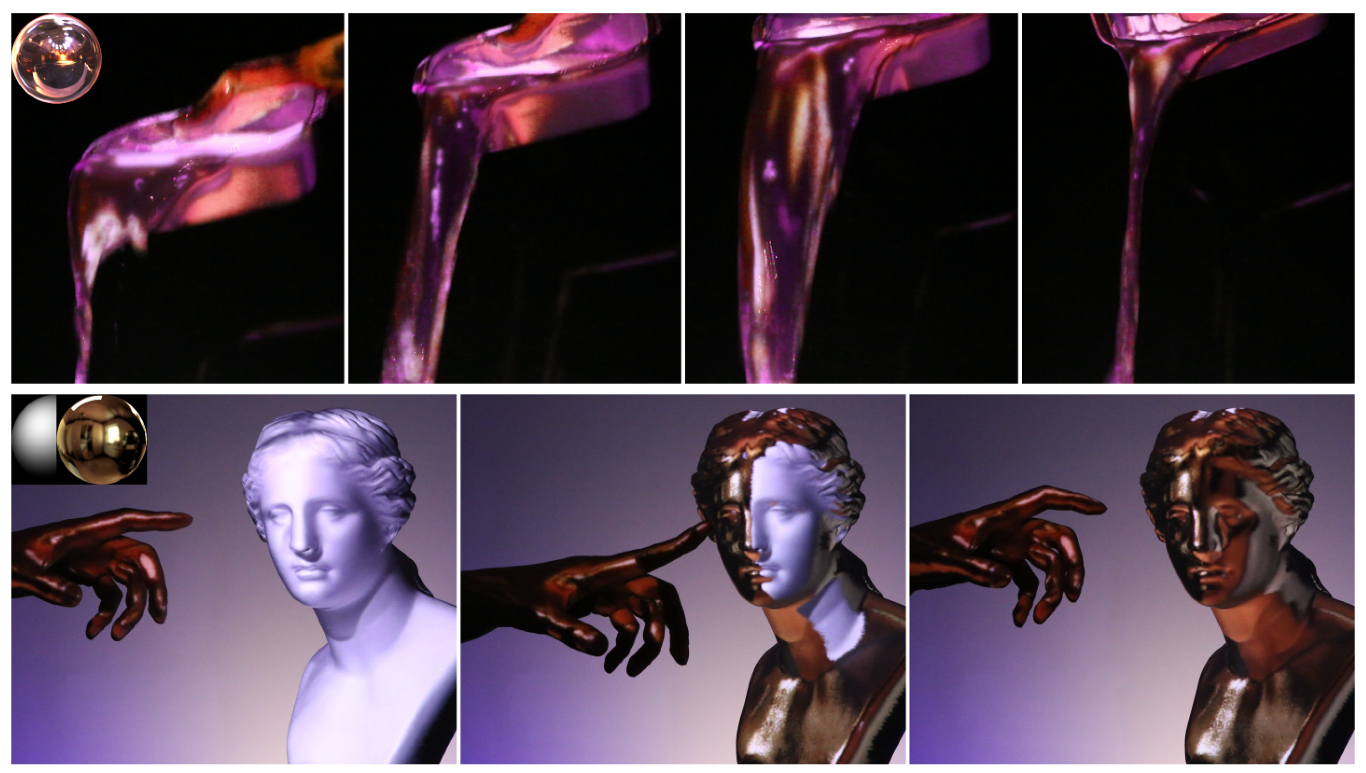
For tasks that require high-speed recognition of the 3D shape or pose and position of an object, a system often has to deal with the target with 2D images and markers while restricting the target or their motion [57,58,59]. On the other hand, once high-speed 3D measurement technology is established, these constraints will no longer be necessary, and tasks that require three-dimensional real-time feedback can be realized more flexibly. In particular, research in the fields of robotics and XR requires flexible 3D measurement to handle a wide variety of objects, and pioneering research has been proposed in the applications of high-speed 3D measurement. In the field of robotics, high-speed 3D measurement has been applied to the detection, position, and orientation recognition, and tracking of manipulation objects, mainly for the purpose of improving productivity. A 500 fps 3D measurement system installed on the end-effector side has been studied for the application of robotic arms [11], and a system that performs object tracking by 3D shape matching at 500 fps [12] in combination with a high-speed 2-axis stage has been proposed. In the field of XR, high-speed 3D measurement is mainly applied to spatiotemporal matching of real objects in the real world and computer graphics in the virtual world. In particular, dynamic projection mapping (DPM), in which projection mapping is applied to dynamic objects, requires high-speed, low-latency, and three-dimensional object recognition to project images onto a moving target without misalignment. For example, DPM onto rigid objects using 3D measurements at 500 fps [60], and a DPM system that measures surface normally at 500 fps [13] have been proposed. Figure 6 shows the DPM based on high-speed surface normal measurement for non-rigid bodies and fluids without any markers and shape models.

6. Discussion

In the previous sections, we focused mainly on the number of projected patterns and introduced standard structured light patterns and high-speed methods. In the structured light method, the number of projected patterns required for measurement is an important factor in achieving high speed. However, the structured light method does not physically sense 3D positions, and so image processing and analysis are always required after image capturing. Therefore, in order to discuss high-speed or low latency of a measurement system, not only the number of projected patterns but also the computational cost of the image processing must be taken into consideration. In particular, in recent years, as mentioned above, the number of required patterns has been reduced to a few, and projectors, which affect the actual projection time, have become faster, so the analysis of various methods will be conducted with a focus on computational complexity and parallelizability in the future. In fact, techniques have existed to acquire images for 3D measurement at frame rates of 1000 fps or even higher. However, it is only in recent years that the calculation of 3D points from an image can be finished in less than 1 ms and 3D vision provides real-time feedback based on 3D information. In response, there has also been an increase in demand for processing algorithms for 3D point clouds that can work at 1000 fps, and although some of these techniques have been developed, as introduced, they are still slow and in the developmental stage.On the other hand, as shown in Section 5.1, 3D measurement does not only pursue measurement speed. Even when measuring dynamic targets, there is a need to improve resolution, accuracy, and working distance without sacrificing high speed or low latency. We have to research on standard methods that can fairly evaluate these performance indicators from multiple angles without being dependent on the actual device or targets.

7. Conclusions

In this paper, we focused on high-speed 3D measurement methods with a high temporal resolution such as 1000 fps for applications that need to accurately recognize and immediately respond to dynamic objects. First, this paper started with the principle of 3D measurement and suitable methodology for dynamic objects, and then outlined both conventional and recent high-speed 3D measurement methods, focusing on the required number of frames, i.e., measurement speed. Additionally, the research to compensate for the disadvantage of high-speed 3D measurement and the applications that take advantage of the high speed and low latency were also described. The high-speed 3D measurement method using image processing has been improved by mathematical analysis as well as the development of peripheral vision devices, and the recent methods have achieved high performance enough for practical use. We expect that these high-speed 3D vision methods will be utilized in a wide range of industries.

Author Contributions

Writing—original draft preparation, L.M.; writing—review and editing, S.T.; supervision, M.I. All authors have read and agreed to the published version of the manuscript.

Funding

This research received no external funding.

Conflicts of Interest

The authors declare no conflicts of interest.

References

  1. Xu, J.; Xi, N.; Zhang, C.; Shi, Q.; Gregory, J. Real-time 3D shape inspection system of automotive parts based on structured light pattern. Opt. Laser Technol. 2011, 43, 1–8. [Google Scholar] [CrossRef]
  2. Li, Y.; Ibanez-Guzman, J. Lidar for Autonomous Driving: The Principles, Challenges, and Trends for Automotive Lidar and Perception Systems. IEEE Signal Process. Mag. 2020, 37, 50–61. [Google Scholar] [CrossRef]
  3. Xu, J.; Wang, H.; Zhang, J.; Cai, L. Robust Hand Gesture Recognition Based on RGB-D Data for Natural Human–Computer Interaction. IEEE Access 2022, 10, 54549–54562. [Google Scholar] [CrossRef]
  4. Li, J.; Guo, Y.; Zhu, J.; Lin, X.; Xin, Y.; Duan, K.; Tang, Q. Large depth-of-view portable three-dimensional laser scanner and its segmental calibration for robot vision. Opt. Lasers Eng. 2007, 45, 1077–1087. [Google Scholar] [CrossRef]
  5. Kosarevsky, S. Practical way to measure large-scale 2D parts using repositioning on coordinate-measuring machines. Measurement 2010, 43, 837–841. [Google Scholar] [CrossRef]
  6. Liu, D.; Chen, X.; Yang, Y.H. Frequency-Based 3D Reconstruction of Transparent and Specular Objects. In Proceedings of the 2014 IEEE Conference on Computer Vision and Pattern Recognition, Columbus, OH, USA, 23–28 June 2014; pp. 660–667. [Google Scholar] [CrossRef]
  7. Kadambi, A.; Taamazyan, V.; Shi, B.; Raskar, R. Depth Sensing Using Geometrically Constrained Polarization Normals. Int. J. Comput. Vis. 2017, 125, 34–51. [Google Scholar] [CrossRef]
  8. Yamashita, T.; Chiba, H.; Yamato, K.; Oku, H. Development of a coded exposure camera for high-speed 3D measurement using microscope. In Imaging Systems and Applications; Optica Publishing Group: Washington, DC, USA, 2018; p. ITu3B.2. [Google Scholar] [CrossRef]
  9. Guo, H.; Zhou, H.; Banerjee, P.P. Use of structured light in 3D reconstruction of transparent objects. Appl. Opt. 2022, 61, B314–B324. [Google Scholar] [CrossRef]
  10. Cheng, T.; Qin, L.; Li, Y.; Hou, J.; Xiao, C. An Adaptive Multiexposure Scheme for the Structured Light Profilometry of Highly Reflective Surfaces Using Complementary Binary Gray Code. IEEE Trans. Instrum. Meas. 2024, 73, 1–12. [Google Scholar] [CrossRef]
  11. Chen, J.; Liu, Y.; Gu, Q.; Aoyama, T.; Takaki, T.; Ishii, I. Robot-mounted 500-fps 3-D shape measurement using motion-compensated coded structured light method. In Proceedings of the 2014 IEEE International Conference on Robotics and Biomimetics (ROBIO 2014), Bali, Indonesia, 5–10 December 2014; pp. 1989–1994. [Google Scholar] [CrossRef]
  12. Namiki, A.; Shimada, K.; Kin, Y.; Ishii, I. Development of an Active High-Speed 3-D Vision System. Sensors 2019, 19, 1572. [Google Scholar] [CrossRef]
  13. Miyashita, L.; Watanabe, Y.; Ishikawa, M. MIDAS Projection: Markerless and Modelless Dynamic Projection Mapping for Material Representation. ACM Trans. Graph. 2018, 37, 196. [Google Scholar] [CrossRef]
  14. Weise, T.; Leibe, B.; Van Gool, L. Fast 3D Scanning with Automatic Motion Compensation. In Proceedings of the 2007 IEEE Conference on Computer Vision and Pattern Recognition, Minneapolis, MN, USA, 17–22 June 2007; pp. 1–8. [Google Scholar] [CrossRef]
  15. Boisvert, J.; Drouin, M.A.; Dicaire, L.G.; Picard, M.; Godin, G. Motion Compensation for Phase-Shift Structured-Light Systems Based on a Total-Variation Framework. In Proceedings of the 2017 International Conference on 3D Vision (3DV), Qingdao, China, 10–12 October 2017; pp. 658–666. [Google Scholar] [CrossRef]
  16. Hansard, M.; Lee, S.; Choi, O.; Horaud, R. Time-of-Flight Cameras: Principles, Methods and Applications; Springer Publishing Company: Berlin/Heidelberg, Germany, 2012. [Google Scholar]
  17. Geng, J. Structured-light 3D surface imaging: A tutorial. Adv. Opt. Photon. 2011, 3, 128–160. [Google Scholar] [CrossRef]
  18. Seitz, P. Quantum-Noise Limited Distance Resolution of Optical Range Imaging Techniques. IEEE Trans. Circuits Syst. I Regul. Pap. 2008, 55, 2368–2377. [Google Scholar] [CrossRef]
  19. Conroy, R.M.; Dorrington, A.A.; Künnemeyer, R.; Cree, M.J. Range imager performance comparison in homodyne and heterodyne operating modes. Three-Dimens. Imaging Metrol. 2009, 7239, 723905. [Google Scholar] [CrossRef]
  20. Bamji, C.; Godbaz, J.; Oh, M.; Mehta, S.; Payne, A.; Ortiz, S.; Nagaraja, S.; Perry, T.; Thompson, B. A Review of Indirect Time-of-Flight Technologies. IEEE Trans. Electron Devices 2022, 69, 2779–2793. [Google Scholar] [CrossRef]
  21. Miyashita, L.; Tabata, S.; Ishikawa, M. 3D Sensing Based on High-speed Image Processing and Applications (in Japanese). Laser Soc. Jpn. Rev. Laser Eng. 2023, 51, 215–219. [Google Scholar]
  22. Nose, A.; Yamazaki, T.; Katayama, H.; Uehara, S.; Kobayashi, M.; Shida, S.; Odahara, M.; Takamiya, K.; Matsumoto, S.; Miyashita, L.; et al. Design and Performance of a 1 ms High-Speed Vision Chip with 3D-Stacked 140 GOPS Column-Parallel PEs †. Sensors 2018, 18, 1313. [Google Scholar] [CrossRef] [PubMed]
  23. Okumura, K.; Oku, H.; Ishikawa, M. High-speed gaze controller for millisecond-order pan/tilt camera. In Proceedings of the 2011 IEEE International Conference on Robotics and Automation, Shanghai, China, 9–13 May 2011; pp. 6186–6191. [Google Scholar] [CrossRef]
  24. Iida, K.; Oku, H. Saccade Mirror 3: High-speed gaze controller with ultra wide gaze control range using triple rotational mirrors. In Proceedings of the 2016 IEEE International Conference on Robotics and Automation (ICRA), Stockholm, Sweden, 16–21 May 2016; pp. 624–629. [Google Scholar] [CrossRef]
  25. Oku, H.; Ishikawa, M. High-speed liquid lens for computer vision. In Proceedings of the 2010 IEEE International Conference on Robotics and Automation, Anchorage, AK, USA, 3–7 May 2010; pp. 2643–2648. [Google Scholar] [CrossRef]
  26. Watanabe, Y.; Narita, G.; Tatsuno, S.; Yuasa, T.; Sumino, K.; Ishikawa, M. High-speed 8-bit image projector at 1000 fps with 3 ms delay. In Proceedings of the 22nd International Display Workshops, Otsu, Japan, 9–11 December 2015; pp. 1421–1422. [Google Scholar]
  27. Watanabe, Y.; Ishikawa, M. High-speed and high-brightness color single-chip DLP projector using high-power LED-based light sources. In Proceedings of the 26th International Display Workshops, Sapporo, Japan, 27–29 November 2019; pp. 1350–1352. [Google Scholar] [CrossRef]
  28. Lippmann, U.; Aswendt, P.; Hoefling, R.; Sumino, K.; Ueda, K.; Ono, Y.; Kasebe, H.; Yamashita, T.; Yuasa, T.; Watanabe, Y. High-Speed RGB+IR Projector Based on Coaxial Optical Design with Two Digital Mirror Devices. In Proceedings of the International Display Workshops, Sapporo, Japan, 4–6 December 2021; p. 636. [Google Scholar] [CrossRef]
  29. Xu, X.; Fei, Z.; Yang, J.; Tan, Z.; Luo, M. Line structured light calibration method and centerline extraction: A review. Results Phys. 2020, 19, 103637. [Google Scholar] [CrossRef]
  30. Wu, H.B.; Chen, Y.; Wu, M.Y.; Guan, C.R.; Yu, X.Y. 3D Measurement Technology by Structured Light Using Stripe-Edge-Based Gray Code. J. Phys. Conf. Ser. 2006, 48, 537. [Google Scholar] [CrossRef]
  31. Lei, S.; Zhang, S. Flexible 3-D shape measurement using projector defocusing. Opt. Lett. 2009, 34, 3080–3082. [Google Scholar] [CrossRef]
  32. Zhang, Y.; Liu, B.; Zhou, P.; Wang, H. A review for three-step phase-shifting algorithms. Opt. Lasers Eng. 2025, 186, 108751. [Google Scholar] [CrossRef]
  33. Yu, H.; Lan, Y.; Yuan, Z.; Xu, J.; Lee, H. Phase Unwrapping in InSAR: A Review. IEEE Geosci. Remote Sens. Mag. 2019, 7, 40–58. [Google Scholar] [CrossRef]
  34. Gupta, M.; Nayar, S.K. Micro Phase Shifting. In Proceedings of the 2012 IEEE Conference on Computer Vision and Pattern Recognition, Providence, RI, USA, 16–21 June 2012; pp. 813–820. [Google Scholar] [CrossRef]
  35. Maruyama, M.; Tabata, S.; Watanabe, Y.; Ishikawa, M. Multi-pattern Embedded Phase Shifting Using a High-Speed Projector for Fast and Accurate Dynamic 3D Measurement. In Proceedings of the 2018 IEEE Winter Conference on Applications of Computer Vision (WACV), Lake Tahoe, NV, USA, 12–15 March 2018; pp. 921–929. [Google Scholar] [CrossRef]
  36. Tabata, S.; Maruyama, M.; Watanabe, Y.; Ishikawa, M. Pixelwise Phase Unwrapping Based on Ordered Periods Phase Shift. Sensors 2019, 19, 377. [Google Scholar] [CrossRef]
  37. Gao, H.; Takaki, T.; Ishii, I. GPU-based real-time structured light 3D scanner at 500 fps. In Real-Time Image and Video Processing 2012; Kehtarnavaz, N., Carlsohn, M.F., Eds.; International Society for Optics and Photonics SPIE: Bellingham, WA, USA, 2012; Volume 8437, pp. 194–202. [Google Scholar] [CrossRef]
  38. Wang, Y.; Zhang, S. Superfast multifrequency phase-shifting technique with optimal pulse width modulation. Opt. Express 2011, 19, 5149–5155. [Google Scholar] [CrossRef] [PubMed]
  39. Zuo, C.; Tao, T.; Feng, S.; Huang, L.; Asundi, A.; Chen, Q. Micro Fourier Transform Profilometry (μFTP): 3D shape measurement at 10,000 frames per second. Opt. Lasers Eng. 2018, 102, 70–91. [Google Scholar] [CrossRef]
  40. Wu, Z.; Zuo, C.; Guo, W.; Tao, T.; Zhang, Q. High-speed three-dimensional shape measurement based on cyclic complementary Gray-code light. Opt. Express 2019, 27, 1283–1297. [Google Scholar] [CrossRef] [PubMed]
  41. Wu, Z.; Guo, W.; Li, Y.; Liu, Y.; Zhang, Q. High-speed and high-efficiency three-dimensional shape measurement based on Gray-coded light. Photon. Res. 2020, 8, 819–829. [Google Scholar] [CrossRef]
  42. Nakagawa, S.; Watanabe, Y. High-Frame-Rate Projection with Thousands of Frames Per Second Based on the Multi-Bit Superimposition Method. In Proceedings of the 2023 IEEE International Symposium on Mixed and Augmented Reality (ISMAR), Sydney, Australia, 16–20 October 2023; pp. 741–750. [Google Scholar] [CrossRef]
  43. Zhou, P.; Zhu, J.; Jing, H. Optical 3-D surface reconstruction with color binary speckle pattern encoding. Opt. Express 2018, 26, 3452–3465. [Google Scholar] [CrossRef]
  44. Yin, W.; Zhao, H.; Ji, Y.; Deng, Z.; Jin, Z.; Feng, S.; Zhang, X.; Wang, H.; Chen, Q.; Zuo, C. High-Resolution, Wide-Field-of-View, and Real-Time 3D Imaging Based on Spatial-Temporal Speckle Projection Profilometry with a VCSEL Projector Array. ACS Photonics 2024, 11, 498–511. [Google Scholar] [CrossRef]
  45. Watanabe, Y.; Komuro, T.; Ishikawa, M. 955-fps Real-time Shape Measurement of a Moving/Deforming Object using High-speed Vision for Numerous-point Analysis. In Proceedings of the 2007 IEEE International Conference on Robotics and Automation, Rome, Italy, 10–14 April 2007; pp. 3192–3197. [Google Scholar] [CrossRef]
  46. Tabata, S.; Noguchi, S.; Watanabe, Y.; Ishikawa, M. High-speed 3D sensing with three-view geometry using a segmented pattern. In Proceedings of the 2015 IEEE/RSJ International Conference on Intelligent Robots and Systems (IROS), Hamburg, Germany, 28 September–2 October 2015; pp. 3900–3907. [Google Scholar] [CrossRef]
  47. Scharstein, D.; Szeliski, R.; Zabih, R. A taxonomy and evaluation of dense two-frame stereo correspondence algorithms. Int. J. Comput. Vis. 2002, 47, 7–42. [Google Scholar] [CrossRef]
  48. Hartley, R.; Zisserman, A. Multiple View Geometry in Computer Vision, 2nd ed.; Cambridge University Press: Cambridge, UK, 2004. [Google Scholar]
  49. Miyashita, L.; Tabata, S.; Ishikawa, M. High-Speed and Low-Latency 3D Sensing with a Parallel-Bus Pattern. In Proceedings of the 2022 International Conference on 3D Vision (3DV), Prague, Czech Republic, 12–16 September 2022; pp. 291–300. [Google Scholar] [CrossRef]
  50. Chung, F.; Diaconis, P.; Graham, R. Universal cycles for combinatorial structures. Discret. Math. 1992, 110, 43–59. [Google Scholar] [CrossRef]
  51. Horan, V.; Stevens, B. Locating patterns in the de Bruijn torus. Discret. Math. 2016, 339, 1274–1282. [Google Scholar] [CrossRef]
  52. Nehab, D.; Rusinkiewicz, S.; Davis, J.; Ramamoorthi, R. Efficiently Combining Positions and Normals for Precise 3D Geometry. In ACM Transactions on Graphics (TOG); Association for Computing Machinery: New York, NY, USA, 2005; pp. 536–543. [Google Scholar] [CrossRef]
  53. Miyashita, L.; Kimura, Y.; Tabata, S.; Ishikawa, M. High-Speed Depth-Normal Measurement and Fusion Based on Multiband Sensing and Block Parallelization. J. Robot. Mechatronics 2022, 34, 1111–1121. [Google Scholar] [CrossRef]
  54. Satoshi Tabata, Y.W.; Ishikawa, M. High-speed 6-DoF Tracking Based on Small-Displacement Assumption. IEICE Trans. Inf. Syst. 2018, J101-D, 1539–1550. [Google Scholar]
  55. Besl, P.; McKay, N.D. A method for registration of 3-D shapes. IEEE Trans. Pattern Anal. Mach. Intell. 1992, 14, 239–256. [Google Scholar] [CrossRef]
  56. Satoshi Tabata, Y.W.; Ishikawa, M. Development of a Compact High-speed 3D Scanner. J. Robot. Soc. Jpn. Lett. 2024, 42, 82–85. [Google Scholar] [CrossRef]
  57. Kato, H.; Billinghurst, M. Marker tracking and HMD calibration for a video-based augmented reality conferencing system. In Proceedings of the 2nd IEEE and ACM International Workshop on Augmented Reality (IWAR’99), San Francisco, CA, USA, 20–21 October 1999; pp. 85–94. [Google Scholar] [CrossRef]
  58. Klein, G.; Murray, D. Parallel Tracking and Mapping for Small AR Workspaces. In Proceedings of the 2007 6th IEEE and ACM International Symposium on Mixed and Augmented Reality, Nara, Japan, 13–16 November 2007; pp. 225–234. [Google Scholar] [CrossRef]
  59. Kagami, S.; Hashimoto, K. Animated Stickies: Fast Video Projection Mapping onto a Markerless Plane through a Direct Closed-Loop Alignment. IEEE Trans. Vis. Comput. Graph. 2019, 25, 3094–3104. [Google Scholar] [CrossRef]
  60. Hisaichi, S.; Sumino, K.; Ueda, K.; Kasebe, H.; Yamashita, T.; Yuasa, T.; Lippmann, U.; Aswendt, P.; Höfling, R.; Watanabe, Y. Depth-Aware Dynamic Projection Mapping using High-speed RGB and IR Projectors. In Proceedings of the SIGGRAPH Asia 2021 Emerging Technologies, Tokyo, Japan, 14–17 December 2021. [Google Scholar] [CrossRef]
Figure 1. Measurement principle in a structured light method. In this figure, a pattern including some lines is adopted as a structured light. This pattern is a kind of application of a light section method in Section 3.
Metrology 05 00024 g001
Figure 2. Conventional structured light patterns.
Metrology 05 00024 g002
Figure 3. Segment pattern [46]. This pattern is composed of many primitives containing the bar and points. Based on the number of points around a bar, the correct corresponding bar on the epipolar lines is easily identified and the phase is determined.
Metrology 05 00024 g003
Figure 4. Parallel-bus pattern [49]. This pattern is composed of repeated three lines: MSB, CLK, and LSB. The CLK line is a clock signal to find out the switching point of data bits in MSB and LSB lines. The MSB and LSB lines contain the phase data as a De Bruijn torus. As parallel bus communication, this pattern enables high-speed decoding of binary data, i.e., phase information.
Metrology 05 00024 g004
Figure 5. High-speed measurement and integration of depth and normal [53]. The target surface has the detailed curving patterns (a) and it is not easy to measure the detail by depth sensing. Surface normal measurement using the photometric stereo method can provide the detail but cannot measure the absolute position instead. This research introduces high-speed sensing setup of both of them and the real-time integration algorithm (bd).
Metrology 05 00024 g005
Figure 6. MIDAS projection [13]. This system achieves dynamic projection mapping even onto non-rigid bodies and fluids without markers and shape models by measuring surface normals in real time. The materials of the liquid and the statue are virtually changing by the projection.
Metrology 05 00024 g006
Disclaimer/Publisher’s Note: The statements, opinions and data contained in all publications are solely those of the individual author(s) and contributor(s) and not of MDPI and/or the editor(s). MDPI and/or the editor(s) disclaim responsibility for any injury to people or property resulting from any ideas, methods, instructions or products referred to in the content.