Abstract
Freight wagons in Europe have used Y25 bogies since the 1960s. Although very cost-effective, Y25 suffers from intrinsic limitations due to its architecture and running behaviour. This study introduces an innovative lightweight bogie, named 4L bogie, aimed at removing those limitations as well as improving running dynamics and track friendliness. This task was particularly challenging as the high ratio between laden and tare weight (up to 5:1) forced us to use a non-conventional suspension system and an innovative architecture of frame, reducing the mass by about 15% and the yaw moment of inertia by about 30% with respect to the Y25 bogie. Maintenance issues were addressed by reducing the number of components and easing overhaul, while the new design was validated from both the structural and the running dynamics point of view, assessing its interaction with the track in terms of stability, curving behaviour and the vertical response of the 4L bogie. Stability was improved by about 20% even in empty conditions and high conicity at the wheel/rail contact. Vertical dynamic force on a straight track, evaluated according to the Ride Force Count metric, and wear behaviour on sharp and mild curves were considerably reduced, leading to an improved track friendliness of the bogie.
1. Introduction
1.1. Current Design of Freight Bogies
European freight operations have no dedicated lines, resulting in a mixed train operation with passenger commuter trains. On the other hand, high-speed trains (with a maximum speed equal to or higher than 200 km/h) have dedicated lines, where track geometry quality must be as high as possible to guarantee safe operation at high speeds.
Freight trains are characterized by a low average speed, mainly due to their complex management during handling and shunting, causing long stop-times [1,2]. However, the lower permitted speed with respect to passenger trains contributes to increasing the shipping times and reducing the efficiency of the track utilization. The maximum speed of freight wagons is limited (100 km/h in laden conditions and 120 km/h in empty conditions) due to braking issues (which is usually performed with brake blocks acting on the tread of the wheel) and the higher dynamic loads introduced by the running gear. While passenger vehicles can run on curved tracks with a lateral non-compensated acceleration anc equal to 1 m/s2, for freight wagons, it is limited to 0.6 m/s2 to account for higher lateral loads.
The increase in the efficiency of goods transport by means of freight wagons is one of the main objectives for the next few years, and projects have been dedicated to developing an innovative freight bogie with superior characteristics with respect to the current Y25 bogie [3,4]. Several aspects have to be involved in this process, with special attention required for wagon design, monitoring and maintenance. As lower noise, greater load capacity, lower downtime and better ride quality are requested by railway companies today, bogie designers face very challenging problems. The design of the Y25 bogie, standardized in 1967, has been improved in the last few years, and several versions are available today. One example is shown in Figure 1.
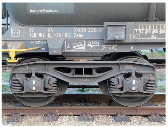
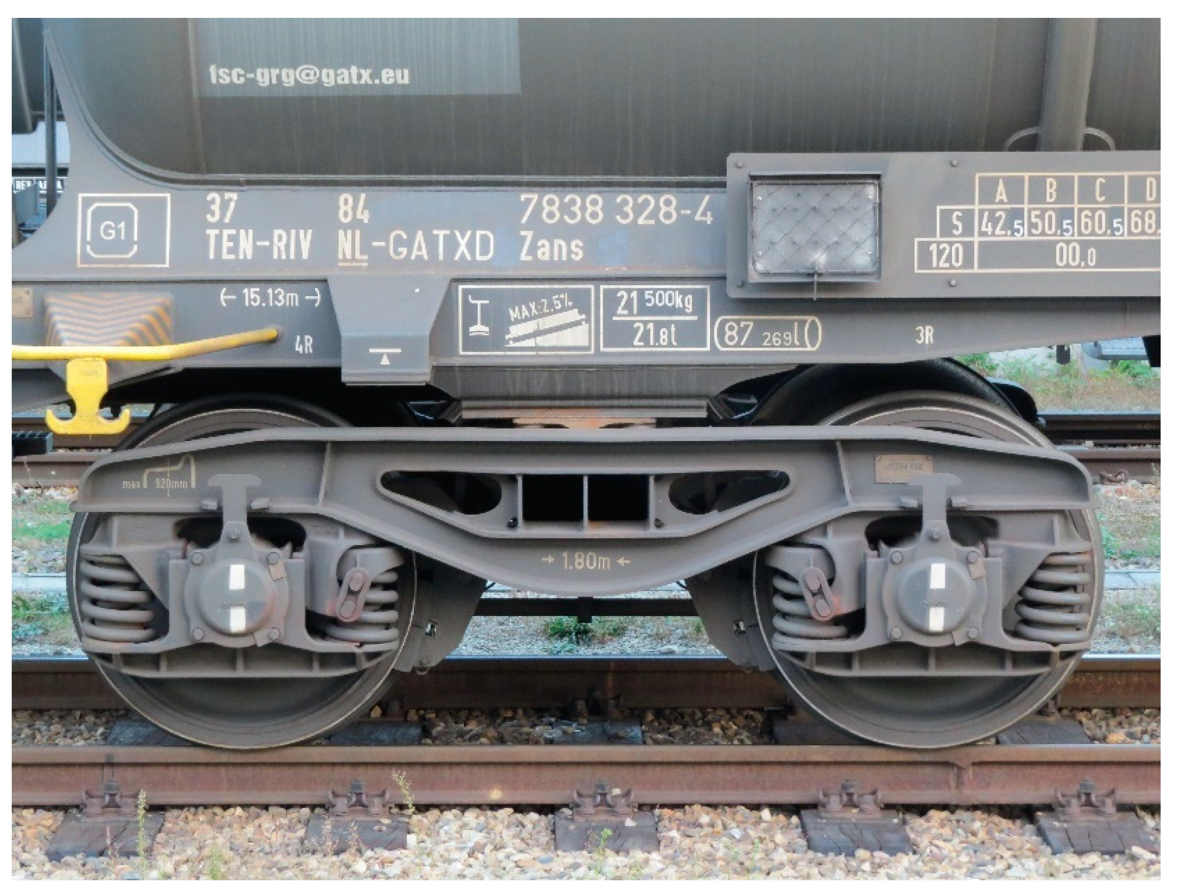
Figure 1.
Side view of the Y25 bogie with tread braking.
Today, the mass of conventional Y25 bogies is particularly optimized, with values that can reach 4 t if tread-braking on wheels is applied instead of disc brakes. Certain versions that can run up to 140 km/h in empty conditions or at 120 km/h if carrying low-density goods (17–18 t/axle) are available today. One example is the Y25Lsi(f) [5] from Greenbrier that is equipped with brake discs and a mass of over 5 t.
The maximum axle load is currently bound to increase from 22.5 t/axle to 25 t/axle. For example, the GB25RS [5] bogie is designed for 25 t/axle, with a maximum speed of 100 km/h that can reach 120 km/h if the axle load is reduced to 22.5 t/axle and disc brakes are installed, with a considerable increase in mass (from about 4 t with brake shoes to about 5 t with brake discs). Moreover, metal–rubber cushions are installed above the axleboxes to reduce vertical dynamic forces. Another example of a 25 t/axle bogie is RC25NT [6], a bogie equipped with brake discs that can run up to 120 km/h if the axle load is reduced to 22.5 t/axle. This bogie, which is equipped with progressive secondary suspensions, rubber primary springs and cross bracing, is particularly advanced, resulting in a maximum tested speed of 160 km/h.
To reduce dynamic forces exerted by the running gear, softer suspensions are now used, for example, in TVP2007 or TVP2009–R [7], of which the stoke reaches 50 mm. Cross bracing is used to steer the wheelsets, improving the curving ability of the bogie, and 120 km/h can be reached in loaded conditions (up to 25 t/axle), but the mass is not lower than 4.8 t, and only tread braking is available. Another kind of track-friendly bogie is the TF25 [8], which uses hydraulically damped primary coil springs and rubber side-bearers. The maximum speed is also 120 km/h in loaded conditions (25 t/axle), and compact tread braking units are applied. The only freight bogie available to reach 160 km/h at 18 t/axle is the DRRS25LD [9] bogie, which is equipped with a double rubber toroidal ring and brake discs, and its mass is about 5 t.
In this study, an innovative bogie architecture for freight wagons is described. The new design allows for a straightforward replacement of the Y25 bogie, as the standard interfaces with the wagon body are maintained, but new concepts for the frame and the suspensions are introduced. Inboard bearings, combined with a pyramidal arrangement of the frame, permit a reduction in the total mass of up to 4 t, even if brake discs are applied. The number of components is reduced with an innovative arrangement of the primary suspension that connects the two wheels on the same side, which can reduce vertical dynamic forces without the use of rubber, subjected to ageing, or hydraulic dampers, which require expensive and regular maintenance.
Both the vertical and lateral response of the bogie were evaluated by finite element (FE) and multibody (MBS) simulations, where different types of track irregularities were modelled. Benefits for the lateral dynamics are given by lower mass and moment of inertia around the vertical axis, with results that proved the bogie to be stable in tangent tracks up to 140 km/h in empty conditions. Considering the peculiar arrangement of the suspension system, special attention was given to short wavelength irregularities. Dissipated energy at the wheel–rail contact was evaluated by calculating values of Tγ (or Tgamma, i.e., “wear number”) in curves and vertical dynamic forces at the maximum speed.
1.2. Description of the Innovative Freight Bogie
Inboard bearings bogies (inside frame bogies) are a consolidated solution for passenger wagons. Since the development of the B5000 bogie [10], inboard bearings have been extensively used on passenger vehicles in the UK due to relevant advantages in terms of Track Access Charge (TAC) reduction. The main advantage of this kind of bogie is the more compact design and therefore a lower moment of inertia about the vertical axes (yaw), leading in many cases to a lower wheelbase (distance between the axles of a bogie) and therefore increasing the steering capacity in sharp curves (called track friendliness) without compromising stability at high speed on a straight track. A relevant mass reduction is also reached with respect to outboard bearing bogies, as the compact design reduces bending moments due to vertical and lateral loads, leading to an optimized bogie frame structure.
Today, almost all bogie manufacturers have in their portfolio inboard bearing bogies. FlexxEco from Bombardier (ICE4), SF7000 from Siemens (MIREO) and trailer bogies of Class 800/801 from Hitachi are only some examples. An inboard bearing bogie for freight wagons, the LEILA bogie, has been proposed in the past [11]. However, it included rubber primary springs, hydraulic dampers, brake discs and cross bracing, resulting in high production costs on a large scale, even if advantages were proven during line tests.
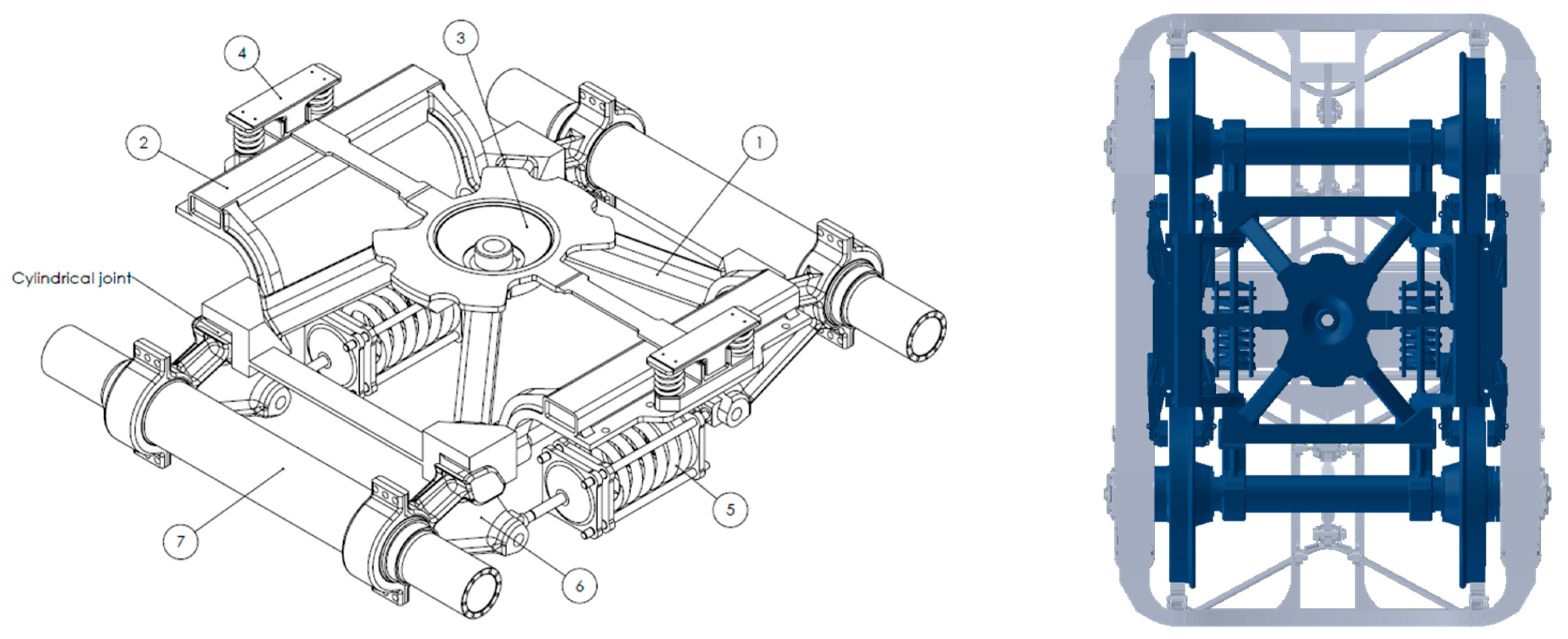
Figure 2 (left) shows the main frame of the innovative bogie composed of a 1: pyramidal frame; 2: supporting arm for side bearer and brake callipers for wheel web-mounted discs (or compact tread braking units); 3: centre bowl; 4: side bearers; 5: horizontal coil springs with single-stage progressive stiffness; 6: swinging arm; and 7: non-rotating axlebridge for AIR Wheelset [12] (or inboard bearings axle). The primary suspension acts in the longitudinal direction, as in the Munchen–Kassel bogie [13], with the difference that each spring connects the two swinging arms on one side and consequently the two wheelsets, replacing the eight springs used on each side of a Y25 bogie. Therefore, vertical movements of the wheelset and the bogie are transformed into horizontal movements by the swinging arm, and load-dependent friction damping is provided by the cylindrical pin connection between the arm and the frame.
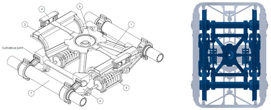
Figure 2.
Main frame of the 4L bogie with detail of the components (left) and comparison of the overall dimension between 4L (blue shape) and Y25 bogie (grey shape) (right).
The 4L bogie is designed with a conventional centre bowl and two side bearers to guarantee a direct replacement on standard wagons. With the inside frame architecture, it is possible to reduce the overall dimensions compared to a conventional Y25 bogie, as shown in Figure 2 (right). The mass of the main frame is about 1000 kg. The wheelset mass is about 1400 kg, with wheel web-mounted brake discs and brake callipers weighing 100 kg each. The final mass of the bogie equipped with disc brakes is therefore 4200 kg. The impact of brake calipers and discs on the total mass is considerable, and a version with an inboard bearing wheelset with thermostable wheels (about 1100 kg) and four compact tread braking units (60 kg each) can further reduce the weight to 3600 kg. The yaw moment of inertia of the bogie is reduced by about 30% with respect to the Y25, suggesting both better stability on straight tracks and better curving behaviour on curved tracks.
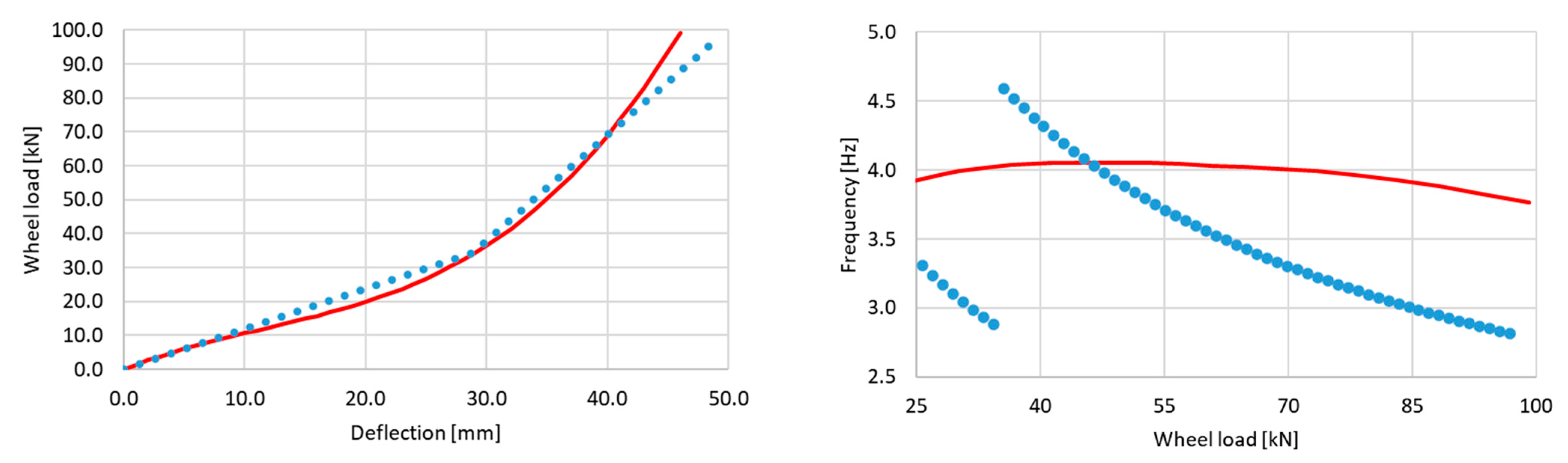
The Y25 bogie has a bi-linear suspension made of four springs for each wheel (Y25 has in total sixteen springs), two of them working in parallel: the outer one is softer and works alone in empty condition, the inner one is stiffer and starts working when the inner spring is lowered by 10 mm due to the wheel load. This behaviour generates a discontinuity in the suspension characteristics, while the progressive spring (only two per bogie) of the new suspension arrangement has a continuously increasing stiffness, as shown in Figure 3 (left), and its natural frequency calculated according to Equation (1) as a function of the suspension stiffness K and the wheel load F is nearly constant with the increase in the wagon mass. The resulting vertical frequency is about 4.0 Hz, as shown in Figure 3 (right).

Figure 3.
Force–deflection curve Y25 (dotted blue line) and new bogie (solid red line) (left) and vertical frequency of Y25 (dotted blue line) and 4L bogie (red solid line) (right).
The progressive stiffness leads to an improvement in the vertical dynamic behaviour of the bogie, especially in empty and partially laden conditions. Additionally, the swinging arm rotation transforms the vertical wheel movements into longitudinal displacements of the spring, reducing the part of dynamic force transmitted to the frame and the wagon. With this arrangement, the apparent dynamic spring stiffness depends on the kind of track irregularities, and two possible scenarios can be considered:
- If the track irregularity has a wavelength such that the front and rear wheels of each side of the bogie move in phase, the swinging arms rotate in the opposite direction, and the spring is stretched equally in both directions with respect to its middle plane. In this case, the dynamic apparent stiffness is half of the nominal spring stiffness.
- If track irregularity has a wavelength such that the front and rear wheels move in counter phase, the swinging arms rotate in the same direction and the spring is not stretched, showing a dynamic apparent stiffness equal to zero.
Moreover, while curving due to the lateral non-compensated acceleration, the wagon over the bogie experiences a certain roll angle, increasing the load on the outer wheels with respect to the inner ones. The roll angle must be limited to avoid the complete unloading of the inner side and then the roll-over of the vehicle. While this load transfer does not affect the dynamics of conventional bogies, the increase in the load of the external wheels coupled with the suspension arrangement of the 4L bogie generates better steering performance as it allows the wheelset to align radially when the vehicle runs with lateral acceleration greater than zero. In such case, the external swinging arms rotate more than the internal ones, generating an outer wheelbase greater than the internal one.
2. Material and Methods
2.1. Finite Element Model
The static and dynamic behaviour of the new freight bogie is strongly affected by the structural strength of the frame, which was assessed according to EN13749 [14] following the indications inside the example programme for freight bogies with central pivot and side bearers. Both static (exceptional loads) and fatigue (normal loads) conditions were evaluated, with a maximum axle load of 22.5 t/axle.
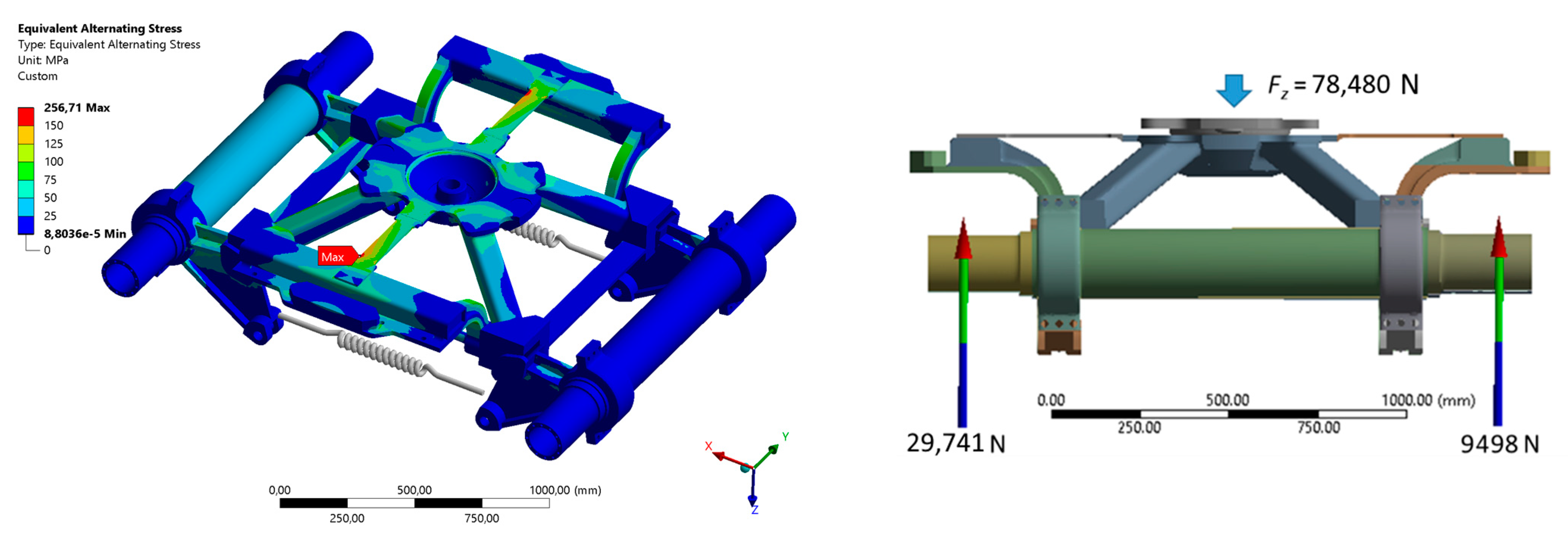
However, some load cases were added to improve the fatigue assessment, considering also different conditions with respect to the dynamic vertical unbalanced load (±30% superimposed to the static load) and lateral loads (pulsating from zero to the maximum value) that simulate the bogie running in curves. For example, cyclic stress due to loads coming from the repetition of left and right curves was implemented in the calculations, inducing torsional stresses due to alternating lateral loads, alternating track twists and alternating vertical loads on side bearers. The fatigue limit of S355 steel sheets was considered according to DVS1612 [15]. Figure 4 (left) shows a stress map for the alternating curves load case.

Figure 4.
Results of the FEM simulations in terms of equivalent alternating stress due to curving load case (left) and force distribution due to twist case (right).
A certain flexibility of the pyramidal frame is needed to guarantee the vertical force equalization over a twisted track. In fact, due to the primary suspension arrangement and the low static load when empty, the spring flexibility is unable to compensate for wheel-load variation, maintaining the wheel unloading factor ΔQ/Q lower than 0.6, which is the common limit used in railway dynamics to assess safety on a twisted track. This load case was simulated considering a vertical static load on the centre bowl equal to 8 t, i.e., 78,480 N (19,620 N for each wheel) and 9 mm (i.e., 0.5% of the wheelbase) of twist. The resulting wheel unloading calculated as the vertical wheel load variation ΔQ with respect to the wheel static load Q was (19,620 − 9498)/19,620 = 0.52, as shown in Figure 4 (right).
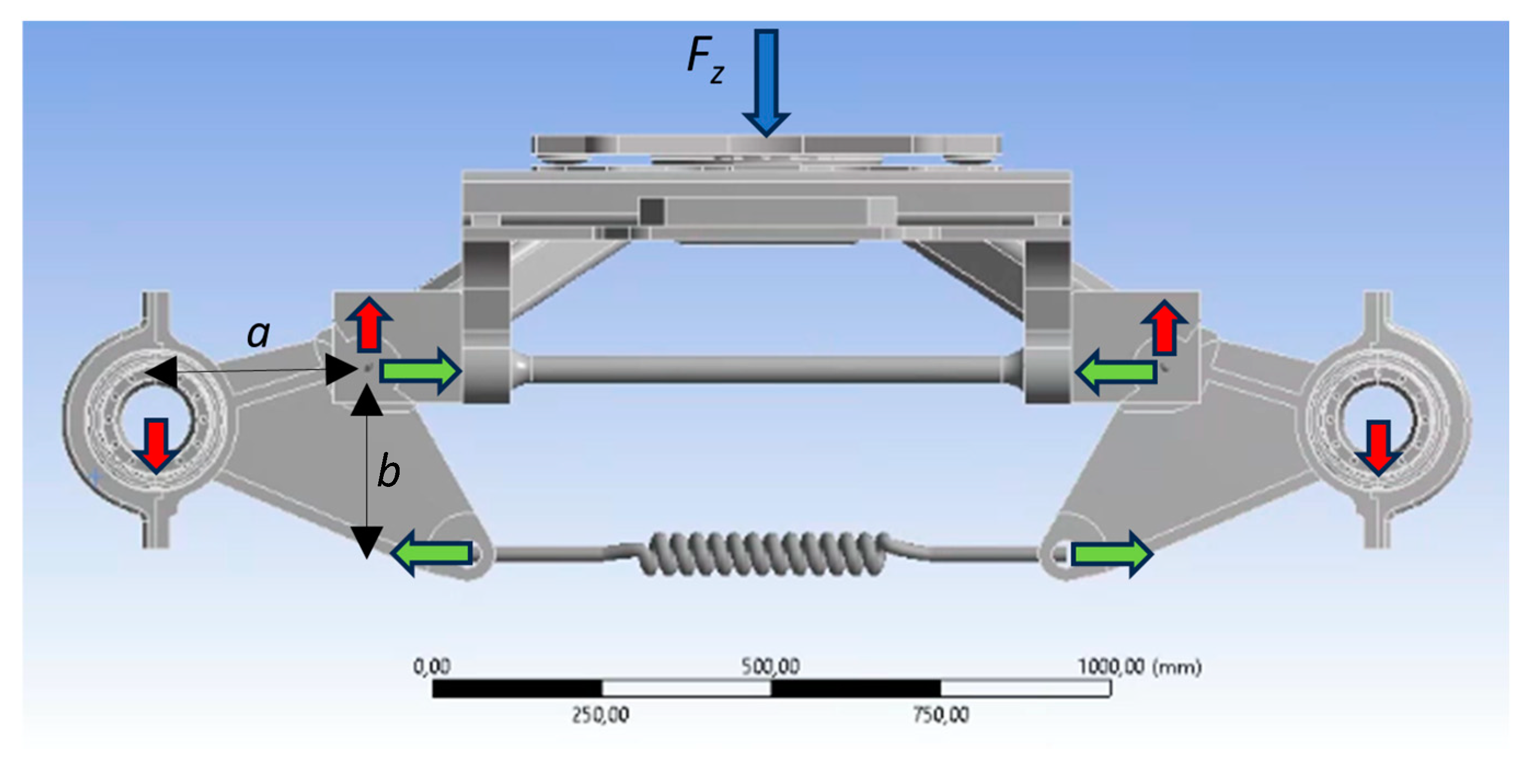
The vertical load Fz due to the wagon mass acts on the centre bowl of the bogie. Each swinging arm transfers to the wheelsets a vertical load equal to Fz/4, while the total force passing through the cylindrical joint between the swinging arm and the pyramidal frame results from the vertical load Fz/4 and longitudinal load due to the rotation of the swinging arm and the consequent spring reaction. This force is equal to (Fz/4)(a/b), where a/b is the ratio between the longitudinal and the vertical length of the swinging arm, as shown in Figure 5. In the current design, the ratio a/b is equal to 1.14.
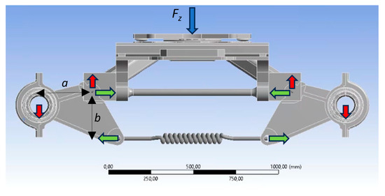
Figure 5.
Reaction forces of the cylindrical joint connecting the swinging arm and the pyramidal frame due to the vertical load Fz (blue arrow). Red arrows are equal to Fz/4, while green arrows are equal to (Fz/4)(a/b).
Even if these longitudinal loads generate additional stresses on the frame compared to the Y25 bogie, the pyramidal structure is designed to avoid bending moments as much as possible. In the Y25, the vertical load Fz is directly reacted at the wheels, which are 1.8 m distant, generating relevant bending on the frame. Lateral and longitudinal loads are transmitted by the cylindrical joint with no major differences with respect to the Y25 axleboxes, but also, in this case, bending on the frame is reduced thank to the compact design of the pyramidal structure.
The results in terms of structural strength and flexibility have been considered sufficient to evaluate the dynamic behaviour of the bogie, developing an MBS model that includes the pyramidal frame as a flexible body. From the modal analysis of the frame, a modal neutral file (MNF) was extracted, specifying the interface nodes for the other components of the MBS model. This file can be applied to the multibody model, as shown in Figure 6.
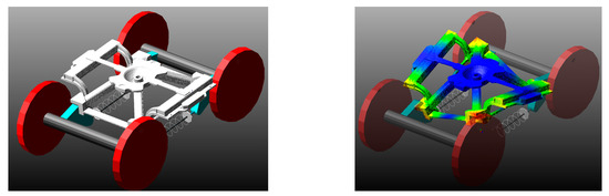
Figure 6.
MBS model of the bogie (left) and first eigenmode of the pyramidal frame included in the MBS model as flexible body (right).
2.2. Vehicle and Track Models
An MBS model was developed with the VI-Rail software package [16] to assess the running dynamics of the new bogie. The model represents a Sgnss 60′ intermodal wagon, equipped with Y25Ls(s) bogies. The distance between bogie pivots was 14.2 m, and both empty and laden wagon conditions were evaluated, with resulting axle loads of 4.25 t and 22.5 t, respectively. The wagon body frame was modelled with two rigid bodies connected by an elastic element to simulate its torsional stiffness. The torsional coefficient was set to 0.5 × 10¹⁰ kNmm2/rad, which is the minimum value for dispensation from the on-track test for a typical wagon equipped with Y25 bogies [17].
The centre bowl was modelled with a spherical joint with Coulomb friction with a friction coefficient µ = 0.2. Side bearers were modelled using non-linear elastic elements considering a 1 mm clearance in the longitudinal direction before solid-to-solid contact (modelled with high stiffness) and a preload of 16 kN in the vertical direction. Vertical stiffness was 5.7 × 10⁵ N/m, and a maximum vertical movement of 12 mm was allowed before solid-to-solid contact. Friction was modelled according to the Kolsch method with a friction coefficient µ = 0.35 [18]. The rotational behaviour of the model complied with the requirements of EN14363 standard [19], where the yaw resistance X of the bogie, calculated according to (2), was lower than 0.16 for the empty wagon and 0.1 for the laden wagon.
where P0 is the nominal axle load in kN and 2a+ is the bogie wheelbase. The total value of the yaw torque resistance Mz given by the centre bowl and the side bearers, shown in Figure 7, was calculated for both empty (Mz = 10 kNm) and laden condition (Mz = 23 kNm), resulting in an X equal to 0.13 and 0.06, respectively.
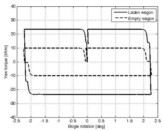
Figure 7.
Torque resistance given by the centre bowl and side bearers.
The swinging arms relate to the pyramidal frame by cylindrical joint connection, and Coulomb friction was added with µ = 0.3 to model damping during the vertical motion of the wheels. The pyramidal frame was modelled with a flexible body, and the empty wagon model was tuned with the results of the FEM track twist simulations described in the previous paragraph, without considering the effect of wagon frame (torsional stiffness of the wagon body set to zero).
Track flexibility has a relevant influence in the evaluation of railway vehicles dynamics. The track was modelled as a continuous moving support in which rails could be rigidly connected to the ground or using flexible connections between the ground and the sleeper, and between the sleeper and the rail. This introduced stiffness and damping properties to simulate the effect of ballast and other elastic elements placed under the rail (rail pads). More advanced modelling strategies are also available in modern software packages to include the effect of rail flexibility and discontinuous sleeper support, but the computational effort strongly increases. Proper values of track flexibility are not easy to find, and often, simulations are conducted according to the Manchester Benchmark [20], which is one of the main reference cases for MBS modelling of railway vehicles.
To address the dynamic effects of the MBS model, lateral and vertical irregularities (i.e., alignment and longitudinal level defects) were added to the track geometry, which are described in the next paragraph for each kind of simulation.
3. Results
3.1. Lateral Dynamics on Straight Track
While a railway vehicle runs on a straight track, the profiles of the wheel and rail cause a self-centring effect, preventing the vehicle from running misaligned with respect to the centre of the track. According to Klingel theory, this movement is a harmonic undamped function with wavelength L according to Equation (3), where R is the wheel radius, s is the distance between the nominal rolling radius of the wheels (typically 1.5 m for standard gauge wheelsets), and γ is the conicity at the wheel/rail contact.
However, this applies only for an uncoupled free wheelset with conical profiles and without considering the dynamic effects exerted by the vehicle, and this lateral motion is more complex than a perfect sinusoid. At low speeds, if the vehicle is laterally excited by a track misalignment, the resulting oscillatory motion is damped, and the vehicle is considered stable, but increasing the speed, the motion can become undamped, and the speed at which this happens is called critical speed.
Finding the critical speed of a railway vehicle is a complex matter [21], and an exact solution does not exist. This is particularly challenging for freight bogies in which several sources of non-linearities can be found due to the use of friction surfaces as damping. Krishna [22] compared the stability of a standard design and an improved design (with cross-bracing and softer suspensions) of the Y25 bogie in empty conditions, showing a critical speed of 115 km/h and 135 km/h, respectively. Molatefi [23] found that Y25 shows instability at speeds as low as 60 km/h. However, the real dynamic behaviour suggests that limit cycles at relatively slow speeds cannot compromise running safety, and in practice, it is sufficient to assess the stability of the vehicle at the maximum permitted speed by measuring lateral forces or lateral accelerations according to EN14363 [19], where the maximum RMS value of the sum of guiding forces ΣY on left and right wheels (filtered in the range f0 ± 2 Hz) is compared with half of the Prud’Homme limit (4):
where k1 = 0.85 for freight vehicles, P0 [kN] is the axle load and f0 the instability frequency of undamped oscillations. For the new bogie model, the stability assessment values are 10.16 kN for the empty wagon and 35.52 kN for the laden wagon.
While it is nearly impossible to know the instability frequency in practice, the filtering lower and upper limit frequencies were applied as stated by the standard (0.4 Hz and 12 Hz); numerically, these values can be found by analysing the lateral dynamics of the vehicle on an ideal track.
To investigate the stability of the new freight, bogie simulations on an ideal track were performed to find the critical speed and frequency. Stability simulations were performed with an S1002 wheel profile, coupled with a 60E1 rail profile inclined at 1:40. Differently from Klingel theory, the actual wheel and rail coupled together do not generate a conical profile and the value of conicity γ changes as the wheelset moves laterally.
Therefore, to describe the wheelset behaviour in real conditions, a value of equivalent conicity γeq is given [24]. For the chosen wheel and rail profiles, the equivalent conicity is 0.17. Even if these profiles are unworn for both wheel and rail, a survey performed during the DYNOTRAIN project described in a recent CEN Technical Report [25] shows that even in worn–worn condition, the mean values of equivalent conicity are in the range between 0.1 and 0.25.
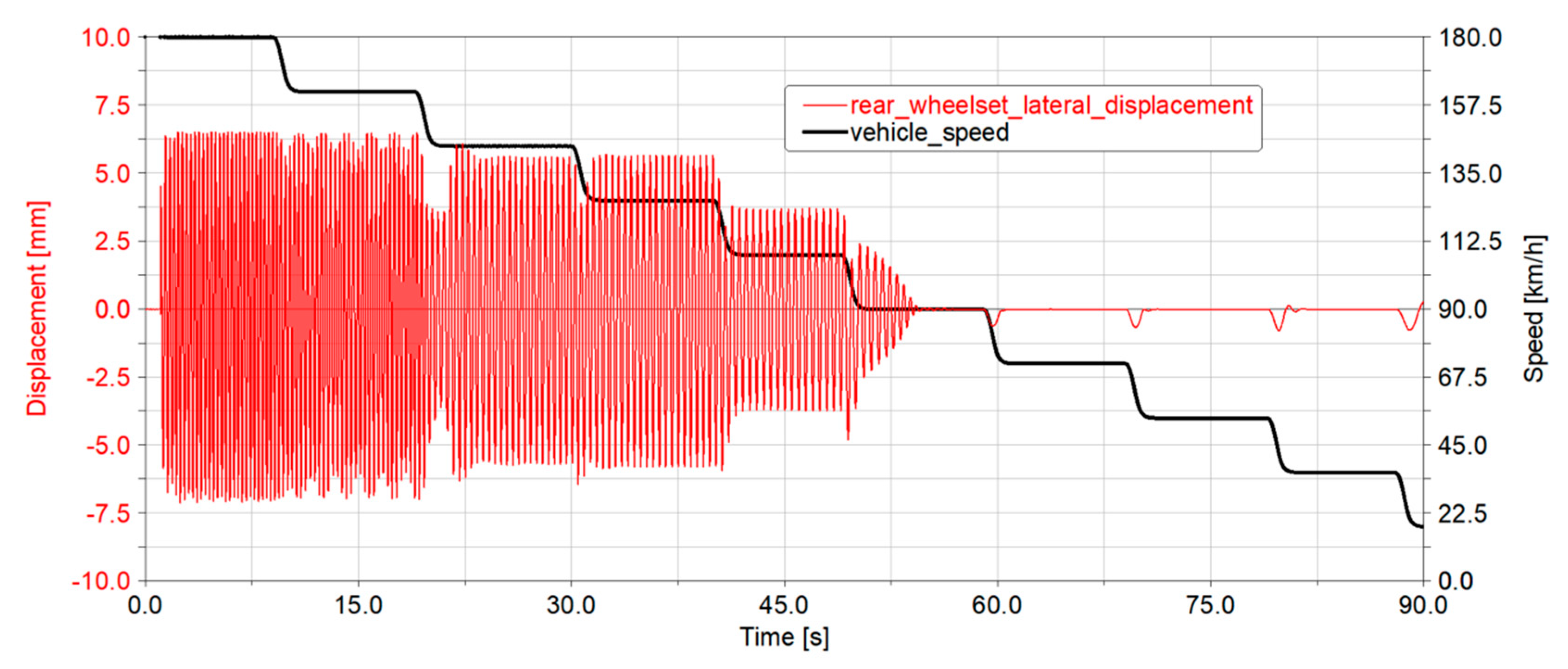
The vehicle was excited with a lateral misalignment at relatively high speeds, activating instability conditions, and then the speed was reduced by steps to find the minimum speed at which the lateral displacement of the wheelset was damped. This is shown in Figure 8, where undamped oscillations are found down to 108 km/h. However, lateral oscillations between 108 km/h and 144 km/h are related to limit cycles that do not completely recover the maximum play between the wheel and the rail (about 6.5 mm), suggesting that the critical speed according to the limit (4) could be higher. This is also reflected by the frequency of the lateral oscillations, which is below 2.5 Hz when the speed is below 144 km/h, and then jumping to over 3 Hz, as shown in Figure 9 (above).

Figure 8.
Lateral wheelset displacement during a simulation with decreasing speed to evaluate the critical speed and the critical frequency.

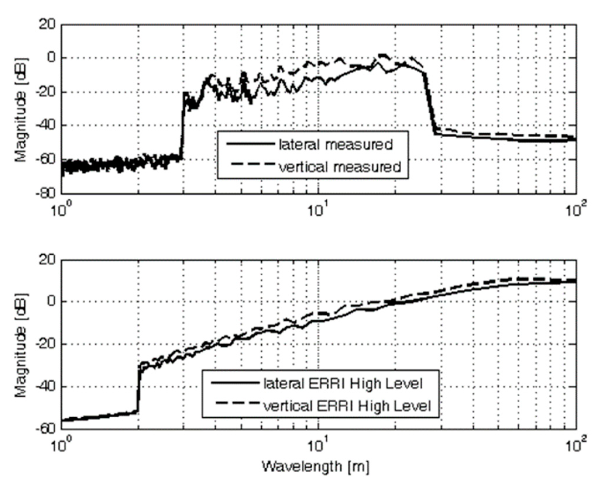
Figure 9.
Comparison of the PSD functions for lateral and vertical irregularities in the case of real measurements (above) and analytical ERRI high level (below).
Lateral forces were therefore evaluated by runs on a 300 m section of track, with irregularities measured from a regional line where running dynamic homologation tests are usually performed according to the requirements of EN14363 [19]. The PSD functions of lateral and vertical irregularities are plotted in Figure 9 and compared with the PSD function of ERRI high-level irregularities [26], which are normally used to analytically model track irregularities in multibody simulations.
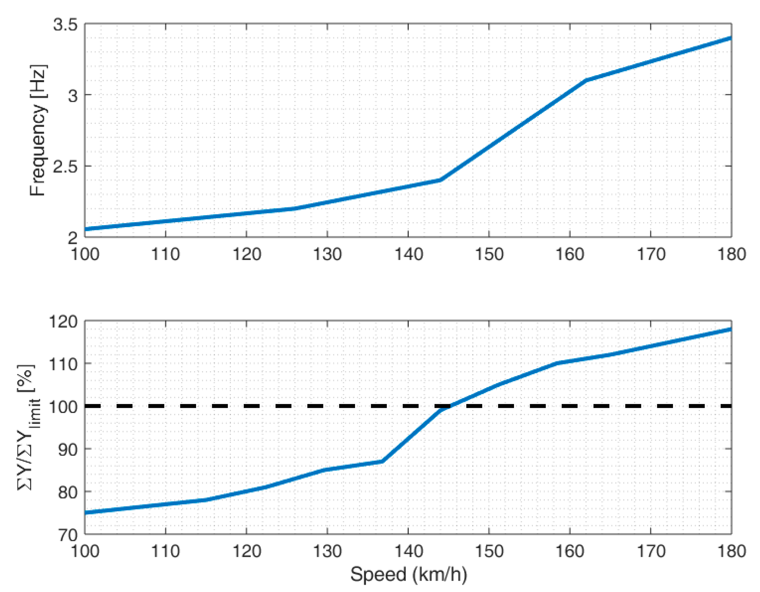
The trailer wheelset of the bogie always shows higher values of lateral force, reaching the limit earlier than the leading one. The maximum RMS value of the trailer wheelset as the percentage of the limit value vs. the running speed is plotted in Figure 10 (below) and compared with the oscillation frequency. A good agreement can be seen between the frequency jump and the increase in lateral force, and the bogie is stable at running speeds of up to 140 km/h.
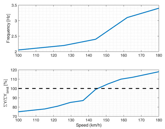
Figure 10.
Results of the stability assessment in empty conditions considering oscillation frequency on ideal track (above) and lateral force on the rear wheelset on defective track with respect to the limit value shown with dashed line (below).
3.2. Vertical Dynamics on Sinusoidal Track Irregularities
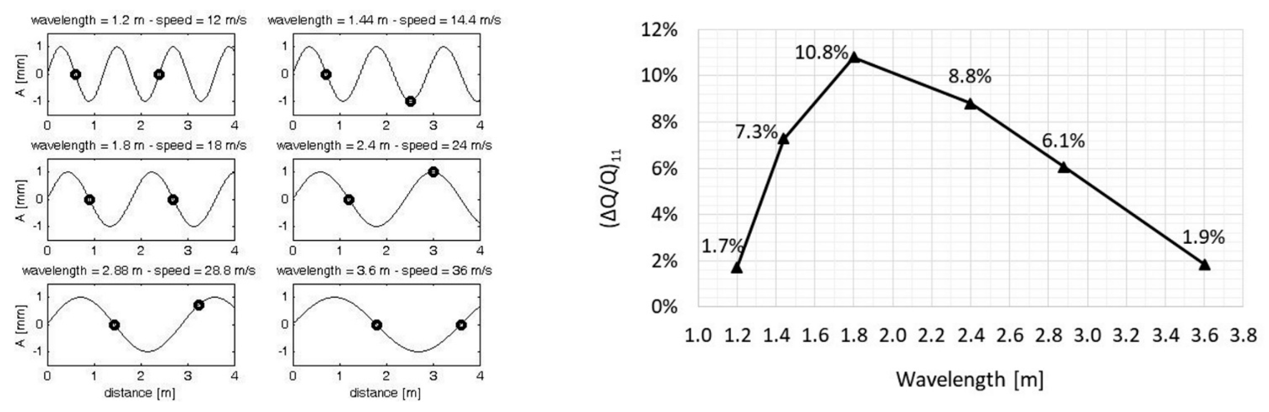
The horizontal suspension arrangement is particularly effective on vertical uneven tracks, without introducing rubber elements or hydraulic dampers. This is particularly true for such irregularities with wavelengths letting the two wheels on the same side move in counter phase, generating a suspension “short-circuit effect” that can equalize the vertical contact force between the front and the rear wheel. This effect is impossible on a conventional suspension system, as the two wheelsets are always free to move independently. This behaviour is evaluated by simulations on a track where sinusoidal defects are modelled. The wavelengths of these irregularities are chosen to let the wheels move in phase, in counter phase and quadrature, while the excitation frequency has been set to 10 Hz to keep a wide range of speed with wavelengths values as close as possible to the bogie wheelbase (1.2 ÷ 3.6 m).
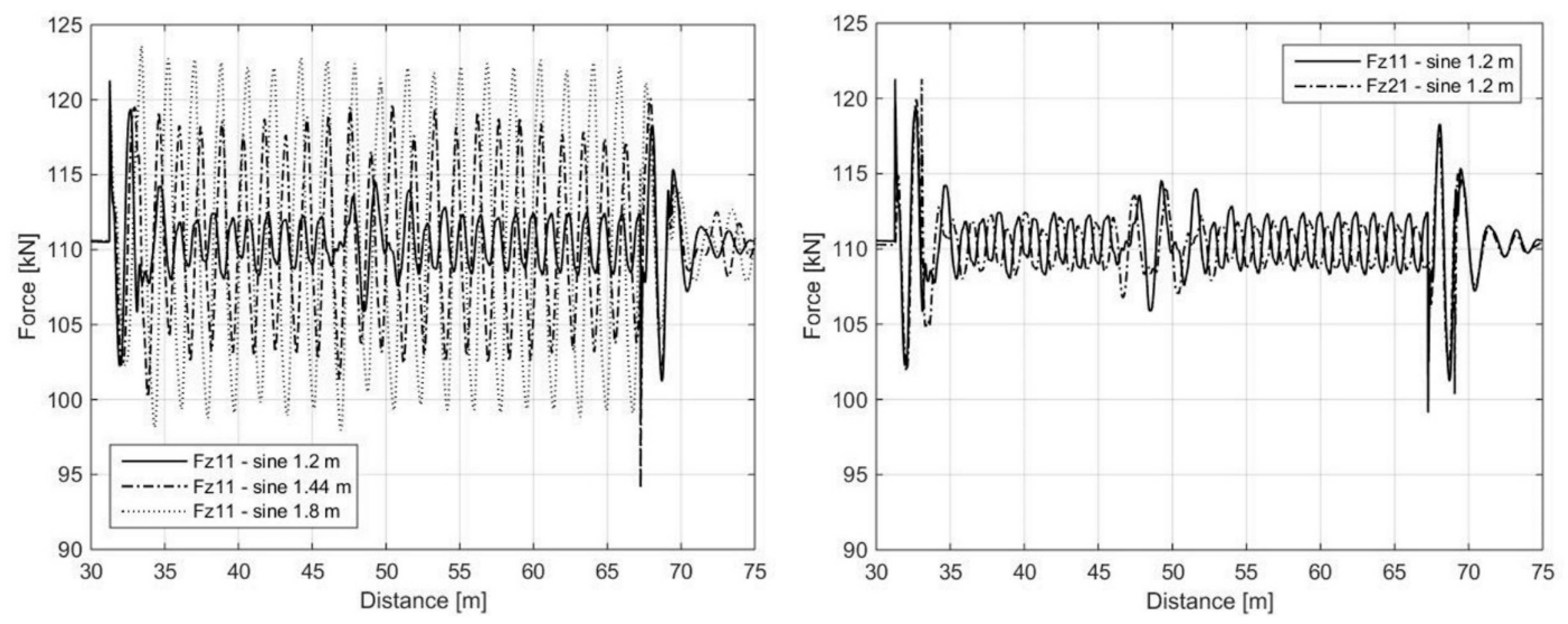
The resulting speeds are from 45 km/h to 130 km/h, and a summary of the set of simulations is shown in Figure 11 (left). The irregularities were in phase on both the rails to obtain an in-plane movement of the vehicle and to avoid cross effect due to twist. All simulations were performed with the wagon in laden condition. To quantify this equalization effect, the value of vertical force after the transient response was used to evaluate the wheel unloading ΔQ/Q of the first wheel for each wavelength of the sinusoidal irregularity. The lower the wheel unloading, the greater the beneficial effect of the suspension arrangement. As shown in Figure 11 (right), for λ = 1.2 m and λ = 3.6 m (wheels on the same side in counterphase), wheel unloading is lower than 2%, as the dynamic vertical force is nearly equalized by the suspension arrangement. The maximum value is instead reached for the wheels moving perfectly in phase (λ = 1.8 m) as the swinging arms act symmetrically on the spring, which reaches the highest displacement and reaction force. The natural equalization offered by the “short-circuit” effect of the suspension is visible in Figure 12, where the vertical contact force of the first wheel running over the uneven track section is plotted for three wavelengths.
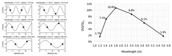
Figure 11.
Summary of the whole set of simulations, where dots represent the bogie wheels (left). Results in terms of wheel unloading of the first right wheelset (right).
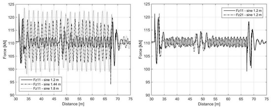
Figure 12.
Detail of the front axle vertical wheel force while running over three different irregularities (left) and comparison between front axle and rear axle vertical wheel force (on the same bogie side).
When the two wheelsets move in counter phase (λ = 1.2 m), the two swinging arms act on the spring in the same direction, and its stationary reaction is zero, resulting in a nearly perfect equalization of the load between the wheels.
3.3. Vertical Dynamics on Random PSD Irregularities
A more general evaluation of the vertical dynamics is described in this paragraph. A part of the Track Access Charge (TAC) for freight vehicles in the UK is due to the vertical wheel dynamic force produced by the wagon. In particular, the parameter used to evaluate the performance of a bogie is the Ride Force Count (RFC). The RFC is a metric of the vertical dynamic force that assesses the track friendliness of freight bogies and their suspension system. From this index, a Suspension Discount Factor (SDF) is then calculated, which scales the final Variable Usage Charge (VUC) paid by operators. The SDF is defined as a function of RFC by a curve (or discrete bands).
RFC values are calculated using dynamic simulations on a track, named Track for Banding (TfB), and evaluating the correlation between the standard deviation of the vertical track irregularities and the standard deviation of the dynamic vertical force, calculated for 200 m long track sections. Using a linear interpolation of the data, it is possible to derive the Ride Force Coefficient (gradient of the trend line in kN/mm) and the Ride Force Constant (intersection of the trend line with the y-axis in kN). Then, these parameters supply the SDF evaluating the distribution of the standard deviation of the vertical irregularities, as described by Network Rail specifications [27].
This method was therefore chosen to evaluate the vertical performance of the new primary suspension arrangement. To compare the results with those from other freight wagons, data available in the literature [28] were used, in which a four-axle Y-series flat 60′ wagon represents the reference for another innovative freight bogie developed for the six-axle Spectrum vehicle project, with a maximum 22.5 t axle load at the centre bogie and 17 t axle load at the outer bogies, a maximum speed of 160 km/h and hydraulically damped primary coil springs. To permit a fair comparison, the vertical forces (low-pass-filtered at 20 Hz) were initially normalized by the axle load. The simulation speed was set to 120 km/h, 145 km/h (empty condition) and 160 km/h (laden condition).
It is worth highlighting that the irregularities of the TfB represent poor-quality lines, and they are based on actual measured data that were not available to the authors. However, ERRI high-level irregularities are in good agreement with that distribution. This is shown in Figure 13, where a track divided into 100 m long sections was simulated, showing that the distribution is very close to TfB and that it can be used for the RFC calculations.
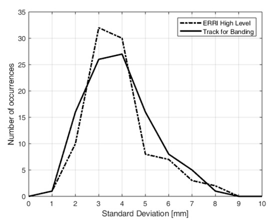
Figure 13.
Number of occurrences of the standard deviation of vertical ERRI high-level defects (dashed line) and the track for banding distribution (solid line).
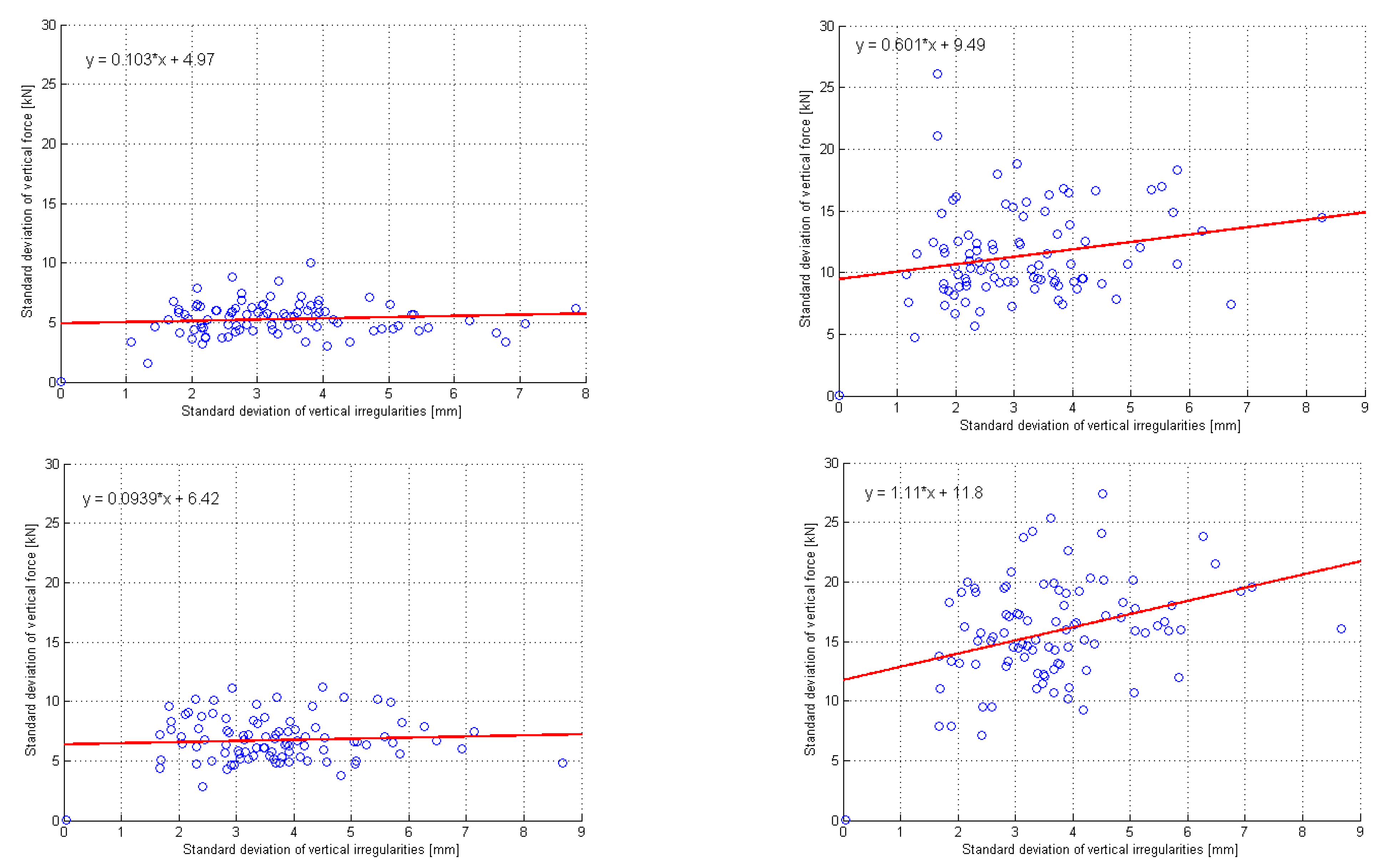
The standard deviation of the dynamic vertical force normalized with respect to the axle load is shown for each track section in Figure 14, while the Ride Force Coefficient and the Ride Force Constant used to perform VUC calculation are shown in Figure 15. The mean value over the track section is the most relevant and directly usable parameter to compare different vehicles, and the advantages of the 4L bogie with respect to Y25 are visible in Table 1. At the maximum speed, the values are only slightly higher than those of the Spectrum vehicle.
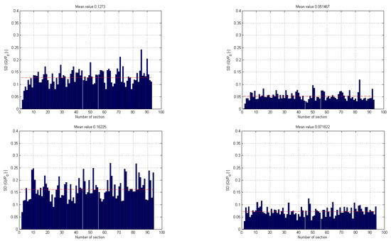
Figure 14.
Standard deviation of the vertical dynamic force over 100 m long track sections for the empty wagon (left) and for the laden wagon (right) at the speed of 120 km/h (above) and of 145 km/h (below). Dashed red lines represent mean values.
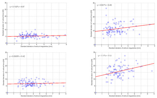
Figure 15.
Standard deviation of the vertical dynamic force over 100 m long track sections for the empty wagon (left) and for the laden wagon (right) plotted against the standard deviation of vertical irregularities at the speed of 120 km/h (above) and of 145 km/h (below). Red lines are the best-fit linear regressions.

Table 1.
Mean values of standard deviation (SD) of dynamic vertical force comparison between bogies. Values are normalized with respect to the axle load.
To perform a VUC calculation for the freight wagons, the SDF was evaluated. This value was obtained separately for the tare and laden conditions from the RFC value, according to (5)
where SD(i) is the i-th standard deviation class (1 mm each) of vertical irregularities, P1 is the Ride Force Coefficient, P2 is the Ride Force Constant and N is the number of occurrences for the i-th class of standard deviation SD(i). The results in terms of the Suspension Discount Factor are shown in Table 2. The values are derived from seven bands (from 0.858 to 1.098), where each band corresponds to a particular range of RFC, different for tare and laden conditions.
Table 2.
Suspension Discount Factor comparison in empty and laden condition.
Y25 bogie has a Discount Factor greater than 1 in both conditions, while the 4L bogie reaches the maximum class only at 160 km/h in laden condition, which is reached by the Spectrum bogie. In empty conditions, the Spectrum bogie performs significantly better than the 4L bogie due to the use of hydraulic damping for the primary suspension.
3.4. Steady State Curving Behaviour
The track friendliness of a vehicle, and therefore of a bogie, is often evaluated using the Tγ value [29]. The product of the tangential force T and the tangential creepage γ is a measure (in J/m) of the energy dissipated at the contact of each wheel used to assess both track friendliness and the steering ability of a bogie. This parameter was also used to compare different types of freight bogies considering their effect on rolling contact fatigue (RCF) [30]. The importance of Tγ as a parameter to evaluate the track access charge of a vehicle is confirmed by its introduction in the track deterioration models [31,32].
The relationship between Tγ and the damage introduced by an axle of the vehicle is described by a Rail Surface Damage model in which two different damage rates are assumed for wear and RCF crack growth. If Tγ ≤ 15 J/m, no damage is introduced in the rail, while if 16 ≤ Tγ ≤ 175 J/m, RCF damage is dominant and can be fixed by grinding. However, when Tγ is over 65 J/m, the wear mechanism contributes to removing surface cracks, and the total damage rate reduces until wear is the only damage on rails (Tγ ≥ 176 J/m). In this case, when the rail reaches the defined side wear limit, rail renewal is necessary. In the next paragraph, only Tγ from high rail is considered.
In the VUC, 85% of the charge is assigned to track maintenance and renewal, 70% is linked to vertical rail forces and 30% to horizontal rail forces. While the first is only a function of axle load, operating speed and unsprung mass, the second depends on the steady-state curving behaviour of the vehicle and therefore on Tγ. The model prescribes several simulations in different radius curves to generate a Tγ table used to calculate the charge for freight or passenger operators.
An automatic tool was developed and included in VI-Rail that generated fifteen curves (from 200 m to 10,000 m) with the conditions described by Network Rail specifications [33]. The curving behaviour was evaluated with a cant deficiency of 40 mm for passenger vehicles, with a cant deficiency of 0 mm (i.e., at the balance speed) for freight vehicles not limited to 72 km/h, and a cant excess of 20 mm for freight vehicles limited to 72 km/h. Therefore, freight vehicle simulations were performed at the equilibrium speed.
It is worth highlighting that the assumption of hd = 0 (anc = 0) is seen as particularly conservative, as running faster is one of the main goals of freight operation. Higher cant deficiency values were therefore investigated. Moreover, due to the roll angle of the wagon, it is believed that the new bogie generates better steering performance, as it allows the wheelset to align radially when the vehicle runs with hd > 0 (anc > 0).
As the effect of cant deficiency was found not relevant for the empty vehicle, Tγ values and angle-of-attack for the laden condition are only shown in Figure 16 for hd = 0, 40, 92, 153 mm. These values correspond to anc = 0, 0.26, 0.6 (typical for freight traffic) and 1.0 (typical for passenger traffic) m/s2.
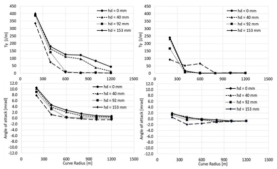
Figure 16.
Tγ (top) and angle of attack (bottom) of front axle (left) and rear axle (right) of the leading bogie for different curve radii and cant deficiency values for the new bogie in laden condition.
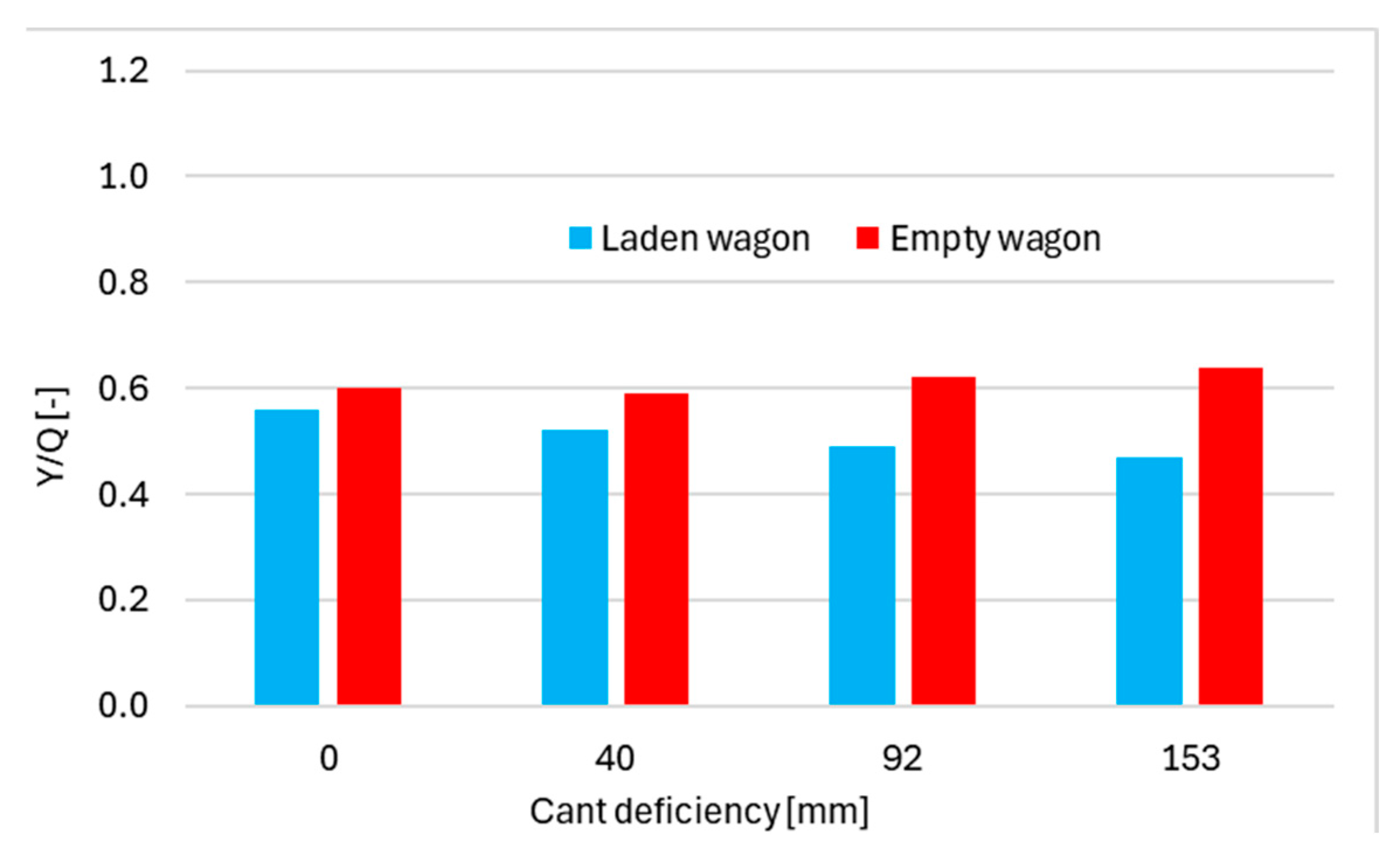
While for low radius curves (200 m), the steering ability is quite poor in all the investigated situations, the effect of increasing the cant deficiency is beneficial for mild curve radii (R = 600 ÷ 800 m) where at the equilibrium speed, the transition between wheel and rail flange contact to tread contact occurs. This transition shifts towards lower curve radii when the cant deficiency increases, as the angle of attack tends to zero more rapidly. For small radius curves, the derailment quotient between the lateral wheel force Y and the vertical wheel force Q is evaluated to ensure the safety conditions are met. This is shown in Figure 17 for a 200 m curve radius.

Figure 17.
Derailment quotient for curve radius R = 200 m and for different cant deficiency values in laden and empty conditions.
The derailment quotient was well below the limit value (Y/Q) = 1.2 in all running conditions with different combination of cant deficiency and loading conditions.
4. Conclusions
In recent years, the necessity to improve the running behaviour of freight wagons has become a crucial topic within the railway industry and research. A survey of current research and market situation shows that lower mass, better ride quality and lower noise emissions seem to be the more pertinent topics for railway operators, together with simple maintenance and improved reliability. An operating speed of 140 km/h (or 160 km/h for low-density goods) is a reasonable target for the bogie of the future. Track friendliness due to self-steering mechanism is quite popular currently, while rubber elements and hydraulic dampers for primary suspension are not very well spread due to maintenance reasons.
A light and compact bogie architecture with inboard bearings and an inside frame is presented. The new bogie can be equipped with both wheel-mounted brake discs or modern tread braking units, further reducing the mass of the bogie.
Lower mass and yaw moment of inertia are key characteristics to improve the steering ability at sharp curves while maintaining good stability on straight tracks. Therefore, multibody simulations were performed to investigate the dynamic behaviour of the vehicle, showing that stability over defective track can be guaranteed up to 140 km/h with empty conditions and high values of equivalent conicity.
Progressive coil springs longitudinally arranged were used in the primary suspension instead of the typical bi-linear elastic characteristic of the Y25 bogie, improving the vertical dynamic behaviour of the bogie. At the maximum speed, vertical dynamic forces over a defective track were still lower than the ones generated by a wagon equipped with the Y25 bogie, reducing the possibility of railhead damage.
The spring arrangement also gave a steering effect for positive non-compensated acceleration, and simulations showed good results in terms of wear reduction, with a remarkable reduction in mild radius curves (R = 600 ÷ 800 m).
Funding
The author received no financial support for the research, authorship, and/or publication of this article.
Data Availability Statement
Data used for this study are publicly available.
Conflicts of Interest
The author declares no potential conflicts of interest with respect to the research, authorship, and/or publication of this article.
List of Symbols
| Symbol | Description | Physical Unit |
| Tγ | Wear number at the wheel rail contact | J/m |
| K | Stiffness of the primary suspension | N/m |
| Q | Vertical wheel load | N |
| g | Gravitational acceleration | m/s2 |
| ΔQ | Variation of the wheel vertical load | N |
| Fz | Vertical load on the centre bowl of the bogie | N |
| a | Longitudinal length of the swinging arm | m |
| b | Vertical length of the swinging arm | m |
| X | Yaw resistance of the bogie | - |
| Mz | Frictional torque around the vertical axis | N/m |
| 2a+ | Bogie wheelbase | m |
| P0 | Vertical axle load | N |
| L | Wavelength of Klingel motion | m |
| R | Wheel radius | m |
| s | Distance between rolling radius circles | m |
| γ | Conicity of the wheels | - |
| γeq | Equivalent conicity for actual wheel/rail contact | - |
| f0 | Instability frequency | Hz |
| ΣY | Sum of the guiding (lateral) wheelset forces | N |
| λ | Wavelength of irregularities | m |
| P1 | Ride force coefficient | kN/mm |
| P2 | Ride force constant | kN |
| hd | Cant deficiency | mm |
| anc * | Non-compensated acceleration | m/s2 |
| Y | Guiding (lateral) wheel load | N |
| Y/Q | Derailment quotient | - |
| * Cant deficiency and non-compensated acceleration are related by the equation anc = hd(g/s) | ||
References
- Hecht, M. European freight vehicle running gear: Today’s position and future demands. Proc. Inst. Mech. Eng. Part F J. Rail Rapid Transit 2001, 215, 1–11. [Google Scholar] [CrossRef]
- Iwnicki, S.D.; Stichel, S.; Orlova, A.; Hecht, M. Dynamics of railway freight vehicles. Veh. Syst. Dyn. 2015, 53, 995–1033. [Google Scholar] [CrossRef]
- SUSTRAIL Project. Concluding Technical Report. Available online: www.sustrail.eu/IMG/pdf/sustrail_final_book_web.pdf (accessed on 15 May 2024).
- 5L Project. White Paper Innovative Rail Freight Wagon 2030. Available online: https://www.schienenfzg.tu-berlin.de/fileadmin/fg62/pdf/White_Paper_Innovative_Rail_Freight_Wagon_2030_01.pdf (accessed on 15 May 2024).
- Greenbrier Europe. Products Catalogue. Available online: https://www.greenbrier-europe.com/products/product/ (accessed on 15 May 2024).
- Scoldan, D.; Gabriel, N.; Kik, W. RC25NT—A new track friendly bogie for the heavy freight transport. ZEVrail Glas. Ann. 2011, 135, 252–260. [Google Scholar]
- Tatravagonka Poprad. Track-Friendly Bogies. Available online: https://tatravagonka.sk/bogies_tax/track-friendly-bogies/?lang=en (accessed on 15 May 2024).
- TF25 Bogie. Available online: https://railway-news.com/download/wabtec-axiom-tf25-bogie-family/ (accessed on 15 May 2024).
- DRRS Bogie. Available online: https://www.railwaypro.com/wp/drrsss-y-bogie-for-rapid-freight-trains-in-germany/ (accessed on 15 May 2024).
- Searancke, E.J. The B5000 bogie development. In Wheels and Axles Cost-Effective Engineering; IMechE Seminar Publication; Wiley: Hoboken, NJ, USA, 2000. [Google Scholar]
- Hecht, M. Wear and energy-saving freight bogie designs with rubber primary springs: Principles and experiences. Proc. Inst. Mech. Eng. Part F J. Rail Rapid Transit 2009, 227, 105–110. [Google Scholar] [CrossRef]
- Bracciali, A.; Megna, G. Contact mechanics issues of a vehicle equipped with partially independently rotating wheelsets. Wear 2016, 366–367, 233–240. [Google Scholar] [CrossRef]
- Ihme, J. Schienenfahrzeugtechnik; Springer: Berlin/Heidelberg, Germany, 2016; pp. 183–184. [Google Scholar]
- EN 13749:2021+A1:2023; Railway Applications—Wheelsets and Bogies—Method of Specifying the Structural Requirements of Bogie Frames. The European Committee for Standardization (CEN): Brussels, Belgium, 2023.
- DVS1612:2014; Design and Endurance Strength Analysis of Steel Welded Joints in Rail-Vehicle Construction. German Welding Society: Düsseldorf, Germany, 2014.
- Vi-Grade Engineering Software & Service; Vi-Rail 18.0 Documentation; Vi-Grade GmbH: Darmstadt, Germany, 2017.
- EN16235:2023; Railway Application—Testing for the Acceptance of Running Characteristics of Railway Vehicles—Freight Wagons—Conditions for Dispensation of Freight Wagons with Defined Characteristics from on-Track Tests according to EN 14363. The European Committee for Standardization (CEN): Brussels, Belgium, 2023.
- TENMAT. Advance Materials. Available online: https://www.tenmat.com/wear-parts-bearings/rail/ (accessed on 15 May 2024).
- EN 14363:2016+A2:2022; Railway Applications—Testing and Simulation for the Acceptance of Running Characteristics of Railway Vehicles—Running Behaviour and Stationary Tests. The European Committee for Standardization (CEN): Brussels, Belgium, 2022.
- Iwnicki, S. The results of Manchester benchmark. In The Manchester Benchmarks for Rail Vehicle Simulations, 1st ed.; Iwnicki, S., Ed.; Tailor & Francis: New York, NY, USA, 1999; pp. 2–12. [Google Scholar]
- True, H. Multiple attractors and critical parameters and how to find them numerically: The right, the wrong and the gambling way. Veh. Syst. Dyn. 2013, 51, 443–459. [Google Scholar] [CrossRef]
- Krishna, V.V.; Casanueva, C.; Hossein-Nia, S.; Stichel, S. FR8RAIL Y25 running gear for high tonnage and speed. In Proceedings of the International Heavy Haul Association Sts Conference (IHHA 2019), Narvik, Norway, 12–14 June 2019. [Google Scholar]
- Molatefi, H.; Hecht, M.; Kadivar, M.H. Critical speed and limit cycles in the empty Y25-freight wagon. Proc. Inst. Mech. Eng. Part F J. Rail Rapid Transit 2006, 220, 347–359. [Google Scholar] [CrossRef]
- EN 15302:2021; Wheel-Rail Contact Geometry Parameters—Definitions and Methods for Evaluation. The European Committee for Standardization (CEN): Brussels, Belgium, 2021.
- CEN/TR 17039; Railway Applications—Technical Report about the Revision of EN 14363. The European Committee for Standardization (CEN): Brussels, Belgium, 2017.
- ERRI B176 RP1; Bogies with Steered or Steering Wheelsets, Report No. 1, Specifications and Preliminary Studies, Volume 2, Specifications for a Bogie with Improved Curving Characteristics. Office for Research and Experiments of the International Union of Railways: Utrecht, The Nederland, 1989.
- Network Rail. RFCpro Workshop. Available online: https://www.networkrail.co.uk/wp-content/uploads/2017/02/RFCpro-workshop-slides.pdf (accessed on 15 May 2024).
- Shackleton, P.; Bezin, Y.; Crosbee, D. Development of a new running gear for the Spectrum intermodal vehicle. In The Dynamics of Vehicles on Roads and Tracks, 1st ed.; Rosenberger, M., Plöchl, M., Six, K., Edelmann, J., Eds.; CRC Press: London, UK, 2016. [Google Scholar]
- Megna, G.; Bracciali, A. Gearless Track-Friendly Metro with Guided Independently Rotating Wheels. Urban Rail Transit 2021, 7, 285–300. [Google Scholar] [CrossRef]
- Tunna, J.; Urban, C. A parametric study of the effects of freight vehicles on rolling contact fatigue of rail. Proc. Inst. Mech. Eng. Part F J. Rail Rapid Transit 2009, 223, 141–151. [Google Scholar] [CrossRef]
- Burstow, M. Whole Life Rail Model Application and Development for RSSB—Development of an RCF Damage Parameter; Rail Safety & Standards Board: London, UK, 2003. [Google Scholar]
- Öberg, J.; Andersson, E. Determining Deterioration Cost for Railway Tracks. Proc. Inst. Mech. Eng. Part F J. Rail Rapid Transit 2009, 223, 121–129. [Google Scholar] [CrossRef]
- Network Rail. VTAC Calculator: Guidance Note for Determining Tγ Values. Available online: https://www.networkrail.co.uk/wp-content/uploads/2016/12/VTAC-calculator-Guidance-note-for-determining-Tgamma-values.pdf (accessed on 15 May 2024).


Disclaimer/Publisher’s Note: The statements, opinions and data contained in all publications are solely those of the individual author(s) and contributor(s) and not of MDPI and/or the editor(s). MDPI and/or the editor(s) disclaim responsibility for any injury to people or property resulting from any ideas, methods, instructions or products referred to in the content. |
© 2024 by the author. Licensee MDPI, Basel, Switzerland. This article is an open access article distributed under the terms and conditions of the Creative Commons Attribution (CC BY) license (https://creativecommons.org/licenses/by/4.0/).