
Understanding the Effect of Material Parameters on the Processability of Injection-Molded Thermoset-Based Bonded Magnets


Abstract
:
1. Introduction
1.1. Magnetic Properties
1.2. Injection Molding
1.3. Flow Behaviour and Reaction Kinetics of Thermosets
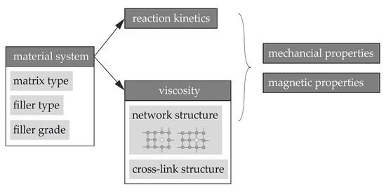
1.4. Aim of the Paper
2. Materials and Methods
2.1. Material
2.2. Fabrication of the Test Specimens
2.3. Characterization
2.3.1. Differential Scanning Calorimetry (DSC) According to DIN EN ISO 11357
2.3.2. Determination of the Viscosity Using a Rotational Viscometer According to DIN EN 6043
2.3.3. Mechanical Properties according to DIN EN ISO 527
2.3.4. Magnetic Properties
2.3.5. Filler Orientation
3. Results and Discussion
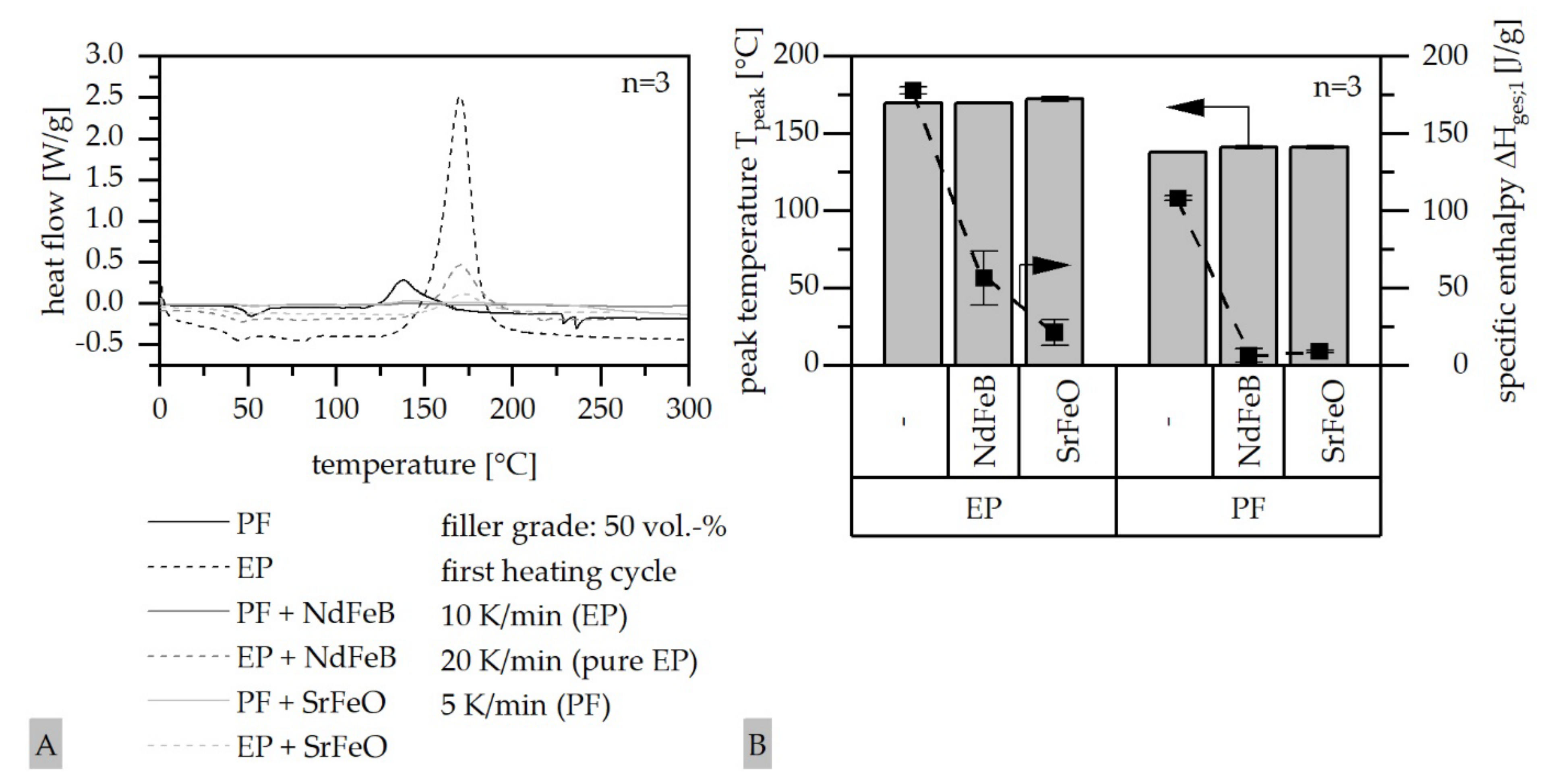
3.1. Differential Scanning Calorimetry (DSC)
3.2. Change of the Viscosity Relative to Matrix, Filler and Filler Amount
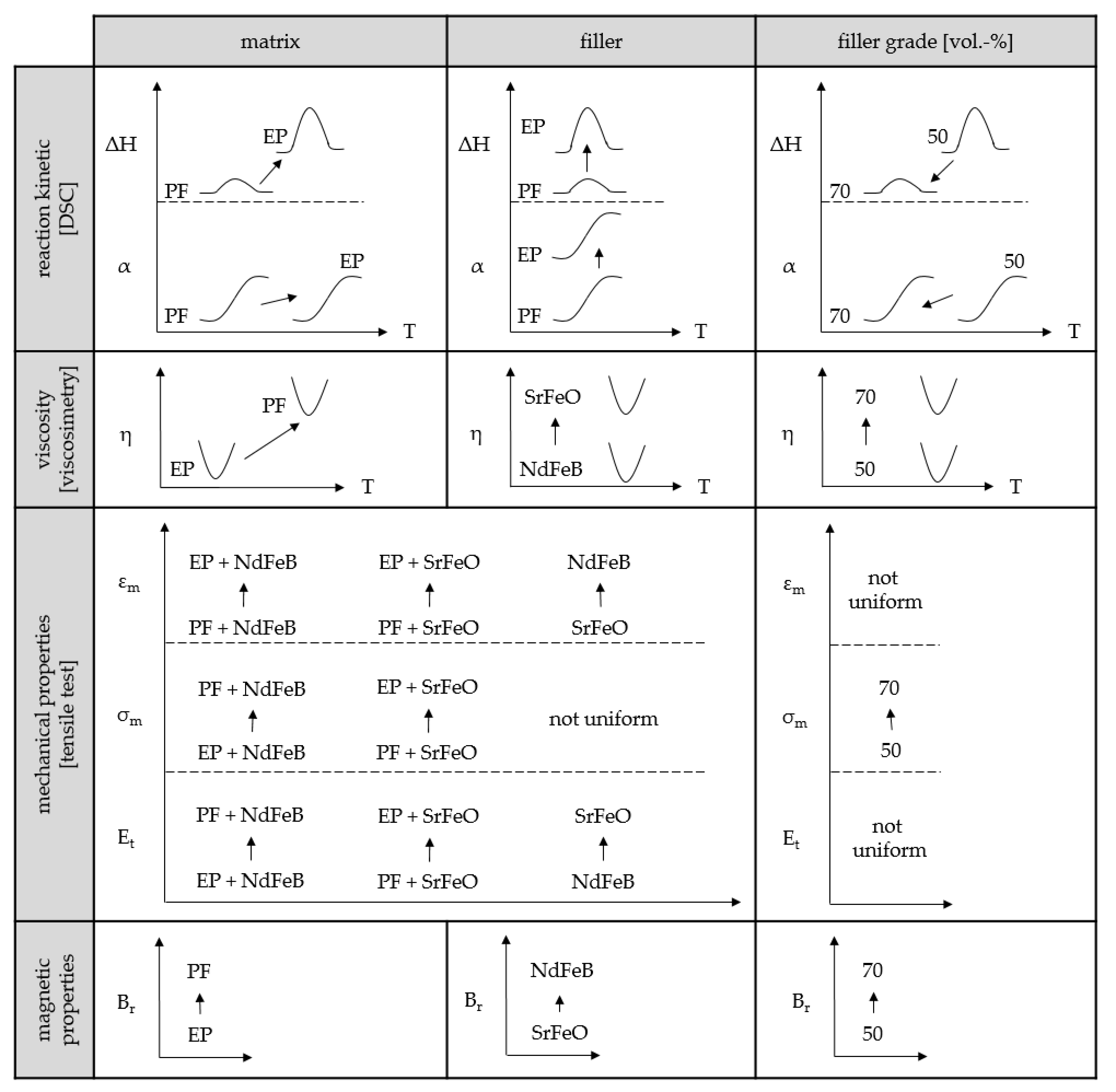
3.3. Influence of the Reaction Kinetics and the Viscosity on the Mechanical Properties Relative to the Material System
3.4. Influence of the Reaction Kinetics and the Viscosity on the Magnetic Properties Relative to the Material System
4. Conclusions
Author Contributions
Funding
Data Availability Statement
Acknowledgments
Conflicts of Interest
References
- Cassing, W.; Seitz, D. Dauermagnete: Mess- und Magnetisierungstechnik, 2nd ed.; Expert-Verlag: Renningen, Germany, 2015. [Google Scholar]
- Drummer, D. Prozessführung beim Spritzgießen kunststoffgebundener Dauermagnete. In Kunststoffgebundene Dauermagnete; Springer VDI: Düsseldorf, Germany, 2004. [Google Scholar]
- Johannaber, F.; Michaeli, W. Handbuch Spritzgießen, 2nd ed.; Hanser: München, Germany, 2004. [Google Scholar]
- Ormerod, J.; Constantinides, S. Bonded permanent magnets: Current status and future opportunities (invited). J. Appl. Phys. 1997, 81, 4816–4820. [Google Scholar] [CrossRef] [Green Version]
- Reppel, G.W. Duroplastgepresste Magnete—Werkstoffe, Verfahren und Eigenschaften. In Kunststoffgebundene Dauermagnete; Springer VDI: Düsseldorf, Germany, 2004; pp. 14–36. [Google Scholar]
- Lagorce, L.; Allen, M. Magnetic and mechanical properties of micromachined strontium ferrite/polyimide composites. J. Microelectromechanical Syst. 1997, 6, 307–312. [Google Scholar] [CrossRef] [Green Version]
- Kurth, K.H.; Drummer, D. Influences on the Magnetic Properties of Injection Molded Multipolar Rings. Int. Polym. Process. 2016, 31, 356–363. [Google Scholar] [CrossRef]
- MS–Schramberg GmbH & Co. KG. 2010. Available online: https://www.magnete.de/de.html (accessed on 26 October 2021).
- Hagemann, B. Kunststoffgebundene Magnete in der Antriebstechnik—Möglichkeiten und Grenzen. In Kunststoffgebundene Dauermagnete; Springer VDI: Düsseldorf, Germany, 2004. [Google Scholar]
- Baur, E.; Brinkmann, S.; Osswald, T.; Rudolph, N.E. Schmachtenberg, Saechtling Kunststoff Taschenbuch, 31st ed.; Carl Hanser Verlag: München, Germany, 2013. [Google Scholar]
- Baran, W. Magnetische Werkstoffe für Energiewandler und Statistische Systeme. In Magnetische Werkstoffe; Verlag TÜV: Rheinland, Germany, 1990. [Google Scholar]
- Michalowsky, L. Magnettechnik: Grundlagen, Werkstoffe, Anwendungen, 3rd ed.; Vulkan-Verlag: Essen, Germany, 2006. [Google Scholar]
- Wellmann, P. Materialien der Elektronik und Energietechnik: Halbleiter, Graphen, Funktionale Materialien; Springer Fachmedien Wiesbaden: Wiesbaden, Germany, 2017. [Google Scholar]
- Hering, E.; Martin, R.; Stohrer, M. Physik für Ingenieure, 12th ed.; Springer Vieweg: Berlin, Germany, 2016. [Google Scholar]
- Koch, J. Dauermagentische Werkstoffe und ihre Anwendungen. Physikalische Blätter 1975, 31, 439–455. [Google Scholar] [CrossRef]
- Drummer, D. Verarbeitung und Eigenschaften Kunststoffgebundener Dauermagnete. Dissertation. Ph.D. Thesis, Universität Erlangen-Nürnberg: Lehrstuhl für Kunststofftechnik, Erlangen, Germany, 2004. [Google Scholar]
- Ma, B.; Sun, A.; Gao, X.; Bao, X.; Li, J.; Lang, H. Preparation of anisotropic bonded NdFeB/SmFeN hybrid magnets by mixing two different size powders. J. Magn. Magn. Mater. 2018, 457, 70–74. [Google Scholar] [CrossRef]
- Stitz, S.; Keller, W. Spritzgießtechnik: Verarbeitung, Maschine, Peripherie, 2nd ed.; Hanser: München, Germany, 2004. [Google Scholar]
- Kurth, K.H.; Drummer, D. Variation of the Pole Length in Pole-Oriented Bonded Rings due to the Location and Number of Injection Points. J. Polym. 2017, 2017, 8241859. [Google Scholar] [CrossRef] [Green Version]
- Hoven-Nievelstein, W. Wir bewegen uns in Richtung Spezialitäten, Kunststoffe—Werkstoffe, Verarbeitung. Anwendung 2008, 6, 24–29. [Google Scholar]
- Altmann, N.; Halley, P.J.; Cooper-White, J.; Lange, J. The effects of slica fillers on the gelation and viltrification of highly filled epoxy-amine thermosets. Macromol. Symp. 2001, 169, 171–177. [Google Scholar] [CrossRef]
- Bae, J.; Jang, J.; Yoon, S.-H. Cure Behavior of the Liquid-Crystalline Epoxy/Carbon Nanotube System and the Effect of Surface Treatment of Carbon Fillers on Cure Reaction. Macromol. Chem. Phys. 2002, 203, 2196–2204. [Google Scholar] [CrossRef]
- Dutta, A.; Ryan, M. Effect of fillers on kinetics of epoxy cure. J. Appl. Polym. Sci. 1979, 24, 635–649. [Google Scholar] [CrossRef]
- Wang, X.; Jin, J.; Song, M.; Lin, Y. Effect of graphene oxide sheet size on the curing kinetics and thermal stability of epoxy resins. Mater. Res. Express 2016, 3, 105303. [Google Scholar] [CrossRef] [Green Version]
- Halley, P.J. A new chemorheological analysis of highly filled thermosets used in integrated circuit packaging. J. Appl. Polym. Sci. 1997, 64, 95–106. [Google Scholar] [CrossRef]
- Altmann, N.; Halley, P.J. The effect of follers on the chemorheology of highly filled eopxy resin: I. Effects on cure transitions and kinetics. Polym. Int. 2003, 52, 113–119. [Google Scholar] [CrossRef]
- Zhao, Z.; Zhanyu, Z.; Drummer, D. Thermal conductivity of alumininosilicate and aluminium oxide filled thermosets for injection molding. Polymers 2018, 10, 457. [Google Scholar] [CrossRef] [PubMed] [Green Version]
- Zhao, Y.; Drummer, D. Influence of Filler Content and Filler Size on the Curing Kinetics of an Epoxy Resin. Polymers 2019, 11, 1797. [Google Scholar] [CrossRef] [PubMed] [Green Version]
- Yushanov, S.P.; Isayev, A.I.; Levin, V.Y. Perolation simulation of the network degradation during ultrasonic devulcanization. J. Polym. Sci. Part B Polym. Phys. 1996, 34, 2409–2418. [Google Scholar] [CrossRef]
- Rösel, U.; Drummer, D. Correlation between the Flow and Curing Behavior of Hard Magnetic Fillers in Thermosets and the Magnetic Properties. Magnetism 2021, 1, 37–57. [Google Scholar] [CrossRef]
- Maenz, T.; Hülder, G.; Gehde, M. Influence of flow behavor of different matrix materials on the orientation of anisotropic magnetic particles during injection molding. AIP Conf. Proc. 2016, 1779, 20011. [Google Scholar]
- Ehrenstein, G.W.; Riedel, G.; Trawiel, P. Praxis der Thermischen Analyse von Kunststoffen, 2nd ed.; Carl Hanser Verlag: München, Germany, 2003. [Google Scholar]
- DIN EN ISO 11357-5; Kunststoffe—Dynamische Differenz Thermoanalyse (DSC): Teil 5: Bestimmung von Charakteristischen Reaktionstemperaturen und -Zeiten, Reaktionsenthalpie und Umsatz; Deutsche Fassung EN ISO 11357-5:2013. 2014.
- Englich, S. Strukturbildung bei der Verarbeitung von Glasfasergefüllten Phenolformaldehydharzformmassen. Ph.D. Thesis, Technische Universität Chemnitz, Chemnitz, Germany, 2015. [Google Scholar]
- Becker, G.W.; Braun, D. (Eds.) Kunststoff Handbuch: Duroplaste, 2nd ed.; Hanser: München, Germany, 1988. [Google Scholar]
- Batzer, H. (Ed.) Polymere Werkstoffe: Chemie und Physik; Georg Thieme Verlag: Stuttgart, Germany, 1985. [Google Scholar]


| Matrix Material | Density (g/cm³) | Heat Capacity c (J/(g∙K)) | E-Modulus (GPa) | Tensile Strength (MPa) |
|---|---|---|---|---|
| Epoxy resin (EP) | 1.2250 | 1.616 | 13 ± 1 | 70 ± 10 |
| Phenolic resin (PF) | 1.2256 | 1.294 | 18 ± 2 | 130 ± 10 |
| Filler Material | Isotropy | Type | Mean Particle Size (µm) | Density (g/cm³) | Thermal Conductivity λ (W/(m∙K)) | Heat Capacity c (J/(g∙K)) | |
|---|---|---|---|---|---|---|---|
| n | v | ||||||
| SrFeO | Anisotropic | OP71 | 4.87 | 1.94 | 5.38 | 2.3 | 0.639 |
| NdFeB | Isotropic | MQB + | 94.42 | 4.30 | 7.63 | 6.1 | 0.448 |
| Mass temperature | 85 °C |
| Mold temperature | 180–200 °C |
| Holding pressure | 250 bar |
| Heating time | 300 s (EP); 120 s (PF) |
| Injection speed | 15 mm/s |
| Parameter | Influencing Factor | Cause | ||
|---|---|---|---|---|
| matrix | filler | filler grade | ||
| Specific enthalpy ΔHges;1 | ++ | + | + | Heat capacity c of the matrix; thermal conductivity λ of the filler |
| Seak temperature Tpeak | ++ | 0 | 0 | Heat capacity c of the matrix |
| Reaction turnover α | ++ | ++ | + | Heat capacity c and coupling of the matrix; thermal conductivity λ of the filler |
| Parameter | Influencing Factor | Cause | ||
|---|---|---|---|---|
| matrix | filler | filler grade | ||
| Minimum of viscosity ηmin | + | ++ | ++ | Network structure |
| Time at the turning point ttp | + | + | ------- | Cross-link density φlink and structure |
Publisher’s Note: MDPI stays neutral with regard to jurisdictional claims in published maps and institutional affiliations. |
© 2022 by the authors. Licensee MDPI, Basel, Switzerland. This article is an open access article distributed under the terms and conditions of the Creative Commons Attribution (CC BY) license (https://creativecommons.org/licenses/by/4.0/).
Share and Cite
Rösel, U.; Drummer, D. Understanding the Effect of Material Parameters on the Processability of Injection-Molded Thermoset-Based Bonded Magnets. Magnetism 2022, 2, 211-228. https://doi.org/10.3390/magnetism2030016
Rösel U, Drummer D. Understanding the Effect of Material Parameters on the Processability of Injection-Molded Thermoset-Based Bonded Magnets. Magnetism. 2022; 2(3):211-228. https://doi.org/10.3390/magnetism2030016
Chicago/Turabian StyleRösel, Uta, and Dietmar Drummer. 2022. "Understanding the Effect of Material Parameters on the Processability of Injection-Molded Thermoset-Based Bonded Magnets" Magnetism 2, no. 3: 211-228. https://doi.org/10.3390/magnetism2030016
APA StyleRösel, U., & Drummer, D. (2022). Understanding the Effect of Material Parameters on the Processability of Injection-Molded Thermoset-Based Bonded Magnets. Magnetism, 2(3), 211-228. https://doi.org/10.3390/magnetism2030016