Abstract
This work describes an automated pilot plant for the extraction of rare-earth (RE) permanent magnets from computer hard-disk drives (HDDs), demonstrating a commercially viable way to exploit these abundant sources of end-of-life (EOL) magnets. A mobile approach is provided for the on-site destruction of the HDDs in server farms, in compliance with the European Data Protection Regulation (GDPR), enabling both separation of the magnets and automated shredding of the data carrier. This fully automated process identifies (both optically and magnetically) the location of the rare-earth magnets and cuts off the corner of the hard drive containing the rare-earth material in the voice coil motor. This allows for a significant reduction in magnet extraction time (6 s per HDD) compared to previously reported semi-automated (2 min) and manual (5 min) dismantling times. This work will also help to transfer the experience gained in the mobile pilot plant to other future sources of EOL materials such as drive motors and mixed electronic scrap.
1. Introduction
Rare earths (REs) are used in permanent magnets, which are crucial to Europe’s successful green and digital transition as they are essential components for electronics, communications, medical equipment, renewable energy, robotics, electric vehicles and aerospace. While the EU is a world leader in the production of electric motors, it is dependent on imports along the value chain for RE magnet materials. As a result, the REs neodymium, praseodymium, dysprosium and terbium have been identified as the most critical raw materials in Europe [1]. To unlock the commercial potential of the RE materials already in circulation, improved recycling technologies are needed [1].
The Hydrogen Processing of Magnetic Scrap (HPMS) route is a technologically and environmentally sound approach to extract and reprocess high-performance RE permanent magnets for Europe’s high-tech applications and green energy conversion [2,3]. The economic success of magnet recycling depends less on the technical feasibility of the downstream recycling process itself than on the main cost driver, the extraction of the magnets from the respective components, which is often hindered by poor designs for recycling [4]. Using advanced technologies such as high-performance sensors, high-throughput analysis and networked handling systems, this work demonstrates the feasibility of the automated dismantling of geometrically diverse scrap sources at TRL 6–7, even if they are not specifically designed for the easy extraction of the permanent magnets.
By integrating these secondary materials as valuable resources, the increasingly circular supply chains will ensure the availability of REs in Europe, reduce the EU’s dependence on foreign monopolies and ultimately bring magnets to the market at a cost advantage compared to magnets based on primary materials.
As part of the preparatory work, more than 180 applications from various industries (e.g., waste electrical and electronic equipment (WEEE), industrial motors, generators, pumps, loudspeakers, sensors, household appliances and automotive components) were manually disassembled and tested for their magnetic content. Based on a tailored set of parameters [5], the most promising applications for recycling permanent magnets in a circular economy were selected for the development of the automated disassembly processes.
One such identified source of scrap is the voice coil magnet of computer hard-disk drives. The current number of HDDs available for recycling in the EU is estimated to be in the region of 50 million HDDs per year [6]. This implies that there is a potential to recycle approximately 500 tonnes of NdFeB from HDDs in Europe. Estimates of the number of HDDs available in the future depend on several trends occurring simultaneously. While HDDs have largely been replaced by Solid-State Drives (SDDs) in consumer applications, HDD storage is still cheaper per TB than SSD storage. According to industry-sponsored data reports [7,8,9,10], by 2025, more than 175 zettabytes (ZB) of data will be stored in data centres worldwide, driven by the continued growth of applications in analytics, artificial intelligence and deep learning, in addition to the increasing number of IoT devices. To support this vast amount of data, approximately 12.5 billion hard drives would be required based on current technology. However, forecasts indicate that the storage capacity will need to be distributed across all media types, with roughly 59% of that capacity provided by the HDD industry [9]. Given an average hard drive lifespan of two years and ten months [11], leading data centres are expected to operate on a two-year refresh cycle, resulting in the disposal of approximately 3.7 billion HDDs annually. With each HDD containing an average of 10 to 15 g of magnets [12,13], this would generate an end-of-life (EOL) magnet source of 37,000 to 54,000 tonnes per year globally. However, to ensure compliance with the requirements of the European Data Protection Regulation (GDPR) [14], they are not included in the normal waste stream but are destroyed on-site in specialised recycling facilities or in bespoke mobile shredding units. This well-controlled recycling process generally results in a much better collection rate for EOL hard drives in data centres than for consumer electronics [6].
Each HDD contains two RE magnets: a polymer-bonded magnet for the spindle motor that spins the disc and two sintered magnets for the voice coil that control the read arm (Figure 1). As the spindle motor magnet is polymer bonded, the recycling process is complex and has a low yield. As it also contains little magnetic material due to its small size, this work focuses on extracting the commercially much more interesting voice coil magnet for further recycling using the HPMS process.

Figure 1.
HDD without the top lid, where the location of the magnets indicated with red arrows. The voice coils magnet is located in the top left corner and the spindle motor magnet is located in the centre right.
The aim of this work was to develop a fast, reliable and mobile process for extracting the magnets from the hard-disk drive, prior to shredding, in order to make them available for commercially viable recycling. The fully automated process presented identifies and cuts off the corner of the HDD containing the voice coil magnet. This allows for a significant reduction in the magnet extraction time (6 s per HDD) compared to previously reported semi-automated [15] (2 min) and manual (5 min) dismantling times.
2. Materials and Methods
2.1. Magnetic Scanner Section
To determine the position of the magnet inside a hard-disk drive, a magnetic sensor array was constructed by mounting several 3-axis magnetometers in a row on a printed circuit board (PCB), as shown in Figure 2 (left). The magnetic field strength at the surface of a magnet containing scrap objects typically varies across a wide range of 0.01–100 mT. To cover such a wide range of magnetic fields, the sensor board was equipped with two parallel rows of two different types of magnetometers, one row of higher sensitivity/lower range 3-axis Anisotropic Magneto Resistance (AMR) sensors (Memsic MMC5983) and one row of lower sensitivity/higher range 3-axis Hall sensors (AKM AK09970N). The sensor-to-sensor spacing in each row was 5 mm and each PCB contained 24 AMR and 24 Hall sensors.
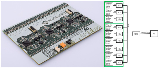
Figure 2.
Sensor PCB (left) and schematic drawing of the digital interface controlling 3 magnetic sensor PCBs (right), which are placed underneath a conveyor belt (see also Figure 3).
The scanner was equipped with 3 sensor boards arranged side by side. The magnetic scanner thus had a total of 72 + 72 magnetometers and covered a total belt width of 335 mm. The sensor sampling rate was 80 Hz, which, for a conveyor belt moving at 30 cm/s, results in a spatial resolution of the magnetic image of 3.75 mm in the direction of belt travel. The magnetic sensors were calibrated in a 3-axis Helmholtz coil prior to installation under the conveyor to determine the individual magnetic sensor gain and offset values.
The sensor arrays were controlled through digital communication from a PC to the on-board microcontrollers and the resulting measurement data were returned using Ethernet UDP communications. The sampled sensor data from the AMR and Hall sensors were merged into a single magnetic image, selecting data from the AMR sensors that were below a threshold magnetic field strength (500 µT) and from the Hall sensors that were above this limit. The magnetometer PCBs were mounted approximately 5 mm below the conveyor belt, with the sensor rows perpendicular to the direction of belt travel. The conveyor belt (Easy Systems Svenska AB) was 200 cm long and 60 cm wide and ran at an adjustable speed in the range of 0 to 50 cm/s. The magnetic sensor array, in combination with the conveyor belt, forms a magnetic scanner, which is capable of generating sequential images of passing objects. The image is created by combining each line of recorded data as the object passes the magnetic sensor array.
The scanner unit (Figure 3) was equipped with a camera (Basler aca2040-55UC) and a light dome (Advanced Illumination DL071) to provide illumination across the scanned objects and minimise light scattering of uneven surfaces. An optical line detector (SICK HLG2) was used to detect an incoming object and trigger the measurement and object analysis routine. The trigger was also used to synchronise the scanner and the robot, which subsequently manipulates the object and positions it in a cutting operation.
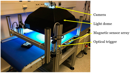
Figure 3.
Magnetic scanner unit.
The magnetic scanner control software was triggered when an object passes an optical line detector. A camera image was captured and analysed by the software (shape, position and rotation). The image and magnetic data were then combined to create a magneto–optical image (Figure 3).
The image acquisition and analysis routine were written in Python using OpenCV, which is an open-source image processing library [16]. The routine that was developed subtracts the background of the image (the conveyor belt) to find the corners of the hard disk in the image.
The magnetic analysis routine was written in LabView. The routine takes the coordinates of the 4 corners and determines whether the shape and size are consistent with the dimensions of a 2.5″ or 3.5″ drive. The corners are then mapped onto the magnetic image and the magnetic field within a circle around each corner is analysed to locate the voice coil corner.
The radius of each analysis circle is set to half of the distance between the shorter sides of the drive. The voice coil corner is identified as the circle containing the largest standard deviation of the magnetic field (Figure 4). For further processing, i.e., the extraction of the magnet-containing voice coil corner from the HDD, the robotic arm receives a message about which corner to cut (see Section 2.2). The results are then displayed and stored for further processing, e.g., statistics or process control, etc. A schematic overview of the magnetic scanner software is shown in Figure 5.
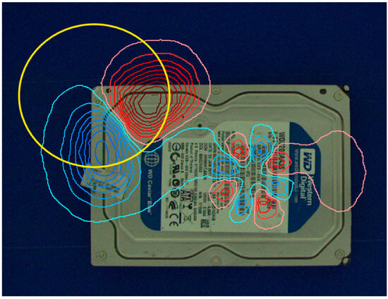
Figure 4.
HDD with a contour plot of the scanned magnetic field superimposed. The plotted magnetic field is the component perpendicular to the conveyor belt, with red lines representing positive (up) field strength and blue negative (down) field strength. The yellow circle marks the identified voice coil corner.
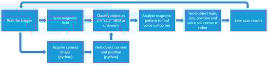
Figure 5.
A schematic overview of the magnetic scanner software written in LabView, except for the camera image acquisition and analysis, which were written in Python.
The focus of the HDD algorithm development was to improve the speed of data analysis. The time to locate the HDD magnetic corner from the image and magnetic data analysis is less than 25 milliseconds. With a typical conveyor belt speed of 30 cm/s, the HDD moves less than 10 mm during corner analysis, making the routine fast enough to match the other processes involved in the HDD pilot.
2.2. Robotic Arm with a HDD Gripping Tool
Following the scanning unit, a Fanuc M-10iA six-axis industrial robot (Figure 6, left) is used together with a pneumatic gripper (Figure 6, right) that is specifically designed to pick up HDDs from both sides regardless of their size (2.5″ or 3.5″). The gripper is capable of handling screws or any minor irregularities in the shape of the disks, but a pre-inspection of the HDDs is recommended to ensure that, for example, frames are removed before they are fed into the system. The robot receives a message via TCP/IP from the magnetic scanner about the type of object being scanned (2.5″ HDD, 3.5″ HDD or other), its position and rotation, and which corner to cut. Since the HDDs are moving on a conveyor belt, the position is given at the time the optical trigger line is broken. Knowing the speed of the conveyor belt, from a wheel encoder mounted on the belt, it is possible to calculate the position as a function of time. The robot picks up the hard drive and delivers the designated corner to the alligator shear cutter.
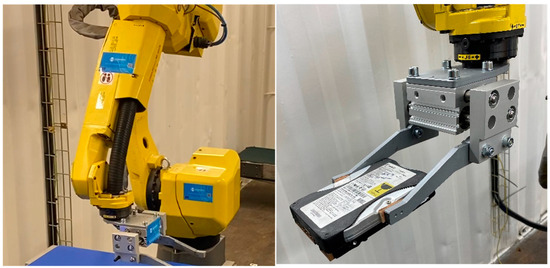
Figure 6.
Fanuc M-10iA industrial robot (left) and tailored pneumatic gripping tool (right).
2.3. Alligator Shear Cutter
The robotic arm feeds the HDD, magnetic corner first, into the gap of an alligator shear cutter (Deltax DTX 310, Figure 7 left). The cutter is equipped with a clamping arm that holds the HDD in place before the shearing force is applied (Figure 7, right). The time it takes to clamp and cut a corner from an HDD is approximately 6 s, which is currently the bottleneck that limits the capacity of the HDD pilot.
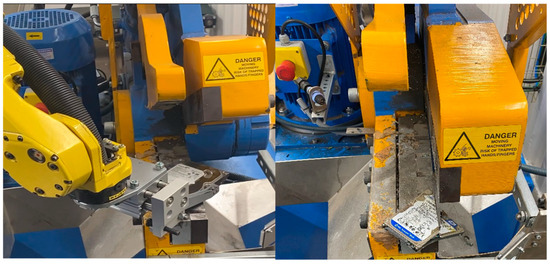
Figure 7.
Robot placing the HDD in the cutter (left) and cutting process (right).
After cutting, a pneumatic system ejects the remaining HDD and simultaneously cleans any residue left on the cutting base. The sheared-off magnetic corners are collected in a container under the cutter for direct HPMS treatment without further processing or disassembly.
2.4. System Integration and Magnet Extraction from HDDs
An automated pilot line for removing magnets from HDDs was built inside a 20 ft container, as shown in Figure 8.
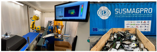
Figure 8.
HDD pilot built inside a 20 ft container (left) and container with processed HDDs in front (right).
The setup consists of the components described above: magnetic scanner, robot with HDD gripper tool, alligator shear cutter and shredder (to be installed). The workflow is illustrated in Figure 9. At the front end of the magnetic scanner is an input gate for HDD feed control. The gate closes when an HDD is detected by the optical trigger. The gate remains closed until the system is ready to process the next disc. This allows the operator to place the next disc on the belt without the risk of jamming the system.
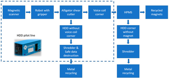
Figure 9.
Workflow chart of the HDD NdFeB magnet harvesting pilot.
The cut corner falls into a separate bin, while the rest of the disc is ejected onto a conveyor belt designed to feed the rest of the disc into a shredder for secure destruction of the stored data. The system is designed to be operated from outside the container for operator safety and is equipped with multiple emergency stops and a physical barrier with opening detection to stop the system immediately in the event of an emergency. A transparent guard has also been provided to prevent any part of the hard drive being projected outwards during the cutting process. The position of the belts and material discharge areas are designed to allow the resulting material to be discharged directly from the container through easily accessible openings.
3. Results
To test the operation, reliability and throughput of the pilot line, 860 kg of discarded HDDs were processed under realistic operating conditions. The pallet (Figure 8, right) contained 605 3.5″ HDDs and 2081 2.5″ HDDs. Approximately 10% of the HDDs received had to be manually pre-processed as they were enclosed in various frames from the PC chassis assembly. The failure to remove protruding items around the disks resulted in the failure of the robot gripper to reliably pick up and hold the disks after scanning.
In some HDD models, the top lid (the side with a printed label) was made from a soft magnetic steel. The magnetic field from the internal disk magnets was distorted by these lids, which made it difficult to locate the voice coil corner from the scanned magnetic image. To avoid this issue, the HDDs were placed facing upwards when feeding the disks into the system.
During the validation phase of the system, a number of failure cases were encountered. The key cases are listed below together with the measures taken to overcome them.
- The alligator shear cutting zone was occasionally obstructed by debris from previously cut HDD fragments. This was handled by adding an actuator arm that swept the cutting area between every cut.
- As the blades of the cutter became worn, the HDD lid became folded instead of being cut into two pieces by the shear, which caused jamming. Sharpening the blades solved this issue.
- Over time, the conveyor belt on the magnetic scanner became stained and dirty, which resulted in a failure to locate the HDD from the camera image. Similarly, sun shining directly on the conveyor belt resulted in a failure to locate the HDD from the camera image. Keeping the belt clean and shaded from direct sunlight solved these issues.
- A minor fraction of the HDDs had been demagnetized prior to disposal in order to erase the data, which made it difficult to determine the voice coil magnet corner from the magnetic scan. This issue can be solved by instructing the recyclers not to de-magnetize the disks prior to shredding.
After the above-mentioned issues were solved, the system was managed by a single operator who fed the drives into the scanner and monitored the process. The cut HDDs were inspected after processing in the pilot. The validation was done by checking that the voice coil corner was correctly identified and that the cut was placed close to, but not across, the voice coil magnet. Cutting the HDDs too close to the voice magnet risks shattering the magnet and exposing the NdFeB material to the air. This causes a rapid oxidation that makes the magnetic material unsuitable for HPMS recovery [4]. Cutting too far from the voice coil magnet decreases the concentration of the magnetic material in the separated corner fraction. Cutting too far away from the magnet can also result in the bottom and top plates of the HDD being pressed together, making it hard to liberate the decrepitated magnet powder in the HPMS process. The tests provided proof of reliable operation at a speed of 10 HDDs per minute, giving a capacity of 600 HDDs/h, with a power consumption of less than 7 kW. As each HDD was scanned and analysed, the pilot line could handle a mixed input of 2.5″ and 3.5″ HDDs.
The mass of the voice coil magnets varies between HDD models, but assuming an average magnet mass of 12 g for 3.5″ HDDs, the pilot capacity was approximately 7.2 kg NdFeB/h. Based on 260 working days and 8 h per day, this equates to 15 tonnes of NdFeB per year from 1.25 million HDDs. As described above, the bottleneck in the pilot line was identified as the 6 s cycle time of the alligator shear. The magnetic scanner and robot have the capacity to run much faster, and cycle times as low as 1 s per HDD appear feasible with a faster method of cutting the HDDs.
4. Discussion
An automated pilot line for removing magnets from HDDs has been built inside a 20 ft container. The line consists of a magnetic scanner, a robot with an HDD gripper, an alligator shear and a shredder (to be installed). Based on the processing of 3.5” HDDs, the pilot capacity of 600 HDDs/hour produces ~7.2 kg NdFeB/h, which equates to 15 tonnes of NdFeB per year from 1.25 million HDDs.
To put these figures into perspective, the EU imports 16,000 tonnes of NdFeB per year and magnet production in the domestic EU is approximately 1000 tonnes of NdFeB [17]. The recently adopted European Critical Raw Materials Act [18] sets a target that at least 25% of the EU’s consumption of strategic raw materials should come from recycling, which would correspond to approximately 4250 tonnes of NdFeB. The capacity of a single HDD pilot in its current form therefore represents approximately 0.4% of this target.
Considering the demonstrated capacity of our HDD pilot system and the previously mentioned potential availability of 500 tonnes of HDDs per year in Europe, this gives an estimated need of about 30 HDD pilots, in their current form, to process the available HDDs (or 5 pilots, assuming the development of a fast-cutting method that can be synchronised with the other equipment).
The requirements for secure data destruction in data centres mean that hard drives are more likely to be scrapped on site or sent to specialist recycling facilities. Having the HDD pilot in a container allows for easy transport between sites and makes it possible to provide secure on-site data destruction services. An automated feeding system from a bin of mixed HDDs would be a welcome improvement, removing a time consuming and repetitive manual task from the system. The protruding parts on some of the as-received HDDs and the requirement to place the HDDs facing upwards are challenges to address in order to allow for an automated feed.
Author Contributions
Conceptualization, C.B. and A.W.; methodology, F.O., T.B. and J.B.; software, F.O., K.D., T.B. and J.B.; validation, C.B., F.O. and J.B.; formal analysis, T.B.; investigation, F.O., T.B., F.A. and J.B.; resources, K.D. and F.A.; writing—original draft preparation, C.B. and J.B.; writing—review and editing, C.B., J.B. and A.W.; visualization, J.B.; supervision, C.B.; project administration, C.B. and J.B.; funding acquisition, C.B. and A.W. All authors have read and agreed to the published version of the manuscript.
Funding
This work was funded by the European Commission under the Horizon 2020 Research and Innovation Programme, Grant Agreement No. 821114 (SUSMAGPRO) and Horizon Europe, Grant Agreement No. 101058598 (REEsilience).
Informed Consent Statement
Not applicable.
Data Availability Statement
Additional data not available due to privacy statements.
Acknowledgments
The authors would like to thank Stena Recycling International AB for providing the EOL HDDs.
Conflicts of Interest
The authors certify that they have no affiliations or involvements with any organisation or entity with any financial interests (such as honoraria, educational grants, participation in speakers’ bureaus, memberships, employment, consultancies, stock ownerships or other equity interests and expert testimony or patent licensing arrangements) or non-financial interests (such as personal or professional relationships, affiliations, knowledge, or beliefs) in the subject matter or materials discussed in this manuscript.
References
- European Commission. Critical Materials for Strategic Technologies and Sectors in the EU—A Foresight Study; Publications Office of the European Union: Luxembourg, 2020. [Google Scholar] [CrossRef]
- Sprecher, B.; Xiao, Y.; Walton, A.; Speight, J.; Harris, R.; Kleijn, R.; Visser, G.; Kramer, G. Life Cycle Inventory of the Production of Rare Earths and the Subsequent Production of NdFeB Rare Earth Permanent Magnets. Environ. Sci. Technol. 2014, 48, 3951–3958. [Google Scholar] [CrossRef] [PubMed]
- Binnemans, K.; Jones, P.; Blanpain, B.; Van Gerven, T.; Yang, Y.; Walton, A.; Buchert, M. Recycling of Rare Earths a Critical Review. J. Clean. Prod. 2013, 51, 1–22. [Google Scholar] [CrossRef]
- Walton, A.; Han, Y.; Rowson, N.; Speight, J.; Mann VSheridan, R.; Bradshaw RHarris, I.R.; Williams, A. The Use of Hydrogen to Separate and Recycle Neodymium-Iron-Boron-type Magnets from Electronic Waste. J. Clean. Prod. 2015, 104, 236–241. [Google Scholar] [CrossRef]
- Burkhardt, C.; Lehmann, A.; Podmiljsak, B.; Kobe, S. A Systematic Classification and Labelling Approach to Support a Circular Economy Ecosystem for NdFeB-Type Magnet. Am. J. Mater. Sci. Eng. 2021, 10, 125–133. [Google Scholar] [CrossRef]
- Reimer, M.V.; Schenk-Mathe, H.Y.; Hoffmann, M.F.; Elwert, T. Recycling Decisions in 2020, 2030, and 2040—When Can Substantial NdFeB Extraction be Expected in the EU? Metals 2018, 8, 867. [Google Scholar] [CrossRef]
- Seagate Technology. Hyperscale Store TCO: Why HDDs Dominate Cloud Architecture. White Paper. 2021. Available online: https://www.seagate.com/content/dam/seagate/migrated-assets/www-content/product-content/storage/data-storage-systems/application-platfrorm/_shared/files/TP724_1-2102US_hyperscale-storage-tco.pdf (accessed on 3 August 2024).
- Seagate Technology. Rethink Data: Put More of Your Business Data to Work—From Edge to Cloud. White Paper. 2020. Available online: https://www.seagate.com/content/dam/seagate/migrated-assets/www-content/our-story/rethink-data/files/Rethink_Data_Report_2020.pdf (accessed on 3 August 2024).
- Data Age 2025: The Datasphere and Data-Readiness from Edge to Core. Available online: https://www.i-scoop.eu/big-data-action-value-context/data-age-2025-datasphere/ (accessed on 3 August 2024).
- Reinsel, D.; Gantz, J.; Rydning, J. Data Age 2025, The Digitization of the World from Edge to Core, IDC White Paper—# US444413318. 2018. Available online: https://www.seagate.com/files/www-content/our-story/trends/files/idc-seagate-dataage-whitepaper.pdf (accessed on 3 August 2024).
- Mellor, C. Most Failed Disk Drives Fail Just before They Hit 3 Years’ Use, Says Data Recovery Biz. Available online: https://blocksandfiles.com/2023/03/16/failed-disk-drives-fail-after-just-under-3-years-in-use-says-data-recovery-biz/ (accessed on 3 August 2024).
- Dańczak, A.; Chojnacka, I.; Matuska, S.; Marcola, K.; Leśniewicz, A.; Wełna, M.; Żak, A.; Adamski, Z.; Rycerz, L. The recycling-oriented material characterization of hard disk drives with special emphasis on NdFeB magnets. Physicochem. Probl. Miner. Process. 2018, 54, 363–376. [Google Scholar] [CrossRef]
- Sprecher, B.; Kleijn, R.; Kramer, G.J. Recycling Potential of Neodymium: The Case of Computer Hard Disk Drives. Environ. Sci. Technol. 2014, 48, 9506–9513. [Google Scholar] [CrossRef] [PubMed]
- General Data Protection Regulation. Art. 5, Principles Relating to Processing of Personal Data. Available online: https://gdpr.eu/article-5-how-to-process-personal-data/ (accessed on 14 February 2024).
- Simon, T.R.; Cong, L.; Zhai, Y.; Zhu, Y.; Zhao, F. A semi-automatic system for efficient recovery of rare earth permanent magnets from hard disk drives. Procedia CIRP 2018, 69, 916–920. [Google Scholar] [CrossRef]
- OpenCV (Open Source Computer Vision Library). Open Source Computer Vision and Machine Learning (AI) Software Library. Available online: https://opencv.org (accessed on 14 March 2024).
- Gauß, R.; Burkhardt, C.; Carencotte, F.; Gasparon, M.; Gutfleisch, O.; Higgins, I.; Karajić, M.; Klossek, A.; Mäkinen, M.; Schäfer, B.; et al. Rare Earth Magnets and Motors: A European Call for Action. A report by the Rare Earth Magnets and Motors Cluster of the European Raw Materials Alliance. Berlin 2021. Available online: https://erma.eu/european-call-for-action/ (accessed on 12 February 2024).
- European Union: European Commission. COM (2024): REGULATION(EU) 2024/1252 of the European Parliament and of the Council Establishing a Framework for Ensuring a Secure and Sustainable Supply of Critical Raw Materials and Amending Regulations (EU) 168/2013, (EU) 2018/858, 2018/1724 and (EU) 2019/1020. Available online: https://data.europa.eu/eli/reg/2024/1252/oj (accessed on 30 May 2024).
Disclaimer/Publisher’s Note: The statements, opinions and data contained in all publications are solely those of the individual author(s) and contributor(s) and not of MDPI and/or the editor(s). MDPI and/or the editor(s) disclaim responsibility for any injury to people or property resulting from any ideas, methods, instructions or products referred to in the content. |
© 2024 by the authors. Licensee MDPI, Basel, Switzerland. This article is an open access article distributed under the terms and conditions of the Creative Commons Attribution (CC BY) license (https://creativecommons.org/licenses/by/4.0/).