Abstract
One of the sources of sustainable energy with great, still untapped potential is wind power. One way to harness such potential is to develop technology for offshore use, more specifically at high depths with floating turbines. It is always critical that their structural designs guarantee that their natural frequencies of vibration do not match the frequencies of the most important oscillatory loads to which they will be subjected. This avoids resonance and its excessive undesired oscillatory responses. Based on that, a 3D finite element model of a 15 MW semi-submersible floating offshore wind turbine was developed in the commercial software ANSYS Mechanical ® to study its dynamic behavior and contribute to the in-depth analysis of structural modeling of FOWTs. A tower and floating platform were individually modeled and coupled together. The natural frequencies and modes of vibration of the coupled system and of its components were obtained by modal analysis, not only to verify the resonance, but also to investigate the determinant factors affecting such behaviors, which are not extensively discussed in literature. It was found that there is strong coupling between the components and that the tower affects the system as a result of its stiffness, and the floater as a result of its rotational inertia. The platform’s inertia comes mainly from the ballast and the effects of added mass, which was considered to be a literal increase in mass and was modeled in two manners: first, it was approximately calculated and distributed along the submerged flexible platform members and then as a nodal inertial element with the floater being considered as a rigid body. The second approach allowed an iterative analysis for non-zero frequencies of vibration, which showed that a first approximation with an infinite period is sufficiently accurate. Furthermore, the effects of the mooring lines was studied based on a linear model, which showed that they do not affect the boundary conditions at the bottom of the tower in a significant way.
1. Introduction
According to the World Wind Energy Association (WWEA) [1], the global wind energy capacity in 2022 exceeded 840 GW, which provides more than 7% of the global power demand. This is mainly attributed to onshore production, but offshore turbines are a growing market that can expand the frontiers of wind energy production into deep water regions, where wind speed is consistently higher [2]. The International Energy Agency (IEA) estimates that the global offshore wind turbine market has the capacity to produce more than 420,000 TWh per year [3].
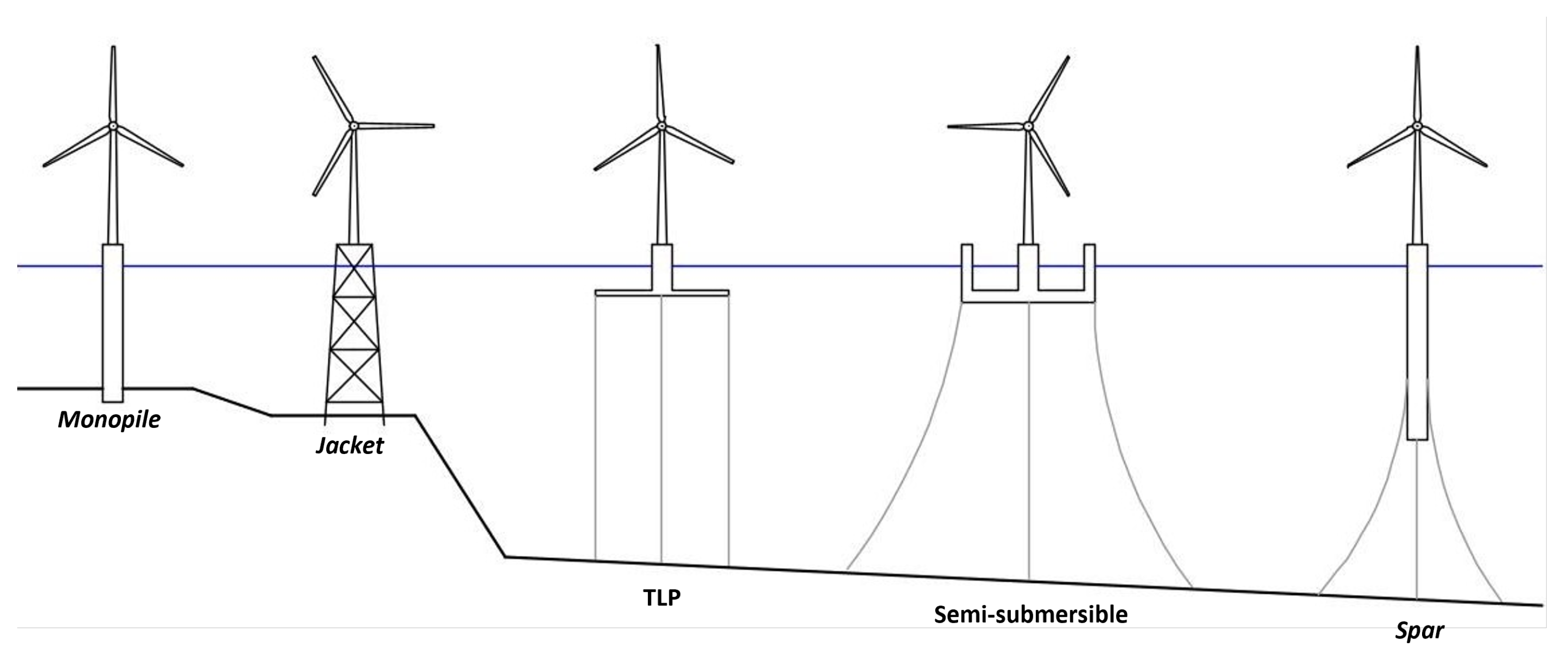
There are two main categories of Offshore Wind Turbines (OWTs), which are differentiated by their support system (see Figure 1). Fixed turbines are mounted on foundation elements that are installed onto the seabed. The most common foundation, called monopile foundations, is utilized for water depths of 0 to 30 m. For deeper regions, there are more economic fixed options—such as tripod and jacket foundations—but none are usually viable for depths over 50 m. For these scenarios, Floating Wind Turbines (FOWTs) are better suited [4].
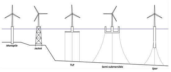
Figure 1.
Types of offshore wind turbines.
There are three main types of floating systems (see Figure 1): semi-submersible, tension leg platform (TLP), and spar. The first one, which is object of the present study, is kept in place by the restoring effects of buoyancy and a mooring system composed of catenary cables linked to the seabed. TLP turbines, which are also buoyancy-stabilized are moored by vertical tendons. Both of them can operate in depths of 50 to 120 m, but for deeper regions, ballast-stabilized spars can be more suitable [4].
Wind turbines are susceptible to periodic loads, which can induce fatigue stresses that are more intense when resonance occurs. This dynamic amplification phenomenon must be avoided in the design phase by guaranteeing that the natural frequencies do not match the known load frequency spectra. Concerning offshore wind turbines, these loads are mainly due to wind, waves, and due to alternating loads stemming from the rotation of the rotor. That means that turbine design must avoid not only the low frequencies of wind and waves [2], but also the frequencies in which the rotor operates (1P) and the blades move (3P).
In this context, an offshore wind turbine can be categorized according to its lowest tower natural frequency: if it is lower than 1P, it is called soft–soft; if it lays between 1P and 3P, it is called soft–stiff; and if it is greater than 3P, it is called stiff-stiff. Typically, it is ideal to design a soft-stiff turbine. A soft–soft turbine is considered too flexible and can be susceptible to resonance by wave loads, and a stiff-stiff one is considered too rigid, which means it is too heavy and expensive [4,5].
The modal analysis of fixed wind turbines is considered to be a well established topic; see, for instance, [4,5,6,7,8,9]. However, by what the authors of the present study could gather, the same cannot be said about floating wind turbines, especially in the case of semi-submersible platforms. There are a few studies in which floating turbine natural frequencies and modes of vibration are presented, but only as support for other analyses. In general, the sensitivity of the results to the many assumptions and approximations that must be made when modeling the structural dynamics of the FOWT is not addressed.
Ref. [10], for instance, studied a 5 MW spar turbine susceptible to an extreme dynamic structural response. The elastic modes of the tower, the spar, and the coupled system were analyzed with a 3D shell multi-body model in ABAQUS ®. It was found that the spar had a significantly higher first natural frequency than the tower. The two first modes of vibration of the coupled floating system were shown to be tower side–side and fore–aft bending modes, with frequencies slightly higher than that of the tower alone. This vibration mode showed bending behavior for both the hull and tower.
Ref. [11] developed a multi-body model to study the dynamics of a 5 MW spar turbine. The coupled rigid (rotor, nacelle, and floating platform) and flexible (tower) response was analyzed by numerically integrating the equations of motion. The system natural frequencies were calculated and the results showed that the first two flexible modes of vibration were tower bending modes. The natural frequency of a tower twisting mode was also obtained, which was significantly higher than the other ones.
Ref. [12] developed a 12 MW cross-shaped semi-submersible FOWT. By employing a beam model in the software Bladed ® (Version 4.9), the first two modes of vibration were obtained, and their respective natural frequencies were compared to the ones from a shell model developed in an in-house FE software. The first mode was shown to be a side–side tower bending mode coupled with platform rotation in the same plane. The second was a fore–aft tower bending mode coupled, again, with platform rotation in the same plane.
From the previously mentioned works, it is clear that tower stiffness is an important factor in the determination of the system’s natural frequencies, since their modes of vibration involve tower bending. They seem to also be affected by the floating platform, but this is not discussed in detail.
Ref. [13], however, studied the difference in tower design between fixed and floating foundation wind turbines. Utilizing 2D finite element models, a fixed foundation was compared to four different types of floating rigid platforms: one spar, two semi-submersibles, and one TLP. It was concluded that the first tower bending frequency increased significantly from a clamped tower to catenary moored floating platforms. By disregarding the stiffness effect of the catenary mooring system, it was also concluded that the difference in the first natural frequency was due to the large inertia of the floaters, which turned the boundary condition at the bottom of the tower into an intermediate condition between fixed (a lower frequency) and free (a higher frequency). In the case of the TLP, the first natural frequencies changed only slightly, and it was not possible to disregard the mooring system, since the cables are pre-tensioned and the boundary condition at the bottom of the tower is more stiffness-based than inertia-based. Ref. [13] also analyzed the effect of hull flexibility in tower design. Considering aerodynamic damping in the same 2D FE model, the first and second tower bending modes and frequencies of a spar-buoy with a rigid and flexible hull were obtained. It was concluded that the importance of hull flexibility depends on the stiffness of the tower in relation to the hull: for a flexible tower, the hull can be satisfactorily considered as a rigid body; but for a stiffer tower, hull flexibility is important, and taking it into account decreases the first natural frequency significantly.
Another important study was conducted by Ref. [14], who carried out a modal analysis of a 15 MW semi-submersible platform with an FE model and the hydro-elastic software HOMER ®. Various tower configurations were studied: clamped at the bottom, connected by a transitional piece to the floating platform’s fixed central column, and connected to a free platform in air and in water. The results showed that for floating turbines—just like fixed turbines—simply considering the tower clamped at the bottom results in unsatisfactory results. The transitional piece between the tower and the floater’s central column was shown to importantly reduce the natural frequency and the free–free tower + floater model resulted in a significantly higher frequency that was decreased with the consideration of added mass, which was simply modeled as an increase in mass and rotational inertia. It was also shown that hydro-static stiffness had little influence on the tower first natural frequencies.
With the goal of contributing to the in-depth analysis of the structural modeling of FOWTs, this research presents a detailed modal analysis of a 15 MW semi-submersible FOWT, aiming at identifying not only its natural frequencies—for modal alignment verification—but also the defining factors influencing such results. To achieve that, 3D finite element beam models of the tower and the floater were built and coupled in ANSYS Mechanical ®. Rotor-Nacelle Assembly (RNA) was assumed to be a rigid body, no damping was considered, and hydro-dynamic effects were taken into account by considering the hydro-static stiffness and added mass of all components of the floating unit. Regarding the latter, two different models were tested: first, a beam model with constant added mass (evaluated for zero frequency of oscillation) was adopted; then, a lumped mass matrix was used in an iterative process to account for the variation in added mass with the oscillation frequency. Finally, the mooring lines and the hydro-static effect were implemented by means of a linearized stiffness matrix.
The novel aspect of the paper is the better understanding of the dynamic behavior of FOWTs. By means of a case study, it was possible to derive the high dynamic coupling between the tower and the floating platform and to identify the effect of the latter’s inertia on the system’s behavior. Two ways of modeling added mass are presented and their advantages and limitations are described. The paper also analyzes the accuracy of implementing added mass for zero frequency and whether it is adequate to disregard the effects of the mooring lines.
2. Methodology
2.1. Finite Element Models
FOWT models were implemented in the commercial FEM software ANSYS Mechanical 2022 R2 ® by means of its parametric programming language APDL ® 2022 R2 (Language guide at [15]). Tower and floating platform were separately modeled by flexible beam elements and coupled together afterwards, thus allowing the investigation of the dynamic behavior not only of the whole system, but also of each isolated component. The RNA was considered to be a rigid body and was implemented as a nodal inertial element at the top of the tower. The floating platform’s ballast was also implemented with nodal inertial elements, but it was distributed along the corresponding nodes of the FE mesh. The same was done to model the added mass, which was interpreted at first as a literal increase in the mass of the submerged floater components.
2.1.1. Tower and RNA
The tower and RNA were chosen to be the ones from the floating version of the 15 MW IEA reference wind turbine, whose properties are available at [16]. The 135 m tower has a varying annular cross section, whose thickness and external diameter are functions of the height. Each of its segments—in which the thickness is constant and the outer diameter varies linearly—was implemented using a BEAM188 tapered element.
For the RNA implementation, a local coordinate system centered at the top of the tower and parallel to the global system shown in Figure 2 was utilized. The nacelle plus the hub mass and rotational inertia around the described system axes were obtained directly from [16]. The rotor mass and rotational inertia were approximately calculated from the blade properties—also indicated in [16]—assuming them to be rigid prismatic beams of mass 65,250 kg and length 120 m in a vertical plane normal to wind. The combined inertia of the rotor, hub, and nacelle were obtained (Table 1) and used as the input for a MASS21 element applied to the top node of the tower.
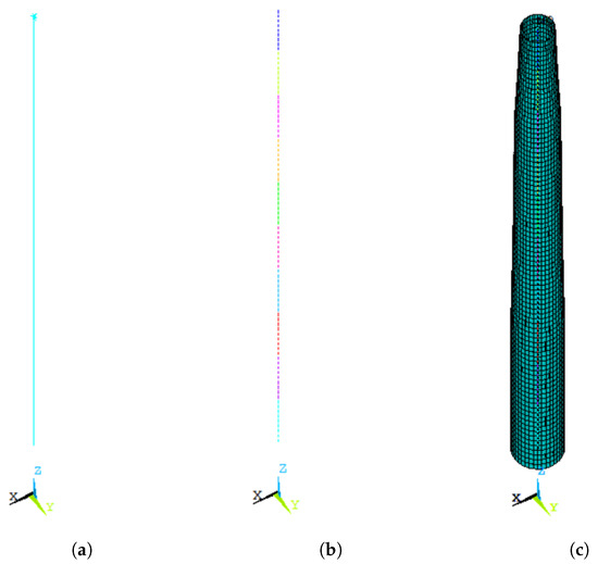
Figure 2.
Tower model: (a) beam model; (b) FE mesh—each color represents one beam element; (c) rendered view of beam elements.

Table 1.
RNA inertia.
Figure 2 shows the tower + RNA model in the ANSYS Mechanical ® graphic interface, utilizing its native representation: the beam model with the MASS21 element at the top node (Figure 2a), the FE mesh (Figure 2b), and the rendered cross sections of the beam elements (Figure 2c). Different levels of refinement of the finite element mesh of the tower model—and of all other models shown here—were tested and convergence was achieved. The meshes shown here were considered adequate.
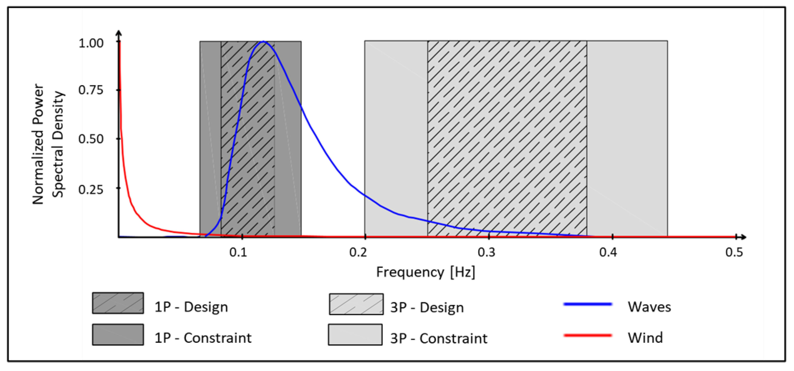
The frequency range of the rotor dynamic loads (1P and 3P) are represented in Figure 3, alongside those from wave and wind (adapted from [17]). The rotor speed was designed to vary within the 1P-Design range, but, due to the fact that the turbine floats, it can achieve frequencies outside of this spectrum, which are represented by 1P-Constraint. 3P-Design and 3P-Constraint are the respective passing blade frequency ranges [17]. For this particular case, a soft–stiff turbine would not be optimal, because a fundamental frequency between 1P and 3P would coincide with wave frequencies. In this case, a stiff–stiff turbine is better suited.

Figure 3.
Load frequency spectra. Adapted from [17].
2.1.2. Floating Platform
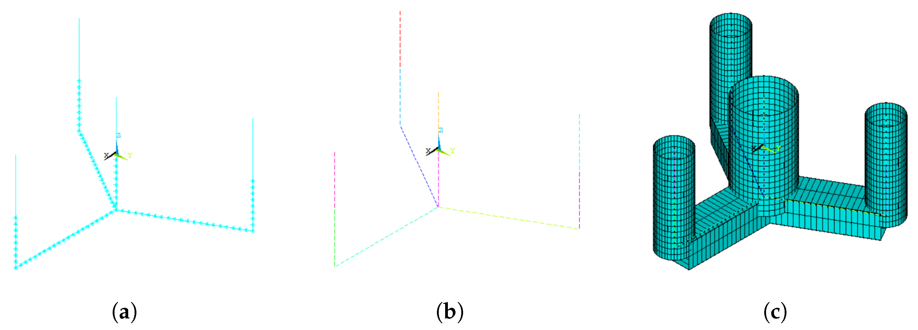
The floater is composed of four cylindrical columns with an annular cross section and the same length and draft. The central column supports the tower and is connected to the three orbital columns by pontoons composed of a rectangular hollow cross section. The dimensions of such components were taken from [18] and are shown in Table 2. All these elements were implemented by BEAM188 elements.
Table 2.
Floater dimensions.
The ballast is composed of water and occupies the whole internal volume of the pontoons and a fraction of the internal volume of the columns (14.6 m from their base). Its mass was distributed along the beams by applying MASS21 elements to the corresponding nodes of the FE mesh. Their inputs were the result of dividing the total ballast’s mass by the number of corresponding nodes.
The added mass of each element (pontoons and semi-submersible columns) was approximately calculated using strip theory (i.e., the added mass part of Morison’s equation), disregarding added mass in the element’s axial directions. This method relies on the use of empirical added mass coefficients for the columns and pontoons that need to be estimated somehow. In this work, the following approximate approach was employed:
- The added mass of the columns in the global system (parallel to their local systems) was assumed to be , corresponding to the theoretical value for a circle (2D problem) in infinite fluid and a small amplitude of oscillation;
- The software WAMIT ® (version 7.0.6) [19] was used to calculate the added mass of the whole floater in the x, y, and z global directions for an infinite period of oscillation. The global coordinate system is that shown in Figure 4;
 Figure 4. Floater model: (a) beam model; (b) FE mesh — each color represents one beam element; (c) rendered view of beam elements.
 - The added mass of the three pontoons in the horizontal direction was estimated by subtracting the contribution of the columns from the surge added mass computed with WAMIT ®. From that, it was possible to approximate the added mass of each pontoon in their respective local coordinate systems—the x axis parallel to the respective beam axis—by assuming that the added mass coefficient was constant across the whole length of the pontoons. This resulted in ;
- The same was done for the vertical direction, but using the heave added mass, resulting in .
This approach is far from ideal. Since the wetted length of the columns correspond to cylinders with a small aspect ratio (approximately 1.5 for the orbital columns and 0.88 for the central columns), the added mass coefficients from the 2D flow are questionable. In addition, the infinite fluid hypothesis is also invalid due to the presence of the free surface and the typical oscillation frequencies. However, even with those limitations, the adopted approach is considered a good first approximation to evaluate the effects of the added mass on the natural frequencies and modes of vibration. A second approach is discussed later in this text, after some key conclusions are drawn from the first one.
Because the added mass was interpreted as a literal increase in mass, it was implemented in ANSYS ® in the same way as the ballast—with the caveat of rotating the coordinate systems of the nodes of the pontoons and having different inputs of inertia in different directions (which is possible with MASS21).
Figure 4 shows the models constructed using ANSYS ®.
2.1.3. Coupled Model
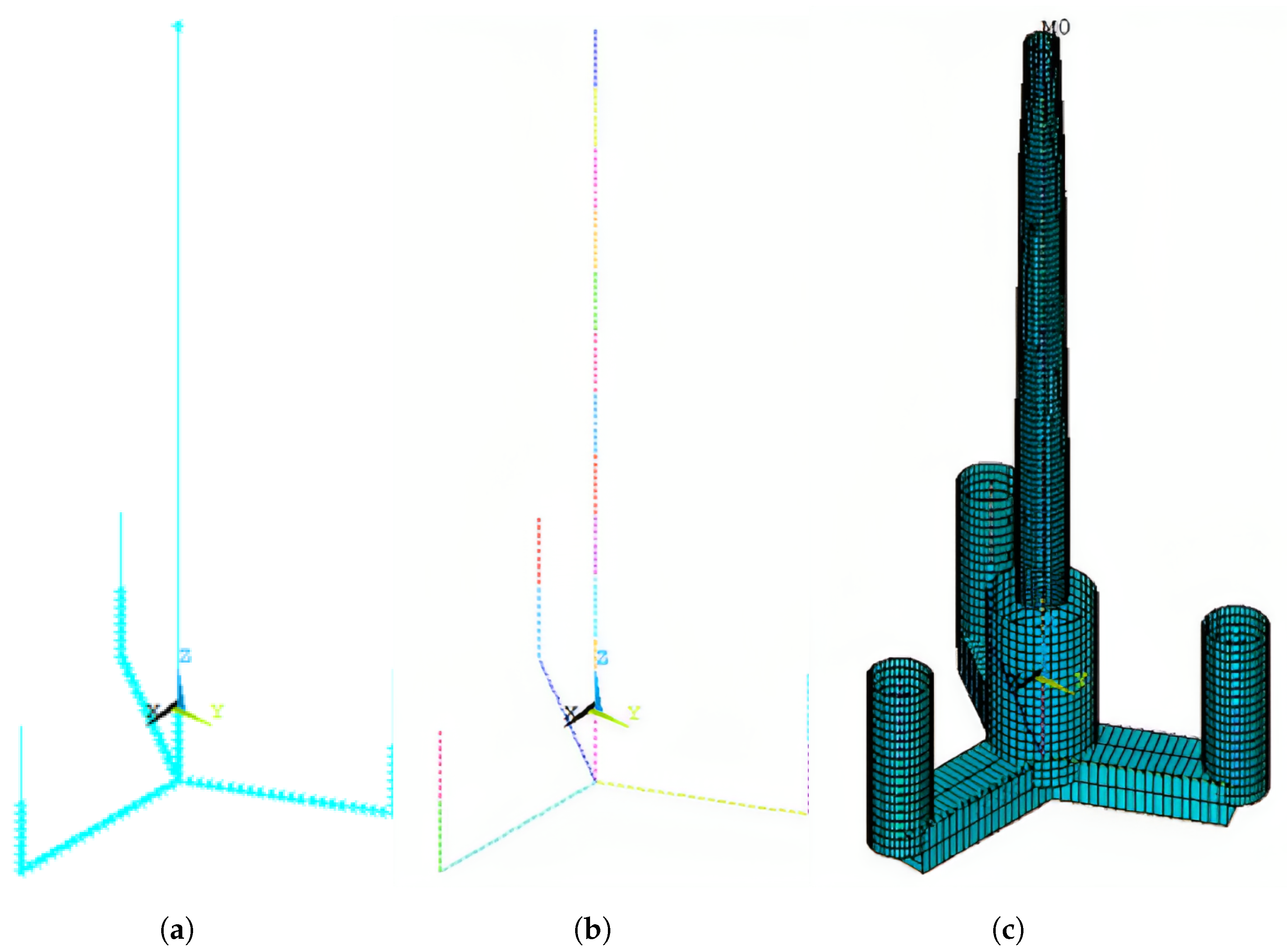
By rigidly connecting the top of the central column to the base of the tower, the coupled model was obtained. The result is shown in Figure 5.
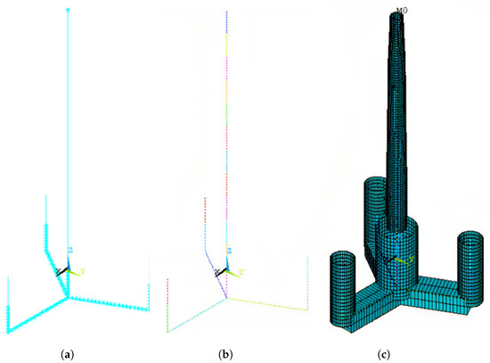
Figure 5.
Turbine model: (a) beam model; (b) FE mesh — each color represents one beam element; (c) rendered view of beam elements.
3. Results
The natural frequencies and modes of vibration of the isolated tower, the isolated floater, and the coupled turbine were obtained by running the modal analysis of the respective models. The results are presented in the following sections. For the sake of conciseness, only the first modes of vibration are shown. Some of the higher modes are illustrated in Appendix A.
3.1. Isolated Tower and Floating Platform
The tower modal analysis was run with three different boundary conditions at the bottom: free, pined, and fixed. The respective models were called free–free, pined–free, and clamped–free tower. The first six natural frequencies corresponding to flexible body vibration modes are represented in Table 3.
Table 3.
Tower natural frequencies.
As expected, restricting the bottom of the tower led to lower natural frequencies. For all scenarios, the first vibration mode was side–side bending, and the second, fore–aft bending. The first ones are illustrated in Figure 6. The first two clamped–free natural frequencies are comparable to those obtained by Ref. [14] for the same tower model with shell elements and a flexible RNA, which shows that not much is lost by the simplifications adopted here (the beam model and rigid RNA).
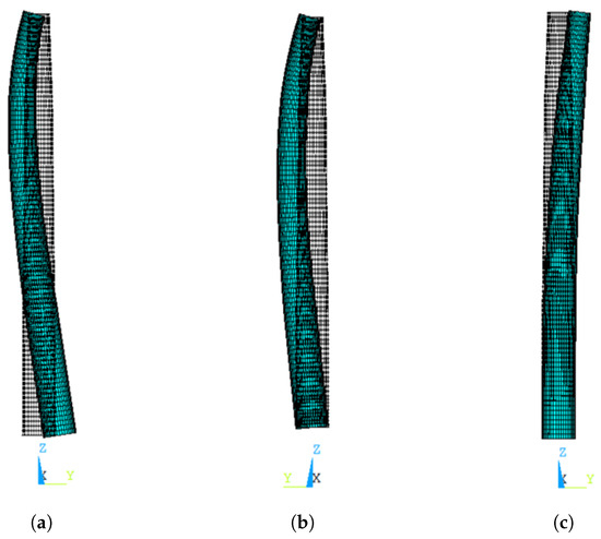
Figure 6.
Tower fundamental mode—side–side bending: (a) free bottom; (b) pined bottom; (c) clamped bottom.
The first six natural frequencies of the floater are presented in Table 4. The first modes involve pontoon deformation with corresponding rigid-body movement of the columns. Some of them are shown in Figure 7. No boundary condition was implemented and, therefore, the six first frequencies calculated by modal analysis are zero and correspond to rigid-body motions. That is why the first frequency listed in Table 4 is labeled as the 7th. As can be seen, the natural frequencies of the floater are significantly higher than those of the tower (any type of boundary condition).
Table 4.
Floater natural frequencies.
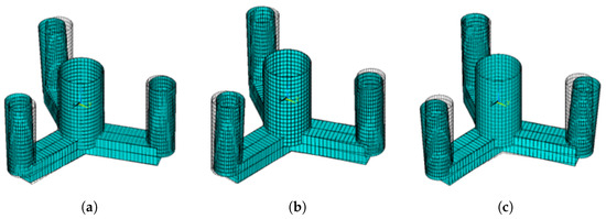
Figure 7.
First vibration modes of the floating platform: (a) 7th mode; (b) 8th mode; (c) 9th mode.
3.2. Coupled Model
The FOWTs first six natural frequencies are listed in Table 5. No boundary condition other than the rigid connection between floater and tower was implemented. The methodology and results of implementing movement restriction from the mooring are presented in Section 3.2.3.
Table 5.
Turbine natural frequencies.
By analyzing these results and using Figure 3 as a reference, it is clear that, in the context of this case study, the first two natural frequencies coincide with the 3P-Constraint spectrum, which means that the turbine would experience events of resonance during its lifespan in the occasions that the rotor achieves speeds outside of the expected design spectrum. It is also clear that the natural frequencies of the turbine are not too similar to either the isolated tower or the isolated floater, which means that there is significant dynamic coupling between the two of them.
The two first modes are shown in Figure 8 and Figure 9. They are tower bending modes—side–side and fore–aft, respectively—followed by practically rigid rotation of the floating platform—except for a slight bending of the central column, accompanying the tower. This means that, in terms of stiffness, the tower controls the dynamic behavior of the structure. Stiffening the floater would probably have a small effect on increasing the first natural frequencies of the turbine, since it is already rigid.
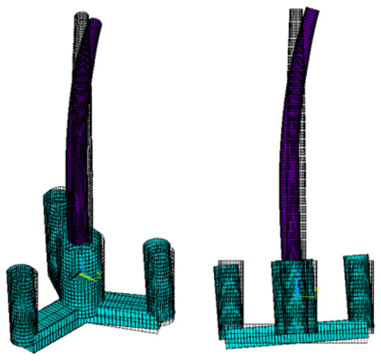
Figure 8.
Turbine Side–side bending.
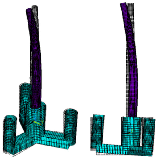
Figure 9.
Turbine Fore–aft bending.
Because natural frequencies and vibration modes are also affected by inertia, and not only by stiffness, some tests involving the mass elements of the floater were performed, as discussed in the following.
3.2.1. Influence of Floater Inertia
Due to the approximate approach adopted to include the added mass of the floater, it is important to verify the relevance of the added mass for the first frequencies and modes of vibration of the turbine. As a first test, the added mass was simply disregarded, which resulted in a slight increase in the fundamental frequency to 0.475 Hz—enough to bump it outside of the 3P-Constraint range. That indicates that added mass cannot be disregarded when analyzing the dynamic behavior of a semi-submersible FOWT, and that it requires more a robust model, which is presented in Section 3.2.2.
As a complementary test, the ballast mass was also disregarded. The fundamental frequency increased even more, to 0.563 Hz. It is possible to conclude from these results that the floating platform affects the coupled system mainly by its inertia, and not by its stiffness. Also, these frequencies, which correspond to tower bending modes, stand between the fundamental frequencies of the free–free tower and the clamped–free tower. The more inertia the floating platform has, the more the turbine’s fundamental frequency approaches that of the clamped–free tower. Furthermore, as is concluded in Section 3.2.3, implementing mooring–based boundary conditions led to negligible changes in the system’s natural frequencies. This conclusion is aligned with that obtained by Ref. [13]: the boundary conditions of catenary moored turbines are not stiffness–based, but inertia–based and controlled by the floater.
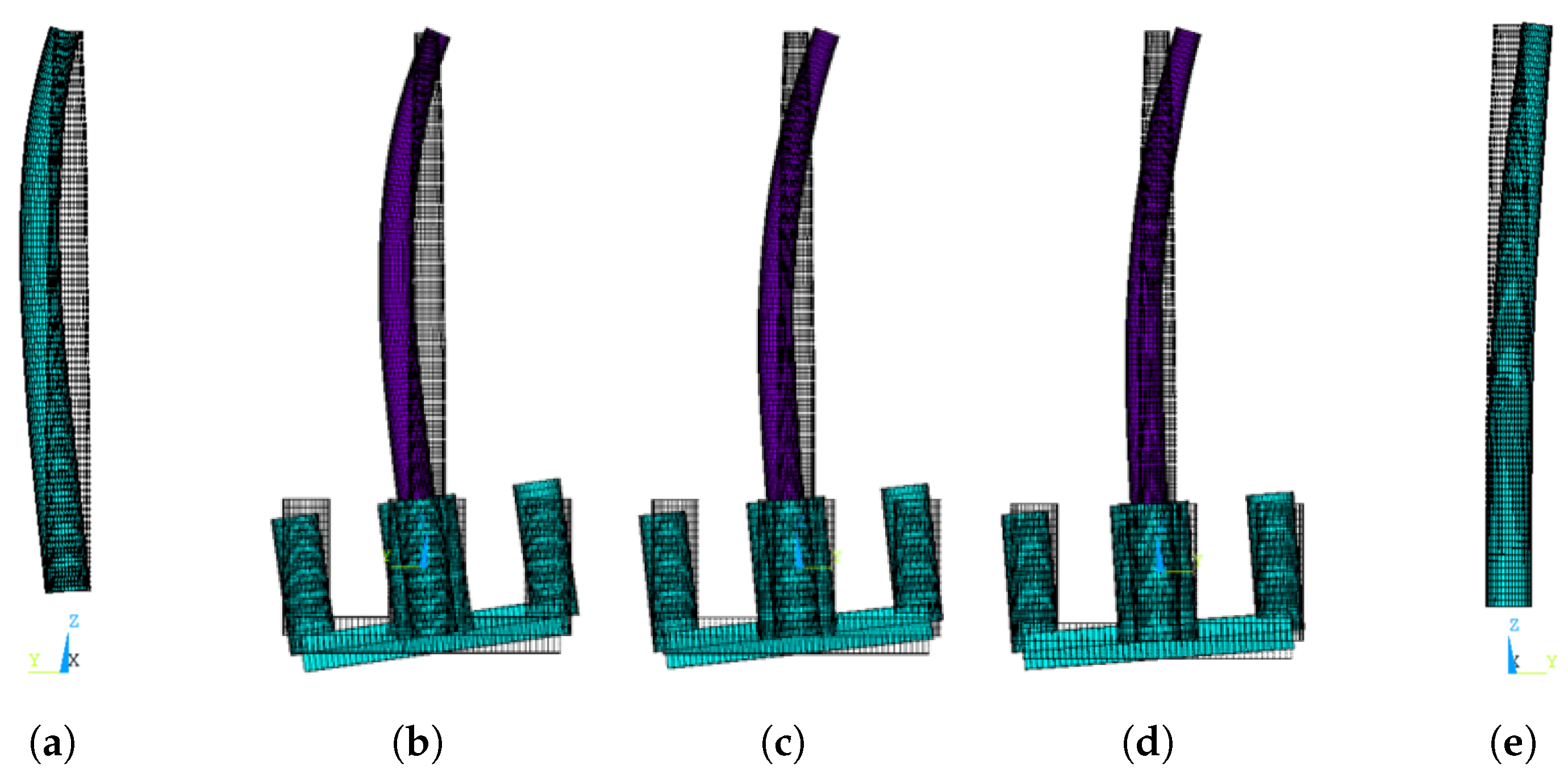
However, by analyzing the corresponding modes of vibration—as shown in Figure 10—it is possible to see that, by taking inertia out of the floating platform, the turbine mode actually approaches the pined–free isolated tower mode. The relative rotation of the floater increases but there is no transversal displacement, as opposed to the free–free condition. This means that a semi-submersible FOWT has a fundamental frequency and mode of vibration that involves the bending of its tower in a intermediary position between a pined–free isolated tower and a clamped–free isolated tower, and that the relative position is defined by the rigid floater’s rotational inertia in the bending plane. In other words, the floater works as a sort of boundary condition to the tower, which totally prevents displacement and partially restricts rotation according to how much rotational inertia it presents.
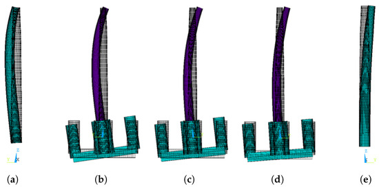
Figure 10.
Influence of floater inertia: (a) pined–free tower (0.682 Hz); (b) coupled system with no added mass or ballast (0.563 Hz); (c) coupled system with ballast but no added mass (0.441 Hz); (d) coupled system with both ballast and added mass (0.429 Hz); and (e) clamped–free tower (0.290 Hz).
The turbine’s intermediate position can be used as a loose prediction of the turbine’s fundamental frequency: a designer can estimate a range of possible turbine frequencies by calculating the fundamental frequencies of the isolated tower with pined and clamped base. Furthermore, it would be possible to manipulate the platform’s geometry to change its rotational inertia and consequently change the fundamental frequency as needed. That, together with adjustments in the tower stiffness, can be helpful in the structural design.
3.2.2. Frequency-Dependent Added Mass Modeling
Because the first two natural frequencies of the turbine are critical in terms of resonance, and given that they practically only involve rigid motions of the floater, a reasonable approach is to effectively model the floater as a rigid body. To do so, a new node was defined at the center of mass of the floater in the isolated tower model. It was rigidly connected to the tower’s base by a MPC184 Rigid Beam element and received a MASS21 element, whose inputs were the diagonals of the floater inertia—taken from ANSYS ®, and including ballast—plus the added mass—computed for an infinite period and obtained from WAMIT ®.
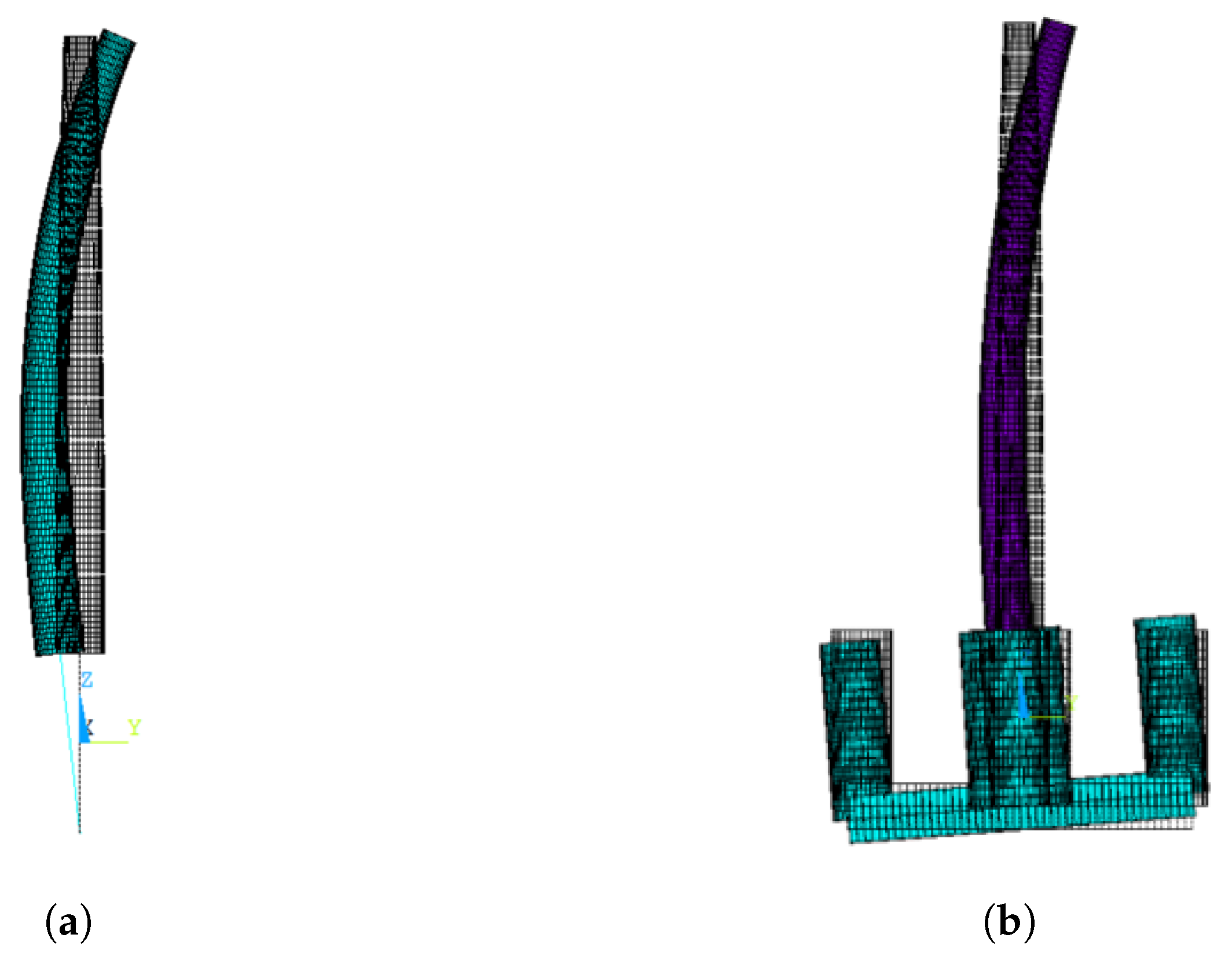
As expected, the resulting first two modes of vibration were side–side and fore–aft tower bending modes. The corresponding frequencies were higher than those obtained for the full-flexible model: 0.462 and 0.512 Hz, which are just outside the 3P-Constraint range. According to this model, resonance would not occur and the FOWT could be classified as stiff–stiff in this case study. The side–side bending mode is shown in Figure 11 next to the the full-flexible turbine model, for comparison.
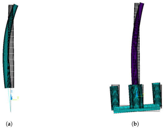
Figure 11.
Turbine’s fundamental mode of vibration for the two models: (a) rigid floater model; (b) Full–flexible model.
A major advantage of modeling the floater as a rigid body is that there is no need for approximating the added mass as was done in the previous sections, which adopted simple added mass coefficients distributed along the columns and pontoons of the platform. Since now the added mass is modeled by lumped values, it is possible to easily take into account the variations with respect to the frequency of oscillation by directly using the values computed with WAMIT ®. This does not take into account hydro-elastic effects, which would require more sophisticated methods to model the couplings between the structural and hydro-dynamic problem, but this is expected to be a problem only for higher modes.
With this second approach for including the added mass of the floater, it is possible to employ an iterative procedure to better estimate the values at the first natural frequency: the natural frequency obtained by modal analysis is used to obtain added mass values from WAMIT ® results, which are updated in ANSYS ® to compute a new natural frequency, which leads to an updated added mass and so on. As summarized in Table 6, it turns out that convergence is obtained with the same value of natural frequency as the one computed considering the added mass evaluated for zero frequency, i.e., the aforementioned 0.46 Hz. This indicates that the infinite period simplification can be used with little loss in accuracy.
Table 6.
Frequency-dependent added mass modeling and comparison with the original approach (slender body).
3.2.3. Turbine Boundary Conditions: Mooring and Hydro-Static Effect
As stated in Section 3.2, no external boundary conditions were implemented to the tower + floater coupled system. In reality, the turbine is kept in place by buoyancy and by a catenary mooring system, as described in Section 1, which can be modeled by matrices and represent the turbine’s stiffness-based boundary conditions. Ref. [13] infers that catenary stiffness should not greatly affect the structural modes because their rigid body modes have low frequencies. In order to verify that, this section presents the methodology and results of implementing the mooring and hydro-static stiffness to the turbine FE model.
The linearized analytical method developed by [20] was utilized to calculate the mooring stiffness coefficients of matrix , which is presented in Equation (1), followed by the linear hydro-static matrix , in Equation (2) (all units in SI). Since both matrices have linear coefficients, it is possible to superimpose them to obtain a general restoring effect matrix , as shown in Equation (3).
The implementation of this stiffness matrix as a boundary condition to the FE model in ANSYS Mechanical ® was achieved using the following method:
- Two nodes were created at the structure’s center of gravity;
- One of them was restricted in all six Degrees of Freedom (DOF);
- The other was rigidly connected to the structure by a MPC184—rigid beam element;
- These two nodes were connected to each other by a MATRIX27 element.
MATRIX27 elements connect two nodes and attribute relative stiffness between them by means of a (two nodes, each with six DOF) matrix , which can have the same effect as the matrix when its coefficients are arranged in the way presented in Equation (4).
As listed in Table 7, the first six structure natural frequencies are no longer zero, even though they still correspond to rigid body vibrations. Now, they involve motion oscillation around the equilibrium position of the floating unit. The following six frequencies, presented in Table 8, correspond to the vibration modes that involve tower and floater deformation. Via a comparison with Table 5, it is clear that implementing stiffness–based boundary conditions does not lead to important changes to the fundamental tower bending modes of the floating turbine. There were also no significant changes in the modal shapes. This confirms, together with the results of Section 3.2.1, that the effect of floater inertia has much greater importance as a boundary condition on the tower bending modes than the mooring stiffness.
Table 7.
Natural frequencies of rigid body motion.
Table 8.
Natural frequencies of flexible body motion.
4. Conclusions
Aiming to contribute to the literature on the determinant factors of a FOWTs natural frequencies and modes of vibration, a 15 MW semi-submersible FOWT was taken as a case study and different assumptions for building its FE model were analyzed. Regarding the first two modes of vibration—whose frequencies are the nearest to the load spectra—the modal analysis results showed that the two primary factors are tower stiffness and floater rotational inertia. The FOWT vibration is composed of tower bending and the corresponding floater rigid rotation, which allowed the floating platform to be modeled as a rigid body when the aim was to study the natural frequencies of the first flexible modes. Both the frequency and mode of vibration of the whole system approach a clamped–free isolated tower as the rotational inertia (in the bending plane) of the floating platform is increased. As the rotational inertia of the platform is reduced, the frequency and mode approach a pined–free isolated tower.
Due to the importance of floater inertia to tower vibration, it is paramount to consider the added mass of the hull, since it contributes significantly to the total inertia. This paper investigated two ways of modeling added mass: first, the columns and pontoons were modeled using strip theory (the inertial part of Morison’s equation) with constant added mass coefficients estimated using the results from WAMIT ® (considering an infinite period of oscillation); second, the floater was considered to be a rigid body whose inertia was implemented as a nodal inertia element connected to the tower. This allowed the added mass to be directly taken from WAMIT ®, with no further simplifications, which made an iterative analysis of the vibration frequency possible. At least for the FOWT analyzed in this work, evaluating the added mass matrix for an infinite period of oscillation was enough. Furthermore, by implementing a classical linear model for the stiffness of the mooring lines, it was shown that it is possible to disregard their stiffness. The models presented in this study are based on a series of premises, which, while allowing a simplified first approach to the problem, result in some limitations that should be more thoroughly analyzed in subsequent research. The most important ones are the disregard of dampening effects, the consideration of the RNA as a rigid body, and the adaptations of added mass to a beam finite element model (interpreting it as a literal increase in mass, discretizing it in nodes in a mesh, utilizing strip theory to approximate its values, etc.). It is also important to emphasize the need for experimental validation of the presented models.
A natural continuation of this study would be to build an analytical solution based on the determinant factors here presented. That would allow designers to quickly calculate an approximate value of their tower’s natural frequency, which is useful in the early stages of a project. It would also be interesting to address the problem with more complex models: modeling the RNA as a flexible body, using a shell model instead of a beam one, or refining the analysis of the complex fluid structure interaction, e.g., dampening and hydro-elastic effects, are some of the most obvious improvements whose practical effects should be investigated.
Author Contributions
Conceptualization: A.H., A.G.N. and A.N.S.; funding acquisition: A.N.S.; methodology: A.H., L.H.S.C., A.G.N., A.N.S. and G.R.F.; project administration: A.N.S.; software: A.H., L.H.S.C., A.G.N. and G.H.R.V.; supervision: A.G.N., A.N.S. and G.R.F.; writing—original draft: A.H.; writing—review and editing: L.H.S.C., A.G.N., A.N.S., G.R.F. and G.H.R.V. All authors have read and agreed to the published version of the manuscript.
Funding
This research was funded by CNPq (Conselho Nacional de Desenvolvimento Científico e Tecnológico) grant numbers 304321/2021-4, 306342/2020-0 and 305945/2020-3.
Acknowledgments
This work was developed as part of the R&D project conducted by Petrobras and the University of São Paulo entitled “Research and Development on Deep Water Floating Offshore Wind Turbines” (agreement Petrobras #5900.0112605.19.9). The authors wish to thank Petrobras for the funding of this project and the Brazilian National Petroleum Agency (Agência Nacional do Petróleo, ANP) for providing the regulatory framework under which this funding takes place.
Conflicts of Interest
The authors declare no conflict of interest. The funders had no role in the design of the study; in the collection, analyses, or interpretation of data; in the writing of the manuscript; or in the decision to publish the results.
Appendix A. Higher Modes of Vibration
For the sake of completeness, this section contains the rendered views of the first six modes of vibrations of the main models presented in the study. Figure A1–Figure A6 illustrate the vibrations modes of the free–free, pined–free, and clamped–free tower, the floating platform, the coupled turbine, and the turbine modeled with a rigid floater, respectively, indicating their frequencies. In the modes of vibration that involve torsion (Figure A1, Figure A2, Figure A3, Figure A5 and Figure A6), the axial rotation is represented in ANSYS ® by an increase in diameter—the larger the torsional rotation, the larger the increase in diameter.
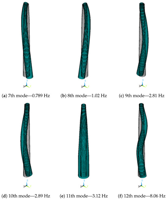
Figure A1.
Free–free tower vibration modes.
Figure A1.
Free–free tower vibration modes.
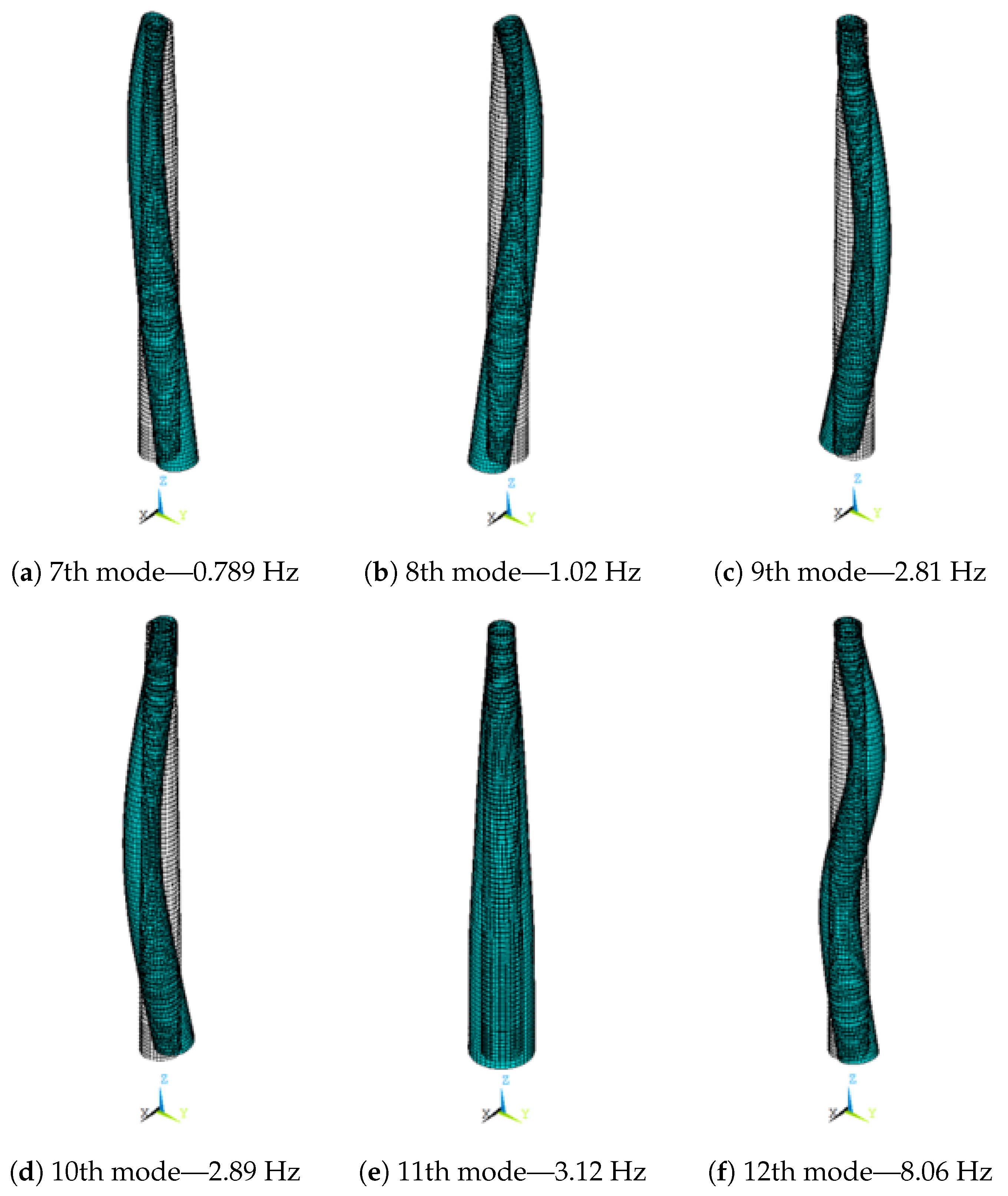
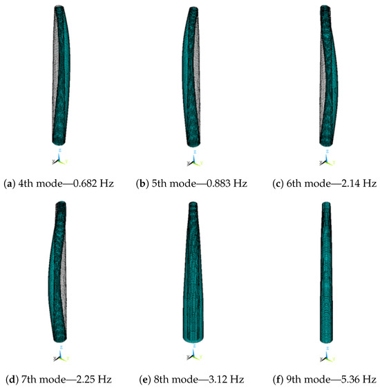
Figure A2.
Pined–free tower vibration modes.
Figure A2.
Pined–free tower vibration modes.
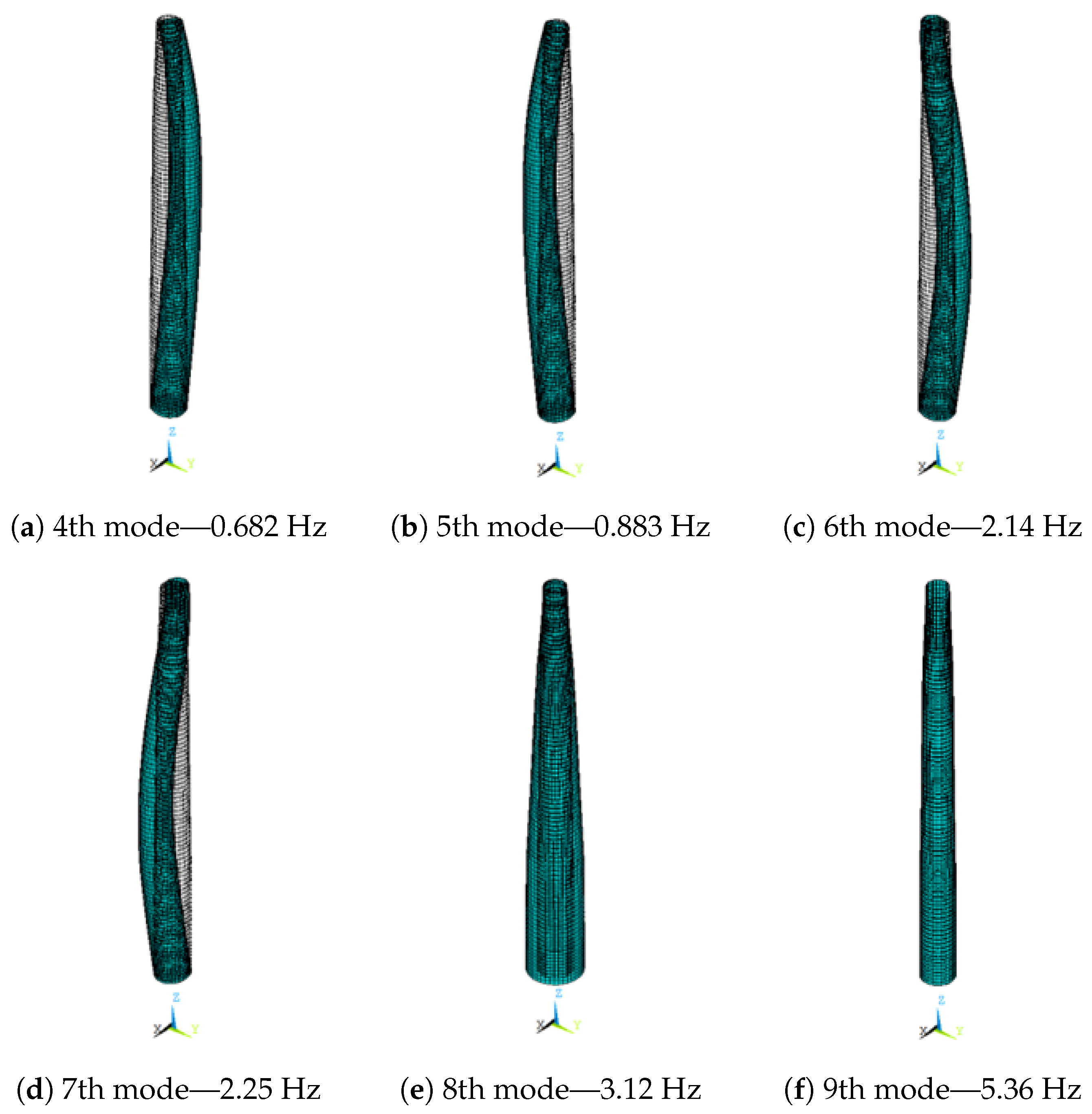
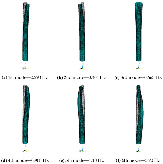
Figure A3.
Clamped–free tower vibration modes.
Figure A3.
Clamped–free tower vibration modes.
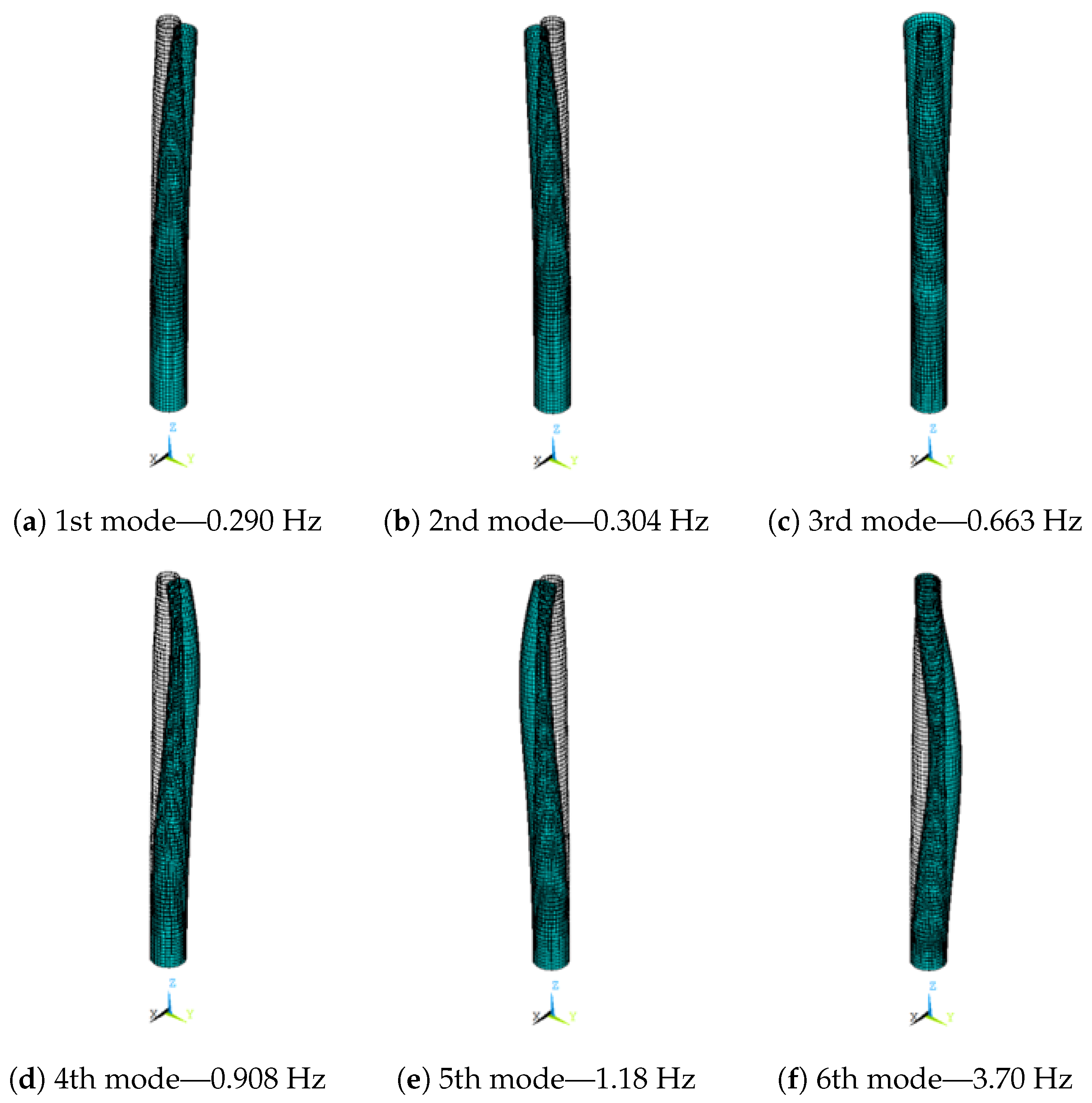
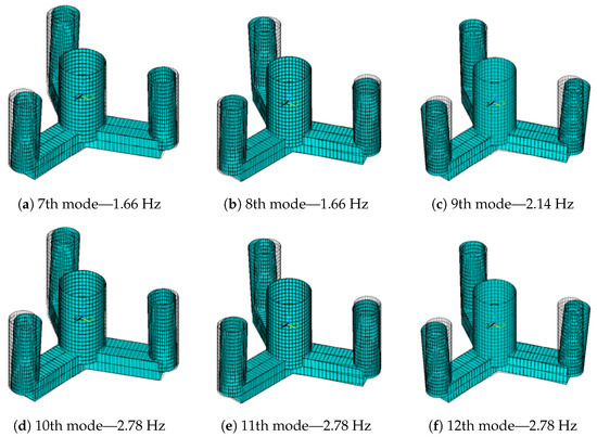
Figure A4.
Floating platform vibration modes.
Figure A4.
Floating platform vibration modes.
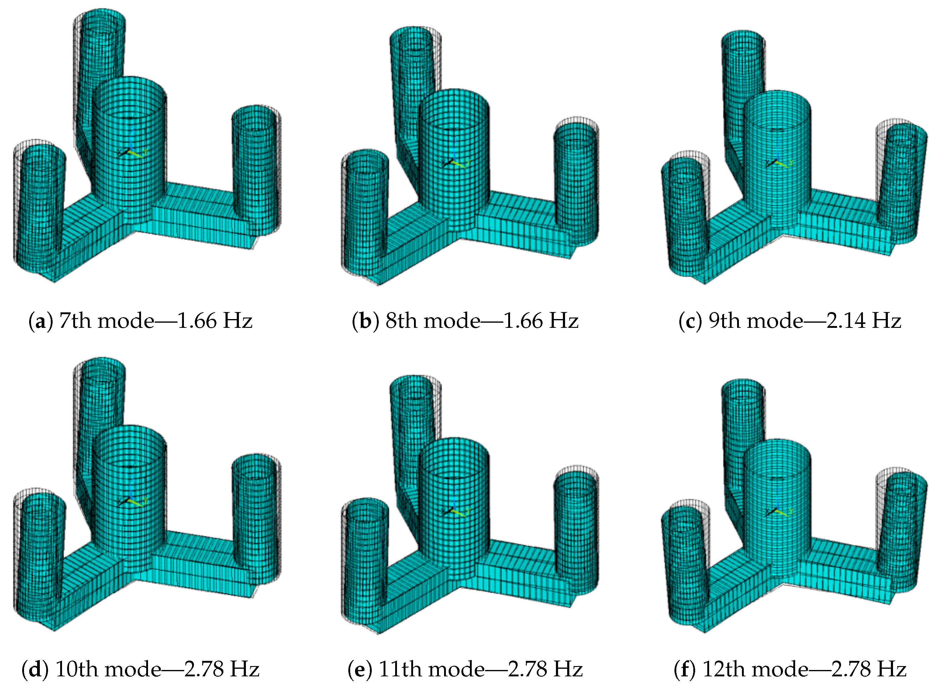
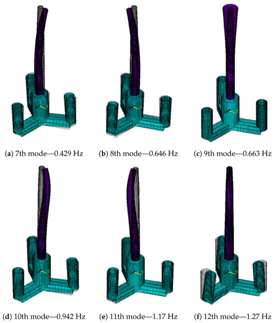
Figure A5.
Turbine vibration modes.
Figure A5.
Turbine vibration modes.
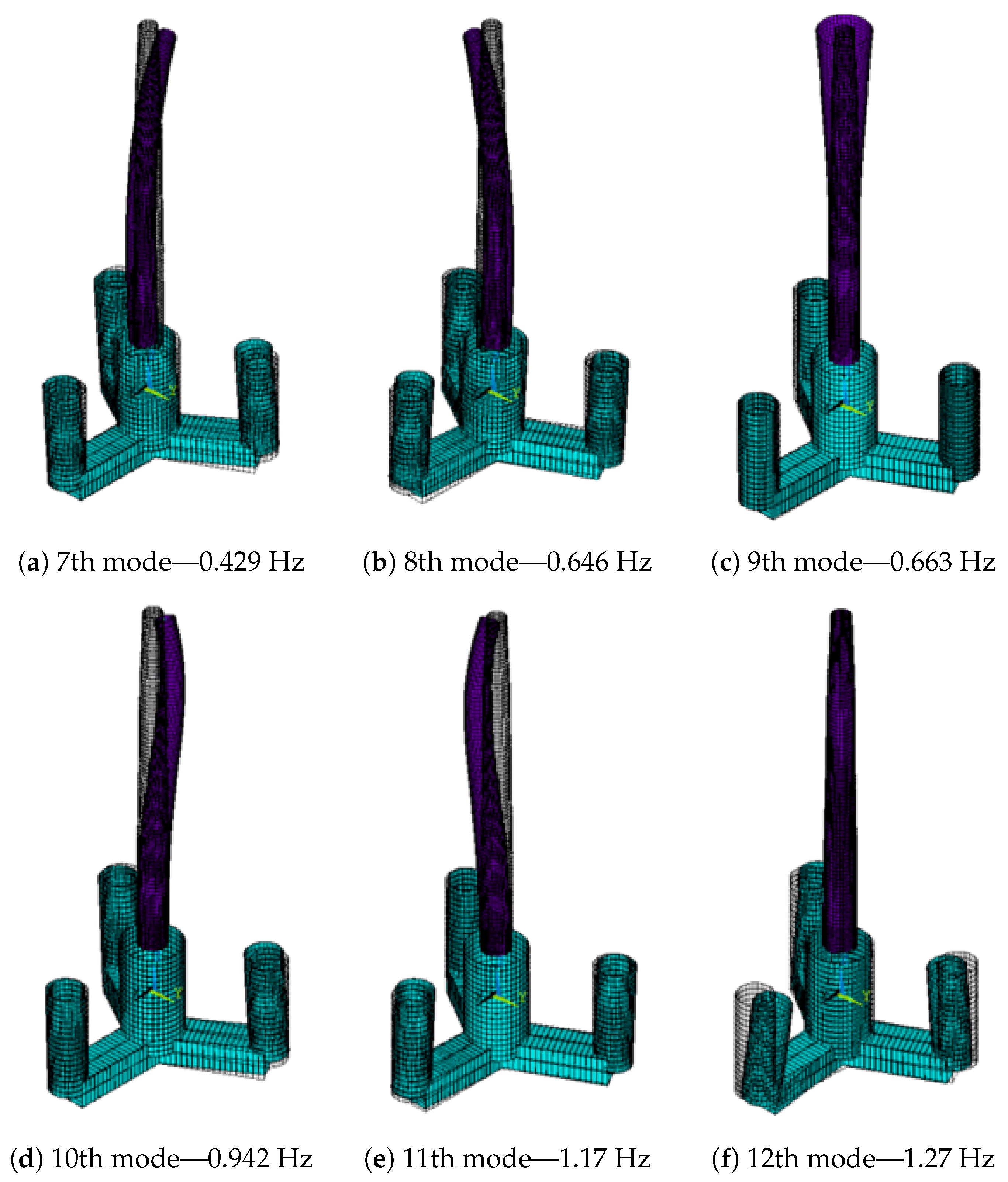
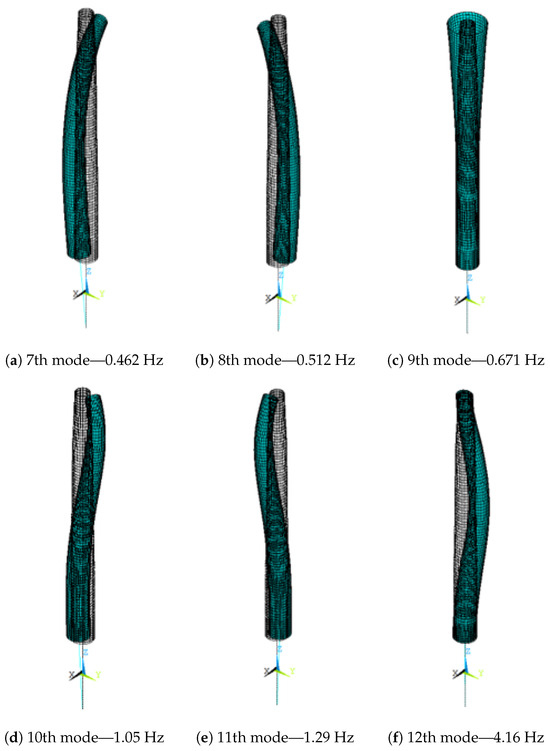
Figure A6.
Vibration modes of tower with rigid floater.
Figure A6.
Vibration modes of tower with rigid floater.

References
- WWEA. World Market for Wind Power Saw Another Record Year in 2021: 97,3 Gigawatt of New Capacity Added. 2022. Available online: https://wwindea.org/world-market-for-wind-power-saw-another-record-year-in-2021-973-gigawatt-of-new-capacity-added/ (accessed on 18 August 2022).
- Arshad, M.; O’Kelly, B.C. Offshore wind-turbine structures: A review. Proc. Inst. Civ. Eng. Energy 2013, 166, 139–152. [Google Scholar] [CrossRef]
- IEA. Offshore Wind Outlook 2019: World Energy Outlook Special Report. Paris. Available online: https://www.iea.org/reports/offshore-wind-outlook-2019 (accessed on 18 August 2022).
- Jahani, K.; Langlois, R.G.; Afagh, F.F. Structural dynamics of offshore Wind Turbines: A review. Ocean. Eng. 2022, 251, 111136. [Google Scholar] [CrossRef]
- Arany, L.; Bhattacharya, S.; Macdonald, J.H.; Hogan, S.J. Closed form solution of Eigen frequency of monopile supported offshore wind turbines in deeper waters incorporating stiffness of substructure and SSI. Soil Dyn. Earthq. Eng. 2016, 83, 18–32. [Google Scholar] [CrossRef]
- Jalbi, S.; Shadlou, M.; Bhattacharya, S. Practical Method to Estimate Foundation Stiffness for Design of Offshore Wind Turbines; Elsevier Inc.: Amsterdam, The Netherlands, 2017; pp. 329–352. [Google Scholar] [CrossRef]
- Adhikari, S.; Bhattacharya, S. Dynamic analysis of wind turbine towers on flexible foundations. Shock Vib. 2012, 19, 37–56. [Google Scholar] [CrossRef]
- Abdullahi, A.; Wang, Y.; Bhattacharya, S. Comparative modal analysis of monopile and jacket supported offshore wind turbines including soil-structure interaction. Int. J. Struct. Stab. Dyn. 2020, 20, 2042016. [Google Scholar] [CrossRef]
- Ferreira, Y.A.; Vernizzi, G.J.; Futai, M.M.; Franzini, G.R. A reduced-order model to predict the natural frequencies of offshore wind turbines considering soil-structure interaction. Mar. Syst. Ocean. Technol. 2022, 17, 80–94. [Google Scholar] [CrossRef]
- Karimirad, M.; Moan, T. Extreme Dynamic Structural Response Analysis of Catenary Moored Spar Wind Turbine in Harsh Environmental Conditions. J. Offshore Mech. Arct. Eng. 2011, 133, 041103. [Google Scholar] [CrossRef]
- Al-Solihat, M.K.; Nahon, M. Flexible multibody dynamic modeling of a floating wind turbine. Int. J. Mech. Sci. 2018, 142–143, 518–529. [Google Scholar] [CrossRef]
- Matsuoka, R.; Takeda, T.; Kusumoto, H.; Kuwada, S.; Yoshimoto, H.; Kamizawa, K. Development of 12MW Cross-Shaped Semi-Submersible Floating Offshore Wind Turbine. In Proceedings of the ASME 2022 41st International Conference on Ocean, Offshore and Arctic Engineering, Hamburg, Germany, 5–10 June 2022; Volume 8. Ocean Renewable Energy. [Google Scholar] [CrossRef]
- Hsu, C.G. Substructure Models for Dynamic Analysis of Floating Wind Turbines and the Effect of Hull Flexibility. Master’s Thesis, Delft University of Technology, Delft, The Netherlands, Norwegian University of Science and Technology, Trondheim, Sweden, 2019. Available online: http://resolver.tudelft.nl/uuid:5b3e0987-5ddb-4741-8442-791f8c04a297 (accessed on 18 August 2022).
- Sizova, S.; Maillot, E.; Moreau, S.; Féron, M. Influence of the Semi-Submersible Platform Flexibility on the Dynamic Response of the Wind Turbine. In Proceedings of the ASME 2022 41st International Conference on Ocean, Offshore and Arctic Engineering, Hamburg, Germany, 5–10 June 2022; Volume 8. Ocean Renewable Energy. [Google Scholar] [CrossRef]
- Strain, J.; Miller, E.; PADT Inc. Introduction to the ANSYS Parametric Design Language (APDL): A Guide to the ANSYS Parametric Design Language, 1st ed.; CreateSpace Independent Publishing Platform: North Charleston, SC, USA, 2013; Available online: https://www.amazon.com/Introduction-ANSYS-Parametric-Design-Language/dp/1537133993 (accessed on 18 August 2022).
- Gaertner, E.; Rinker, J.; Sethuraman, L.; Zahle, F.; Anderson, B.; Barter, G.E.; Abbas, N.J.; Meng, F.; Bortolotti, P.; Skrzypinski, W.; et al. IEA Wind TCP Task 37: Definition of the IEA 15-Megawatt Offshore Reference Wind Turbine; Technical Report; NREL: Denver, CO, USA, 2020. [Google Scholar] [CrossRef]
- Allen, C.; Viscelli, A.; Dagher, H.; Goupee, A.; Gaertner, E.; Abbas, N.; Hall, M.; Barter, G. Definition of the UMaine VolturnUS-S Reference Platform Developed for the IEA Wind 15-Megawatt Offshore Reference Wind Turbine; Technical Report; NREL: Denver, CO, USA, 2020. [Google Scholar] [CrossRef]
- Mas-Soler, J.; do Amaral, G.A.; da Silva, L.Z.M.; Malta, E.B.; Carmo, L.H.S.; Ruggeri, F.; Simos, A.N. A parametric optimization approach for the initial design of FOWT’s substructure and moorings in Brazilian deep-water fields. J. Phys. Conf. Ser. 2022, 2362, 012025. [Google Scholar] [CrossRef]
- Lee, C.; Newman, J. WAMIT User Manual; Versions 6.4, 6.4PC, 6.3S, 6.3S-PC; WAMIT, Inc.: Cambridge, MA, USA, 2006. [Google Scholar]
- Amaral, G.A.; Pesce, C.P.; Franzini, G.R. Mooring system stiffness: A six-degree-of-freedom closed-form analytical formulation. Mar. Struct. 2022, 84, 103189. [Google Scholar] [CrossRef]


Disclaimer/Publisher’s Note: The statements, opinions and data contained in all publications are solely those of the individual author(s) and contributor(s) and not of MDPI and/or the editor(s). MDPI and/or the editor(s) disclaim responsibility for any injury to people or property resulting from any ideas, methods, instructions or products referred to in the content. |
© 2023 by the authors. Licensee MDPI, Basel, Switzerland. This article is an open access article distributed under the terms and conditions of the Creative Commons Attribution (CC BY) license (https://creativecommons.org/licenses/by/4.0/).