Abstract
Wind systems are sustainable and economical options for producing electrical energy. These systems efficiently manage the power flow by maximizing wind power and consuming reactive power from the grid. In addition, wind systems must maintain operation despite utility grid electrical failure; hence, their control system must not collapse. This study proposes a fault-tolerant converter controller to ensure the efficient operation of wind system converters. The central concept behind this is that when there is an imbalance in the utility grid voltage due to a fault nearby or far away, positive and negative sequence voltages are created in the time domain. Then, two parallel controllers operate to allow the wind system to continue operating despite the failure. One controller utilizes positive sequence voltages as inputs to regulate the generator’s electromagnetic torque. This helps in maximizing the amount of wind energy. The second controller uses negative sequence voltages as inputs, which helps to cancel out the produced torque in the opposite direction, thereby preventing generator overload. Finally, the controllers proposed in this article are validated through simulations, and the results are presented.
1. Introduction
Power systems continuously evolve to improve their size, efficiency, technology, and variety. Renewable energies are part of this general trend, and so is the addition of new ways to regulate the grid. Power system operations are commonly centrally dispatched so that large power plants supply most of the energy consumed. Although distributed generation is increasing its input to the grid, it is not completely regulated. This condition implies larger currents in the transmission lines, bidirectional power generation, voltage control, stability, and protection coordination concerns [1]. Wind systems, as fast-growing sources of distributed generation, implicate technical challenges since they are subject to failure during operation. Moreover, power generation is not constant due to unpredictable wind energy surges and recessions, resulting in non-scheduled energy sources. These aspects have led to an interest in maximizing power while maintaining resilience to failures within the grid. Symmetrical components are usually applied to analyze either a symmetrical or asymmetrical fault, and hence, this method is employed not only to characterize the fault but also to design a torque controller able to address those difficulties.
This topic has been addressed several times with different approaches. In Ref. [2], a short-circuit study for the doubly fed induction generator is presented, defining the electromagnetic process in a coordinate space working on positive and negative sequence vector models. Nevertheless, this research is only directed to the induction generator’s excitation control. In Ref. [3], a hierarchical fault-tolerant controller is proposed, which consists of controlling the pitch angle and the maximum power point tracking during the balanced short circuit of a doubly fed induction generator-based wind energy system. This controller is developed to suppress the DC overshoots under the short-circuit conditions of the power system, but it does not consider asymmetric failures in the utility grid. In Ref. [4], the authors present a control algorithm for the rotor-side converter of a doubly fed induction generator capable of mitigating oscillations arising during line faults, endowing the system with effective low voltage ride-through capability under both balanced and unbalanced grid voltage sags without relying on dedicated auxiliary hardware, but the authors do not address the control of the grid-side converter. In Ref. [5], an improved fault-ride-through system is proposed for a wind turbine with a doubly fed induction generator that is based on the proper stator voltage control to address symmetrical as well as unsymmetrical and unbalanced grid voltage sags; additionally, a modified topology of the conventional wind system is implemented to regulate the stator voltage. They use a transformer between the rotor circuit and the electrical grid, increasing the hardware cost. In Ref. [6], a detailed analysis of the negative sequence current response under each control objective is carried out, considering all the controller parameters. Nevertheless, approximated mathematical models of the short-circuit quantities and currents are proposed. In Ref. [7], the authors propose controlling a wind conversion system’s rotor-side controller and grid-side controller based on the doubly fed induction generator under unbalanced grid voltage conditions. They focus only on the control technique of the rotor power flowing from the DC link through the grid-side converter controller in the case of line to ground faults.
The main contribution of this research is related to the design of a robust fault-tolerant control system applied to a wind system using a doubly fed induction generator. Two independent control schemes are proposed: the rotor-side and grid-side converter controllers. Both include two controllers in parallel, one in a positive sequence and the other in a negative sequence, where the symmetrical component transformation is implemented in the time domain. This research is part of an effort to explore and understand different scenarios where an asymmetric fault occurs in the electrical grid and its effect on the performance of the wind system using a doubly fed induction generator.
The content of the article is described below. Section 2 describes the wind system controller scheme. Section 3 presents the wind system model. Section 4 describes synthesizing the converter control system, which is composed of two independent controllers. Section 5 shows the symmetrical component transformation procedure in the time domain. Section 6 presents the simulation results for validating the proposed controller. Section 7 presents a discussion related to relevant aspects of the proposed fault-tolerant control system. Finally, the conclusions are shown in Section 8.
2. Wind System Controller Scheme
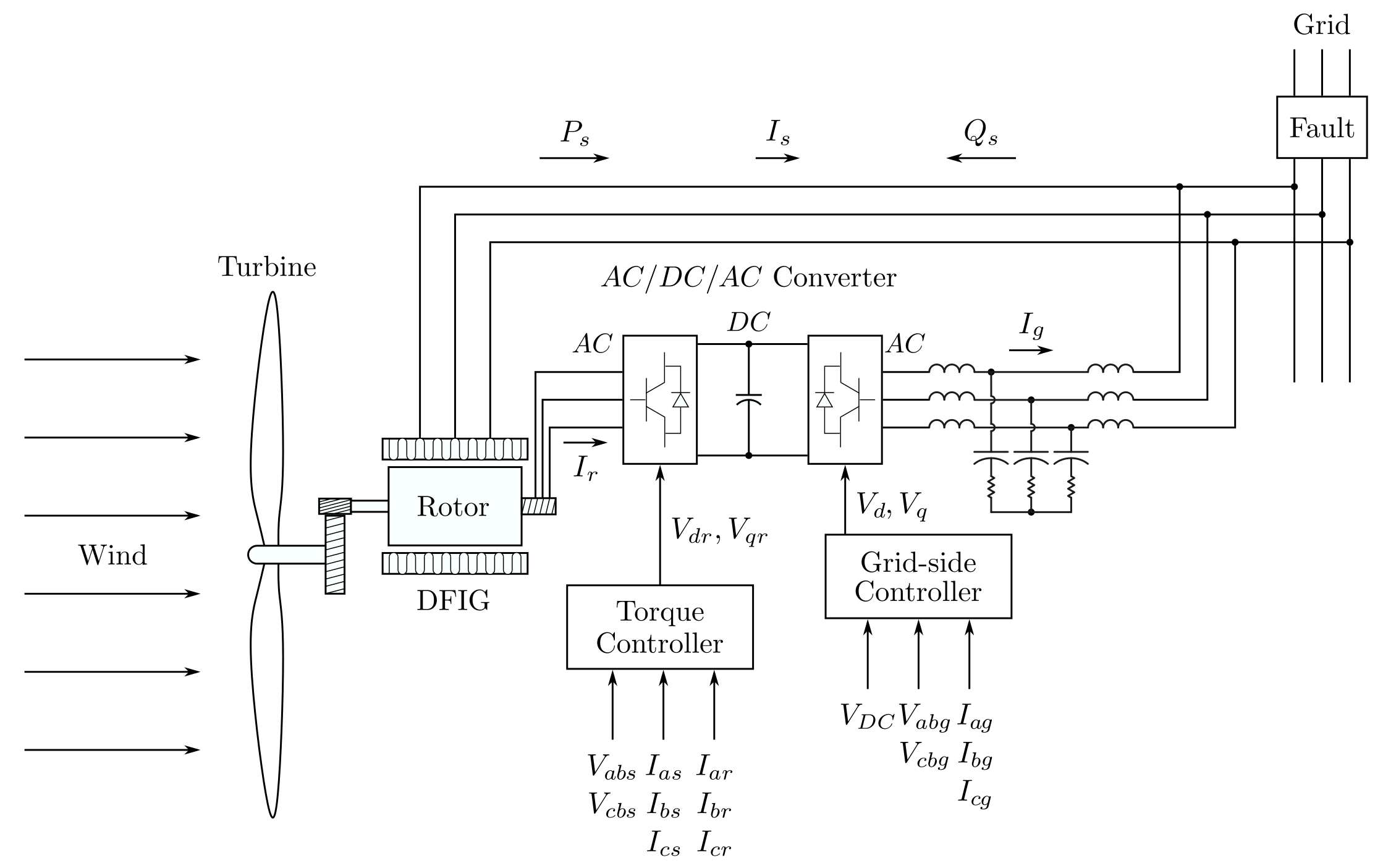
The controller design of a wind system driven by a doubly fed induction generator has two main objectives. The first is to control the electromagnetic torque of the generator, thus maximizing the capture of the wind energy. The second is to regulate the DC bus voltage of the grid-side converter, which allows for bidirectional power flow between the rotor circuit and the utility grid. The proposed scheme of the wind system controller consists of two independent controllers: the rotor-side and grid-side converter controllers [8], as shown in Figure 1.
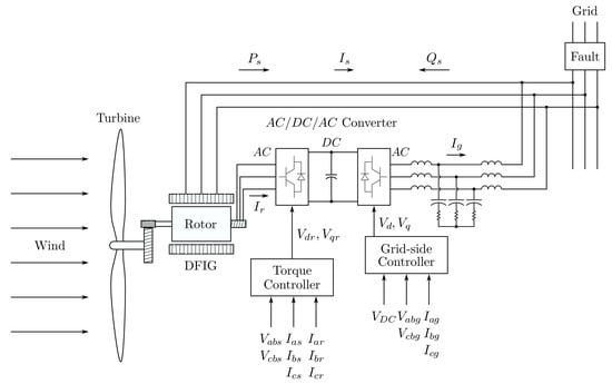
Figure 1.
Proposed scheme of the wind system controller.
It is important to consider fault-tolerant strategies that allow the wind systems to continue functioning despite the presence of an electrical failure in the utility grid. An asymmetrical fault presented in the utility grid produces unbalanced line-to-line voltages at generator terminals. Consequently, the control system is affected due to oscillations produced in the system variables referred to as the system. Therefore, this research describes a control system applied to wind systems tolerant to asymmetrical faults in the utility grid where the symmetrical component transformation is applied in the time domain. Applying the proposed methodology, it is possible to analyze an asymmetrical fault in the grid utility and its effect on the performance of the wind system driven by a doubly fed induction generator.
3. Wind System Model
The wind system is divided into three subsystems: the mechanical oscillation system, the doubly fed induction generator model, and the grid-side converter system. The mechanical system is composed of a wind turbine impelling a doubly fed induction generator. This generator is fed in both the stator and rotor winding. The stator winding directly sends a large amount of generated power to the utility grid. Meanwhile, the remaining generated power bidirectionally flows between the utility grid and the rotor circuit [9].
3.1. Oscillation Mechanical System
The mechanical oscillation equation of a wind system involves the torsional forces between the shafts of the wind turbine and the induction generator, which are coupled by a gearbox. The input torque corresponds to the turbine torque, while the generator establishes a resistive electromagnetic torque that opposes the turbine torque. The wind system’s mechanical model is as follows [10]:
where is the angular speed referred to the high-velocity generator side; is the turbine’s mechanical torque; is the electromagnetic torque developed by the generator; is the gear-teeth ratio of the gearbox, which is used to couple the low speed of the turbine with the high speed of the generator; and represent the friction coefficients of the turbine and generator, respectively, and and represent the inertia moments. Furthermore, the wind turbine’s mechanical torque involved in (1), i.e., , can be approximated as follows [11]:
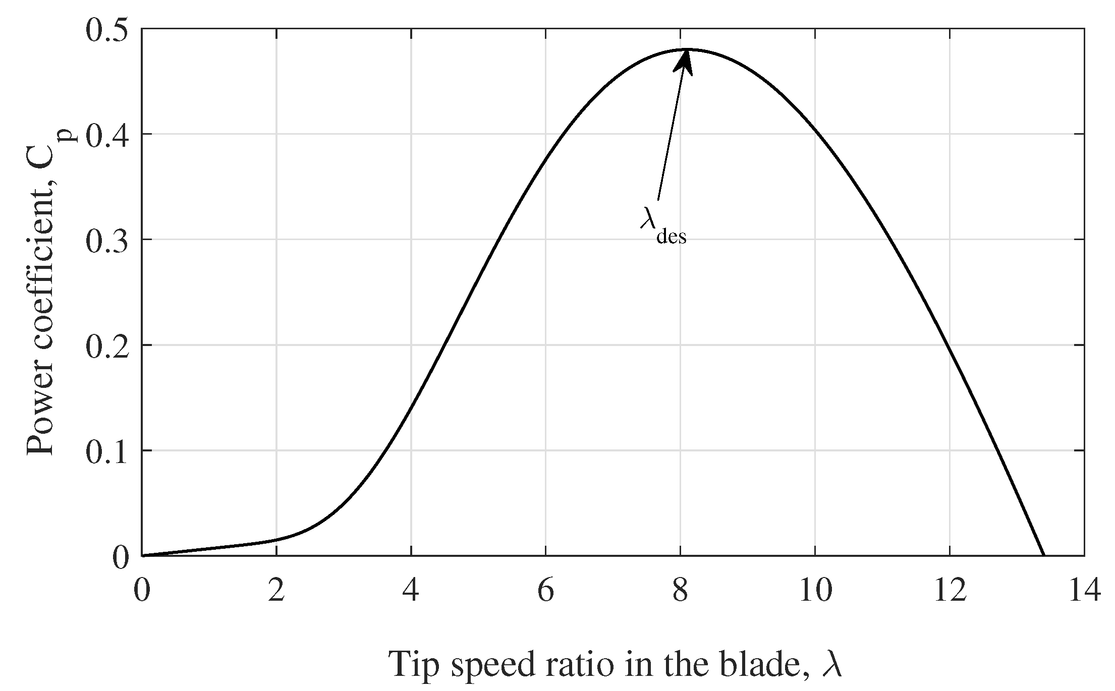
where is the wind density in kg/m2; is the turbine radius in m; is the power coefficient, which relates to the amount of wind energy that is transferred to the electrical generator, and is the wind speed in m/s, and the parameter relates to the tangential speed at the blade tip concerning the speed of the wind, yielding the following:
The power coefficient of the stall turbines can be approximated by the following nonlinear function [12,13]:
where
and the constants , , , , and correspond to a specific turbine design. The power coefficient function (4) is depicted in Figure 2, where the desired parameter , i.e., , defines the maximum power coefficient. Notice that the power coefficient is the only parameter that can be adjusted to maximize torque (2) and capture maximum wind energy.
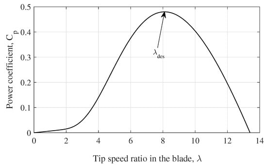
Figure 2.
Power coefficient.
The electromagnetic torque in (1), i.e., , at the coordinate frame, is defined as follows [14]:
where , , and , are the stator and rotor currents, respectively; P is the number of poles; and are the mutual inductance and stator inductance. These parameters are defined in the induction generator model in the following subsection.
3.2. Doubly Fed Induction Generator Electrical Model
The doubly fed induction generator is widely used in large-scale wind systems of variable speed. This generator is controlled through the rotor circuit using a bidirectional converter; meanwhile, the stator winding directly delivers a large amount of energy generated to the utility grid. The wind system operates in a bounded range of speed. When the system operates below synchronous speed, the power flows from the utility grid to the rotor circuit, and for the operation above the synchronous speed, the energy flow is reversed [15].
The doubly fed induction generator comprises a three-phase winding in the stator and another three-phase winding in the rotor. The voltage equation of the stator winding, assuming active convention for the stator currents, is as follows:
where , , and are the voltages, currents, and flux linkage vectors in the stator winding, and is the stator resistance per phase. Meanwhile, the stator flux linkage equation is defined by the following:
with
where is the rotor winding current vector; is the self-inductance of the stator winding per phase; is the mutual inductance between two phases of the winding stator; is the maximum mutual inductance between stator and rotor windings, and is the rotor angle displacement with respect to the x-axis.
On the other hand, the voltage equation of the rotor winding, assuming passive convention for the rotor currents, is as follows:
where and are the voltages and flux linkage vectors of the rotor winding, and is the rotor winding resistance per phase. The rotor flux linkage equation is defined by the following:
where is the self-inductance of the rotor per phase and is the mutual inductance between two phases of the rotor.
The doubly fed induction generator electrical model in the abc system described by Equations (7)–(10) is very complex because the mutual inductances between stator and rotor windings vary periodically with time (8). It is common to refer the electrical variables from the abc system to the dq0 coordinate system to obtain a simpler model of the doubly fed induction generator. The similitude transformation, also named the Park transformation, is described as follows [16]:
where denotes stator variables and denotes rotor variables. The phase-a axis of the stator variable is typically aligned with the d-axis of the stator variable, , in the dq0 coordinated system, which rotates according to the utility grid frequency; see Figure 3. It is important to note that the zero component of the dq0 system is null because the neutral line is not enabled. Therefore, the equivalent system in the dq is biphasic.
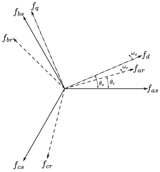
Figure 3.
The dq coordinate system.
Once the similitude transformation (11) is applied to the voltage and flux linkage equations of the stator windings (7) and (8), it yields the following:
where , and , , are the voltages, currents, and flux linkage vectors of the stator winding; is the rotor winding current vector, and is the electrical frequency of the utility grid.
In the same way, the similitude transformation (11) is applied to voltage and flux linkage equations of rotor windings (9) and (10). Thus, the following system is derived:
where , and and are the rotor voltages and flux linkage vectors, respectively; is the electrical frequency of the rotor circuit. Selecting the stator and rotor currents as state variables and regrouping the variables, the systems (12)–(15) define the following voltage equation:
Solving the derivative term in the voltage Equation (16), the doubly fed induction generator model in the dq coordinate system is obtained as follows [17]:
with
and
where and are the stator and rotor angular frequencies; is the coupling coefficient; and are the stator and rotor winding time constants; and are the stator are rotor winding resistances per phase; and are the stator self-inductance per phase and stator mutual inductance between two stator phases, respectively; and are the rotor self-inductance per phase and rotor mutual inductance between two rotor phases, respectively; is the maximum mutual inductance between stator and rotor windings. The electrical doubly fed induction generator model (18) is a perturbed linear system that has rotor speed as the mechanical input, , and as electrical inputs, the stator voltages and , and the electrical angular frequency ; meanwhile, the control inputs are the rotor voltages and .
The following relationships are used to refer the induction motor model parameters to equivalent electric circuit parameters [18]:
where and are the stator and rotor leakage inductances, respectively, is the magnetizing inductance and h is the turn ratio between stator and rotor windings.
3.3. Grid-Side Converter System
A wind system driven by a doubly fed induction generator requires two three-phase converter-type bridges in the “back-to-back” configuration due to variable power flow. The grid-side converter system comprises a DC link bus and a three-phase converter connected to the utility grid through an LCL filter, as pictured in Figure 1. The grid-side converter model is based on matching the input power from the electrical system to the DC output power of the converter, neglecting losses in both the LCL filter and converter and from the equilibrium voltage equation in terminals of the equivalent inductance of the LCL filter. Then, the grid-side converter model in the () three-phase system takes the following form:
where are the converter voltages; and are the phase voltages and currents of the utility grid; is the dc-bus voltage; is the output dc current; is the dc-bus capacitor; is the equivalent resistance; and is the LCL-filter equivalent inductance of the two inductors, without considering the capacitor for the purpose of reducing the order of the model.
The grid-side converter system is referenced to the dq0 coordinated frame, applying the similitude transformation (11) in system (19) with , considering that the zero component is null due to the neutral line not being enabled, resulting in the following form:
Solving the time derivative term in (20) and considering that when is referred, with respect to the of the in the similitude transformation (11), the grid-side converter model in the dq coordinate system results in [19] the following:
where and are the terminal voltages of the converter; , , , and are the currents and voltages of the utility grid, respectively. The grid-side converter model (21) is a nonlinear system; it has two inputs that can be controlled, and , which are uncoupled. Therefore, two outputs can be controlled through the currents and .
4. Converter Control System Design
This section describes the control system synthesis applied to wind systems tolerant to asymmetrical faults in the utility grid. Two independent control schemes are proposed: the rotor-side and grid-side converter controllers, with both including two controllers in parallel—one in a positive sequence and the other in a negative sequence. The main control objective of the rotor-side converter consists of controlling the electromagnetic torque of the induction generator to indirectly maximize the turbine power coefficient and, consequently, maximize the capture of wind energy. Meanwhile, the main control objective of the grid-side converter consists of the voltage regulation of the DC bus so the AC/DC/AC converter works properly.
4.1. Generator Electromagnetic Torque Control System
The main control objective of the rotor-side converter applied to a wind system driven by a doubly fed induction generator is to continuously achieve the maximum capture of wind energy by controlling the electromagnetic torque of the generator. This objective is met by maximizing the power coefficient in the turbine torque Equation (2). The control system synthesis is based on the wind system models (1) and (18). As a first step, the output variables to be controlled are selected. As can be seen in the induction generator model (18), two inputs are identified that can be controlled: the rotor voltages and . Consequently, the two output variables to control are the electromagnetic torque of the generator defined in (6) and the reactive power consumed via stator winding, whose definition is [14] as follows:
where is the stator voltage at the d-axis and is the stator current at the q-axis.
The reference functions represent the second step in solving trajectory tracking. When defining the reference torque function, consideration should be placed on achieving the control goal of maximizing wind energy capture while avoiding sudden torsional forces on the shaft. Firstly, a desired speed reference is defined from (3) as follows:
where sets the maximum power coefficient (4) in the turbine torque (2), and consequently the wind energy capture is maximized. Secondly, a speed error variable is defined as follows:
whose dynamic is defined through a stable asymptotic dynamic movement to avoid sudden torsional forces on the shaft. Involving (23) and (1) into the speed error dynamics of (24) results in the following:
where defines the decreased rate of the velocity error. Finally, by solving the generator torque in (25), it can be defined as the torque reference function that maximizes the wind energy capture, which is as follows:
The reactive power reference function can be established from the desired stator power factor and the active power that crosses the air gap [20]. Then, the reactive power reference function can be defined in the following form:
where is the synchronous speed and is the desired stator power factor.
As a third step in the controller design process, an equivalent system is established by using tracking error variables as new variables. A tracking error is defined as follows:
where
whose dynamics are as follows:
Thus, substituting the corresponding state equation of the induction generator model (18) into (29), the equivalent system takes the following form:
where is a nonlinear term, and it can be modeled as a disturbance; meanwhile, the matrix coefficient of the control input is as follows:
System (30) is the first order, with the input vector being coupled to the stator and rotor currents as state variables. Therefore, a new system is proposed to decouple the input vector as follows:
where
The dynamics of the new system, with the input vector being decoupled, take the following form:
Then, as final step, the super-twisting control law is applied to system (34) to force its movement to the origin [21], obtaining the following representation:
where the diagonal matrices and have values high enough to cancel the disturbance, , forcing both systems (32) and (34) toward the origin in finite time; therefore, the tracking error vector (28) is forced to zero in finite time, too [22]. Thus, the control objective is achieved by tracking the reference torque to maximize the wind energy capture and regulate the stator reactive power to achieve the desired power factor.
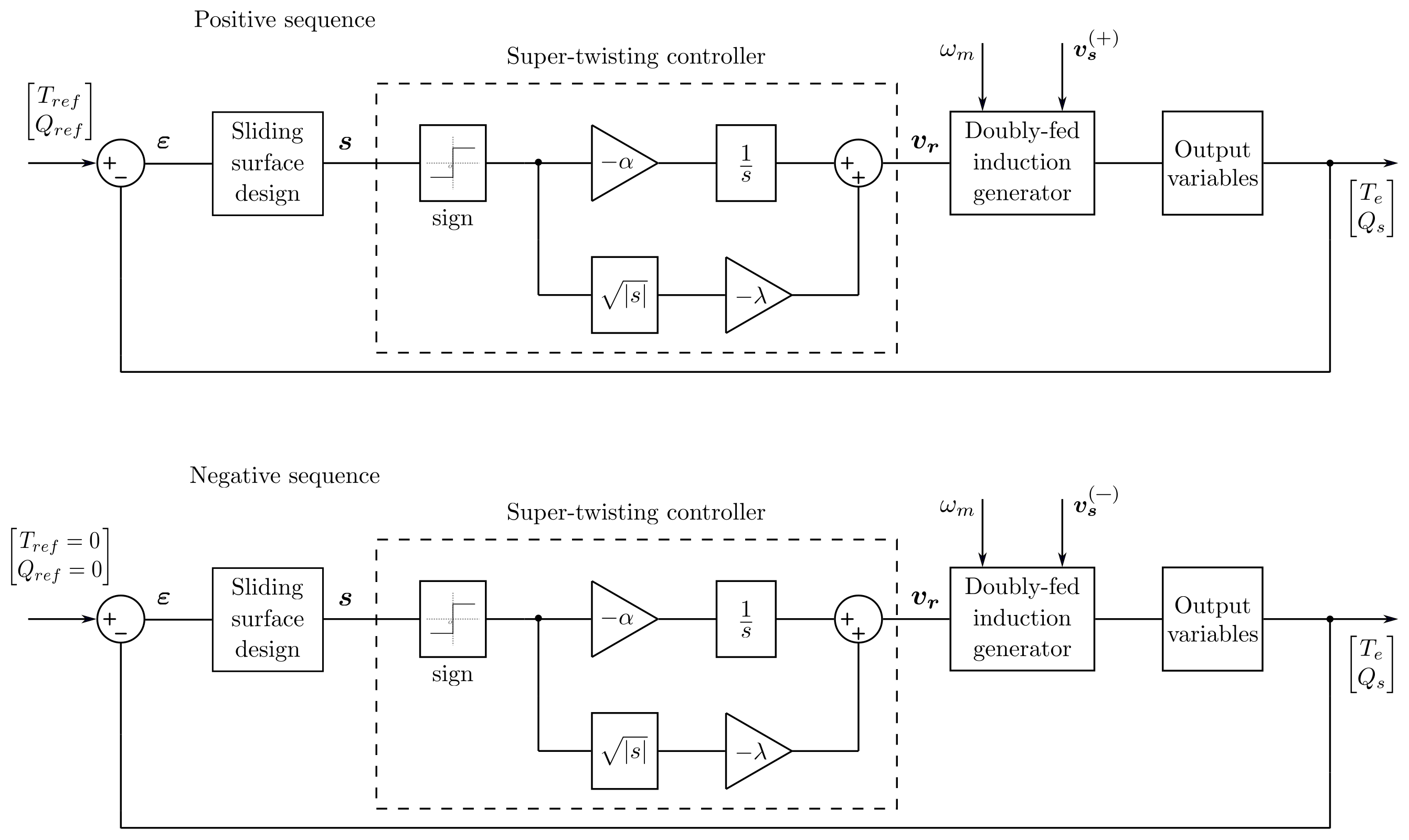
If an asymmetric failure occurs in the utility grid, the voltages between phases become unbalanced. This event produces oscillations in the voltages with the consequent increase and distortion of the stator and rotor currents, which occurs in the system. Therefore, in the time domain, this project proposes applying the symmetrical component transformation to the line-to-line voltages to avoid the oscillations on voltages and configure two control systems, one being a positive sequence controller to meet the control goals of the wind system, and another being a negative sequence controller to cancel the reversed torque and negative reactive power produced by the negative sequence variables. Figure 4 shows the block diagram involving both controllers.
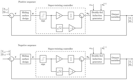
Figure 4.
Proposed control scheme.
4.2. Grid-Side Converter Controller
The main control objective of the grid-side converter consists of maintaining the DC-bus voltage in a specific value so that the rotor-side converter performs well for the bidirectional power flow between the rotor winding and the utility grid occurring appropriately [23]. The controller design is based on the grid-side converter model, which is given in (21). As the first step, the output variables to be controlled are selected. As can be seen in (21), the grid-side converter system has two inputs that can be controlled, which are the inverter voltages and . As a second output variable, the reactive power flow between the utility grid and the rotor circuit can also be controlled. As a second step, the reference values are defined to solve the regulation problem. The reference voltage of the DC bus is as follows:
where is the line-to-line voltage in the utility grid or the line-to-line voltage of the primary winding when a step-up transformer is used. Meanwhile, the reference value to reactive power flowing via the rotor circuit is as follows:
where this reference value sets a unitary factor power. As a third step in the controller design process, an equivalent system is established using tracking error variables as new variables. Firstly, an error variable of voltage tracking is defined as follows:
where is the voltage reference to the DC-bus voltage . Applying the linearization block control technique [24], the stable dynamics of the voltage tracking error (38) are defined involving the corresponding state equation of grid-side converter system (21), resulting in the following:
From the first-order system (39), and solving for , a current reference is defined as follows:
Then, the second error variable—as the current tracking error—is defined by the following:
where the dynamic is defined involving the corresponding state equation of grid-side converter system (21), which results in the following:
The third error variable is defined as the tracking error of the reactive power, computed in the following form:
whose dynamics are defined, involving the corresponding state equation of grid-side converter system (21), in the following form:
Joining Equations (39), (42), and (44), the equivalent systems to the grid-side converter (21) have the following presentation:
Then, as final step, the super-twisting control law is applied to the new system (45) to force the movement of the variables and to the origin [25], obtaining the following representation:
The super-twisting control law cancels the external disturbances [25] in the new system (46). Specifically, the control input at the d-axis cancels the non-linearities and disturbances, and this input forces the movement of the sliding surface, , toward the origin, the second equation of (46). Achieving this, the current reaches its reference value (41), and consequently, the DC-bus voltage error has asymptotic movement toward the origin in finite time, the first equation of (46). On the other hand, the control input at the q-axis cancels the external disturbances and produces the asymptotic movement of the sliding surface to zero; then, the reactive power reaches its reference value (43) in finite time.
When an asymmetric failure occurs in the utility grid, oscillations in the voltages, along with an increase and distortion in the stator and rotor currents, are observed in the system. By applying symmetrical components to the line-to-line voltages in the time domain and configuring the positive sequence controller to meet the control objectives of the grid-side converter, and the negative sequence controller to cancel out the negative DC bus voltage, and the negative reactive power produced by the negative sequence variables, the grid-side converter system can maintain its operation when a failure occurs in the electrical grid [26].
5. Real-Time Symmetrical Components
The transformation of symmetrical components for analyzing unbalanced three-phase systems is typically applied. The unbalanced three-phase system can be represented by the sum of three symmetrical systems: positive, negative, and zero sequences, as follows [27]:
where , , and denote mean positive, negative, and zero sequence components, respectively. To obtain the sequence signals in phase-, the following transformation is applied:
where , with . To reduce the calculation complexity of the complex operator a, this can be expressed as follows:
then, substituting (49) in (48) results [28] in the following:
Once the sequence signals are defined in phase-, the phase- and phase- sequence phase signals are obtained through the following transformations:
and
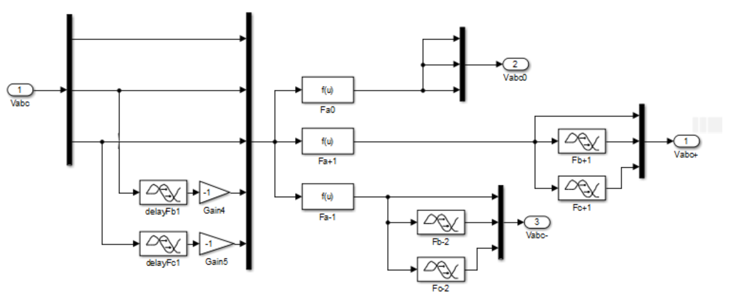
The complex operators in (50)–(52) are represented through the time delay function of Simulink/Matlab® R2016a using a frequency of 60 Hz. Finally, the symmetrical component transformation applied to unbalanced three-phase voltages is represented in the scheme shown in Figure 5.
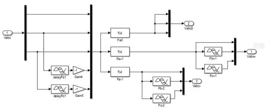
Figure 5.
Real time symmetrical component scheme.
6. Simulation Results
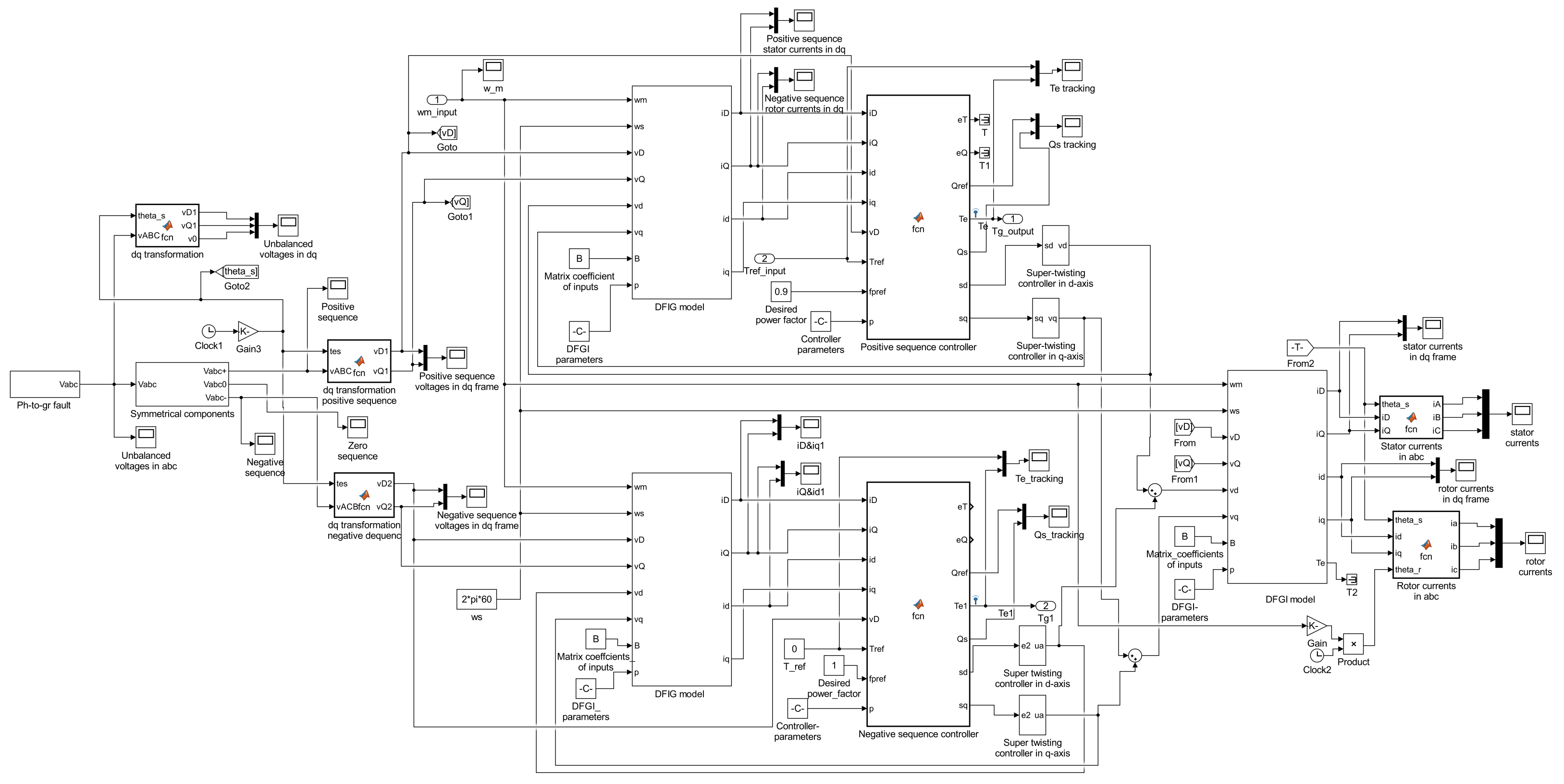
The simulated system is formed by the turbine mechanical model and the following systems in the coordinate frame: the doubly fed induction generator model, the rotor-side converter system, and the utility grid. The parameters of the simulated system are indicated in Table 1 and Table 2. The turbine parameters are presented in Table 1 [29]; Table 2 presents the nameplate data and the parameters of the induction generator. Subsequently, the proposed control system performance is presented through figures in positive and negative sequences for two types of asymmetric faults that occur in the utility grid. In the performance analysis of the wind system, the solid-state inverters are not considered due to the variables in the frame being DC signals. The system is simulated in Simulink/Matlab®, with a fixed-step sample time of 100 μs. The system is simulated with a fixed-step sample time of 100 μs in Simulink/Matlab® using the ordinary differential equation method: ode4 (Runge Kutta), as the solver; Figure 6 presents the system implemented in Matlab/Simulink®.

Table 1.
Wind turbine parameters.
Table 2.
Nameplate data and doubly fed induction generator parameters.

Figure 6.
Source block program in Simulink/Matlab®.
Two types of asymmetrical faults in the utility grid are simulated in the three-phase system. One fault is phase to ground and another is phase to phase; in both faults, the voltage level and the current waveform depend on the grounding system and fault impedance.
6.1. Performance of the Wind System Controller under a Phase to Ground Fault in the Utility Grid
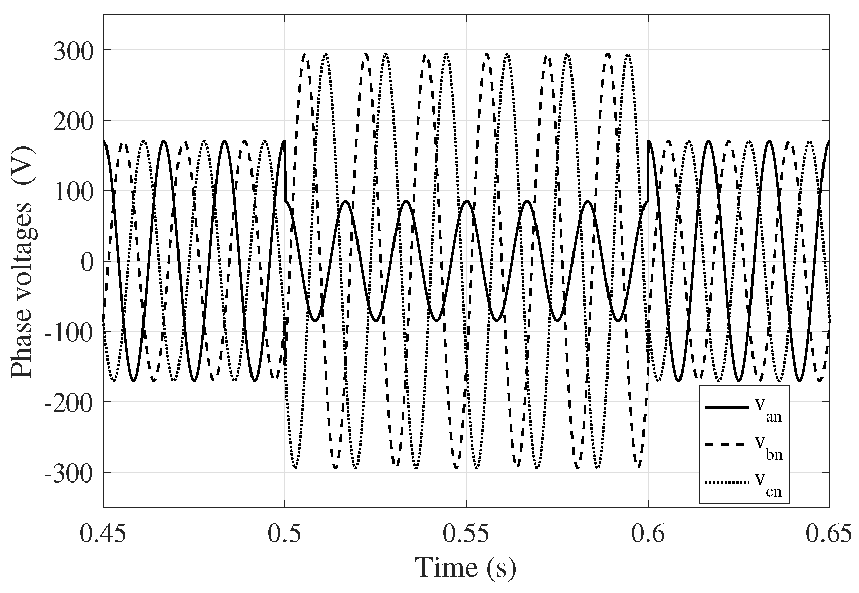
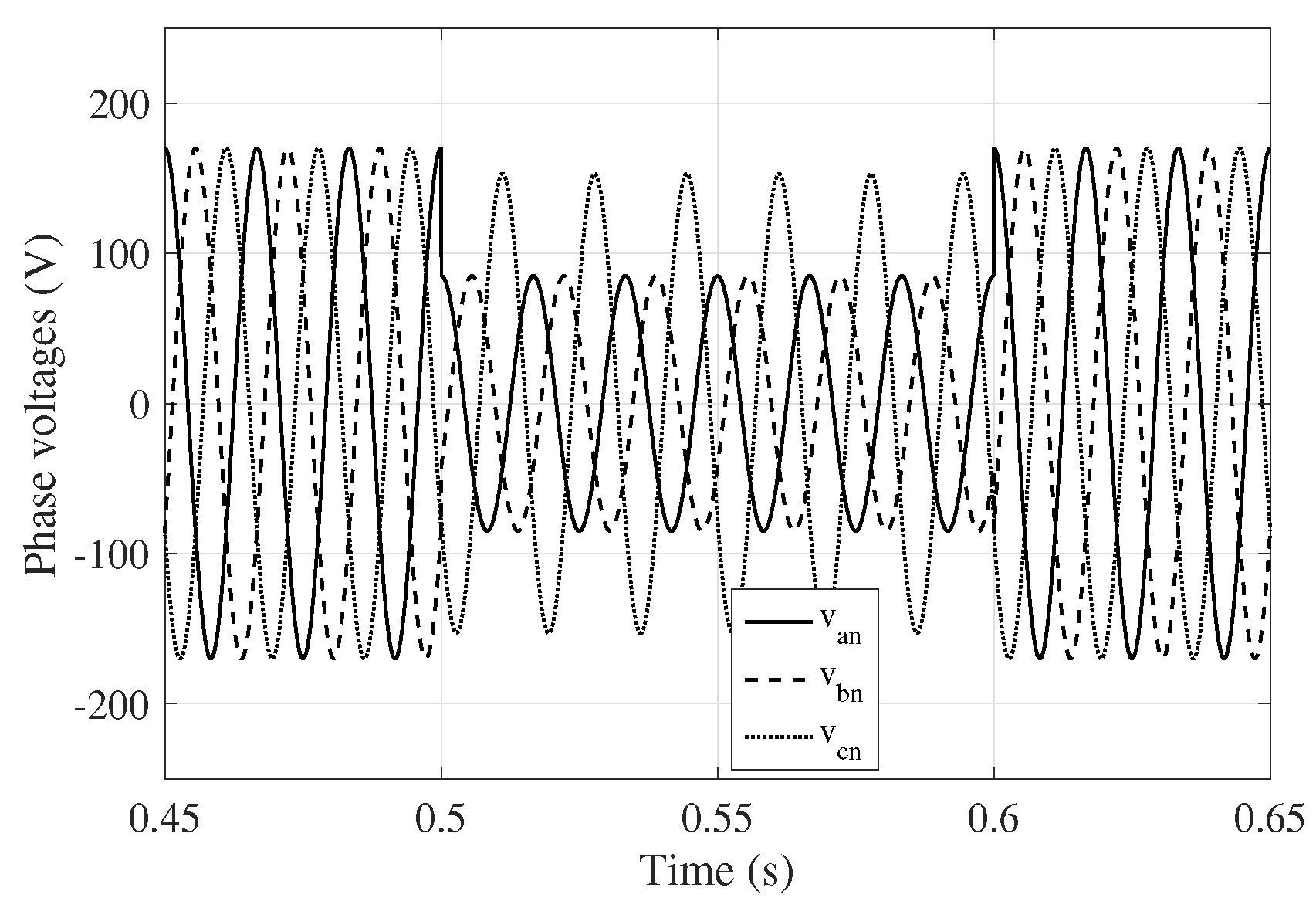
A phase to ground fault can occur on the generator terminals or the medium-voltage bus; in both cases, the faults have similar behavior [30]. Ideally, at the point of failure, and . Nevertheless, the phase voltage drops to a value that depends on the fault impedance; meanwhile, the other two-phase voltages, and , can have an overvoltage whose value can be the line-to-line voltage due to the grounding wire’s resistance, leakage, and coupling capacitance in the ground connection. The failure approach set above is simulated in Simulink/Matlab®; at the beginning of the simulation, all phase voltages are 120 V rms, and the phase to ground fault is presented at s, causing phase voltage to decrease its magnitude to 0.5 pu; meanwhile, the other two-phase voltages, and , increase the magnitude of the line-to-line voltage. At s, the fault is cleared, and all phase voltages are restored, as shown in Figure 7.
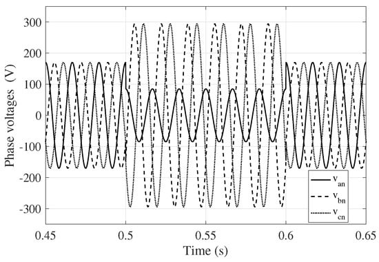
Figure 7.
Utility grid phase voltages in a phase to ground fault.
6.1.1. Performance of a Non Tolerant Fault Controller in a Phase to Ground Fault
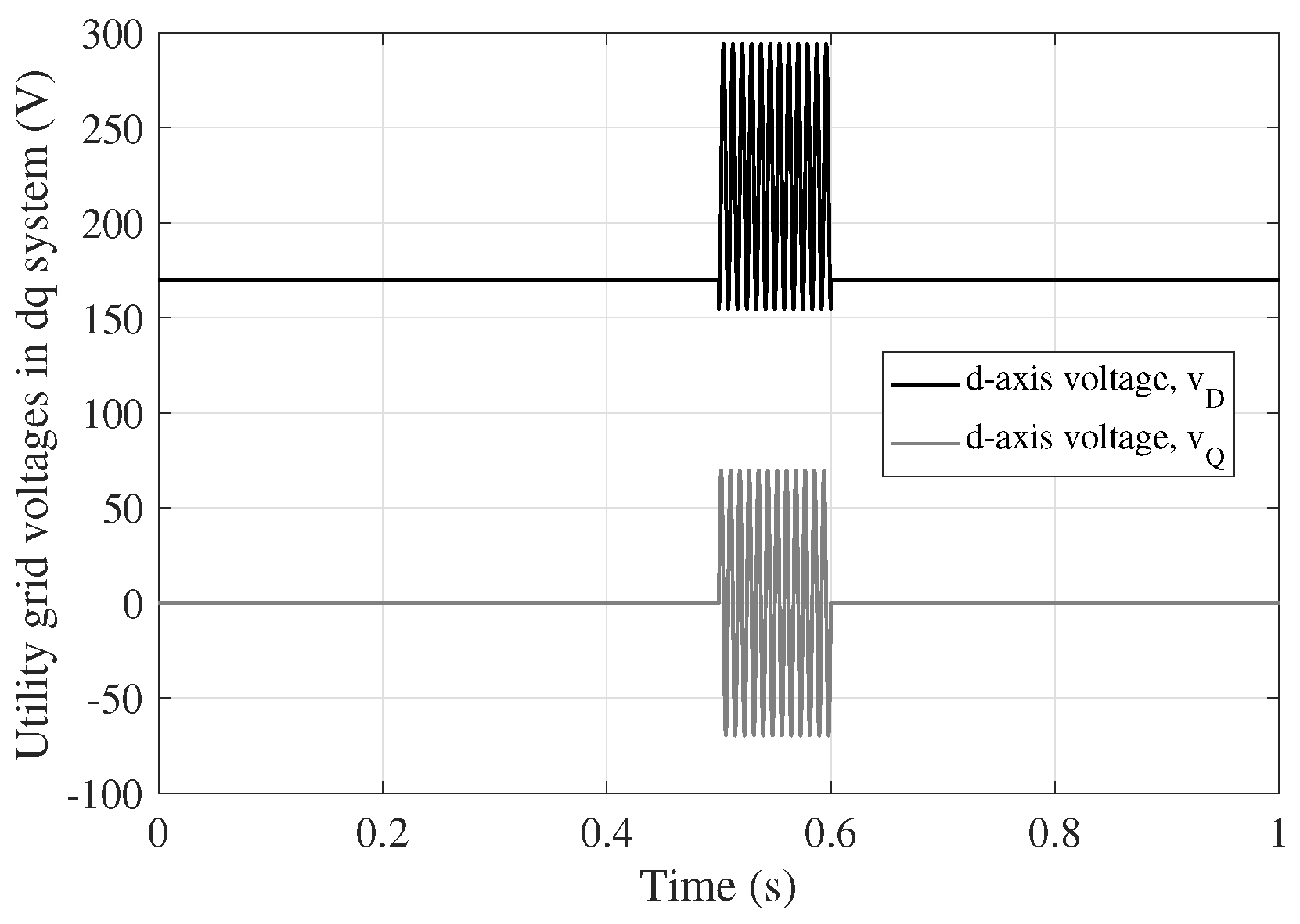
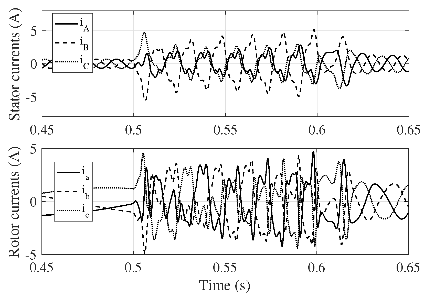
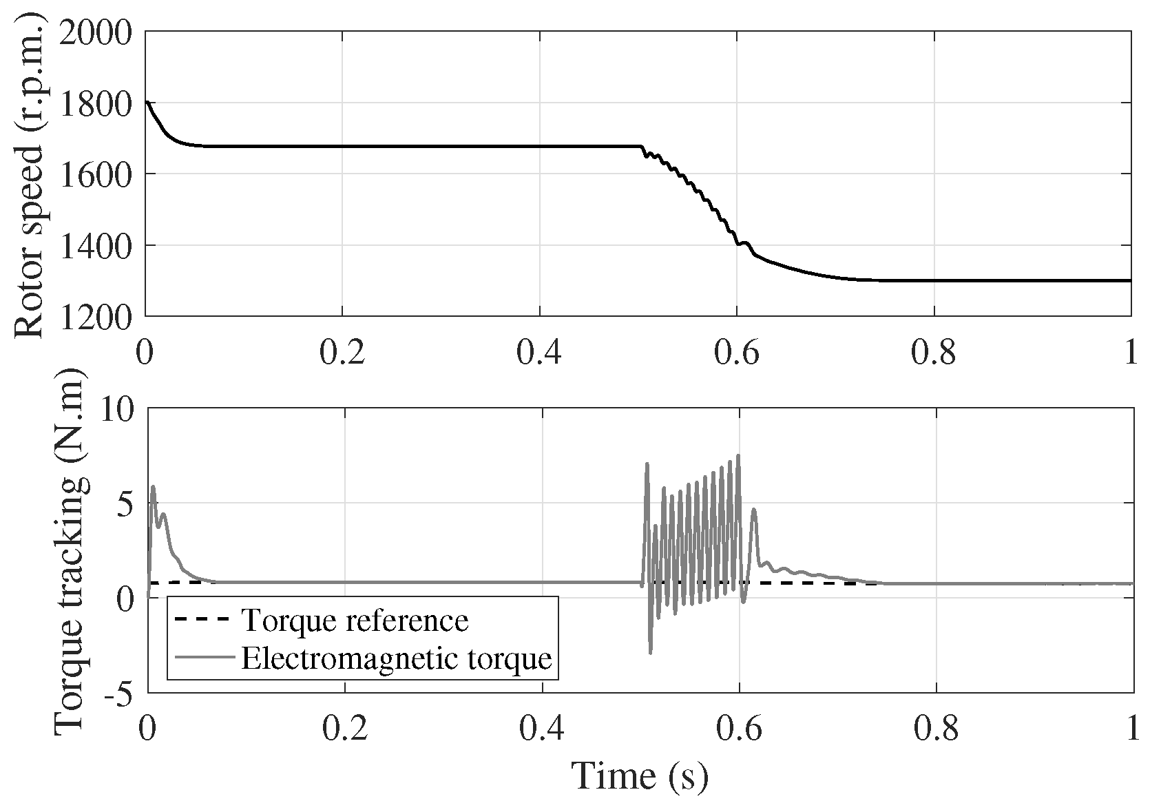
Under the conditions set in the phase to ground fault and the induction generator operating in a controlled form without including the proposed controller, the performance of the wind system is pictured in Figure 6, Figure 7 and Figure 8. Stator voltages and have oscillations in steady state during the time range in which the fault is presented, as shown in Figure 8. The oscillation frequency is 120 Hz. The stator and rotor currents of the induction generator are distorted, out of phase, and increase in value, as shown in Figure 9, which represents an overload condition for the generator. The rise and distortion of the currents cause high oscillations in the electromagnetic torque developed by the generator, with a consequent decrease in the rotor speed of 400 r.p.m., approximately, as pictured in Figure 10. The torque oscillation causes stress in the mechanical system.
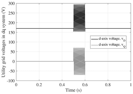
Figure 8.
Utility grid voltages for a phase to ground fault.

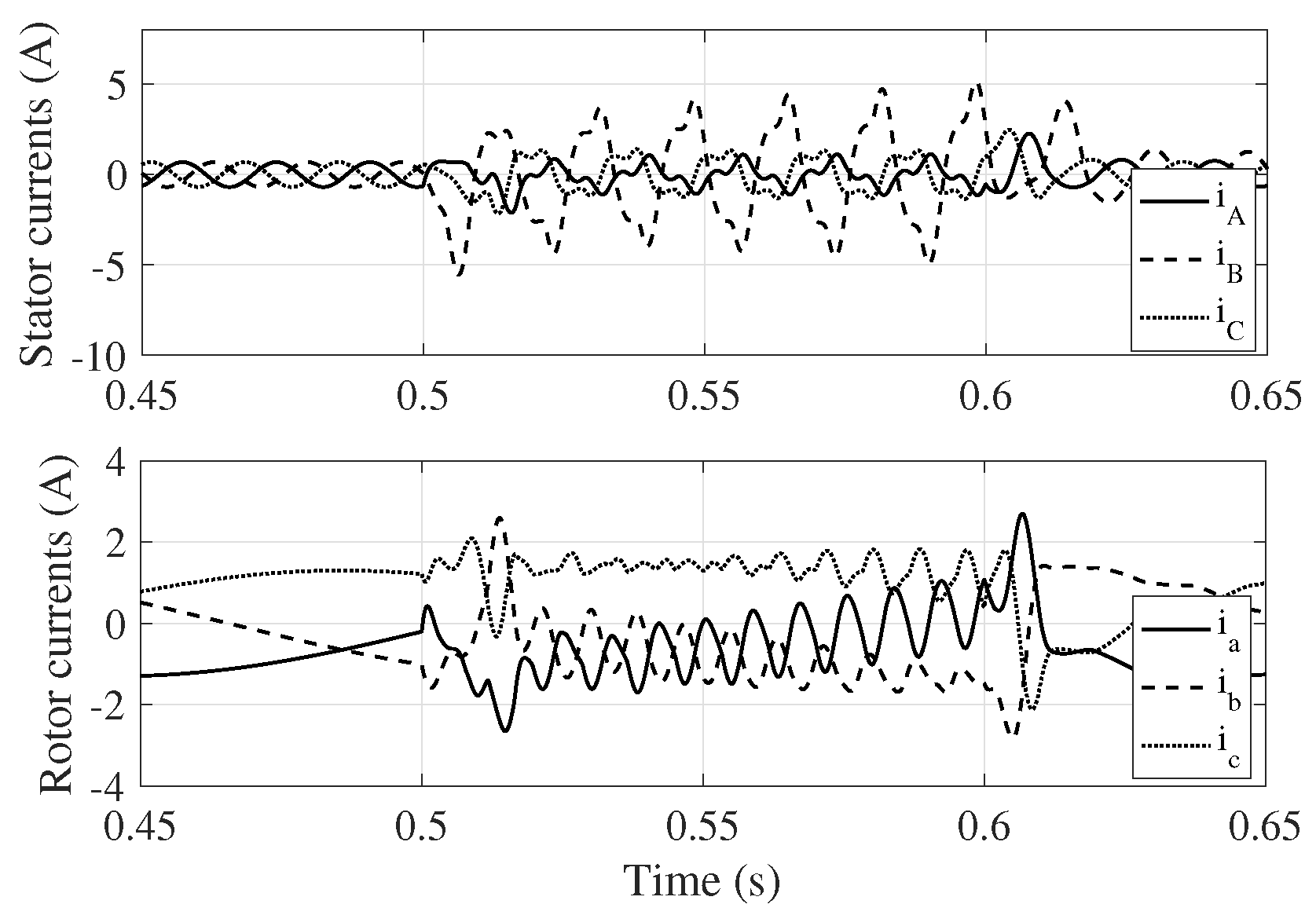
Figure 9.
Stator and rotor currents under a phase to ground fault.
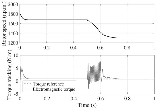
Figure 10.
Rotor speed and torque tracking under a phase to ground fault.
6.1.2. Performance of the Fault-Tolerant Controller Proposed in a Phase to Ground Fault
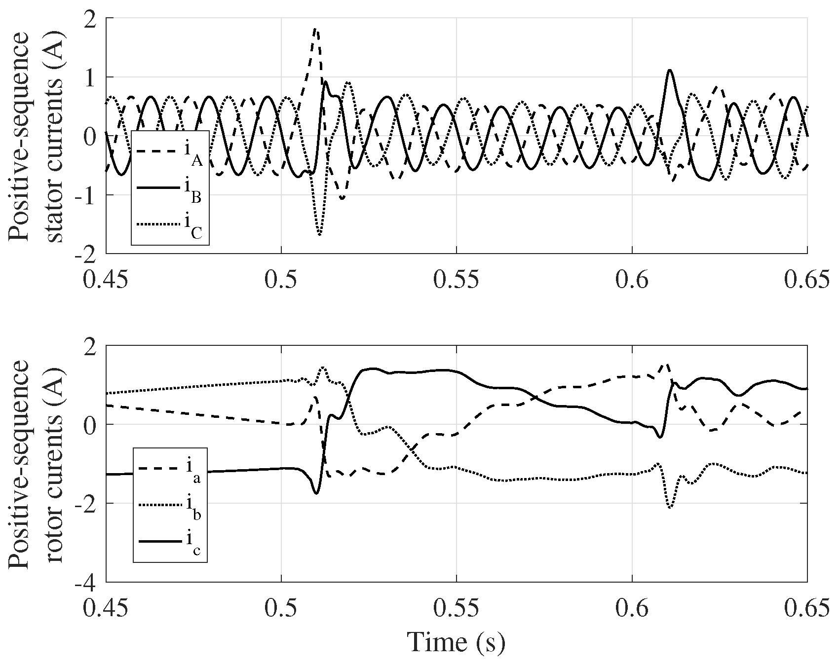
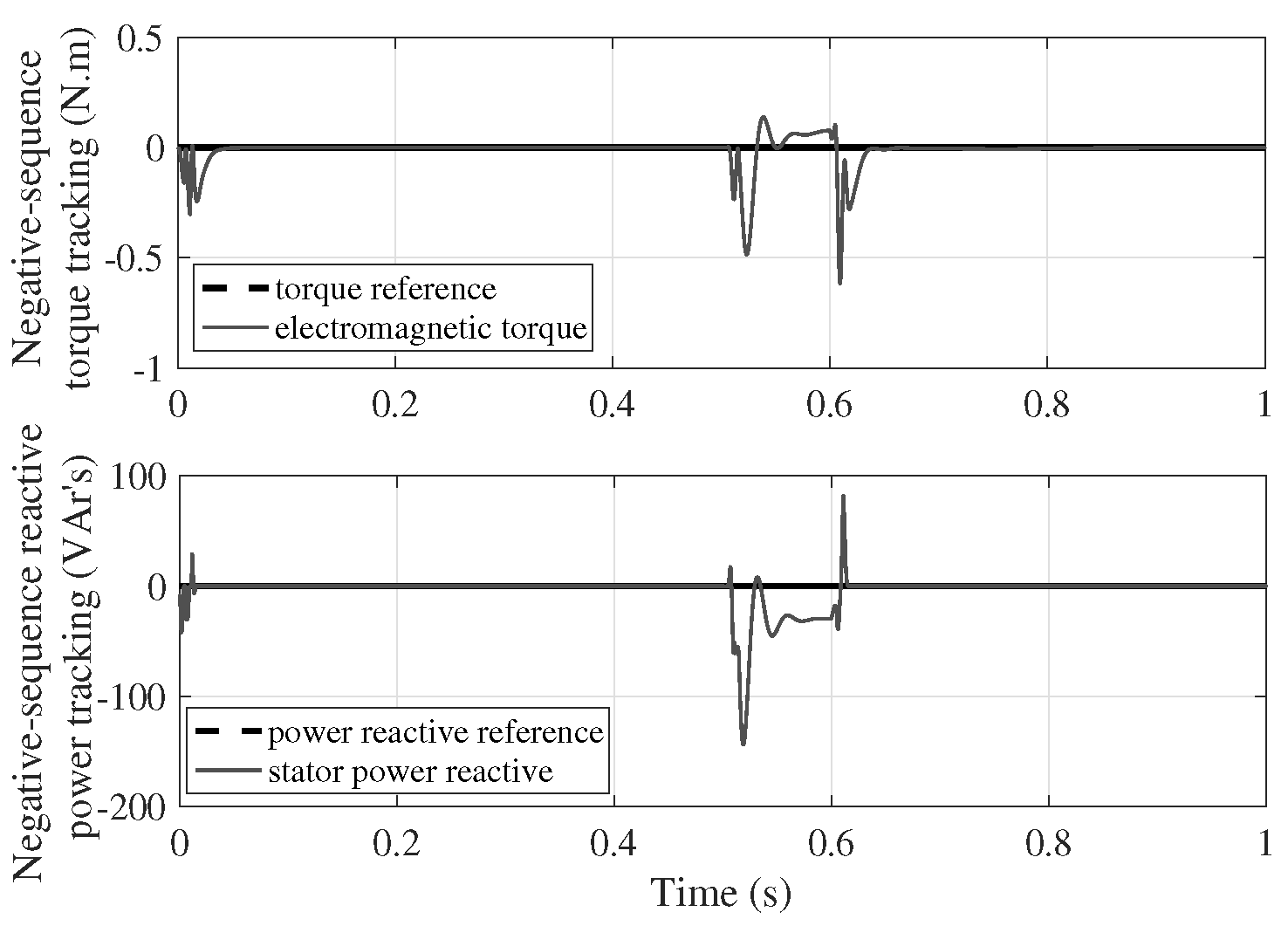
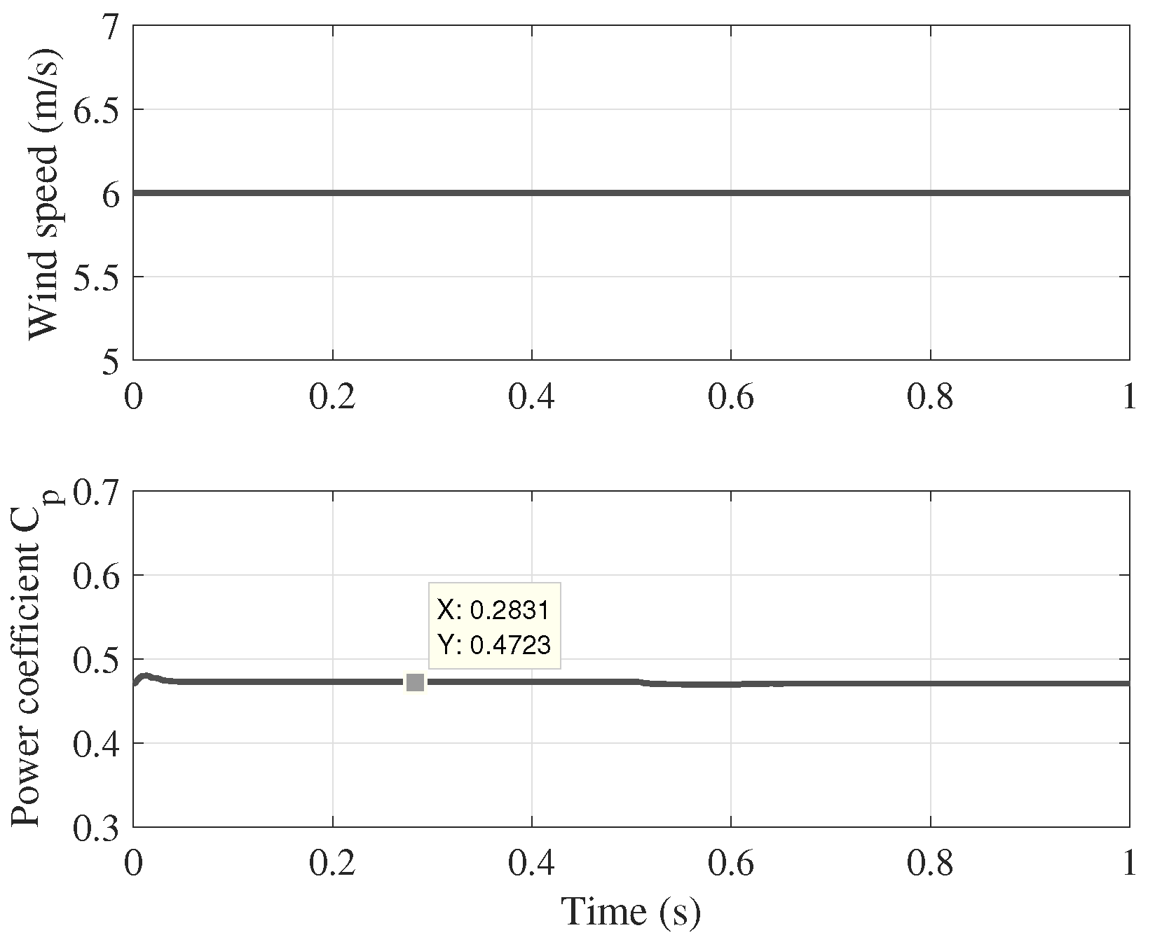
Once the generator performance is analyzed in phase to grid failure conditions in the utility grid, without the use of the proposed controller, the analysis is conducted by applying the symmetrical component transformation to the unbalanced voltages of the utility grid caused by the fault. Then, these voltages are transformed into coordinate frames for positive and negative sequences. These voltages are pictured in Figure 11. It is important to note that these voltages do not have oscillations in a steady state. Consequently, the stator and rotor currents now do not have high values, as pictured in Figure 12. Figure 13 shows torque and reactive power tracking in a positive sequence. The electromagnetic torque of the induction generator tracks the torque reference, which maximizes the wind energy in the turbine. Meanwhile, the reactive power tracks its reference, setting a lagging power factor of 0.9. The tracking of the electromagnetic torque and reactive power in the negative sequence is pictured in Figure 14. The electromagnetic torque in the negative sequence tracks the zero value as a torque reference to cancel out the negative torque that overloads the generator. Meanwhile, the reactive power in a negative sequence tracks a zero value of its reference to define a unity power factor. Finally, in Figure 15, the input wind speed and power coefficient are pictured. It is important to note that when the torque reference is tracked (26), the power coefficient (4) consistently remains at its maximum value of 0.47.
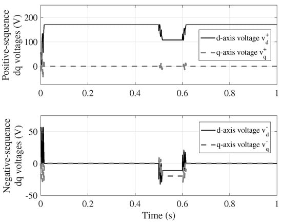
Figure 11.
Positive and negative sequence stator voltages for a phase to ground fault.

Figure 12.
Positive sequence stator and rotor currents under a phase to ground fault.
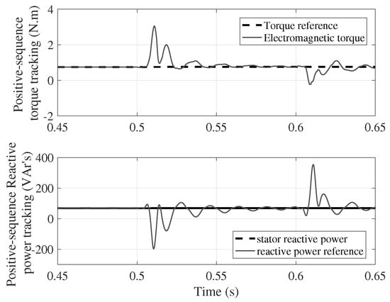
Figure 13.
Positive sequence torque and reactive power tracking for a phase to ground fault.
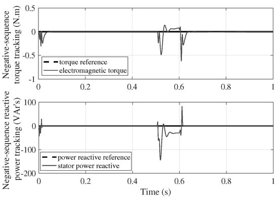
Figure 14.
Negative sequence torque and reactive power tracking in a phase to ground fault.
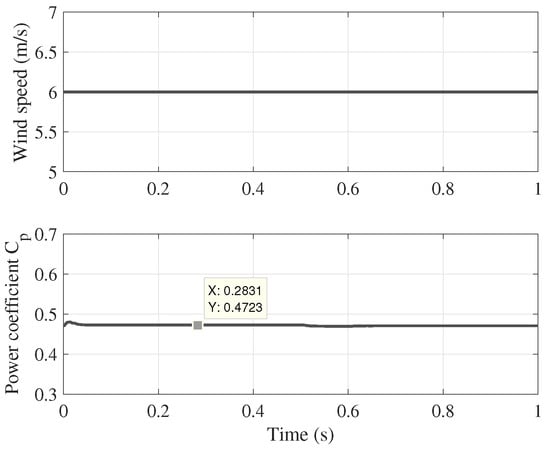
Figure 15.
Input wind speed and power coefficient.
6.2. Phase to Phase Fault
This type of fault is presented at generator terminals (phase a to phase b) at s and cleared at s [30]. Ideally, , , and at the point of failure. The phase voltages and decrease considerably, and in phase c, the voltage has a marginal drop. At the beginning of the simulation of this fault condition, all phase voltages are 120 Vrms, and the phase-to-phase fault is presented at 0.5 s, causing both phase a and b voltages to decrease their value to 0.5 pu; meanwhile, the phase c voltage decreases to the marginal value of 0.9 pu. The phase to phase fault is cleared at s, and all phase voltages are restored, as shown in Figure 16.
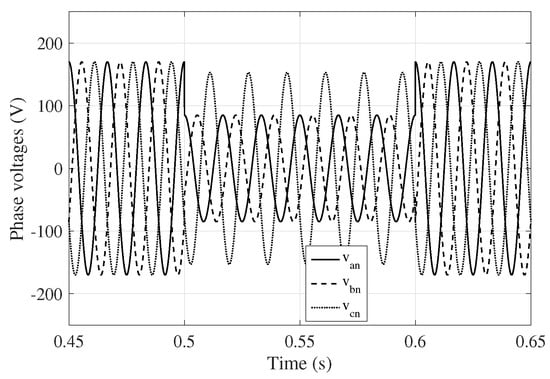
Figure 16.
Utility grid phase voltages in a phase to phase fault.
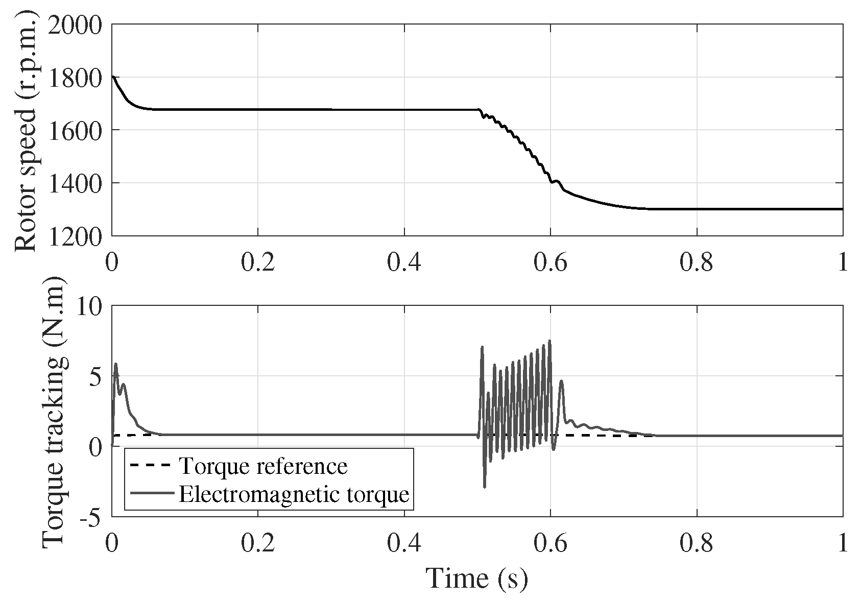
In the phase to phase fault scenario, both stator and rotor currents experience an increase in magnitude, become distorted, and undergo a phase shift with respect to the other phases, as shown in Figure 17. The distortion and increase in both stator and rotor currents cause an increase in the electromagnetic torque, resulting in a consequent decrease in the rotor speed, see Figure 18. The positive and negative sequence variables in both types of faults have a very similar performance; therefore, we report only the symmetrical component results for the phase to ground fault.
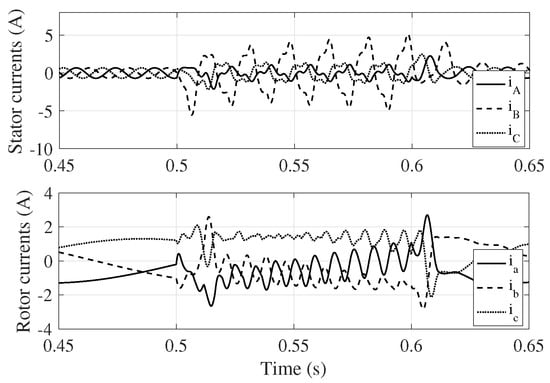
Figure 17.
Stator and rotor currents under a phase to phase fault.
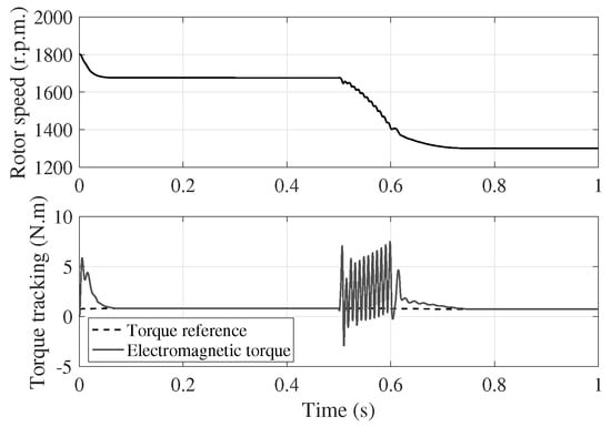
Figure 18.
Rotor speed and electromagnetic torque under a phase to phase fault.
7. Discussion
This project presents a small-scale model of a wind energy system that can operate even during fault conditions. Two controllers are suggested to maintain generator operation during electrical network failure conditions: one for the positive sequence and one for the negative sequence. The design of the converter controller relies on the models of both the wind turbine and the doubly fed induction generator. The induction generator model is linear and can handle external disturbances, such as limited inputs to the system, the rotor speed, voltages from the utility grid, and angular frequency. The model used in this system has linear characteristics, allowing the superposition principle to be applied. This means that one control input can be in a positive sequence while the other can be in a negative sequence. The positive sequence controller on the rotor-side converter controls the generator’s electromagnetic torque, which maximizes the amount of wind energy captured by the turbine. Meanwhile, the negative sequence controller cancels the reverse electromagnetic torque that is created by any electrical faults that may occur. It is important to highlight the implementation of the symmetric component transformation in the time domain of the voltages established during an asymmetric failure in the utility grid. Usually, this transformation is performed in the frequency domain. The results demonstrate the control system’s effectiveness by adding a positive sequence control input to track the torque reference and a negative sequence control input to cancel the reversed electromagnetic torque produced by the fault. As part of the second stage, the challenge is to implement a fault-tolerant emulated wind system using electrical machines, specifically a DC motor-doubly fed induction generator, due to the importance and unique characteristics of the proposed controller.
8. Conclusions
This research paper discusses a control system that was designed to be applied to wind energy systems. The system is tolerant to asymmetrical faults that may occur in the utility grid. To achieve this, two independent control schemes are proposed: the rotor-side converter controller and the grid-side converter controller. Each of these controllers includes two parallel controllers, one for the positive sequence and the other for the negative sequence. When using the rotor-side converter, two controllers serve different purposes. The positive sequence controller ensures that the generator’s torque reference is accurately tracked, allowing for maximum wind energy capture. Additionally, it regulates the reactive power flow through the stator winding. On the other hand, the negative sequence controller is responsible for canceling out any reversed electromagnetic torque produced by currents in the negative sequence. It also cancels out any negative reactive power flow through the stator winding. This ensures that the generator does not operate in overload conditions. The grid-side converter has two controllers: the positive sequence controller regulates the DC bus voltage and the reactive power to achieve a power factor of one for the rotor circuit. The negative sequence controller cancels out the negative voltage of the DC bus and cancels out the reactive power in the negative sequence flowing in the rotor circuit. It is important to highlight that the symmetrical component transformation is applied to the time domain. By utilizing this tool, it is possible to examine an asymmetrical fault in the grid utility as well as its impact on the performance of the wind system. In the project’s next phase, the strategies proposed in this research will be implemented in real time.
Author Contributions
O.M. contributed to the design of the controllers, programmed the simulation of the models and controllers in Simulink/Matlab®, and wrote some sections of the paper. D.D. configured the two types of asymmetrical fault models (phase to ground fault and phase to phase fault) in Simulink/Matlab®, and wrote the problem statement section. A.C. wrote the introduction section and synthesized the controllers in positive and negative sequences. M.M. designed the paper’s figures and prepared the paper edition in Latex. J.I.H. wrote some sections of the paper and improved the English writing. P.E. verified and refined the controller design applied to the torque control of the doubly fed induction generator in positive and negative sequences. All authors have read and agreed to the published version of the manuscript.
Funding
This research received no external funding.
Institutional Review Board Statement
Not applicable.
Informed Consent Statement
Not applicable.
Data Availability Statement
No new data were created or analyzed in this study. Data sharing is not applicable to this article.
Conflicts of Interest
The authors declare no conflict of interest.
References
- Mahadanaarachchi, V.P. Fault Analysis and Protection of Doubly Fed Induction Generator-Based Wind Farms; Oklahoma State University: Stillwater, OK, USA, 2009. [Google Scholar]
- Ouyang, J.; Zheng, D.; Xiong, X.; Xiao, C.; Yu, R. Short-circuit current of doubly fed induction generator under partial and asymmetrical voltage drop. Renew. Energy 2016, 88, 1–11. [Google Scholar] [CrossRef]
- Nazir, M.S.; Wang, Y.; Mahdi, A.J.; Sun, X.; Zhang, C.; Abdalla, A.N. Improving the performance of doubly fed induction generator using fault tolerant control—A hierarchical approach. Appl. Sci. 2020, 10, 924. [Google Scholar] [CrossRef]
- Tilli, A.; Conficoni, C.; Hashemi, A. An effective control solution for doubly-fed induction generator under harsh balanced and unbalanced voltage sags. Control Eng. Pract. 2019, 84, 172–182. [Google Scholar] [CrossRef]
- Jabbour, N.; Tsioumas, E.; Mademlis, C.; Solomin, E. A highly effective fault-ride-through strategy for a wind energy conversion system with a doubly fed induction generator. IEEE Trans. Power Electron. 2020, 35, 8154–8164. [Google Scholar] [CrossRef]
- El-Naggar, A.; Erlich, I. Analysis of fault current contribution of Doubly-Fed Induction Generator Wind Turbines during unbalanced grid faults. Renew. Energy 2016, 91, 137–146. [Google Scholar] [CrossRef]
- Hachicha, F.; Krichen, L. Rotor power control in doubly fed induction generator wind turbine under grid faults. Energy 2012, 44, 853–861. [Google Scholar] [CrossRef]
- Cardenas, R.; Peña, R.; Alepuz, S.; Asher, G. Overview of control systems for the operation of DFIGs in wind energy applications. IEEE Trans. Ind. Electron. 2013, 60, 2776–2798. [Google Scholar] [CrossRef]
- Munteanu, I.; Bratcu, A.I.; CeangĂ, E.; Cutululis, N.A. Optimal Control of Wind Energy Systems: Towards a Global Approach; Springer: Berlin/Heidelberg, Germany, 2008; Volume 22. [Google Scholar]
- Abad, G.; Lopez, J.; Rodriguez, M.; Marroyo, L.; Iwanski, G. Doubly Fed Induction Machine: Modeling and Control for Wind Energy Generation; John Wiley & Sons: Hoboken, NJ, USA, 2011. [Google Scholar]
- Burton, T.L.; Jenkins, N.; Bossanyi, E.; Sharpe, D.; Graham, M. Wind Energy Handbook; John Wiley & Sons: Hoboken, NJ, USA, 2021. [Google Scholar]
- Voltolini, H.; Granza, M.H.; Ivanqui, J.; Carlson, R. Modeling and simulation of the Wind Turbine Emulator using induction motor driven by torque control inverter. In Proceedings of the 2012 10th IEEE/IAS International Conference on Industry Applications, Fortaleza, Brazil, 5–7 November 2012; pp. 1–6. [Google Scholar]
- Sahoo, N.; Satpathy, A.; Kishore, N.; Venkatesh, B. Dc motor-based wind turbine emulator using LabVIEW for wind energy conversion system laboratory setup. Int. J. Electr. Eng. Educ. 2013, 50, 111–126. [Google Scholar] [CrossRef]
- Leonhard, W. Control of Electrical Drives; Springer Science & Business Media: Berlin/Heidelberg, Germany, 2001. [Google Scholar]
- Wu, B.; Lang, Y.; Zargari, N.; Kouro, S. Power Conversion and Control of Wind Energy Systems; John Wiley & Sons: Hoboken, NJ, USA, 2011; Volume 76. [Google Scholar]
- Park, R.H. Two-reaction theory of synchronous machines generalized method of analysis-part I. Trans. Am. Inst. Electr. Eng. 1929, 48, 716–727. [Google Scholar] [CrossRef]
- Morfin, O.A.; Ruiz-Cruz, R.; Loukianov, A.G.; Sánchez, E.N.; Castellanos, M.; Valenzuela, F.A. Torque controller of a doubly-fed induction generator impelled by a DC motor for wind system applications. IET Renew. Power Gener. 2014, 8, 484–497. [Google Scholar] [CrossRef]
- Krause, P.C.; Wasynczuk, O.; Sudhoff, S.D.; Pekarek, S. Analysis of Electric Machinery and Drive Systems; Wiley Online Library: Hoboken, NJ, USA, 2002; Volume 2. [Google Scholar]
- Morfín, O.A.; Zavala-Rubio, L.A.; Ornelas-Téllez, F.; Ramírez-Betancour, R. Compensación de potencia reactiva mediante el control robusto de un STATCOM en un sistema de potencia. Ing. Investig. Y Tecnol. 2021, 22, 1–13. [Google Scholar]
- Sen, P.C. Principles of Electric Machines and Power Electronics; John Wiley & Sons: Hoboken, NJ, USA, 2021. [Google Scholar]
- Chalanga, A.; Kamal, S.; Fridman, L.M.; Bandyopadhyay, B.; Moreno, J.A. Implementation of super-twisting control: Super-twisting and higher order sliding-mode observer-based approaches. IEEE Trans. Ind. Electron. 2016, 63, 3677–3685. [Google Scholar] [CrossRef]
- Moreno, J.A.; Osorio, M. Strict Lyapunov functions for the super-twisting algorithm. IEEE Trans. Autom. Control 2012, 57, 1035–1040. [Google Scholar] [CrossRef]
- Boldea, I. Variable Speed Generators; CRC Press: Boca Raton, FL, USA, 2005. [Google Scholar]
- Loukianov, A.G. Robust block decomposition sliding mode control design. Math. Probl. Eng. 2003, 8, 349–365. [Google Scholar] [CrossRef]
- Shtessel, Y.; Edwards, C.; Fridman, L.; Levant, A. Sliding Mode Control and Observation; Springer: Berlin/Heidelberg, Germany, 2014; Volume 10. [Google Scholar]
- Tremblay, E.; Chandra, A.; Lagace, P.; Gagnon, R. Study of grid-side converter control for grid-connected DFIG wind turbines under unbalanced load condition. In Proceedings of the 2006 IEEE International Symposium on Industrial Electronics, Montreal, QC, Canada, 9–13 July 2006; Volume 2, pp. 1619–1624. [Google Scholar]
- Paap, G.C. Symmetrical components in the time domain and their application to power network calculations. IEEE Trans. Power Syst. 2000, 15, 522–528. [Google Scholar] [CrossRef]
- Iravani, M.; Karimi-Ghartemani, M. Online estimation of steady state and instantaneous symmetrical components. IEE Proc.-Gener. Transm. Distrib. 2003, 150, 616–622. [Google Scholar] [CrossRef]
- Ovando, R.I.; Aguayo, J.; Cotorogea, M. Emulation of a low power wind turbine with a DC motor in Matlab/Simulink®. In Proceedings of the 2007 IEEE Power Electronics Specialists Conference, Orlando, FL, USA, 17–21 June 2007; pp. 859–864. [Google Scholar]
- Mahadanaarachchi, V.P.; Ramakumar, R. Simulation of faults in DFIG-based wind farms. In Proceedings of the 2009 IEEE Power & Energy Society General Meeting, Calgary, AB, Canada, 26–30 July 2009; pp. 1–8. [Google Scholar]


Disclaimer/Publisher’s Note: The statements, opinions and data contained in all publications are solely those of the individual author(s) and contributor(s) and not of MDPI and/or the editor(s). MDPI and/or the editor(s) disclaim responsibility for any injury to people or property resulting from any ideas, methods, instructions or products referred to in the content. |
© 2024 by the authors. Licensee MDPI, Basel, Switzerland. This article is an open access article distributed under the terms and conditions of the Creative Commons Attribution (CC BY) license (https://creativecommons.org/licenses/by/4.0/).