Article

Towards a Mechanistic Understanding of the Slagging Propensities of Petroleum Coke: Lessons Learned from Its Co-Combustion with Natural Gas in Oxygen-Enriched Atmospheres

by
Nghia Duc Tin Nguyen
and
Gautham Krishnamoorthy
*
Department of Chemical Engineering, University of North Dakota, UPSON II Room 365, 241 Centennial Drive, Grand Forks, ND 58202-7101, USA
*
Author to whom correspondence should be addressed.
Methane 2024, 3(1), 65-85; https://doi.org/10.3390/methane3010005
Submission received: 11 December 2023 / Revised: 28 December 2023 / Accepted: 9 January 2024 / Published: 24 January 2024

Abstract

:
A Computational Fluid Dynamic study was carried out to match the measured outer ash deposition rates associated with the combustion of petroleum coke (PC)–natural gas in AIR and O2/CO2 (70/30 vol%, OXY70). The fly ash PSD associated with high-fixed-carbon, non-porous fuel was estimated using a shrinking sphere burnout model and employed in conjunction with particle kinetic energy (PKE), particle viscosity (µP), and a critical Weber-number-based capture criterion. Deposition rate predictions were sensitive to the fly ash composition employed for estimating µP due to the significant enrichment of Fe in the deposits. Predictions were insensitive to the specific µP model formulation employed or whether the V2O5 in the ash was assumed to play the role of a glass former or a glass modifier. OXY70 scenario impaction rates were significantly lower than the measured deposition rates when the fly ash PSD associated with the AIR scenario was employed in the calculations. This necessitated an ad hoc modification of the OXY70 fly ash PSD to a coarser range to match the measurements and attributing it to agglomeration resulting from longer residence times and higher temperatures. This shift in PSD was in line with AIR and OXY70 fly ash PSD measurements reported previously.

1. Introduction

Petroleum coke (PC) is a solid carbonaceous byproduct of the crude oil refining process. In comparison to coal, PC has a higher heating value and lower ash content, and can be cheaper. Despite these advantages, the combustion of PC as a standalone fuel for energy production is challenging due to its poor flammability (attributed to its low volatile content) that can result in unburned carbon in the exhaust, high sulfur content that increases SOx emissions, and high concentrations of vanadium and nickel in its ash that can result in fire-side corrosion issues [1]. The problem of high SOx emissions may be addressed via innovative flue gas treatment technologies [2,3,4]. In addition, strategies for the clean combustion of PC with in situ removal of both C O 2 and SOx using CaO as a sorbent has also been proposed [5]. As an alternative to the standalone combustion of PC, its co-combustion with coal has also been explored in an attempt to address the low volatility and flammability shortcomings. Furthermore, the presence of mineral species such as S i O 2 and CaO in coal ash along with any unburnt carbon have been hypothesized to inhibit the formation of corrosive vanadium pentoxide ( V 2 O 5 ) [1]. Nevertheless, PC-coal combustion on a commercial scale has proved to be challenging as summarized in Table 1 where issues related to blending PC with coal, difficulties in igniting PC unless it is finely ground, and loss of ignition (LOI) are highlighted.
In an attempt to overcome the shortcomings (poor flammability, LOI, and low firing zone temperatures), PC combustion in oxygen-enriched atmospheres has also been explored as summarized in Table 2.
In spite of the significant work that has been carried out to address ignition, and burnout and heat transfer characteristics of PC as listed in Table 1 and Table 2, a complete mechanistic understanding of ash deposition behavior during PC combustion is still missing and is a void that this study attempts to address. In particular, the manuscript seeks answers to the following questions:
  • Given the well-resolved particle size distribution (PSD) of the parent PC fuel, can a constant density, shrinking sphere model (assuming no swelling) be employed to describe the evolution of the PSD of the fly ash particles? This may be justified given that PC generally lacks porosity and internal surface area [7]. Well-resolved fly ash PSD and velocity fields are critical to model particle impaction on a deposit surface [14].
  • What is the appropriate criterion to use to model the capture of the impacting PC fly ash particles? While various capture criteria for the fly ash originating from both coal and biomass combustion have been reviewed extensively [15,16], their validity to model PC fly ash capture has not been ascertained. In fact, in a recent study by Fakourian et al. [17], two popular ash capture models (Kinetic energy stickiness model (KESM) based on critical velocity and a melt fraction stickiness model (MFSM)) both failed to predict the deposition rate of PC fly ash when employed in conjunction with a plug flow assumption for the flow field. In lieu of these shortcomings, we explore whether a well-resolved flow field near the deposit surface in conjunction with a particle kinetic energy (PKE)–particle viscosity (µP)-based capture criterion can be employed to accurately model the capture process.
These first two questions and our approach to addressing them were motivated by the following observations: Wang et al. [12] found that when PC was co-fired with natural gas, the ash deposits were significantly enriched in Fe in comparison to its content in the parent fuel ash with the enrichment more pronounced in the OXY70 scenario as opposed to the AIR scenario. The enhanced deposition rates observed in the OXY70 scenario (~4.7 times compared to AIR) were attributed to the presence of the stickier (and therefore low µP) Fe-rich deposit layer [18] in conjunction with lower gas velocities (low PKE) that reduced the propensity of the impacting fly ash to bounce off. However, OXY70 scenarios by virtue of longer residence times and higher gas temperatures can also promote agglomeration of fly ash, thereby increasing their size and particle kinetic energy (PKE). This increase in PKE can increase impaction rates as well as cause the impacting ash to bounce off. This has been confirmed in our previous studies [19,20] where deposition rates in coal and coal-rice husk blends were predicted using measured fly ash PSD data [21]. While the measured deposition rate enhancement (between OXY70 and AIR) was predicted reasonably well, the calculations also showed that the OXY70 scenarios in contrast to expectations had higher impaction rates due to the coarser fly ash particles, and this was the primary reason for the measured deposition rate variations. The capture efficiencies were in fact nearly identical across the AIR and OXY70 scenarios.
3.
Which are the appropriate models to use to estimate the density (ρ) and µP of PC fly ash when employing the PKE–µP-based capture criterion? How sensitive are the deposition rate predictions to the variations in these properties?
Both ρ and µ P are dependent on the composition of the fly ash which may be considerably different from the composition of the parent fuel ash. ρ increases with the mass fraction of Fe2O3 in the fly ash [15], and various models for µP based on the fly ash composition have been proposed [22,23]. However, depending on the temperature and composition, µP predictions can differ by more than an order of magnitude among the models [19,20]. µP is also a strong function of the gas temperature, and minor variations in gas temperature can cause significant variations in deposition rate predictions when employing the PKE–µP-based capture criterion as observed in our recent study in a full-scale boiler [24]. Further compounding this issue is the fact that the constants in the Urbain et al. µP model [23,25], for instance, are based on grouping the species in the molten ash as glass formers, glass modifiers, or amphoterics. However, vanadium that is present in high concentrations in PC fly ash may act either as a glass former or -modifier depending on its concentration, thereby causing some variations in the predicted µ P [26]. Therefore, the sensitivity of our deposition rate predictions to gas temperature, particle density, model for µ P , and the compositions employed in the µ P calculations (parent fuel ash, deposit ash, V2O5 as glass former/modifier) are all explored in this study.
While pulverized fuel PC combustion systems are the focus of this study, the insights and implications may yield valuable insights into other PC combustion scenarios as well. For instance, the challenges in estimating µP of PC fly ash (albeit at temperatures higher than those investigated in this study) were highlighted recently by D’Souza et al. [27], where modifications to the Kalmanovitch–Frank model reported by Vargas et al. [25] were deemed necessary to improve the agreement with measurements. Additionally, despite its low ash content, the slagging and fouling propensities of PC are high [28]. Therefore, flue gas temperature control may prove to be a cost-effective measure to mitigate this. While circulating fluidized bed (CFB) systems are more common for PC combustion than entrained flow systems, the insights regarding the role of PKE in slagging obtained from this study may assist in developing models for agglomeration for incorporation in dense-phase multiphase modeling frameworks since low temperatures and low fluidization velocities have been observed to alleviate these issues [29,30].

2. Results and Discussion

2.1. Estimation of the Fly Ash PSD

In order to predict the ash deposition rate accurately, the fly ash PSD needs to be modeled or estimated accurately. This is because the particle Stokes number (Stk) of the fly ash particles near the probe determines the particle impaction rates and efficiencies:
S t k = ρ P d P 2 u P 9 μ g d c
where d P is the particle diameter, ρ p is the particle density (fixed at 2500 kg/m3), up is the average particle velocity near the probe (m/s), µg is the gas viscosity ( k g · m 1 s 1 ), and d c is the probe diameter of 0.06 m. Different correlations for the impaction efficiencies ( η i m p a c t i o n ) as a function of Stk have been reported in the literature [15]. The η i m p a c t i o n varies sharply in the range of 0.1 < Stk < 10 which corresponds (approximately) to 10 µm < d P < 200 µm for the conditions explored in this study. However, since measurements of the PSD of the coarse fly ash particles ( d P > 10 µm) were not available, they were estimated as follows. First, complete burnout of PC particles before the fly-ash reached the probe was ascertained.
Figure 1 shows regions of carbon burnout in the two simulation scenarios. Our simulations showed that complete char burnout had been achieved at the outlet of the ignition zone and well before reaching the deposit probe. The absence of unburnt carbon on the deposit probe provided a preliminary assessment regarding the adequacy of the combustion models employed in the simulations. The early onset of carbon burnout in the OXY70 scenarios (Figure 1) is due to their higher thermal and mass diffusion (higher O 2 concentrations) in the combustion processes.
The PSD of the parent fuel is shown by the bold line (on the secondary x-axis) in Figure 2. Next, the PSD of the fly ash approaching the deposit probe needed to be represented accurately. By default, ANSYS FLUENT assumes a shrinking core methodology for the heterogeneous char oxidation. This option results in identical PSDs between the fly ash and the parent fuel combustions while varying the particle density to compensate for mass losses during the combustion process. In contrast to this, we adopted a “shrinking sphere” approach to model the char burnout where the fly ash PSD evolved based on a fixed particle density which was set at 2500 kg/ m 3 using a user-defined function. The final fly ash PSD upon complete burnout is therefore dependent on the ash content of the parent fuel (cf. Table 12) and was estimated as shown by dotted lines (primary x-axis) in Figure 2. Naturally, the fly ash PSD estimated in this manner assumes an absence of size-altering physio-chemical processes like agglomeration. In order to assess the sensitivity of the ash deposition rate predictions to the modeled fly ash PSD, gas temperature, particle density, model for µ P , and the compositions employed in the µ P calculations (parent fuel ash, deposit ash, V 2 O 5 as glass former/modifier) in an expedient manner and without the influence of other flow variables such as velocity and gas temperature in a fully coupled combustion simulation, decoupled calculations were carried out as follows: Fly ash particles with a modeled PSD were injected as inert particles, with the inlet conditions based on the spatial-dependent profiles of important flow field variables from the combustion simulation. These include gas velocities, temperature, and other transport properties. The validity of such a decoupled simulation approach has been demonstrated by us previously [19,20,24]. The key boundary conditions associated with the deposition rate calculations are summarized in Table 3.
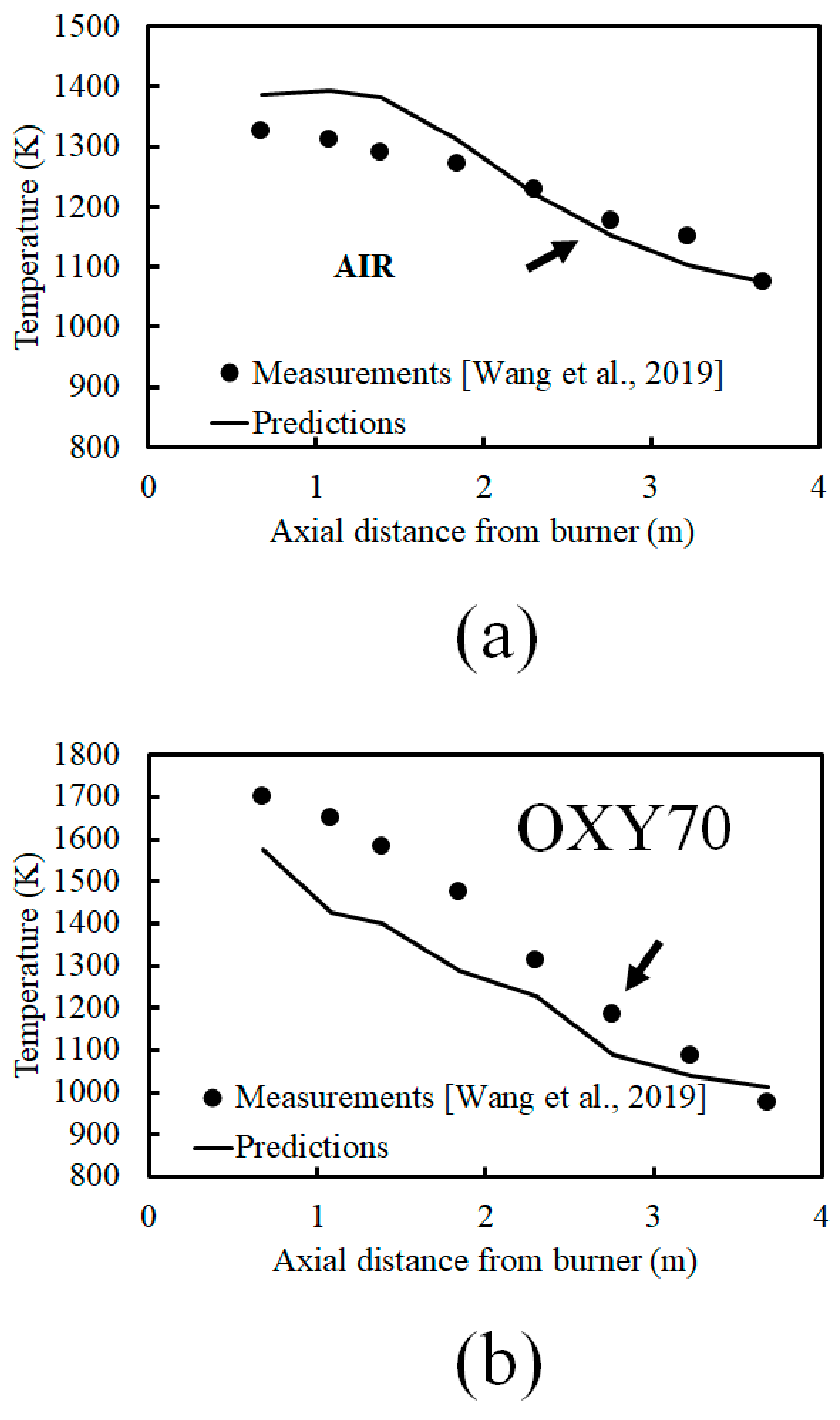
In addition to the fly ash PSD, temperature and velocities are the primary variables in Table 3 influencing the deposition rate predictions. While a highly resolved boundary layer grid enabled us to represent the velocity near the deposit surface accurately, the fidelities in gas temperature were ascertained by comparing the simulation predictions with the experimental measurements. The measured and predicted axial gas temperature profiles in the AIR and OXY70 scenarios with the probe location indicated by an arrow are shown in Figure 3. Good agreement between the prediction and measurements from Wang et al. [12] is shown for both cases, which further indicates the adequacy of the combustion simulations and that of the variables reported in Table 3. The peak flame temperatures occur around Port 2, corresponding to the second data point. In the OXY70 scenarios, the peak gas temperature (1701 K) was much higher than in AIR (1324 K). However, at the vicinity of the deposit probe (Port 6 as indicated by the arrows), the temperatures for both combustion conditions fall within 1250–1300 K as a result of increased heat loss in the OXY70 scenario due to higher temperatures and higher concentrations of radiatively participating gases. In the decoupled deposition rate calculations, adiabatic walls were assumed with the inlet gas temperatures set at values close to the experimental measurements to ensure that the velocity and temperature fields near the deposit surface closely represented the experimental conditions.

2.2. Ash Deposition Rates (without Agglomeration)

The fly ash impaction rates based on the modeled fly ash PSD shown in Figure 2 are reported in Table 4.
While the predicted impaction rates in Table 4 are greater than the measured deposition rates for the Petcoke–AIR combustion scenario, the impaction rates for the Petcoke–OXY70 conditions are significantly lower than the measured deposition rates. This indicates that irrespective of the capture methodology employed, the fly ash PSD for the OXY70 conditions cannot be represented simply based on the shrinking sphere methodology and assuming no fly ash agglomeration as shown in Figure 2. OXY70 conditions are characterized by higher temperatures and longer residence times that promote ash agglomeration and the shifting of the fly ash PSD to coarser (larger) particle sizes as observed with other fuels in this combustor [21].
The predicted deposition rates and percentage capture (computed as the ratio of deposition rate to impaction rate) employing the PKE-critical-viscosity-based capture criterion and different models for μ P are reported in Table 5.
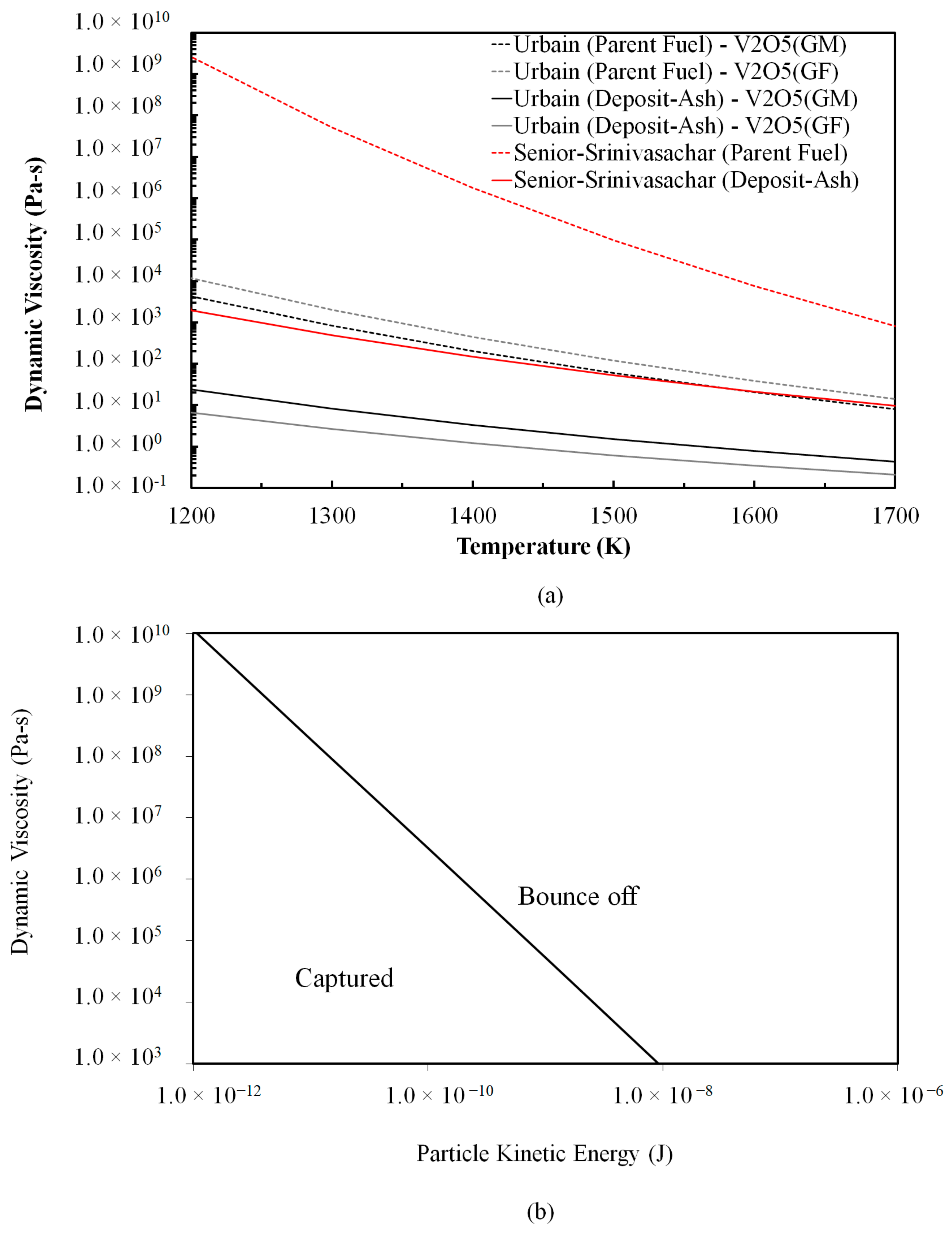
It is interesting to see in Table 5 that despite the wide variations in μ P predictions among the different viscosity models (cf. Figure 4a), most of the models when employed with the PKE–µP (cf. Equations (2) and (3)) predict a 100% capture rate for this temperature range. Furthermore, the deposition rate predictions for the Petcoke-AIR scenario (43 g/m2-h) are seen to agree well with the measured deposition rates (33 g/m2-h). A notable exception is observed for the deposition rate predictions based on the Senior and Srinivasachar µP model [22] where the parent ash compositions were employed to estimate µP, where significantly lower deposition rates were obtained. This is attributed to the significantly higher µP predictions based on the parent fuel ash compositions as shown in Figure 4a. These results indicate that it is important to take into account the Fe transformation and enrichment in the fly ash (and not simply use the ash composition of the parent fuel when attempting to estimate the deposition rates in PC combustion).
While the deposition criteria for ash originating from coal and biomass combustion have been reviewed extensively [15,16], modeling frameworks for PC fly ash deposition is currently lacking. While Table 5 shows that a PKE-critical-viscosity capture criterion (Equations (2) and (3)) may be promising as long as information regarding the fly ash PSD is available near the deposit surface, we also explored a Weber-number-based capture criterion in this study. The Weber number (cf. Equation (12)) represents the ratio of PKE to surface tension. As a simple capture model, a critical Weber number ( W e c r ) is defined, and particles that have a particle We number below W e c r are assumed to be captured. Values of W e c r generally employed in these types of calculations are generally of the order of unity [15,31], indicating a threshold where surface tension effects start to exceed PKE. Table 6 shows the predicted deposition rates when employing different W e c r (0.1 and 1.0) for particle capture. In other words, the impacting particles are captured if their We is less than 0.1 and 1.0, respectively.
First, the sharp increase in the deposition rate predictions between W e c r = 0.1 and W e c r = 1.0 indicates the challenge of employing a single ad hoc W e c r to make predictions. Table 6 indicates that a significant portion (~80%) of the impacting fly ash particles have a particle Weber number in the range of 0.1 < We < 1.0 and 100% of the impacting particles have a We < 1.0. Again, the close agreement between the measured and predicted deposition rates for the Petcoke-AIR scenario shown in Table 5 and Table 6 indicate that the fly ash PSD in this scenario may be modeled based on the shrinking sphere methodology and assuming no agglomeration (cf. Figure 2). Second, at the temperature and velocity conditions associated with this scenario, very likely all of the impacting particles are captured due to the Fe-rich sticky ash.

2.3. Ash Deposition Rates (with Agglomeration in the OXY70 Scenario)

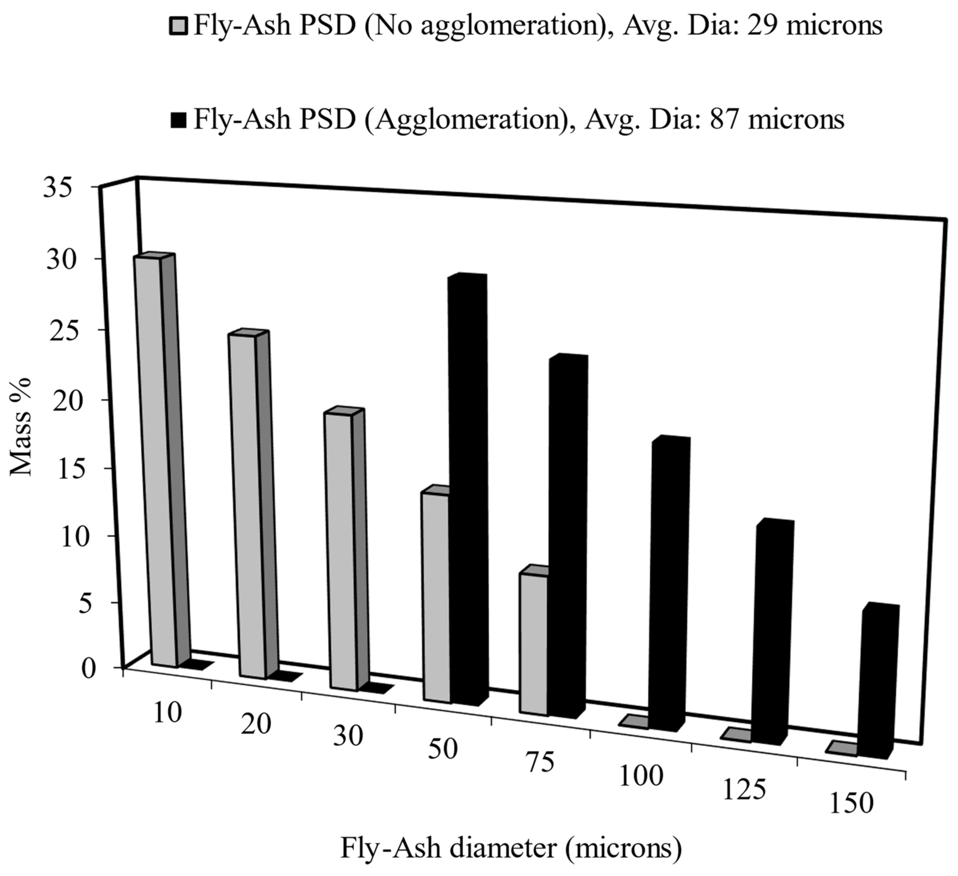
In order to model the agglomeration process resulting from the higher temperatures and longer residence times associated with the OXY70 scenario, the fly ash PSD in Figure 2 was shifted to a coarser particle range in an ad hoc manner to match the measured deposition rates. This was deemed necessary since the fly ash PSD in the size range ( d P > 10 µm) that is of importance to the outer ash deposition rates was not measured or reported in the experiments [12]. Figure 5 reflects the shift in the fly ash PSD to the coarser range under the agglomeration assumption in the OXY70 scenario. A three-fold increase in the mass-weighted average diameter of the fly ash as a result of agglomeration is seen from 29 µm to 87 µm. It is worth pointing out that this increase is in line with the measurements of the fly ash PSD made in AIR and OXY70 combustion scenarios investigated in this combustor for coal fly ash that has been reported in Wu et al. [21]. When the measured fly ash PSD was then fit into a Rosin-Rammler functional form, the average diameter was seen to increase nearly three-fold from 20 µm to 55 µm between the AIR and OXY70 scenarios [19].
The impaction and deposition rate calculations associated with the PC–OXY70 scenario reported in Table 4, Table 5 and Table 6 were repeated with the new fly ash PSD (with agglomeration in Figure 5) and are reported in Table 7, Table 8 and Table 9.
The shift in the fly ash PSD to coarser particles brings the impaction rates for the Petcoke-OXY70 conditions significantly closer to the measured deposition rates.
While coarser particles increase the PKE of the particles, the percentage capture in Table 8 and the insensitivity of the deposition rate predictions to the model for μ P are similar to the trends reported in Table 5 for the Petcoke–AIR scenario. In other words, most of the models when employed with the PKE– μ P (cf. Equations (2) and (3)) predict a 100% capture rate for this temperature range. Furthermore, the deposition rate predictions for the Petcoke–OXY70 scenario (158 g/m2-h) are seen to agree well with the measured deposition rates (156 g/m2-h). A notable exception is observed for the deposition rate predictions based on the Senior and Srinivasachar μ P model [22] where the parent ash compositions were employed to estimate μ P , where significantly lower deposition rates were obtained. Again, this is attributed to the significantly higher μ P predictions based on the parent fuel ash compositions as shown in Figure 4a.
Table 9 shows the predicted deposition rates when employing different W e c r (0.1, 1.0, and 10.0, respectively) for particle capture. In other words, the impacting particles are captured if their We is less than 0.1, 1.0, and 10.0, respectively.
In contrast to the results reported in Table 6 where 100% of the impacting particles were found to have a We < 1.0, Table 9 shows that only 52% of the impacting particles at this coarse PSD have a We < 1.0 and the remaining 48% of the impacting fly ash particles have a particle Weber number in the range of 1.0 < We < 10.0. This is an interesting result considering that while the average particle diameters (cf. Equation (12)) saw a three-fold increase, the particle velocity in the OXY70 scenario generally decreased nearly three-fold in the OXY70 scenario (cf. Table 3 and Table 13), thereby offsetting the effects of the diameter increase. While the surface tension (cf. Equation (11)) also decreases with an increase in temperature in the OXY70 scenario, its effect on the particle We is assumed to be minor. In a similar vein, the PKE in OXY70 scenarios have also been predicted to shift to higher values in comparison to combustion in AIR (despite lower gas velocities) as observed in previous studies [20]. The results in Table 9 therefore highlight that the particle We number distribution cannot be ascertained simply based on the fly ash PSD and average velocity alone using a plug flow assumption and that the flow field near the complex deposit probe geometry needs to be resolved accurately using 3D simulations to more accurately account for size segregation of the different sized fly ash particles that play a role in determining particle impaction [19,32].
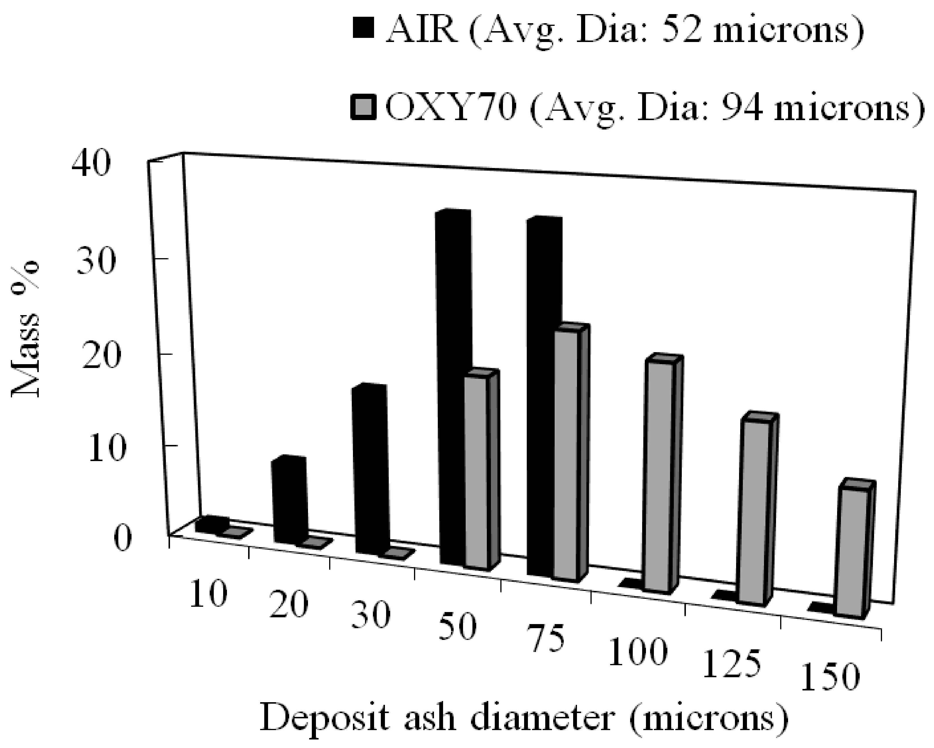
Given that the deposition rates were in reasonable agreement with the experimental measurements in the AIR (cf. Table 5) and OXY70 scenarios (cf. Table 8), the mass percentages of the deposit ash across different sizes are shown in Figure 6 along with the mass-weighted average diameter of the deposits. The value of Figure 6 lies in the fact that in the absence of PSD measurements of the coarse fly ash particles (given that isokinetic sampling of the fly ash at these low velocities, cf. Table 3 can be challenging [33]), the fly ash PSD may be inferred based on the deposit PSD measurements when employed in conjunction with a suitable capture criterion as demonstrated in [32].

2.4. Sensitivity Analyses

The robustness of the PKE-critical-viscosity-based capture criterion in conjunction with fly ash PSD for predicting the deposition rate in Petcoke combustion scenarios was investigated by examining the deposition rate prediction variations as a function of gas temperature and fly ash density, respectively (given their important role in determining µ p and PKE, respectively). The gas temperatures were varied by ± 50   K and ± 100   K , respectively, from their values reported in Table 3 for AIR and OXY70. Table 5 and Table 8 show that the deposition rate predictions when employing the PKE-critical-viscosity-based capture criterion were relatively insensitive to how the role played by V 2 O 5 was being modeled when determining the viscosity (i.e., as a glass formed or glass modifier). In addition, based on the results in Table 6 and Table 9, temperature sensitivities to employing critical Weber numbers ( W e c r ) of 1.0 and 10.0 were explored. Table 10 and Table 11 show the effect of gas temperatures on the predicted ash deposition in the AIR and OXY70 scenarios. The observed insensitivity of the deposition rates to temperature therefore provides credence to the fact that a PKE– μ P -based capture model where the viscosity is computed employing the Urbain et al. [23] formulation may be employed to predict the deposition rates in Petcoke combustion scenarios as long as the fly ash PSD is adequately represented.

3. Materials and Methods

3.1. Simulation of PC Combustion

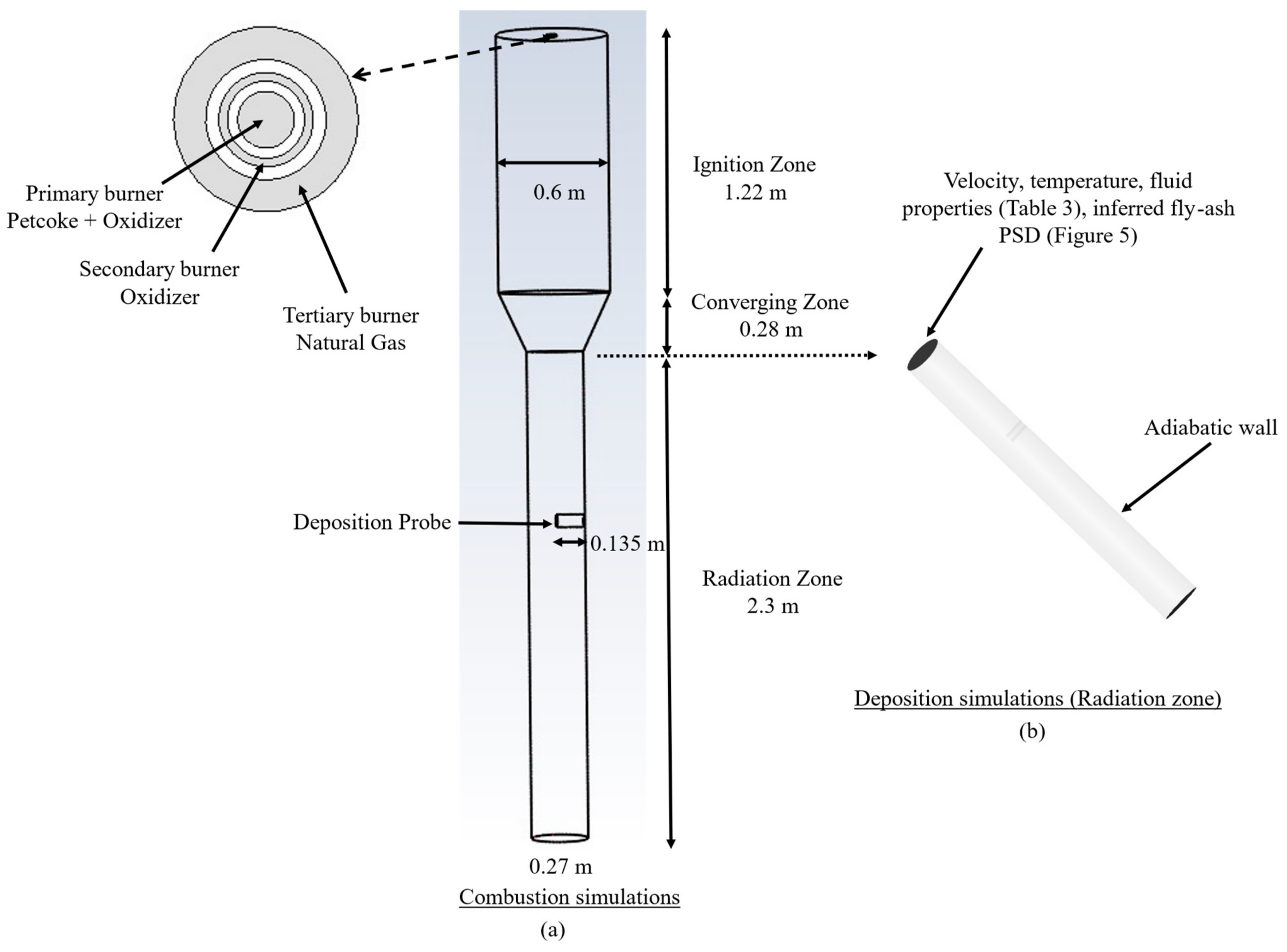
The measurements by Wang et al. [12] were conducted in the downflow laboratory combustor (oxyfuel combustor or OFC) at the University of Utah. The 3D geometrical representation of the combustor is shown in Figure 7a. The geometry was meshed with 1.1 million cells after ensuring the grid convergence of the temperature and velocity fields at this level of refinement. In addition, the boundary layer mesh size criterion recommended by Weber et al. [14] was employed to ensure adequate resolution of the boundary layer near the probe to model particle impaction accurately. The size ( ) of the numerical cells adjacent to the cylindrical probe of diameter D was set within the constraint 0.3240 D / 4 R e . All the simulations were carried out in ANSYS FLUENT v 21 [34]. A two-step mechanism where CO is first produced during devolatilization followed by its oxidation to C O 2 during the second reaction was employed to simulate the homogeneous gaseous combustion reactions. The combustion of solid fuel and the ash deposition simulations were carried out using the Lagrangian Tracking Discrete Phase modeling methodology that accounts for the particle trajectory through various forces, including discrete phase inertia, hydrodynamics, and the force of gravity.
Table 12 provides the properties of PC based on the experimental conditions reported by Wang et al. [12]. Table 13 summarizes the key experimental boundary conditions employed in this study.
The different physics-based models employed to simulate the turbulent combustion process in this study are summarized in Table 14.

3.2. Particle Capture Criterion

3.2.1. PKE-Critical-Viscosity-Based Ash Capture Criterion

Here, the capture probability ( P s t i c k ) was set equal to one if the particle viscosity ( µ P ) is less than or equal to a critical viscosity ( µ P , c r i t i c a l ) :
P s t i c k = 1   i f   µ P µ P , c r i t i c a l
Otherwise P s t i c k is zero. The critical viscosity ( µ P , c r i t i c a l ) was determined based on the particle kinetic energy (PKE) of the impacting particle as [15]:
μ P , c r i t i c a l = 5 × 10 12 P K E 1.78
The capture criterion of Equations (2) and (3) delineating the sticking and bounce-off regions is shown in Figure 4b. Therefore, the PKE and µ p together determine whether the impacting particle is captured or bounces off. Two model formulations were employed to estimate the particle viscosity ( µ P ) .

Senior and Srinivasachar Particle Viscosity Model [22]

The particle viscosity model proposed by Senior and Srinivasachar [22] has been shown to be accurate in the low-fouling region corresponding to the temperature range of 1200–1400 K of interest in this study and has been successfully employed to make deposition rate predictions in biomass [20], lignite [24], and bituminous coals [19]. However, its validity in PC fly ash scenarios has not been explored. A power law expression is used to model the particle viscosity ( μ P ) as a function of temperature as:
μ P = A T p exp 1000 B T p
where T P is the particle temperature, and the constants “A” and “B” are computed based on the composition of the fly ash. First, “B” is calculated from the mass fractions of different metal oxide ( M x O y ) constituents of the ash as:
B = f M x O y
The model constant “A” is a function of the constant B above and NBO/T:
A = f B , N B O T
where NBO/T is the ratio of non-bridging oxygen atoms (NBO) to the tetrahedral oxygen atoms in the glassy silica network of the ash. NBO/T was determined as a function of metal oxide ( M x O y ) compositions. The Senior and Srinivasachar model [22] requires the calculations of the two sets of constants, A and B, corresponding to the high- and low-temperature values for each set of constants, which are then used to compute high and low viscosities correspondingly (cf. Equation (4)). The maximum value of the two at each temperature is then assigned to μ P .

Urbain et al. [23] Particle Viscosity Model

A possible shortcoming of the Senior and Srinivasachar model [22] in the context of PC fly ash is that their model does not account for V 2 O 5 and N i O that may be significantly enriched in the PC fly ash [8]. Therefore, the model proposed by Urbain et al. [23] was employed for comparison, where the individual metal oxides in the fly ash were categorized into three groups: glass formers (g), glass modifiers (m), and amphoterics (a). This grouping step enabled us to include the effect of vanadium oxide and nickel oxide on the particle viscosity. The power law expression for the Urbain et al. [23] particle viscosity model is written as:
μ P = a T P exp 1000 b T P
where T P is the particle temperature. The constant “b” is a function of the constant “ ω ” and the molar fraction of S i O 2 :
b = f ω , x S i O 2
The parameter ω is calculated as:
ω = x m x m + x a
where x m and x a are the total molar fraction of all glass modifiers and all amphoterics, respectively. Since vanadium oxide can act as a glass modifier as well as a glass former depending on its concentration, two separate viscosity relationships were developed following the procedures above. Finally, the constant “a” in Equation (7) is then estimated from “b” based on a function form:
a = f b
In addition, both the parent fuel ash and deposit ash compositions measured and reported in Wang et al. [12] were employed to compute μ P . Since the deposit ash was significantly enriched in Fe in comparison to its content in the parent fuel ash, the increase in sticking propensities resulting from this enrichment could then be assessed by carrying out the simulations using identical viscosity model formulations but different fly ash compositions (i.e., assigning them the measured parent fuel ash compositions or the measured deposit ash compositions). Figure 4b shows PC fly ash viscosity predictions employing different models: Senior and Srinivasachar [22] (Equation (4)) and Urbain et al. [23] (Equation (7)); measured ash compositions (deposit-ash, parent fuel); V 2 O 5 as Glass Former (GF) or Glass Modifier (GM) in the Urbain et al. [23] model across a temperature range from 1200 K to 1700 K.
First, using the deposit ash compositions (which are significantly enriched in Fe and therefore sticky [18]) to predict μ P results in significantly lower μ P values (bold lines) in comparison to the corresponding μ P predictions based on the parent fuel ash compositions. The impact of the ash compositions is more pronounced (up to six orders of magnitude) when employing the Senior and Srinivasachar particle viscosity model [22] in comparison to the Urbain et al. [23] model (approximately three orders of magnitude). The NBO/T values (cf. Equation (6)) computed based on the parent fuel ash and deposit ash compositions and employed in the Senior and Srinivasachar particle viscosity model [22] were significantly different (−0.19 and −0.93, respectively) causing significant differences in their viscosities. Comparing the two viscosity models at a fixed composition, the predictions by using the Senior and Srinivasachar model [22] are generally much higher than the corresponding predictions by using the Urbain et al. [23] model. Regarding the use of V 2 O 5 in the silica network, either as a glass former (GF) or a glass modifier (GF) in conjunction with the Urbain et al. [23] model, we find that the viscosity predictions in the temperature range of interest differ by less than an order of magnitude. In conclusion, Figure 4b suggests that both fly ash composition and the viscosity model can potentially impact particle capture significantly with higher capture/deposition rates anticipated when the composition of the impacting fly ash is based on the deposit ash composition, and the Urbain et al. [23] model is employed to model μ P .

3.2.2. Weber-Number-Based Ash Capture Criterion

While the PKE-critical-viscosity-based capture criterion has generally been employed with coal and biomass ashes [15,19,20,24], its validity in modeling PC ash deposition rates has not been established. In addition, due to the widespread variation in μ P employing different viscosity models as shown in Figure 4a, a second Weber-number-based capture criterion was also explored in this study. First, the surface tension ( σ ) of the fly ash was calculated based on its composition as [38]:
σ = 1 i σ i x i 0.15 × T p 1733 × 0.001
where σ i is the particle molar surface tension of ash constituents provided by Mills and Rhines [38] and x i is the molar fraction of the ash component. The particle Weber number of the impacting particle was then calculated as:
W e = ρ P d P u P 2 σ
where ρ P , d P , and u P represent the particle density, particle diameter, and particle velocity, respectively. Three separate sets of Weber-number-based criteria, namely We < 0.1, 1.0, and 10, were employed for both AIR and OXY70. The particle was captured and removed with no further Lagrangian tracking calculation when the assigned We criterion was met. Since the focus of this paper was on obtaining a mechanistic understanding of the deposition rates during PC combustion through an investigation of different capture methodologies, the fly ash PSD in the size range of 10 μ m < d P < 150 μ m was modeled as 8 discrete diameter bins to closely represent the “predicted” fly ash distribution based on the shrinking sphere methodology. The diameters and mass fractions assigned to each bin are shown as dots in Figure 2.

4. Conclusions

Co-firing petroleum coke (PC) with natural gas in oxygen-enriched atmospheres (up to 70 mol % in oxidizer), representative of second-generation, atmospheric pressure oxy-combustion units, presents a promising option for energy production. The high temperatures resulting during this process may help alleviate the low volatility and flammability, as well as loss of ignition shortcomings that have plagued its utilization as a standalone fuel. However, this transition is currently hindered by our lack of understanding of the factors influencing the slagging propensity of PC fly ash. To fill this void, a Computational Fluid Dynamic (CFD) study was carried out to match the measured outer ash deposition rates associated with the combustion of PC in AIR and O 2 / C O 2 (70/30 vol%, OXY70) atmospheres. Since fly ash PSD near the deposit surface (that is crucial for estimating the deposition rates) was not measured, it was estimated from the parent fuel PSD and its ash content assuming a “shrinking sphere” assumption and a final ash density of 2500 kg/ m 3 . This was hypothesized based on the high fixed carbon content and non-porous nature of the parent fuel. This estimated fly ash PSD was employed in conjunction with particle kinetic energy (PKE), particle viscosity ( µ P ) (PKE– μ P ), and a Weber-number-based capture criterion to predict the inertial ash deposition rates. Based on the results, the following conclusion can be drawn:
  • The predicted gas temperatures near the deposit probe were in reasonable agreement with the measurements for both combustion conditions. In addition, the velocity field surrounding the probe was adequately resolved using a fine boundary layer mesh as per the criterion recommended for predicting particle impaction accurately [14]. Simulations showed complete carbon burnout before reaching the probe, concurring with carbon-free deposits obtained from the experiments. Therefore, the adequacy of the combustion models employed in the simulations was established.
  • In order to assess the robustness of our predictions and conclusions regarding the use of the PKE– μ P capture criterion, deposition rate prediction sensitivities to the particle viscosity ( µ P ) model were assessed using two commonly used model formulations: the Senior and Srinivasachar [22] and the Urbain et al. [23] models. In addition, both parent fuel ash composition and the deposit ash compositions were employed to estimate µ P in view of the fact that the ash deposits in the experiments were found to be significantly enriched in Fe (which may promote stickiness). The deposition rate predictions were close to the measurements and were insensitive to the µ P model formulation employed as long as the deposit ash composition was employed in the µP calculations (to account for the Fe enrichment). µ P based on the Senior and Srinivasachar [22] model which has previously been found to be accurate in modeling the deposition rates from coal and biomass fly ash in this temperature range (1200 K–1400 K) [19,20,24] underestimated the deposition rates. This likely points to the fact that the fly ash composition for determining µ P is a more important factor for deposition rate prediction than the exact model formulation for µ P .
  • Since PC ash is also characterized by high concentrations of V 2 O 5 , which may either play the role of a glass former (GF) or a glass modifier (GM), particle viscosities ( µ P ) were also individually estimated using V 2 O 5 as a GF or GM when employed to estimate the parameters in the Urbain et al. [23] model. In regard to the temperature range of interest in this study, the µ P predictions differed by less than an order of magnitude depending on whether V 2 O 5 was employed as a GF or GM and did not impact the deposition rate predictions.
  • Employing a critical Weber number ( W e c r ) of unity as a capture criterion also resulted in deposition rate predictions close to the measurements for the PC–AIR combustion scenario. However, a critical Weber number ( W e c r ) of 10.0 with a modified fly ash PSD was necessary to match the measurements for the PC–OXY70 scenario. Therefore, we caution against using such a simplistic ad hoc W e c r criterion to match deposition rates in one scenario and extend it to other scenarios since they cannot be universally and generally applied in this manner. For instance, ~80% of the impacting fly ash particles in the PC AIR scenario had a particle Weber number in the range of 0.1 < We < 1.0 which meant that a five-fold variation in deposition rate prediction is associated with the narrow range of 0.1 < W e c r < 1.0.
  • The impaction rates in the PC-OXY70 scenario were significantly lower than the measured deposition rates. This necessitated an ad hoc modification of the fly ash PSD to a coarser range that may be attributed to agglomeration resulting from a longer residence time and higher temperatures. The mass-weighted diameter increase in the fly ash PSD in the OXY70 scenario (which was deemed necessary to match the measured deposit rates) was found to be in line with the measured PSD shifts between AIR and OXY70 fly ash observed in previous studies within this combustor [21].
  • Our deposition rate predictions were relatively insensitive to ± 50   K and ± 100   K temperature variations in the PC-AIR and PC-OXY70 scenarios, respectively, thereby establishing the robustness of our inferred PSD as well as the PKE– μ P capture criterion.
  • The capture rates were close to 100% across the investigated scenarios resulting from the sticky Fe-rich fly ash. Such high capture rates (>50%) are in line with previous studies [19,20,32,33,39]. The study therefore highlights the importance of resolving the impaction rates accurately through well-resolved fly ash PSD and velocity fields. For the range of velocities encountered in this study (0.4 m/s–1.0 m/s), the fly ash PSD in the size range of 10 µm to 150 µm needs to be resolved accurately. Naturally, the fly ash PSD size range of importance may shift to finer size fractions at higher gas velocities [24,39].

Author Contributions

Conceptualization, G.K.; methodology, N.D.T.N.; software, G.K.; validation, N.D.T.N.; formal analysis, N.D.T.N.; investigation, N.D.T.N.; resources, G.K.; data curation, N.D.T.N.; writing—original draft preparation, N.D.T.N.; writing—review and editing, G.K.; visualization, N.D.T.N.; supervision, G.K.; project administration, G.K. All authors have read and agreed to the published version of the manuscript.

Funding

This research received no external funding.

Data Availability Statement

Data are available upon request.

Conflicts of Interest

The authors declare no conflicts of interest.

Nomenclature

dDiameter, m
PKEParticle kinetic energy, J
ReReynolds number
StkStokes Number
TTemperature, K
uVelocity, m/s
WeWeber number
xMolar fraction
Greek Symbols
ΔBoundary layer cell height, m
γSurface tension, N/m
ηEfficiency
ρDensity, kg/m3
µViscosity, kg/m-s
Subscripts
crDenotes critical
gDenotes gas
PDenotes particle

References

  1. Bryers, R.W. Utilization of petroleum coke and petroleum coke/coal blends as a means of steam raising. Fuel Process. Technol. 1995, 44, 121–141. [Google Scholar] [CrossRef]
  2. Pisa, G.D.; Bondi, G. SNOX™ Flue Gas Treatment Technology for Boilers Burning Petcoke, Giandomenico Bondi-Raffineria di Gela, Rio De Janeiro, 28–30 May 2008.
  3. Pak, D.F.; Kucherov, V.V.; Shabanov, I.I.; Epikhin, A.N.; Treskov, I.V.; Kudryavtsev, S.A. Innovative Technologies in the Repowering of the Nizhnekamsk CHPP by Upgrading the TGME-464 Boiler to Combust Pulverized Petroleum Coke. Power Technol. Eng. 2019, 52, 714–719. [Google Scholar] [CrossRef]
  4. Hirayama, Y.A.; Hishida, M.A.; Yamamoto, Y.O.; Makiura, S.; Arakawa, Y.; Okamoto, A. Operation results of power station with petroleum coke firing boiler. Mitsubishi Heavy Ind. Tech. Rev. 2007, 44, 1–7. [Google Scholar]
  5. Wang, J.; Anthony, E.J.; Abanades, J.C. Clean and efficient use of petroleum coke for combustion and power generation. Fuel 2004, 83, 1341–1348. [Google Scholar] [CrossRef]
  6. Pearce, R.; Grusha, J. Reliant Energy Tangential Low NOx System at Limestone Unit 2 Cuts Texas Lignite, PRB, and Pet Coke NOx. 2001. Available online: https://www.lexissecuritiesmosaic.com/gateway/FedReg/files_tp_firsys_01_02.pdf (accessed on 12 January 2024).
  7. Conn, R.E.; Shan, J.; Vatsky, J. Low NOx Combustion Systems for Minimizing NOx and Fly Ash LOI: Wall-Firing Petcoke and T-Firing Severe Slagging Coal; Advanced Burner Technologies Corporation: Kennesaw, GA, USA, 2003. [Google Scholar]
  8. Hower, J.C.; Thomas, G.A.; Mardon, S.M.; Trimble, A.S. Impact of co-combustion of petroleum coke and coal on fly ash quality: Case study of a western Kentucky power plant. Appl. Geochem. 2005, 20, 1309–1319. [Google Scholar] [CrossRef]
  9. Cain-Borgman, C. Petroleum coke refueling of underutilized oil-fired assets produces low cost power. In Proceedings of the Power-Gen Conference, Las Vegas, NV, USA, 6 December 2005. [Google Scholar]
  10. Fan, Y.; Si, P. The Study of Numerical Simulation of Oxygen enriched Burner System. CFD Lett. 2010, 2, 197–207. [Google Scholar]
  11. Yuzbasi, N.S.; Selcuk, N. Pyrolysis and combustion behavior of ternary fuel blends in air and oxy-fuel conditions by using TGA-FTIR. Combust. Sci. Technol. 2012, 184, 1152–1163. [Google Scholar] [CrossRef]
  12. Wang, Y.; Wu, J.; Li, X.; Yu, D.; Xu, M.; Wendt, J.O.L. Ash aerosol partitioning and ash deposition during the combustion of petroleum coke/natural gas mixtures. Fuel 2019, 256, 115982. [Google Scholar] [CrossRef]
  13. Wang, Y.; Li, X.; Wendt, J.O.L. On ash deposition rates from air and oxy-combustion of pulverized coal, petroleum coke, and biomass. Energy Fuels 2019, 33, 5849–5858. [Google Scholar] [CrossRef]
  14. Weber, R.; Schaffel-Mancini, N.; Mancini, M.; Kupka, T. Fly ash deposition modelling: Requirements for accurate predictions of particle impaction on tubes using RANS-based computational fluid dynamics. Fuel 2013, 108, 586–596. [Google Scholar] [CrossRef]
  15. Kleinhans, U.; Wieland, C.; Frandsen, F.J.; Spliethoff, H. Ash formation and deposition in coal and biomass fired combustion systems: Progress and challenges in the field of ash particle sticking and rebound behavior. Prog. Energy Combust. Sci. 2018, 68, 65–168. [Google Scholar] [CrossRef]
  16. Cai, Y.; Tay, K.; Zheng, Z.; Yang, W.; Wang, H.; Zeng, G.; Li, Z.; Boon, S.K.; Subbaiah, P. Modeling of ash formation and deposition processes in coal and biomass fired boilers: A comprehensive review. Appl. Energy 2018, 230, 1447–1544. [Google Scholar] [CrossRef]
  17. Fakourian, S.; McAllister, Z.; Fry, A.; Wang, Y.; Li, X.; Wendt, J.O.; Dai, J. Modeling ash deposit growth rates for a wide range of solid fuels in a 100 kW combustor. Fuel Process. Technol. 2021, 217, 106777. [Google Scholar] [CrossRef]
  18. Bool, L.E., III; Peterson, T.W.; Wendt, J.O. The partitioning of iron during the combustion of pulverized coal. Combust. Flame. 1995, 100, 262–270. [Google Scholar] [CrossRef]
  19. Krishnamoorthy, G. Aerodynamic influences on the outer ash deposition rates during oxy-coal combustion. Clean. Chem. Eng. 2022, 3, 100057. [Google Scholar] [CrossRef]
  20. Krishnamoorthy, G. Modeling Ash Deposition and Shedding during Oxy-Combustion of Coal/Rice Husk Blends at 70% Inlet O2. Int. J. Coal Sci. Technol. 2023, 10, 27. [Google Scholar] [CrossRef]
  21. Wu, J.; Wang, Y.; Han, J.; Li, X.; Yu, D.; Xu, M.; Wendt, J.O. Ash Formation and Deposition in Oxy-fuel Combustion of Rice Husk, Coal, and Their Blend with 70% Inlet O2. Energy Fuels 2019, 34, 890–899. [Google Scholar] [CrossRef]
  22. Senior, C.L.; Srinivasachar, S. Viscosity of ash particles in combustion systems for prediction of particle sticking. Energy Fuels 1995, 9, 277–283. [Google Scholar] [CrossRef]
  23. Urbain, G.; Bottinga, Y.; Richet, P. Viscosity of liquid silica, silicates and alumino-silicates. Geochim. Cosmochim. Acta 1982, 46, 1061–1072. [Google Scholar] [CrossRef]
  24. Krishnamoorthy, G.; Bloom, E.; Viswanathan, K.; Patwardhan, S.S.; Stadem, D.J.; Benson, S. Measurements and Prediction of Ash Deposition in a Cyclone-Fired Boiler Operating under Variable Load Conditions. Fluids 2023, 8, 305. [Google Scholar] [CrossRef]
  25. Vargas, S.; Frandsen, F.J.; Dam-Johansen, K. Rheological properties of high-temperature melts of coal ashes and other silicates. Prog. Energy Combust. Sci. 2001, 27, 237–429. [Google Scholar] [CrossRef]
  26. Doweidar, H.; Megahed, A.; Gohar, I.A. Mixed ionic-electronic conduction in sodium borate glasses with low V2O5 content. J. Phys. D Appl. Phys. 1986, 19, 1939. [Google Scholar] [CrossRef]
  27. D’Souza, S.A.; Banik, S.; Vuthaluru, H.B.; Pisupati, S.V. Comparison of Natural and Synthetic Petroleum Coke Slag Viscosities under Reducing Conditions: Applicability of Predictive Models Using Factsage and Modified Urbain Model. Fuels 2021, 2, 37–47. [Google Scholar] [CrossRef]
  28. Alekhnovich, A.N.; Bogomolov, V.V.; Artem’eva, N.V. Petroleum coke characteristics and use in power industry. Power Technol. Eng. 2019, 53, 339–343. [Google Scholar] [CrossRef]
  29. Chen, J.; Lu, X. Progress of petroleum coke combusting in circulating fluidized bed boilers—A review and future perspectives. Resour. Conserv. Recycl. 2007, 49, 203–216. [Google Scholar] [CrossRef]
  30. Góral, D.; Wylenżek, A. The efficient coal alternative. Petroleum coke-fired CFB boilers in Europe. In Proceedings of the Coal Gen Europe, Warsaw, Poland, 14–16 February 2012. [Google Scholar]
  31. Yong, S.Z. Multiphase Models of Slag Layer Built-Up in Solid Fuel Gasification and Combustion. Ph.D. Thesis, Massachusetts Institute of Technology, Cambridge, MA, USA, 2010. [Google Scholar]
  32. Krishnamoorthy, G.; Nguyen, N.D.T. Modeling outer ash deposition rates in second generation atmospheric pressure oxy-fuel combustion systems. Combust. Sci. Technol. 2023, 195, 3440–3455. [Google Scholar] [CrossRef]
  33. Beckmann, A.M.; Mancini, M.; Weber, R.; Seebold, S.; Müller, M. Measurements and CFD modeling of a pulverized coal flame with emphasis on ash deposition. Fuel 2016, 167, 168–179. [Google Scholar] [CrossRef]
  34. ANSYS, Inc. ANSYS Fluent Theory Guide; Release 21.1, Online Manual Resource; ANSYS, Inc.: Canonsburg, PA, USA, 2021. [Google Scholar]
  35. Krishnamoorthy, G.; Wolf, C. Assessing the Role of Particles in Radiative Heat Transfer during Oxy-Combustion of Coal and Biomass Blends. J. Combust. 2015, 2015, 793683. [Google Scholar] [CrossRef]
  36. Krishnamoorthy, G. A new weighted-sum-of-gray-gases model for oxy-combustion scenarios. Int. J. Energy Res. 2013, 14, 1752–1763. [Google Scholar] [CrossRef]
  37. Krishnamoorthy, G.; Kuznia, M.E.; Smith, K.M.; Seames, W.S.; Wang, Y.; Wendt, J.O. Aerodynamic effects on outer ash deposition rates in second generation atmospheric pressure oxy-coal combustion systems. Fuel 2021, 303, 121217. [Google Scholar] [CrossRef]
  38. Mills Kenneth, K.; Rhine, J.M. The measurement and estimation of the physical properties of slags formed during coal gasification: 1. Properties relevant to fluid flow. Fuel 1989, 68, 193–200. [Google Scholar] [CrossRef]
  39. Yang, X.; Szuhánszki, J.; Tian, Y.; Ingham, D.; Ma, L.; Pourkashanian, M. Understanding the effects of oxyfuel combustion and furnace scale on biomass ash deposition. Fuel 2019, 247, 36–46. [Google Scholar] [CrossRef]
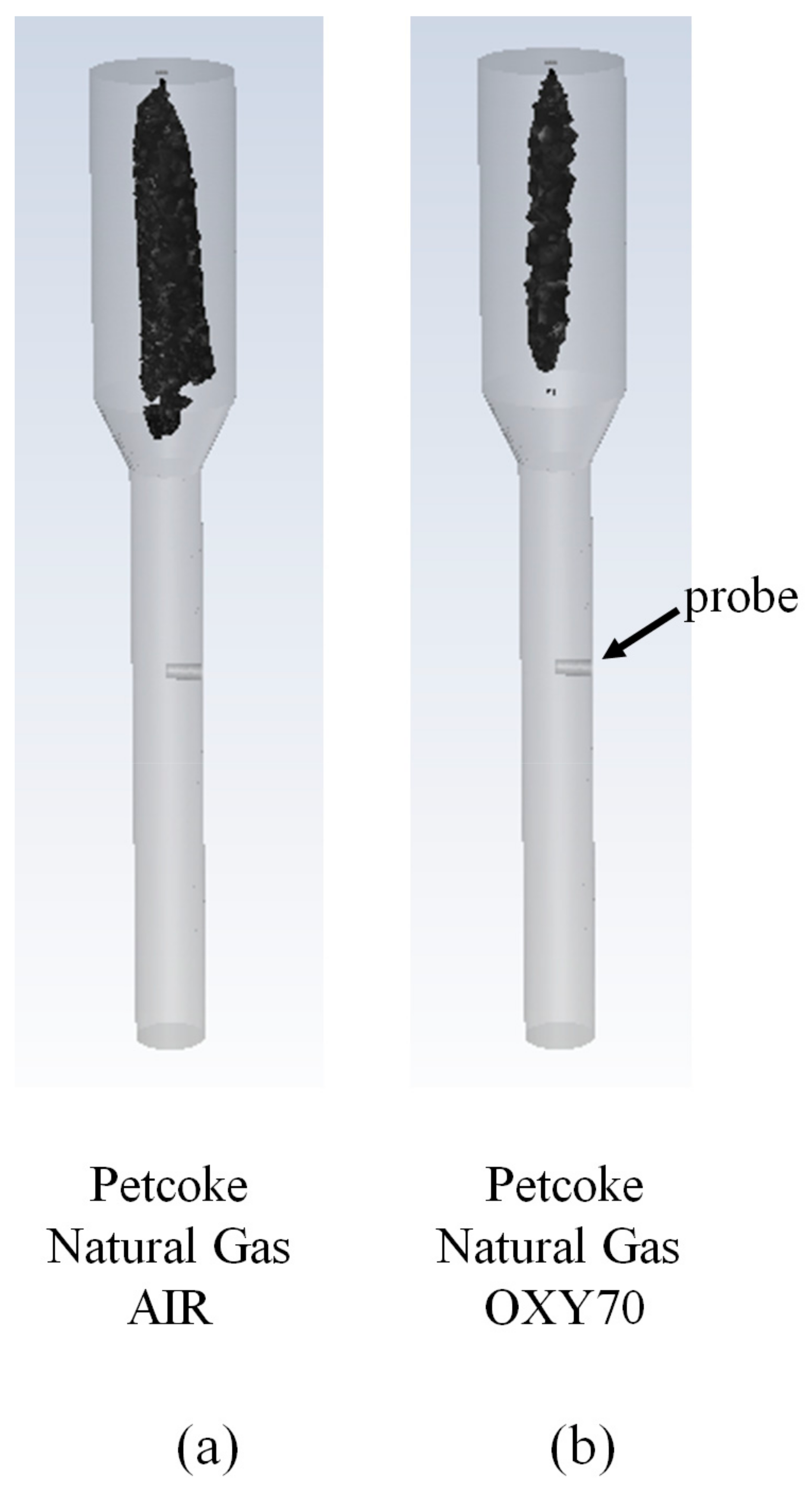
Figure 1. Regions of carbon burnout. (a) PC-AIR; (b) PC-OXY70. The ignition zone (wide section) shows complete carbon burnout before reaching the probe (indicated by arrow).
Methane 03 00005 g001
Figure 2. The measured parent fuel PSD [12] (on secondary axis: upward facing arrow from the bold line) and the modeled fly ash PSD (primary axis: downward facing arrow from the dots and dotted line) using the shrinking sphere methodology assuming no agglomeration.
Methane 03 00005 g002
Figure 3. Centerline temperature profiles along the axial length of the combustion (probe location is indicated by arrow): (a) AIR; (b) OXY70 [12].
Methane 03 00005 g003
Figure 4. (a) PC fly ash viscosity predictions employing different models: Senior and Srinivasachar [22] (Equation (4)) and Urbain et al. [23] (Equation (7)); measured ash compositions (deposit ash, parent fuel); V 2 O 5 as glass former (GF) or glass modifier (GM) in the Urbain et al. [23] model; (b) The particle capture criterion (Equations (2) and (3)) represented as a function of particle viscosity ( µ P ) and particle kinetic energy (PKE).
Methane 03 00005 g004
Figure 5. The modeled fly ash PSD using the shrinking sphere methodology and no agglomeration (associated with PC–AIR) and agglomeration (associated with PC–OXY70).
Methane 03 00005 g005
Figure 6. Deposit particle size distribution when the deposition rates are matched with the experimental measurements: no agglomeration in fly ash (AIR) and agglomeration in fly ash (OXY70).
Methane 03 00005 g006
Figure 7. Geometrical details of the downflow OFC combustor. (a) Domain for combustion simulations; (b) Domain (radiation zone only) for the ash deposition simulations.
Methane 03 00005 g007
Table 1. A summary of previous studies assessing the co-combustion characteristics of petroleum coke with coal on a commercial scale.
ReferencesSummary
R. Pearce and J. Grusha [6]PC co-firing with lignite and Powder River Basin coal (PRB) were evaluated in an 820 MW lignite-fired unit. Effective mixing/blending of PC with other fuels in pulverizers can be challenging. NOx emissions increased with PC in fuel, but the emission might be reduced through selective staging of the combustion air. Lower ash content in PC improved furnace surface cleanliness but resulted in lower firing zone temperatures and steam temperatures.
R.E. Conn et al. [7]Fly ash loss of ignition (LOI) and NOx emissions were assessed in two 660 MW opposed-fired units that fired PC, Colombian coal, and their blends. Fly ash LOI ranged from 18 to 25% when the fuels were co-fired in the same burner/mills. However, LOI reduced to 12 to 15% when PC and coal were fired in separate burners. PC was identified as a difficult fuel to ignite but not so hard to burnout when finely ground.
J.C. Hower et al. [8]The fly ash resulting from the co-combustion of a high Sulfur Illinois Basin coal and PC in a 444-MW power station were collected from an electrostatic precipitator array. Unburned PC accounted for a large fraction of coarse particles (>25 µm). In contrast, V and Ni in the fly ash were mostly found in the finer fly ash size fractions (<25 µm) suggesting their mobility during the combustion process.
Table 2. A summary of previous studies assessing the combustion characteristics of PC under oxygen-enriched conditions.
ReferencesSummary
C. Cain-Borgman [9]A proprietary oxygen-based combustion technology that enabled the retrofit and conversion of existing oil-fired utility boilers to allow the use of 100% petroleum coke as fuel was explored. This involved the selective use of oxygen to stably and efficiently burn PC with a reduced combustion residence time. The enabling technology also allowed the retention of most, if not all, of the original furnace steaming capacity. Additionally, the amount of N O x produced in the furnace was reduced.
Fan and Si [10]The ignition point, burnout temperature and burnout time significantly reduced in oxygen-enriched oxidizer atmospheres (33%) across PC particles of difference sizes.
N. Yuzbasi and N. Selcuk [11]Co-firing of PC with medium volatile bituminous coal and indigenous lignite was carried out in fluidized bed combustion (FBC) in O 2 / N 2 and O 2 / C O 2 mixtures with oxygen concentrations ranging from 21% to 30%. Higher oxygen concentrations resulted in higher weight loss rates, lower ignition temperature, lower burnout temperature, and lower peak temperature.
Y. Wang et al. [12,13]A total of 11 different fuels including PC were combusted in AIR and OXY70 (70 vol % O2 in the oxidizer stream) in a 100 kW entrained combustor to measure their ash deposition rates using a wall-temperature-controlled probe. While the outer deposition rates of PC were in general lower than that of coal due to the lower ash content, the OXY70 conditions resulted in significantly enhanced deposition rates (~4.7 times) in contrast to combustion in AIR.
Table 3. Key boundary conditions associated with the deposition rate calculations.
UnitsAIROXY70
Solid fuel ratekg/s3.778 × 10−4
Ash %%2.99
Ash flow ratekg/s1.13 × 10−5
Ash particle densitykg/m325002500
Flue gas densitykg/m30.30.3
Flue gas viscosityPa-s1.6 × 10−51.4 × 10⁻⁵
Flue gas velocitym/s1.00.4
Flue gas temperatureK12501400
Table 4. Impaction rates (g/m2-h) when modeling the fly ash PSD based on the shrinking sphere methodology and assuming no agglomeration (cf. Figure 2).
Units:
g/m2-h
Measured Deposition Rates [12]Predicted Impaction Rates
(Fly Ash PSD–No Agglomeration)
Petcoke
AIR
3343
Petcoke
OXY70
15648
Table 5. Deposition rates (g/m2-h) employing the PKE-critical-viscosity capture criterion (Equations (2) and (3)) when modeling the fly ash PSD based on the shrinking sphere methodology and assuming no agglomeration (cf. Figure 2).
Units:
g/m2-h
Measured Deposition Rates [12]Predicted Deposition Rates
[Fly Ash PSD–No Agglomeration]
(Percentage Capture)
Viscosity Model
[Composition]
Urbain
(V2O5–Glass Former)
[Parent Fuel]
Urbain
(V2O5–Glass Former)
[Fly Ash]
Urbain
(V2O5–Glass Modifier)
[Parent Fuel]
Urbain
(V2O5–Glass Modifier)
[Fly Ash]
Senior and
Srinivasachar
[Parent Fuel]
Senior and
Srinivasachar
[Fly Ash]
Petcoke
AIR
3343
(100)
43
(100)
43
(100)
43
(100)
4
(9)
43
(100)
Petcoke
OXY70
15648
(100)
48
(100)
48
(100)
48
(100)
9
(19)
48
(100)
Table 6. Deposition rates (g/m2-h) employing a critical Weber ( W e c r )-number-based capture criterion when modeling the fly ash PSD based on the shrinking sphere methodology and assuming no agglomeration (cf. Figure 2).
Units:
g/m2-h
Measured Deposition Rates [12]Predicted Deposition Rates
[Fly Ash PSD–No Agglomeration]
(Percentage Capture)
Deposition Criterion W e c r = 0.1 W e c r = 1.0
Petcoke
AIR
339
(21)
43
(100)
Petcoke
OXY70
15610
(20)
48
(100)
Table 7. Impaction rates (g/m2-h) when modeling the fly ash PSD assuming agglomeration (cf. Figure 5).
Units:
g/m2-h
Measured Deposition Rates [12]Predicted Impaction Rates
(Fly Ash PSD–Agglomeration)
Petcoke
OXY70
156158
Table 8. Deposition rates (g/m2-h) employing the PKE-critical-viscosity capture criterion (Equations (2) and (3)) when modeling the fly ash PSD assuming agglomeration (cf. Figure 5).
Units:
g/m2-h
Measured Deposition Rates [12]Predicted Deposition Rates
[Fly Ash PSD–Agglomeration]
(Percentage Capture)
Viscosity Model
[Composition]
Urbain
(V2O5–Glass Former)
[Parent Fuel]
Urbain
(V2O5–Glass Former)
[Fly Ash]
Urbain
(V2O5–Glass Modifier)
[Parent Fuel]
Urbain
(V2O5–Glass Modifier)
[Fly Ash]
Senior and
Srinivasachar
[Parent Fuel]
Senior and
Srinivasachar
[Fly Ash]
Petcoke
OXY70
156158
(100)
158
(100)
158
(100)
158
(100)
0
(0)
158
(100)
Table 9. Deposition rates (g/m2-h) employing a critical Weber (Wecr)-number-based capture criterion when modeling the fly ash PSD assuming agglomeration (cf. Figure 5).
Units:
g/m2-h
Measured Deposition Rates [12]Predicted Deposition Rates
(Fly Ash PSD–Agglomeration)
(Percentage Capture)
Deposition Criterion Wecr = 0.1Wecr = 1.0Wecr = 10.0
Petcoke
OXY70
1566
(4)
82
(52)
158
(100)
Table 10. Sensitivity of the deposition rates (g/m2-h) to gas temperature in Petcoke–AIR.
Petcoke–AIR (Fly Ash PSD–No Agglomeration)
Measured Deposition Rate: 33 g/m2-h
Deposition Criterion Wecr = 1.0Urbain
(V2O5–Glass Modifier)
[Fly Ash]
Gas temperature (K)120012501300120012501300
Predicted deposition rate (g/m2-h)434343434343
Table 11. Sensitivity of the deposition rates (g/m2-h) to gas temperature in Petcoke–OXY70.
Petcoke–OXY70 (Fly Ash PSD–Agglomeration)
Measured Deposition Rate: 156 g/m2-h
Deposition CriterionWecr = 10.0Urbain
(V2O5–Glass Modifier)
[Fly Ash]
Gas temperature (K)130013501400130014001500
Predicted deposition rate (g/m2-h)158158159158158159
Table 12. Characteristics of the petroleum coke (PC) employed in this study.
Proximate Analysis (wt. %)Ultimate Analysis
(wt. %, Dry Ash Free)
Petroleum cokeFixed Carbon86.26C82.51
Volatiles10.18H6.02
Ash2.99N1.71
Moisture0.57S5.65
HHV (kJ/kg)34.4O0.49
Table 13. Key boundary conditions employed in this study as per the experiments of Wang et al. [12].
Petcoke
AIR
Petcoke
OXY70
Petcoke mass flow rate (kg/h)1.361.36
Natural gas mass flow rate (kg/h) (Tertiary burner)1.361.36
Primary burner oxidizer mass flow rate (kg/h)10.810.8
Primary burner species concentrations (mol %)
O22121
N2790
CO2079
Secondary burner oxidizer mass flow rate (kg/h)30.67.2
Secondary burner species concentrations (mol %)
O221100
N2790
CO200
Table 14. A summary of the important physics-based models employed in this study.
Physics Being ModeledModeling Option
Particle devolatilization (heterogeneous)Constant rate (50, 1/s)
Char oxidation (heterogeneous)Shrinking sphere * (density fixed at 2500 kg/m3 and PSD varies depending on mass consumption)
Volatile combustion (homogeneous) (2-step reaction)
Step 1: C0.35H18.7O0.09N0.3824 + 4.80 O2 → 0.35 CO + 9.35 H2O + 0.1912 N2
Step 2: CO + 0.5 O2 → CO2
Finite rate/Eddy dissipation
TurbulenceRealizable k-epsilon
Particle Drag lawMorsi-Alexander
Model describing radiative transportDiscrete Ordinates
Particle radiative propertyParticle-burnout-dependent absorption (Qabs)
and scattering efficiencies (Qscat) [35] *
Particle scattering phase functionAnisotropic (forward scattering)
Gas-phase radiative propertynon-gray weighted sum of gray gases [36] *
Ash capture/DepositionParticle Kinetic Energy-critical-viscosity-based criterion [19] *, Weber-number-based capture criterion [37] *
* These models were implemented as user-defined functions or add-on modules.
Disclaimer/Publisher’s Note: The statements, opinions and data contained in all publications are solely those of the individual author(s) and contributor(s) and not of MDPI and/or the editor(s). MDPI and/or the editor(s) disclaim responsibility for any injury to people or property resulting from any ideas, methods, instructions or products referred to in the content.