Tutorial

Dependability Modeling of Software Systems with UML and DAM: A Guide for Real-Time Practitioners

by
Simona Bernardi
1,†,
José Merseguer
1,*,† and
Dorina C. Petriu
2,†
1
Departamento de Informática e Ingeniería de Sistemas, Universidad de Zaragoza, 50018 Zaragoza, Spain
2
Department of Systems and Computer Engineering, Carleton University, Ottawa, ON K1S 5B6, Canada
*
Author to whom correspondence should be addressed.
These authors contributed equally to this work.
Software 2022, 1(2), 146-163; https://doi.org/10.3390/software1020007
Submission received: 28 December 2021 / Revised: 17 January 2022 / Accepted: 22 March 2022 / Published: 2 April 2022

Abstract

:
The modeling of system non-functional properties is a broad field. Among these properties, dependability is an important one for real-time and embedded systems. On the other hand, UML offers the profiling mechanism to address specific modeling domains. In particular, the DAM (dependability analysis and modeling) profile provides a modeling framework for dependability in the model-driven paradigm. This work is for practitioners to understand the basics of dependability modeling, using DAM. In this sense, the paper digests the literature to understand the concept of the UML profile, the MARTE profile and to obtain a practical guide on dependability modeling using DAM. The modeling approach is illustrated through a case study taken from the literature.

1. Introduction

Software development has been recognized, for decades, as one of the most challenging engineering activities [1]. This is why software modeling has gained importance as a discipline that offers languages, methods and methodologies to address the complexity of software development [2]. Software modeling is then a broad field, with a large tradition, in which research advances are usually adopted by the industry for the sake of improving development practices. Software modeling addresses, among others, functional and non-functional requirements [3], from the early stages until deployment and maintenance. This work focuses on the modeling of non-functional requirements, early in the life cycle, in particular, the dependability property of the software. Laprie et al. defined dependability as “the ability of a system to avoid failures that are more frequent and more severe than acceptable” [4]. Dependability consists of a set of non-functional properties (NFPs) [4]:
  • Availability, the readiness for correct service;
  • Reliability, the continuity of correct service;
  • Safety, the absence of catastrophic consequences on the users and environment;
  • Integrity, the absence of improper system alterations;
  • Maintainability, the ability to undergo modifications and repairs.
The target of this paper is practitioners in the real-time domain. In particular, the goal is to present an approach for modeling the dependability view of a software system, using well-established languages. A modeling approach needs to make assumptions for, at least, the modeling paradigm and the modeling language to use. For the former, the work considers the model-driven development (MDD) paradigm [5,6], while for the latter, it uses the unified modeling language [7] (UML). Other paradigms and languages can be useful for modeling software dependability, such as SysML [8]. Although the concepts of dependability used in this work are quite general and can be applied with other paradigms, the modeling approach that we follow is specific for MDD and UML. An accurate modeling of the dependability view of a system will eventually lead to a successful system dependability analysis. In this sense, the MDD paradigm offers techniques to automatically transform software dependability models into formal dependability models, e.g., fault trees [9] or Petri nets [10]. The latter models have the ability to be mathematically analyzed. Therefore, modeling and analysis are the basis for the dependability assessment of the software systems [11].
The literature contains numerous works that address the dependability modeling of software systems. However, very few of these works consider the five NFPs comprehensively, as in [12]. Leveson [13] proposed one of the seminal works in the field, concretely addressing the safety NFP. Initial works that started using UML, or variants thereof, were devoted to safety [14] and reliability [15,16,17,18]; some of these works also consider MDD. It is also worth mentioning works that use the Palladio component model [19] (PCM) rather than UML, such as [20] for reliability prediction. Formal approaches have also been proposed [21]. We can cite the following recent approaches in the field. In the industrial control systems area, Zhou et al. [22] presented a DSML for dependability modeling based on MDD and the IEC 61 499 [23] standard. Additionally, Boyer et al. [24] discussed a generic framework for the dependability assessment, but without a concrete proposal of modeling language. Aizpurua et al. [25] focused on the modeling and analysis of repairable systems, an interesting and hot topic in the dependability domain, proposing a method and a tool for model-based synthesis of dependability evaluation, whose approach is based on HiP-HOPS [26]. Finally, recent surveys [27,28] clarified the state of the art in NFP modeling within the MDD paradigm.
The approach described in this work is common in MDD, as it uses UML profiles [7]. A UML profile is a mechanism, provided by the very same UML, for extending its semantics. In this regard, we use the dependability analysis and modeling (DAM) profile [12]. DAM is based on MARTE (Modeling and Analysis of Real-Time and Embedded systems ) [29], a standard OMG (Object Management Group, https://omg.org, accessed on 10 March 2022) profile. In fact, UML-DAM provides a powerful modeling framework for dependability. This work aims at offering a guide and a blue-print for practitioners to model dependability using UML-DAM. For this purpose, we use a case study taken from the literature, that will help in their guidance. The paper makes the case for the dependability modeling in the real-time and embedded systems domain (RTES).
Summarizing, this work is a contribution aimed at practitioners, more specifically at software developers in the real-time domain, who need to introduce dependability aspects in their systems. In this regard, the work digests information from the literature to offer the following:
  • An understanding of how UML can be tailored for modeling software in specific domains.
  • A review of MARTE to understand its architecture and capabilities for modeling NFPs.
  • A guide of the extensions offered by DAM for modeling dependability.
The rest of the paper is organized as follows. Section 2 recalls the UML profile concept. Section 3 presents the MARTE profile. Section 4 summarizes DAM, offering a guide to understand and use the concepts needed for dependability modeling. Section 5 presents a case study that illustrates the use of DAM.

2. Domain-Specific Modeling with UML

As a general purpose modeling language (GPML), UML allows to model systems in many different application domains [30]. Quoting the document [7], “UML is a language with a very broad scope that covers a large and diverse set of application domains. Not all of its modeling capabilities are necessarily useful in all domains or applications”. On the other hand, a domain-specific modeling language (DSML) enables engineers to model in application-specific domains [31,32], by capturing essential concepts of such a domain and offering the appropriate syntax to represent them. In this way, the engineer is freed from learning modeling concepts that are not relevant to his/her work. The solution that UML advocates for is known as the UML profiling mechanism [7], which means to create a DSML on top of UML [33]. MARTE [29,34] (modeling and analysis of real-time and embedded systems) is a standard UML profile that supports the design, verification and validation of RTES. A UML model constructed with the MARTE profile is called a UML-MARTE model.
The verification and validation of a real-time system is performed by analyzing its fundamental properties, such as schedulability, performance and dependability. MARTE provides the concepts needed to carry out schedulability and performance analyses, while the DAM profile addresses the dependability analysis. Hence, the DAM profile is a DSML for modeling the dependability of software systems. All these kinds of analyses (schedulability, performance and dependability) need to be performed on formal models. However, UML is not a formal language, and neither is MARTE nor DAM. Therefore, we need to transform a UML-MARTE model, or UML-DAM model, into a formal model, say, for example, a Petri net [10] or a fault tree [9]. There are many works in the literature addressing the topic of transforming UML models into formal models; however, this issue is not in the scope of this paper. We address in this work the dependability modeling of software systems but not its analysis. Nevertheless, the reader should keep in mind that the modeling style offered by MARTE and DAM is useful for a subsequent analysis of these three fundamental properties. In fact, MDD offers the technology needed for addressing automatic transformations from UML-DAM models to mathematical models.
Summarizing, the benefits of using the MARTE and DAM profiles for software modeling identified in [29] are as follows:
  • Providing a common way of modeling both hardware and software aspects of a system in order to improve the communication between developers.
  • Enabling interoperability between development tools used for specification, design, verification, code generation, etc.
  • Fostering the construction of models that may be used to make quantitative predictions regarding real-time and embedded features of systems by taking into account both hardware and software characteristics.
These benefits were extracted from [29], where they are enounced for the real-time domain specifically.

Basic Concepts on UML and UML Profiling

In the following, we describe the basics of UML [35,36] and the UML profiling mechanism [7]. A UML model consists of different UML diagrams. One or more diagrams are intended to represent a system view, e.g., static, behavioral or distribution view. In UML, the object diagram and class diagrams are used for the static view, the state machine, interaction, activity and use case diagrams for modeling the dynamic/behavioral concerns, and the component and deployment diagrams for the distribution.
The profiling mechanism builds on the metamodel concept. A metamodel is a set of related meta-classes. A meta-class is the abstraction of a set of modeling elements. UML completely describes its metamodel in [7], then a UML model has to conform with this UML metamodel. For example, in a UML class diagram, each association belongs to the relationship meta-class of UML since associations share characteristics with other relationships.
The UML profiles package [7] is useful for creating DSML based on UML. In particular, this package offers mechanisms to extend the UML meta-classes, then the UML metamodel can be tailored to many domains, such as real-time or business process modeling). As explained in [
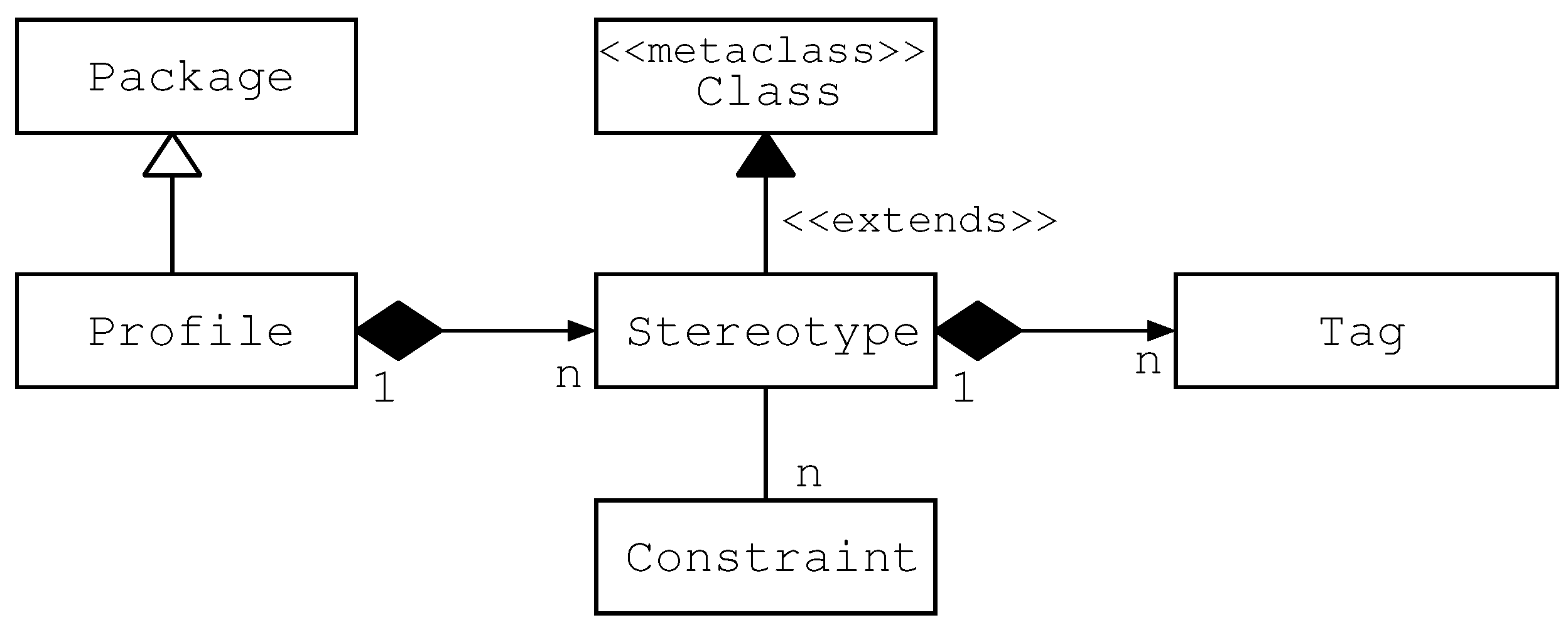
7], a UML profile is made of a set of stereotypes, a set of tags and a set of related constraints. A stereotype is just a name that is attached to elements of a UML diagram. Stereotypes have tags, which can be seen as the attributes of the stereotype. A constraint expressed in OCL [37] can be attached to a stereotype definition, describing restrictions for the stereotype. Figure 1 goes deeper into the profile definition. Therefore, stereotypes are of primary importance and they are applied to model elements directly; this is possible because a stereotype extends a UML meta-class, as we can see in Figure 1.

3. MARTE Profile

The MARTE profile [29], shown in Figure 2, contains three packages: MARTE Foundations, MARTE Design Model and MARTE Analysis Model. MARTE Foundations proposed in [29] offers concepts defining the basic behavior in real-time systems, a framework for NFP annotation, both quantitative and qualitative, a time model, a resource model and a causality model. MARTE Design Model offers concepts for modeling aspects, such as concurrency and synchronization, in real-time systems, as well as a component model for this field. MARTE Analysis Model is the package for analysis, in particular, it defines profiles for schedulability (SAM) and performance analysis (PAM), as extensions of the GQAM profile, which DAM also specializes. Finally, MARTE offers (a) the VSL profile, for describing the particular values associated to NFP, and (b) the MARTE Library, which defines the units of measures and offers data types and pre-defined NFP types.
In the following, we first discuss basic concepts in the real-time field as described in MARTE [29], then describe the functionalities of the NFP profile.

3.1. Basic Concepts in the Real-Time Domain

Time, events and resources are among the most important concepts in the real-time domain [38], and MARTE offers a general framework for their representation and modeling as follows. Physical time is assumed to progress monotonically and in a forward direction, and it is the base for scheduling issues in critical systems. The time is assumed to be an ordered set of instants. For measuring the progress of physical time, clocks are introduced, which can be physical or logical. Events can occur in the system causing the execution of behaviors. Time and behavior are tightly coupled in MARTE. Events are associated to instants of time. Sometimes, events can be considered as a whole since their collective effect is the same as the serialization of their individual ones. A resource is an entity, physical or logical, that offers one or more services. Resources provide a platform for the real-time system to be executed, and they can be software or hardware. Resources and services are the means to satisfy the system requirements. The functional elements of the system need to be allocated, both spatially and temporally, onto available resources. The spatial allocation means the mapping of (a) computation elements to processing elements, (b) data to memory and (c) data/control to communication resources. The temporal allocation means the temporal ordering of the computations. MARTE distinguishes resources as follows:
  • ExecutionHost: the machine where the operating system processes execute;
  • CommunicationsHost: for ensuring the connection of computing nodes;
  • SchedulableResource: the threads and process managed by the operating system;
  • CommunicationChannel: the links dispatching messages.
Finally, scenarios provide the means for steps (computational activities) to be executed by components, that act as resources for providing the system services.

3.2. Specification of NFP

The MARTE NFP profile is defined in [29] for specifying NFPs and their constraints and relationships in UML diagrams. It uses the VSL (value specification language) profile, which offers a particular grammar for the NFP specification of data types, values and expressions. Extracted from [29], the NFP package realizes the following set of functionalities:
  • NFP qualitative or quantitative nature. A quantitative property may be characterized by a set of measures expressed in terms of magnitude and unit.
  • Variables and expressions, beside concrete values, raise the level of abstractions of the specified properties, allowing to derive ones from others.
  • Trade-off between usability and flexibility. Usability suggests the merit of declaring a set of standard property types and their available operations for a certain domain, while flexibility allows for user-defined properties.

4. Dependability Modeling with UML

DAM, as a specialization of MARTE, was conceived for the modeling of real-time systems and specifically to address dependability analysis. The approach for obtaining these features was to create extensions, basically stereotypes, constraints and tags, and a library. Instead of building it from scratch, DAM leveraged MARTE and specialized its stereotypes. Figure 3 depicts the architecture of DAM, which is made of the following packages.

4.1. DAM Library

This library offers types, basic and complex, for defining dependability NFPs using some MARTE packages: (a) the NFP profile defined in Section 3, which helps to define some new types; (b) the VSL, which offers complex types; and (c) the MARTE library, that helps to define both dependability types, basic and complex.

4.1.1. Basic Dependability Types

These are simple enumeration types and new data types:
  • Simple enumeration types are used to describe properties of the system threats. DAM uses the definitions in [4,13] to offer the types in Table 1.
  • Data types are new NFP types. They leverage different types from MARTE, as depicted in Figure 4, and must be described using the following requirements:
    -
    expr: An expression in MARTE Value Specification Language (VSL).
    -
    source: Describes the origin of the NFP. It can be an estimated metric, a requirement to be satisfied, calculated or measured.
    -
    statQ: The type of statistical measure (e.g., maximum, minimum, and mean).
    -
    dir: Used for comparison in analyses, it is useful to define an order relation.

4.1.2. Complex Dependability Types

As in MARTE, they are tupleTypes and can be characterized either by basic NFPs or basic dependability types or complex dependability types. Most of the attributes of a complex dependability type have “*” multiplicity, meaning that either zero or more values can be assigned to them. Complex types are useful for describing characteristics of the system, such as threats, but also for describing the properties of the main dependability mechanisms, such as recovery and repair strategies. DAM prefixes this type as Da. Figure 5 depicts these types.

4.2. DAM UML Extensions

DAM extensions provide a set of stereotypes, attributes and constraints to domain experts, who need to represent a system dependability view. Hence, DAM can be applied at the model specification level. DAM provides stereotypes useful to be applied in different modeling situations. In the following, we describe all DAM stereotypes. They are grouped by their modeling purpose.

4.2.1. Basic Stereotypes

They allow to describe the dependability properties of the main modeling elements of a system, such as its components (e.g., classes, subsystems or packages), connectors (e.g., associations or communication links) or the system steps (e.g., activities). The basic stereotypes are summarized in Table 2, Table 3, Table 4, Table 5 and Table 6: each table describes the basic stereotype (in bold), together with its generalization, the extended UML meta-classes, its attributes and, in case, the constraints on its attributes.

4.2.2. Stereotypes for Modeling System Threats

The threats of the system, as defined in [4], are faults, errors, failures and hazards. They are defined in DAM as complex dependability types, see Section 4.1.2. For a complete modeling of the threats, it is also needed to characterize the error propagation (Table 7) and the generation of faults (Table 8).

4.2.3. Stereotypes for Modeling Maintenance Activities

Repairable systems need maintenance activities. While these activities are executing, the system may not deliver service. The stereotypes are detailed in Table 9, Table 10, Table 11 and Table 12.

4.2.4. Stereotypes for Modeling System Redundancy

These stereotypes offer support for an eventual quantitative dependability analysis of a fault-tolerant system. The purpose is to model redundant structures that can support such analyses. For modeling system redundancy, we have DaAdjudicator, DaVariant, DaRedundantStructure, DaSpare and DaController detailed in Table 13Table 14Table 15Table 16, and Table 17, respectively.

5. Case Study

Pai and Dugan reported in [16] a study in the mission and safety-critical embedded systems field, with the goal of analyzing system dependability properties. Concretely, they developed UML models for a mission avionic system (MAS) and derived a dynamic fault tree. In [11], we revisited the MAS specification of Pai and Dugan for adapting its models to the concepts proposed by DAM. Herein, we recall the MAS case study for illustrating a modeling approach using DAM. Since the task of annotating UML models with dependability properties is complex and requires some expertise, this example can be used by practitioners as a blueprint.

5.1. System Description

MAS are conceived to be reconfigurable and highly redundant. Redundancy is always considered at software and hardware levels. The MAS proposed in [16] consists of five sub-systems. Each subsystem aggregates a set of components, which execute on different devices, see Figure 6. The software components addresses the control tasks as follows: the crew station by CrewStnA and CrewStnB, the obstacles and scene by S&OA and S&OB, the generation of the paths by PathGenA and PathGenB, the system management by SysMgtA and SysMgtB and the vehicle management by VM1A, VM1B, VM2A and VM2B. For clarity, primary processing modules are postfixed as A, while modules representing hot spares are postfixed as B.
For ensuring dependability, redundancy mechanisms are introduced in the system as backups, both hot and cold spares. Hot spare modules (e.g., S&OB) take control when a failure or error occurs, and it is detected by its corresponding primary unit (e.g., S&OA). Regarding the component managing the vehicle, it uses two processing devices, which account for a backup, in the form of a hot spare, each. Regarding cold spare backups, they are activated when two failures occur simultaneously. The cold spare backups are named Spare1, Spare2 for four of the subsystems, and VMSp1, VMSp2 for the vehicle management subsystem. The busses that interconnect the sub-systems own their redundancy mechanisms also. Among them, the mission management bus (MMBus) that interconnects all the subsystems is triplicated. The component managing the vehicle duplicates the bus (VMBus). The bus, called B/G Data Bus, connecting memory units Memory1 and Memory2, is also triplicated.
Reconfigurability is the other dependability mechanism used for reinforcing the MAS. In fact, some of the components have alternate minimal software versions, such as the controllers for the obstacles and the scene, as well as the one for generating the paths. The goal is to provide reduced functionality, obviously requiring fewer computing resources. Concretely, only one processor, instead of the two required for the full version. Finally, according to the failure assumptions made by Pai and Dugan, the system can fail in different situations: (a) if any of the subsystems do not properly work; (b) if both the memories fail; or (c) if all the busses fail.

5.2. Dependability Modeling of the MAS with UML

From the previous system description, we modeled different UML diagrams to represent the different system views of interest. The UML package diagram in Figure 7 represents the block diagram in Figure 6. Each package accounts for a subsystem, and each dependency relationship represents a relation among packages.
In the following, we first describe how UML profile annotations are applied to the elements of the model. Then, starting from UML models, we use the DAM profile to model the redundancies in the system, the input parameters for the reliability analyses and reconfiguration activities.

5.2.1. Usage of Profiles Stereotypes

MARTE and DAM stereotypes can be applied to the MAS UML models already developed. In this way, we can obtain the MAS dependability view. In particular, at the model specification level, a stereotype is applied to a concrete element of the model, provided that it belongs to a UML meta-class extended by such stereotype. For example, in Figure 7 the DaComponent stereotype is applied to the memory sub-system. This is possible because DaComponent specializes the MARTE::GRM::Resource stereotype and the latter extends the UML::Classes::Kernel::Classifier meta-class. Being that the memory sub-system is modeled as a UML class, in fact as an instance of the classifier meta-class, it can be stereotyped as DaComponent.
When a model element is stereotyped, it inherits the properties of the stereotype, that is, its tags. Then, the stereotyped model element can be annotated by assigning values to the tags (namely tagged-values). The values must conform to the type associated to the tag. For example, the memory sub-system in Figure 7 is annotated with several tagged values to specify its origin, i.e., hardware component (origin = hw tagged-value), the number of memories (resMult = 2 tagged-value) and its failure characteristics (failure = occurrenceRate = (value = 1 × 10 6 , unit = fail/yr). In particular, the origin tagged value is an enumeration, the resMult is an integer, and the failure tagged value is a complex dependability type (cf. Section 4).

5.2.2. Redundancy Modeling with DAM

One of the important features of the dependability view concerns the modeling of the redundancy. We have three different redundancy constructs in the MAS case study: replicated resources, redundant structures and cold spare components. They are represented in Figure 7. Regarding the replicated resources, we have busses and memories. Resources are stereotyped as DaComponent, whose tag resMult represents the number of replicas. For example, resMult = 3 indicates three replicas of the BGDataBus, while resMult = 2 indicates that the Memory is duplicated. Regarding redundant structures, each sub-system constitutes one of them. DaRedundantStructure is the stereotype used to label packages representing subsystems; hence, the tag FTlevel can be used to specify the fault-tolerance level of such a subsystem. This levels means the minimum number of components for a redundant structure to work. The DaSpare stereotype labels spare components. The tag dormancyFactor = 1 specifies the kind of spare (hot spares in this case). The tag resMult can also be used for spare components since this tag belongs to the DaComponent stereotype, a superclass of DaSpare. Finally, the tag substitutesFor indicates a list of components that can substitute for this spare component.

5.2.3. Reliability Input Parameters

We want to compute the failure rate of each component and the probabilities of the error propagation. These input parameters can be annotated using the DAM profile. The former is specified, using DaComponent or DaSpare stereotypes, with the tag occurrenceRate (see Figure 7). The latter are attached instead to the association or dependency relations, which are stereotyped as DaConnector. For example, we assign the probability of error propagation of 10 3 to the association between BGDataBus and Spare: since the error propagation is bidirectional (i.e., from the bus to the spare and vice versa), the tags from and to them, which enable indicating the source and the target components, are omitted.

5.2.4. Reconfiguration

Reconfiguration comprises strategies that the engineer designs to be implemented when failures in the system occur. The objective is to bring the system to a gracefully degraded state in which the basic functionalities can still be provided; therefore, activities for the replacement and/or reallocation of system components need to be carried out. In order to have a proper representation of the system reconfiguration, both the reconfiguration static view and its behavioral counterpart should be designed. In UML, we have the class diagram, object diagram and deployment diagram for addressing the static view. For the MAS, we chose the deployment since it allows us to represent the hardware elements involved in the reconfiguration as well as the mapping of the software components into this hardware. Regarding the behavioral view, UML offers a rich set of diagrams, among them being the activity, sequence and state machines. We chose the UML state machine diagram for describing the reconfiguration activities since it enables to capture reconfiguration events explicitly. Let us briefly describe both reconfiguration views for the MAS in the following.
The static view, deployment diagram in Figure 8, depicts the components for the control of the scene and the generation of the paths. Components providing full versions are stereotyped as DaComponent, while the ones providing minimal functionalities are DaVariant. The full and minimal versions are joined in a DaRedundantStructure package and mapped to processors (primary and spare). The hardware redundancy, although modeled in the class diagram, is also specified here using DaComponent and DaSpare stereotypes.
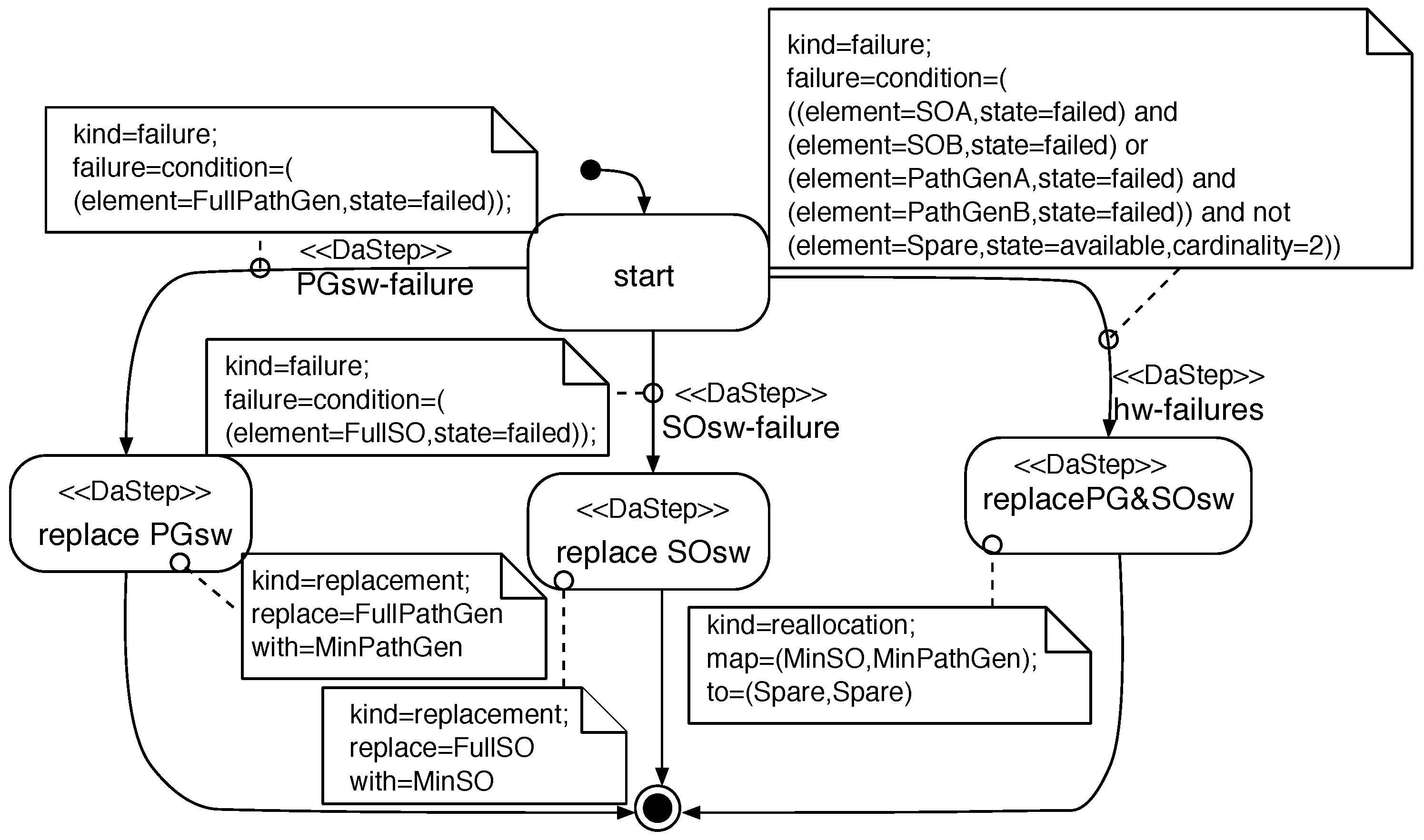
The behavioral view state machine in Figure 9 describes the actions to take when the full versions of the software need to be replaced by the minimal ones. Replacement occurs (a) if a software failure occurs, i.e., the modules fail, and (b) if a hardware failure occurs, i.e., the two processors fail (primary and spare). The software failure events, PGsw-failure and SOsw-failure, lead to states replacePGsw and replaceSOsw, respectively, where replacement activities are carried out. The hardware failure event hw-failures goes through state replacePG&OSsw to replace the full versions by minimal ones, which run on a single spare processor. Failure conditions for triggering failure events, hardware and software, are modeled in the transitions that go through reconfiguration states, which are labeled as DaStep, and they indicate either replacement or reallocation.

6. Conclusions

Advances in modeling software systems are needed by developers as the software complexity increases. However, in general, the scientific literature is far from the needs of the practitioners. Regarding non-functional properties and the modeling of dependability, many advances have been proposed. Among them, DAM is a UML profile that provides a complete framework for dependability. The purpose of this work is to highlight for practitioners the modeling approach of dependability taken in DAM. In this regard, we had to recall the UML profiling mechanism and to briefly describe the MARTE profile for the modeling and analysis of real-time and embedded systems. Finally, it is worth noting that modeling is only the first step for carrying out a dependability assessment of the system. The subsequent step, after modeling, is the dependability analysis. Besides modeling, DAM also offers the capability to address the dependability analysis of software systems, but analysis is out of the scope of this paper. Extensive literature in this regard can be found in [39].

Author Contributions

Conceptualization, S.B., J.M. and D.C.P.; methodology, S.B. and J.M.; validation, S.B., J.M. and D.C.P.; formal analysis, S.B.; investigation, S.B., J.M. and D.C.P.; data curation, S.B.; writing—original draft preparation, S.B., J.M. and D.C.P.; writing—review and editing, S.B., J.M. and D.C.P. All authors have read and agreed to the published version of the manuscript.

Funding

S.B. and J.M. have been funded by project PID2020-113969RB-I00 of the Spanish Ministry of Science and Innovation.

Conflicts of Interest

The authors declare no conflict of interest.

Abbreviations

The following abbreviations are used in this manuscript:
DAMDependability Analysis and Modeling
DSMLDomain-Specific Modeling Language
MARTEModeling and Analysis of Real-Time and Embedded Systems
MDDModel-Driven Development
NFPNon-Functional Property
UMLUnified Modeling Language
RTESReal-Time Embedded System

References

  1. Boehm, B.W. A spiral model of software development and enhancement. Computer 1988, 21, 61–72. [Google Scholar] [CrossRef]
  2. Sommerville, I. Software Engineering, 10th ed.; Pearson: London, UK, 2015. [Google Scholar]
  3. Chung, L.; Nixon, B.A.; Yu, E.; Mylopoulos, J. Non-Functional Requirements in Software Engineering; Springer Science & Business Media: Berlin/Heidelberg, Germany, 2012; Volume 5. [Google Scholar]
  4. Avizienis, A.; Laprie, J.C.; Randell, B.; Landwehr, C. Basic Concepts and Taxonomy of Dependable and Secure Computing. IEEE Trans. Dependable Secur. Comput. 2004, 1, 11–33. [Google Scholar] [CrossRef] [Green Version]
  5. Schmidt, D.C. Guest Editor’s Introduction: Model-Driven Engineering. IEEE Comput. 2006, 39, 25–31. [Google Scholar] [CrossRef]
  6. Brambilla, M.; Cabot, J.; Wimmer, M. Model-Driven Software Engineering in Practice, 2nd ed.; Synthesis Lectures on Software Engineering; Morgan & Claypool: Drive San Rafael, CA, USA, 2017. [Google Scholar] [CrossRef]
  7. OMG. Unified Modeling Language (UML), Version 2.5.1; Document Number: Formal/2017-12-05; OMG: Needham, MA, USA, 2017. [Google Scholar]
  8. OMG. OMG Systems Modeling Language (SysML), Version 1.6; Document Number: Formal/2019-11-01; OMG: Needham, MA, USA, 2019. [Google Scholar]
  9. Vesely, B. Fault Tree Analysis (FTA): Concepts and Applications. NASA HQ 2002. Available online: http://ismss.ru/uploads/8-5-1.pdf (accessed on 20 February 2022).
  10. Ajmone Marsan, M.; Balbo, G.; Conte, G.; Donatelli, S.; Franceschinis, G. Modelling with Generalized Stochastic Petri Nets; Wiley Series in Parallel Computing; John Wiley and Sons: Hoboken, NJ, USA, 1995. [Google Scholar]
  11. Bernardi, S.; Merseguer, J.; Petriu, D. Model-Driven Dependability Assessment of Software Systems; Springer: Berlin/Heidelberg, Germany, 2013. [Google Scholar]
  12. Bernardi, S.; Merseguer, J.; Petriu, D. A dependability profile within MARTE. Softw. Syst. Model. 2011, 10, 313–336. [Google Scholar] [CrossRef] [Green Version]
  13. Leveson, N.G. Safeware; Addison-Wesley: Boston, MA, USA, 1995. [Google Scholar]
  14. Grunske, L.; Kaiser, B.; Papadopoulos, Y. Model-Driven Safety Evaluation with State-Event-Based Component Failure Annotations. In Proceedings of the Eighth International Symposium on Component-Based Software Engineering, St. Louis, MO, USA, 14–15 May 2005; Springer International Publishing: Berlin/Heidelberg, Germany, 2005; Volume 3489, pp. 33–48. [Google Scholar] [CrossRef]
  15. Cortellessa, V.; Singh, H.; Cukic, B. Early reliability assessment of UML based software models. In Proceedings of the WOSP02: Workshop on Software and Performance (Co-Located with ISSTA 2002 ), Rome, Italy, 24–26 July 2002. [Google Scholar]
  16. Pai, G.J.; Dugan, J. Automatic Synthesis of Dynamic Fault Trees from UML System Models. In Proceedings of the I13th International Symposium on Software Reliability Engineering (ISSRE-02), Annapolis, MD, USA, 12–15 November 2002; pp. 243–256. [Google Scholar]
  17. Cortellessa, V.; Pompei, A. Towards a UML profile for QoS: A contribution in the reliability domain. ACM SIGSOFT Softw. Eng. Notes 2004, 29, 197–206. [Google Scholar] [CrossRef]
  18. Goseva-Popstojanova, K.; Hassan, A.; Guedem, A.; Abdelmoez, W.; Nassar, D.E.M.; Ammar, H.; Mili, A. Architectural-level risk analysis using UML. IEEE Trans. Softw. Eng. 2003, 29, 946–960. [Google Scholar] [CrossRef]
  19. Becker, S.; Koziolek, H.; Reussner, R. The Palladio component model for model-driven performance prediction. J. Syst. Softw. 2009, 82, 3–22. [Google Scholar] [CrossRef]
  20. Brosch, F.; Koziolek, H.; Buhnova, B.; Reussner, R. Architecture-based reliability prediction with the palladio component model. IEEE Trans. Softw. Eng. 2011, 38, 1319–1339. [Google Scholar] [CrossRef]
  21. Calinescu, R.; Ghezzi, C.; Johnson, K.; Pezzè, M.; Rafiq, Y.; Tamburrelli, G. Formal Verification With Confidence Intervals to Establish Quality of Service Properties of Software Systems. IEEE Trans. Reliab. 2016, 65, 107–125. [Google Scholar] [CrossRef] [Green Version]
  22. Zhou, N.; Li, D.; Vyatkin, V.; Dubinin, V.; Liu, C. Toward Dependable Model-Driven Design of Low-Level Industrial Automation Control Systems. IEEE Trans. Autom. Sci. Eng. 2022, 19, 425–440. [Google Scholar] [CrossRef]
  23. IEC 61499-1:2012; Function Blocks. IEC: Geneva, Switzerland, 2012.
  24. Boyer, G.; Pétin, J.F.; Brinzei, N.; Camerini, J.; Ndiaye, M. Toward Generation of Dependability Assessment Models for Industrial Control System. In Proceedings of the 2019 International Conference on Information and Digital Technologies (IDT), Zilina, Slovakia, 25–27 June 2019; pp. 50–59. [Google Scholar] [CrossRef]
  25. Aizpurua, J.I.; Papadopoulos, Y.; Merle, G. Explicit Modelling and Treatment of Repair in Prediction of Dependability. IEEE Trans. Dependable Secur. Comput. 2020, 17, 1147–1162. [Google Scholar] [CrossRef]
  26. Papadopoulos, Y.; Walker, M.; Parker, D.; Sharvia, S.; Bottaci, L.; Kabir, S.; Azevedo, L.; Sorokos, I. A synthesis of logic and bio-inspired techniques in the design of dependable systems. Annu. Rev. Control 2016, 41, 170–182. [Google Scholar] [CrossRef] [Green Version]
  27. Ameller, D.; Franch, X.; Gómez, C.; Martínez-Fernández, S.; Araújo, J.; Biffl, S.; Cabot, J.; Cortellessa, V.; Fernández, D.M.; Moreira, A.; et al. Dealing with Non-Functional Requirements in Model-Driven Development: A Survey. IEEE Trans. Softw. Eng. 2021, 47, 818–835. [Google Scholar] [CrossRef] [Green Version]
  28. Ameller, D.; Galster, M.; Avgeriou, P.; Franch, X. A survey on quality attributes in service-based systems. Softw. Qual. J. 2016, 24, 271–299. [Google Scholar] [CrossRef] [Green Version]
  29. OMG. UML Profile for MARTE: Modeling and Analysis of Real-Time and Embedded Systems, Version 1.2; OMG Document: Formal/19-04-01; OMG: Needham, MA, USA, 2019. [Google Scholar]
  30. Selic, B. Using UML for modeling complex real-time systems. In Languages, Compilers, and Tools for Embedded Systems; Mueller, F., Bestavros, A., Eds.; Springer: Berlin/Heidelberg, Germany, 1998; pp. 250–260. [Google Scholar]
  31. Kelly, S.; Tolvanen, J.P. Domain-Specific Modeling: Enabling Full Code Generation; John Wiley & Sons: Hoboken, NJ, USA, 2008. [Google Scholar]
  32. France, R.; Rumpe, B. Editorial: Domain specific modeling. Int. J. Softw. Syst. Model. 2005, 4, 1–3. [Google Scholar] [CrossRef]
  33. Selic, B. A Systematic Approach to Domain-Specific Language Design Using UML. In Proceedings of the 10th IEEE International Symposium on Object and Component-Oriented Real-Time Distributed Computing (ISORC’07), Santorini, Greece, 7–9 May 2007; pp. 2–9. [Google Scholar] [CrossRef]
  34. Selic, B.; Gerard, S. (Eds.) Modeling and Analysis of Real-Time and Embedded Systems with UML and MARTE; Morgan Kaufmann: Boston, MA, USA, 2014. [Google Scholar]
  35. Booch, G.; Jacobson, I.; Rumbaugh, J. The Unified Modeling Language User Guide; Addison-Wesley: Upper Saddle River, NJ, USA, 2005. [Google Scholar]
  36. Fowler, M. UML Distilled: A Brief Guide to the Standard Object Modeling Language, 3rd ed.; Addison-Wesley: Boston, MA, USA, 2003. [Google Scholar]
  37. OMG. Object Constraint Language, Version 2.4; OMG Document: Formal/2014-02-03, v2.4; OMG: Needham, MA, USA, 2014. [Google Scholar]
  38. Douglass, B.P. Real Time UML: Advances in the UML for Real-Time Systems, 3rd ed.; Addison Wesley Longman Publishing Co., Inc.: Boston, MA, USA, 2004. [Google Scholar]
  39. Bernardi, S.; Merseguer, J.; Petriu, D. Dependability modeling and analysis of software systems specified with UML. ACM Comput. Surv. 2012, 45, 2. [Google Scholar] [CrossRef]
Figure 1. Profile definition.
Software 01 00007 g001
Figure 2. MARTE profile.
Software 01 00007 g002
Figure 3. DAM profile architecture.
Software 01 00007 g003
Figure 4. DAM basic dependability data types, taken from [11].
Software 01 00007 g004
Figure 5. DAM complex dependability types.
Software 01 00007 g005
Figure 6. MAS block diagram from [16].
Software 01 00007 g006
Figure 7. MAS architectural view, taken from [11].
Software 01 00007 g007
Figure 8. MAS reconfiguration: static view, taken from [11].
Software 01 00007 g008
Figure 9. MAS reconfiguration: behavioral view, taken from [11].
Software 01 00007 g009
Table 1. Simple enumeration types.
TypeValues
Capabilityaccidental and incompetence
Consistencyconsistent and inconsistent
CriticalLevelmarginal, minor, major and catastrophic
DaCurrencyUnitKindeuro and dollar
DaFrequencyUnitKindfaults/s, …, failure/yr, repair/s, …recovery/yr
Detectabilitysignaled and unsignaled
Domaincontent, earlyTiming, lateTiming, halt and erratic
FactorOriginendogenous and exogenous
Guidewordvalue, omission and commission
Intentdeliberate and non deliberate
Levelvery high, high, medium and low
Likelihoodfrequent, moderate, occasional, remote, unlikelyand impossible
Objectivemalicious and non malicious
Originhardware and software
Persistencytransient and permanent
PhaseCreationdevelopment and operational
PhenomCausenatural and human made
StepKindfault, error, failure, hazard, reallocation, replacement and activation
SysBoundariesinternal and external
Table 2. DaComponent stereotype.
DaComponentThis stereotype is useful for modeling the dependability properties of the system resources, both hardware and software.
GeneralizationMARTE::GRM::Resource
Extensionsnone
Attributes:
statefulBoolean[0..1] true (the component can be characterized by an error latency); false (the component is considered faulty)
originOrigin[0..1]-REVIEW—Hardware or software
isActiveBoolean[0..1]—Inherited from Resource
resMultInteger[0..1]—Inherited from Resource
failureCoverageNFP_Percentage[*]
percPermFaultNFP_Percentage[*]
ssAvailNFP_Percentage[*]—Steady-state availability
unreliabilityNFP_CommonType[*]
reliabilityNFP_CommonType[*]
missionTimeNFP_CommonType[*]
availLevelDaLevel[*]—Application specific
reliabLevelDaLevel[*]—Application specific
safetyLevelDaLevel[*]—Application specific
complexityNFP_Real[*]—Failure proneness
substitutedByDaSpare[*]—Spares substituting the component
faultDaFault[*]—Faults affecting the component
errorDaError[*]—Errors affecting the component
failureDaFailure[*]—Failures affecting the component
hazardDaHazard[*]—Hazards affecting the component
repairDaRepair[*]—Repairs undergone by the component
Table 3. DaConnector stereotype.
DaConnectorThis stereotype is used for describing the properties of the links, logical and physical, between system components.
Generalizationnone
ExtensionsAssociation, CommunicationPath, Deployment, Connector, InvocationAction, Dependency (e.g., Usage), Message, Extend, Include.
Attributes:
couplingNFP_Real[*]—coupling metric, related to error propagation proneness
errorPropDaErrorPropagation[*]—Error propagations carried by the connector
failureDaFailure[*]— Failures affecting the connector
hazardDaHazard[*]— Hazards affecting the connector
Table 4. DaService stereotype.
DaServiceThis stereotype represents the characteristics of the system services, which are provided and required by the system components.
ExtensionsNone
GeneralizationMARTE::GQAM::GaScenario
Attributes:
execProbNFP_Real[*]—Execution probability
ssAvailNFP_Percentage[*]—Steady state availability
instAvailNFP_CommonType[*]—Probability that the service is correct at time t
unreliabilityNFP_CommonType[*]
reliabilityNFP_CommonType[*]
availLevelDaLevel[*] —Application specific
missionTimeNFP_CommonType[*]
reliabLevelDaLevel[*] —Application specific
safetyLevelDaLevel[*] —Application specific
complexityNFP_Real[*]—Failure proneness
failureDaFailure[*]— Failures affecting the service
hazardDaHazard[*]— Hazards affecting the service
recoveryDaRecovery[*] —The actions to recover the service
Table 5. DaServiceRequest stereotype.
DaServiceRequestThe system delivers requests to its users and they are characterized by this stereotype.
Generalizationnone
ExtensionsClassifier (e.g. Actor), Lifeline, Interaction, InstanceSpecification
Attributes:
accessProbNFP_Real[*] Probability of a user access the service
serviceProbNFP_Real[*]{ordered}—The probability for the request to be served
requestsDaService[*]{ordered}—List of services requested
ConstraintsserviceProb is used to define an order for requests
Table 6. DaStep stereotype.
DaStepThis stereotype, which inherits from its counterpart in MARTE, is fundamental for describing the properties of the activities. It inherits from MARTE the duration of the activity, among others.
GeneralizationMARTE::GQAM::GaStep and DaService
Extensionsnone
Attributes:
kindStepKind—For knowing the kind of step
errorDaError[*]—The errors that affect the step
Table 7. DaErrorPropRelation stereotype.
DaErrorPropRelationAn error propagation may occur from a faulty component, then the error can reach other components which interact with the faulty one via connectors. This stereotype allows to characterize the expressions and terms of the propagation.
Generalizationnone
ExtensionsUML::Classes::Kernel::Constraint
Attributes:
propagationExprPropExpression—logical expression with errorProp terms
errorPropDaErrorPropagation[2..*]{ordered}—Error propagation terms
ConstraintsA sequence of dependencies specifies the propagation of the error.
Table 8. DaFaultGenerator stereotype.
DaFaultGeneratorA fault generator is a dependability mechanism that allows to inject faults in the system. This stereotype is useful to specify the maximum number of concurrent faults and the characteristics of such faults.
GeneralizationMARTE::GQAM:: GaWorkloadGenerator
Extensionsnone
Attributes:
numberOfFaultsNFP_Integer[*] = 1—Number of faults that concurrently affect system components. Default is one. Redefine the GaWorkloadGenerator concept pop
faultDaFault—Characterization of the generated faults
ConstraintsIf the number of faults is more than one then there are multiple faults.
Table 9. DaReplacementStep stereotype.
DaReplacementStepThis stereotype models the actions to replace faulty components.
GeneralizationDaStep
Extensionsnone
Attributes:
replaceDaComponent[*] {ordered}—The component that needs to be replaced
withDaSpare[*]{ordered}—The component replacing other component that fails
Constraintsthe order of replace corresponds to the order of with.
Table 10. DaReallocationStep stereotype.
DaReallocationStepThis stereotype is useful for modeling where the software components are reallocated.
GeneralizationDaStep
Extensionsnone
Attributes:
mapDaComponent[*] {ordered}—The component to be reallocated
toDaSpare[*]{sequence}—The spare component that hosts the reallocated component
Constraints(1) The reallocated DaComponents have origin = sw, (2) the DaSpares that host the reallocated ones have origin = hw, (3) the order of map corresponds to the order of to.
Table 11. DaActivationStep stereotype.
DaActivationStepWhen a component fails an activation step can be triggered to carry out the maintenance activities.
GeneralizationDaStep
Extensionsnone
Attributes:
priorityNFP_integer[0..1]—it is the priority assigned to the step in case of conflicts between several activation steps
preemptionNFP_Boolean[0..1]—if it is true the step can be preempted by another activation step with higher priority
causeDaStep[*] —the failure steps that trigger this step
agentsDaAgentGroup[*]—the agent group that carries out this step
Table 12. DaAgentGroup stereotype.
DaAgentGroupModels the group of agents that carry out the maintenance activities.
Generalizationnone
ExtensionsUML::Classes::Kernel::Classifier
Attributes:
skillSkillType [0..1]—either hw or sw technicians
correctnessNFP_Real[*]—probability to have a successful maintenance
agentNumberNFP_Integer[*]—number of agents in the group
Table 13. DaAdjudicator stereotype.
DaAdjudicatorAn adjudicator defines a consensus of several outputs of variants or applies an acceptance test.
GeneralizationDaComponent
Extensionsnone
Attributes:
errorDetecCoverageNFP_Percentage[*] —the error detection coverage associated
Constraintsorigin = sw
Table 14. DaVariant stereotype.
DaVariantA variant is a component that provides same service but using a different specification.
GeneralizationDaComponent
Extensionsnone
Attributes:none
Table 15. DaRedundantStructure stereotype.
DaRedundantStructureA redundant structure is a group of components.
Generalizationnone
ExtensionsUML::Classes::Kernel::Package
Attributes:
FTLevelNFP_Integer[*] —the minimum number of components in the redundant structure, required to still guarantee a service
commonMFailureDaFailure[*]
commonMHazardDaHazard[*]
Table 16. DaSpare stereotype.
DaSpareA spare is a backup component.
GeneralizationDaComponent
Extensionsnone
Attributes
dormancyFactorNFP_Real[*] —ratio between the failure rates in standby mode and in operational mode.
substitutesForDaComponent[*]—Component to be substituted by the spare
ConstraintsThe components must be DaComponent or sub-stereotypes.
Table 17. DaController stereotype.
DaControllerA controller is a component responsible of coordinating variant components.
Extensionsnone
GeneralizationDaComponent
Attributesnone
Publisher’s Note: MDPI stays neutral with regard to jurisdictional claims in published maps and institutional affiliations.

