Abstract
The automotive industry is experiencing a significant shift, transitioning from traditional hardware-centric systems to more advanced software-defined architectures. This change is enabling enhanced autonomy, connectivity, safety, and improved in-vehicle experiences. Service-oriented architecture is crucial for achieving software-defined vehicles and creating new business opportunities for original equipment manufacturers. A software update approach that is rich in variability and based on a Merkle tree approach is proposed for new vehicle architecture requirements. Given the complexity of software updates in vehicles, particularly when dealing with multiple distributed electronic control units, this software-centric approach can be optimized to handle various architectures and configurations, ensuring consistency across all platforms. In this paper, our software update approach is expanded to cover the solution space of the feature-based product line engineering, and we show how to combine our approach with product line engineering in creative and unique ways to form a software-defined vehicle modular architecture. Then, we offer insights into the design of the Merkle trees utilized in our approach, emphasizing the relationship among the software modules, with a focus on their impact on software update performance. This approach streamlines the software update process and ensures that the safety as well as the security of the vehicle are continuously maintained.
1. Introduction
The evolution of electrical/electronic (E/E) architectures involves a shift away from a decentralized system, where functions operate on dedicated traditional electronic control units (ECUs) with software tightly coupled to hardware and interconnected through a central gateway. This transition is progressing toward more centralized systems, characterized by dedicated domain controllers managing a specific set of functions within a particular area or domain [1]. Ultimately, the architecture has advanced for uses in software-defined vehicles (SDVs), where zonal controllers organize functions based on their locations in the vehicle and embrace a service-oriented architecture to meet the emerging automotive demands. These domains and zones encompass hundreds of functional modules, both within the vehicle and in the cloud. They cover a wide range of features, including infotainment, advanced driver assistance systems (ADASs), mapping, telematics, and third-party applications. Typical original equipment manufacturers (OEMs) interact with a multitude of software providers to build various capabilities of this new architecture
The development of this architecture introduces challenges associated with the need for ongoing updates and support to ensure that vehicles remain safe, secure, and up to date. We have introduced our Merkle tree-based software over-the-air concept (MT-SOTA) [2,3] to improve current methods, providing a solution tailored to the evolving architectures in software-defined vehicles that is also applicable to multiple variant ECUs. Our proposed solution offers a single comprehensive verification approach that simultaneously confirms the authenticity, integrity, compatibility, and coherence of a single software module in relation to other software modules in the vehicle. It enables greater flexibility and adaptability in managing and updating software modules within the vehicle, as well as implemented with resilience against attacks and support a high degree of efficiency and development.
The main focus of this study was exploring how design decisions of the Merkle tree affect the efficiency of updating the software modules. This is crucial as a large tree can increase the transferred supplementary vehicle authentication information (SVAI) needed for software module verification, while more multiple trees can require greater effort to maintain and manage at the OEM repositories and address complexities associated with simultaneously updating multiple software modules. In this paper, the fusion of our Merkle-tree-based approach for software updates with feature-based product line engineering is introduced, driven from the feature modeling concept and aimed at enabling seamless and continuous updates for automotive systems with modular variants. Then, additional studies are described to guide the construction of Merkle trees, particularly for scenarios with multiple trees. Metrics like software module complexity and coupling within a vehicle are analyzed to provide valuable insights to enhance the efficiency of our approach. This paper is organized as follows:
- Section 2 covers an overview of the emerging vehicle architectures and the challenges in dynamically updating selective software modules.
- Section 3 presents a summary of the related work on over-the-air software updates.
- Section 4 provides a summary of our proposed Merkle-tree-based approach to update software modules that are seamlessly deployed to the vehicle.
- Section 5 presents how our approach to updating software modules can be expanded to address the solution space of feature-based product line engineering, as well as explains how the Merkle tree can be designed based on the dependency among the software modules.
- Section 6 shows the results of our experiments.
- Section 7 concludes this paper with final remarks.
2. Background
The complexity of software in automotive systems has increased, and many features and services are used for autonomous driving, electrified vehicles, connected cars, entertainment, remote control, data reporting, and many others. This complexity jump has created new risks for securing software updates. If the software is monolithic, it is more difficult for an attacker to gain access to the ECU software and then to the vehicle assets. When software is decomposed into separate subfunctions and services, the attack surface has more opportunities as there are more updates performed on a vehicle. A malfunctioned update of the software can provide a conduit for attacks to spread through a vehicle, since software vulnerabilities in one image can be exploited to provide access to a vehicle. It is also difficult to align updates and patches across dependent modules and services. The typical OEMs constructing vehicle’s architecture interact with multiple software providers to build various capabilities. These providers, working on different services related to a specific function or feature, rarely coordinate their activities. Thus, it is the OEM’s responsibility to detect any incompatibilities before allowing any services to be used in a vehicle.
In modern vehicles, ECUs are organized into multiple functionally related domains or zones, which represent geographic or functional groupings of electrical features, networking modules, actuators, sensors, and real-time compute resources connected to central ECUs or central computers [4]. The introduction of central computers brings significant increases in computational power, enabling the support of artificial intelligence, vehicle personalization, and improved vehicle perception and vision systems. This system architecture not only significantly streamlines the interconnection of vehicle systems but also facilitates the deployment of software functionalities across ECUs. This architecture can be readily enhanced by integrating edge servers and clouds for collaborative purposes through wireless connections. The primary facilitator of the cloud-native design principle is the service-oriented architecture adopted in the automotive industry. This involves breaking down applications into self-contained functional services that can be deployed and orchestrated across computing devices. These services are commonly deployed as containers or virtual machines either in the vehicle or on the cloud. Feature- or service-oriented architecture is a structural methodology that emphasizes the development of a collection of reusable, self-contained software modules. These modules are designed to be accessible by various applications, platforms, and systems within the vehicle. They operate as independent modules and are typically integrated to form more complex applications or business processes. The authors of [5] proposed an on-demand redundancy concept using a flexible microservice architecture, which ensures the availability of the nonsafety components in a self-driving car to obtain higher availability and acts as a security measure if certain devices are experiencing a cyberattack. The authors of [6] proposed using container technology for better modularity and scalability. The authors of [7] adapted a container infrastructure for developing autonomous vehicles. Berger et al. [8] summarized experiences and best practices with using containers for self-driving vehicles. In [9], the authors proposed middleware techniques that focus on admission control, monitoring, and adaption to provide a reliable service-oriented communication infrastructure. The authors reported a case study consisting of three ECUs connected over one Ethernet switch. Two high-level functions (automated breaking and a rear-view camera) were realized over five software modules that were mapped to the ECUs. Another crucial factor in enabling this architecture is the modular software architecture, which primarily involves the logical organization of source code into related groups. This approach is reflected in many automotive platforms such as Autosar [10] and the OEM-dependent platforms [11,12]. Modern software architecture in the automotive industry is shifting toward a layered approach, which provides a standardized abstraction of vehicle functions. The middleware layer serves as a bridge between the application software and the underlying runtime software, also known as the software base layer [13]. The SDV requires an integrated backend and in-vehicle architecture, as exemplified in Figure 1. The feature-based development of application software leads to the creation of multiple short-lived source code branches. This sets the stage for continuous development and integration of innovations after delivery. The shift from occasional major updates to frequent minor ones has been a significant paradigm shift in software updates. ECU software development has typically adhered to the V model, which is a traditional approach to software development. This model typically involves a sequential process, where each phase must be completed before the next one can begin. However, there has been a significant shift toward continuous integration and deployment (CI/CD) services and DevOps methods [14] for automotive software development and operations. The combination of modular software architecture and the adoption of open-source, agile, and DevOps methods and practices support a more dynamic and flexible approach to ECU software development, ultimately leading to improved efficiency and better adaptation to changing requirements, market needs, and roll-out of features.
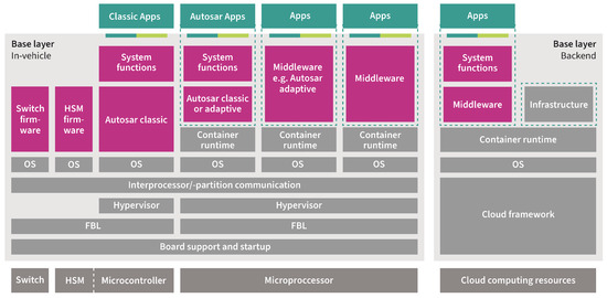
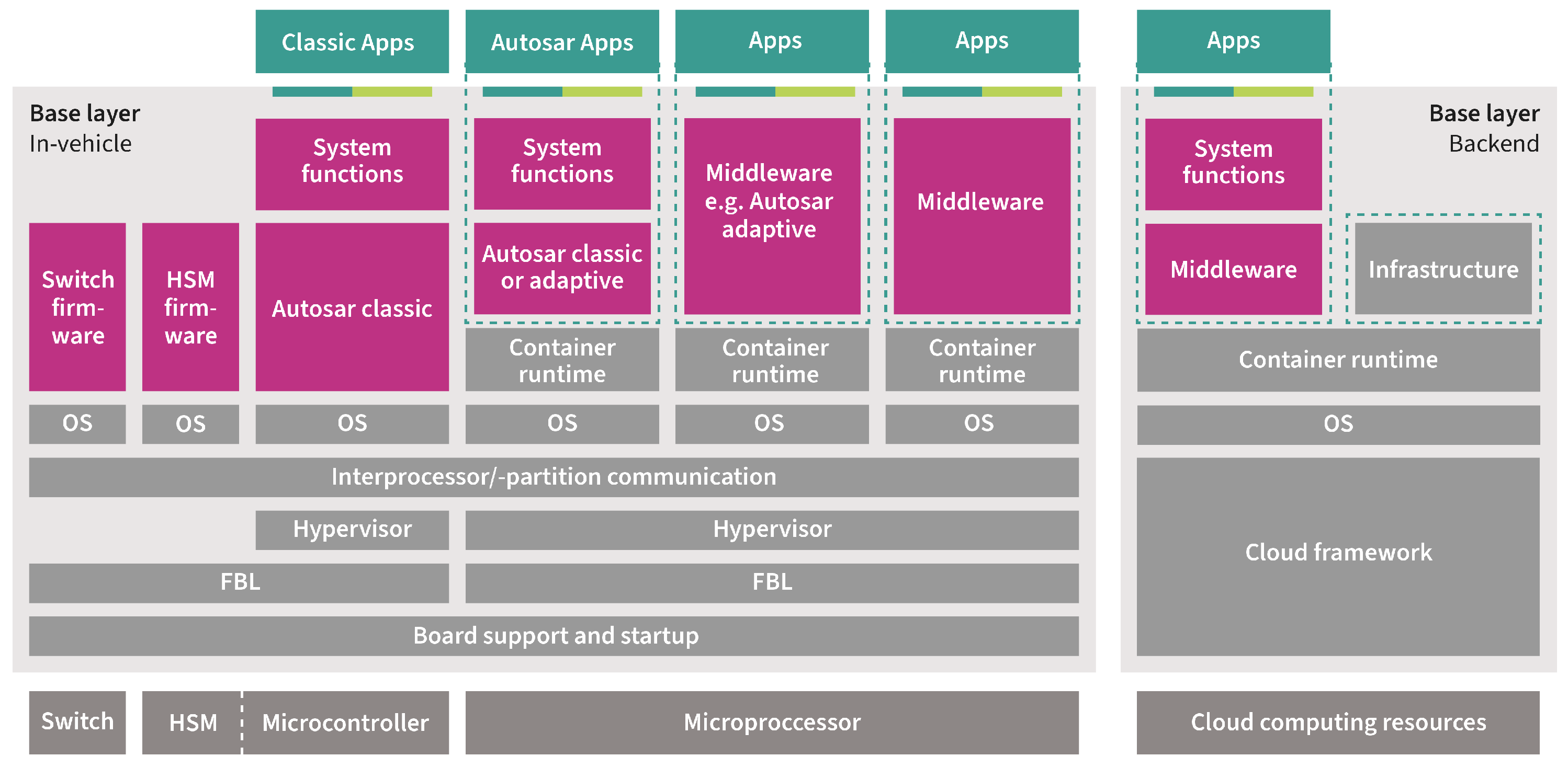
Figure 1.
Software-defined vehicle architectures, built upon core software layers and an operating system, in addition to the application software enhanced through cloud-based capabilities.
Feature-based product line engineering (PLE) [15,16] is a development approach that focuses on creating an application family by integrating a set of independently developed features. Essentially, feature-based PLE involves creating a set of reusable assets that can be combined and configured in various ways to meet the requirements of different applications or products. This approach enables OEMs to develop a diverse range of vehicles using the same set of core assets, reducing development time and cost while improving overall product quality and consistency. In the context of PLE, a feature is a distinct unit of functionality that can be combined with other features to create a product. The features are reusable and can be used in multiple products within a product line. Features are usually defined in a feature model, which provides a graphical representation of the features and their relationships. A feature model allows developers to define the dependencies between features and the constraints that govern their use. Using a feature-based approach, OEMs develop a range of vehicles that share a common set of features while still being able to tailor their offerings to meet the specific needs of end users. Feature modeling represents product line variability at the highest level of abstraction. Features express the high-level functional and quality requirements of variant-intensive systems.
A fundamental approach to SDV has been modularizing the software architecture by splitting the software into modules and services. SDV architectures require the independent deployment of a software module in the vehicle without deploying other software modules. A failure in one software module deployment should not impact the other software modules in the entire vehicle. Each software module is independently implemented, tested, and updated without altering the other software modules. In feature-based PLE, the focus is on sharing engineering assets across product lines. In feature-based software updates, the emphasis is on sharing software modules across vehicles. The motivation for combining Merkle-tree-based software update with PLE is that both approaches share a common goal: to enable the efficient and flexible management of complex systems. By integrating Merkle-tree-based software update with PLE, OEMs can leverage the benefits of both approaches to create a more efficient, scalable, and maintainable software development and deployment process.
3. Related Studies
The automotive industry has explored, standardized, and implemented various mechanisms for over-the-air (OTA) software updates in vehicles. These mechanisms encompass a wide range of approaches and range from comprehensive OTA update frameworks [17,18] to methods that employ hashing mechanisms [19], both symmetric and asymmetric cryptographic algorithms [20,21], a mix of online and offline cryptographic keys, and multiple levels of verification, which are achieved through both hardware and software solutions. SOTA approaches have been extended by using compression [22] and delta flashing [23] to reduce the network utilization and the bandwidth used for software updates. Digital signatures [24] have been established as one of the most vital and efficient methods for securing software updates in the automotive industry, mainly to ensure the authenticity and integrity of software updates. Traditionally, these techniques were designed for conventional ECUs, each handling a single software image per ECU. However, the emergence of advanced ECU architectures and software frameworks has created significant challenges for OEMs. They must now navigate the complexities of managing multiple software modules, ensuring they remain portable, consistent, and interoperable throughout the vehicle’s entire lifecycle, while also accommodating flexible deployment and updates. OEMs must therefore transition to a function-based or feature-based strategy, moving away from traditional approaches. As studied in [2,3], the Merkle tree software-based scheme (MT-SOTA) was proposed to verify the updated software image instead of the traditional ECU-based approach. MT-SOTA scheme illustrates the essence of secure software deployment and updates in the vehicle while enabling flexible and dynamic deployment of a software module in any ECU in the vehicle. The authenticity of each software is a critical point, since an attacker could, for example, pretend to be a provider and provide manipulated or malicious services. Software updates for modular and SDV-based architectures should be implemented so that they are resilient to any attack and support high degrees of efficiency and flexibility. The details of the MT-SOTA scheme is presented in the following section.
4. Merkle Tree Software-Based Approach
The Merkle tree software over-the-air (MT-SOTA)update scheme provides a robust mechanism for ensuring data integrity and security during updates, making it highly suitable for modern distributed systems and applications. This MT-SOTA uses a Merkle tree, a type of hash tree, and comprises two phases. In the first phase, the OEM repository is responsible for setting up the Merkle tree, generating the root and subsequently signing it. In the second phase, the ECU in the vehicle verifies the received signature to authenticate the received image. The following workflow outlines the MT-SOTA process, as illustrated in Figure 2:
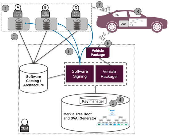
Figure 2.
Software over-the-air update workflow, extended with Merkle tree scheme: a single hash value is calculated and then signed with the private ECU key to generate a digital signature [2].
- The image software, SWMi, is stored in the image repository (ImgR).
- The ImgR provides the hash value of the software image, Hi (which is the output of hash (=SWMi)), along with additional manifest data for the OEM repository (OemR). These data are used to generate the signature.
- The OemR, which holds complete information about the vehicle, ECUs, and software modules, updates the corresponding Merkle tree to calculate the root and the supplementary vehicle authentication information (SVAI), . represents the authentication path that allows the ECU to reconstruct the Merkle tree root, which is a sequence of hash values corresponding to the siblings of the nodes along the path from the leaf node (the software module being updated) to the top root.
- The first set of hash results of the software images represents the leaf nodes in the hash tree at height 0.
- These nodes are combined in pairs to provide the first combined hash nodes. The value of the parent node is the hash of the concatenation of 2 child nodes’ hash (left ‖ right), where concatenation is represented by ‖.
- The hash results are further combined in pairs to an intermediate-level hash results. These intermediate-level hash results are repeatedly paired and combined until only a single combined hash result remains. This is the Merkle tree root.
- Using the private key assigned to the ECU where the software module is deployed, OemR signs the Merkle tree root to create the signature, , of the software image.
- OemR provides the generated signature and SVAI {, } to ImgR.
- OemR constructs the vehicle package containing the manifest data for the software images to be installed and then sends it to the OTA master, typically located in the telematics or gateway modules of the vehicles, wirelessly connected to the OEM repositories via wireless channels such as Wi-Fi or cellular communications.
- ImgR sends the software image appended with the signature and SVAI.
- Upon receiving the software image, Ecu reconstructs the Merkle tree with the hash of the received software image and the SVAI. It then determines whether the root tree is the same as the one received from the ImgR (after decrypting the received value with the public key of the ECU). Once verified, the ECU stores the value of the updated node, SVAI, and root node in the Merkle tree in a secure location.
Each software module is tailored to fit specific vehicle features or applications. Vehicles are typically structured around various domains or zones. The number of zones and their respective functions are based on the OEM vehicle’s design needs. Regardless of the structure, each category (domain, zone) can be represented by multiple subtrees rather than being restricted to a single tree. By employing this approach, software modules can be flexibly distributed to any ECU, resulting in increased adaptability and efficiency across the vehicle. The clustering of software modules with the most significant relationships can provide valuable insights into the trees and the allocation of the software modules within them. By leveraging relationship among the software modules, OEMs can gain valuable insights into the performance and behavior of vehicle software updates, assess their feasibility, and identify potential design issues prior to moving into the deployment phase. The objective is to partition the vehicle’s Merkle tree into distinct separate subtrees, as illustrated in Figure 3, to improve the performance of updating the software modules in the vehicle. These subtrees can be the same size or different sizes. For example, a tree of height HT can be divided into 2(HT−HTs) subtrees of height HTs. This split shortens the SVAI data length from HT to HTs for each software module update. However, the OEM needs to handle 2(HT−HTs) subtrees. By utilizing this approach, it becomes possible to reduce the height of the Merkle tree, leading to a decrease in the amount of SVAI data transferred. Consequently, this can enhance the overall performance when updating the software module within a vehicle.
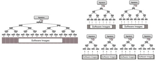
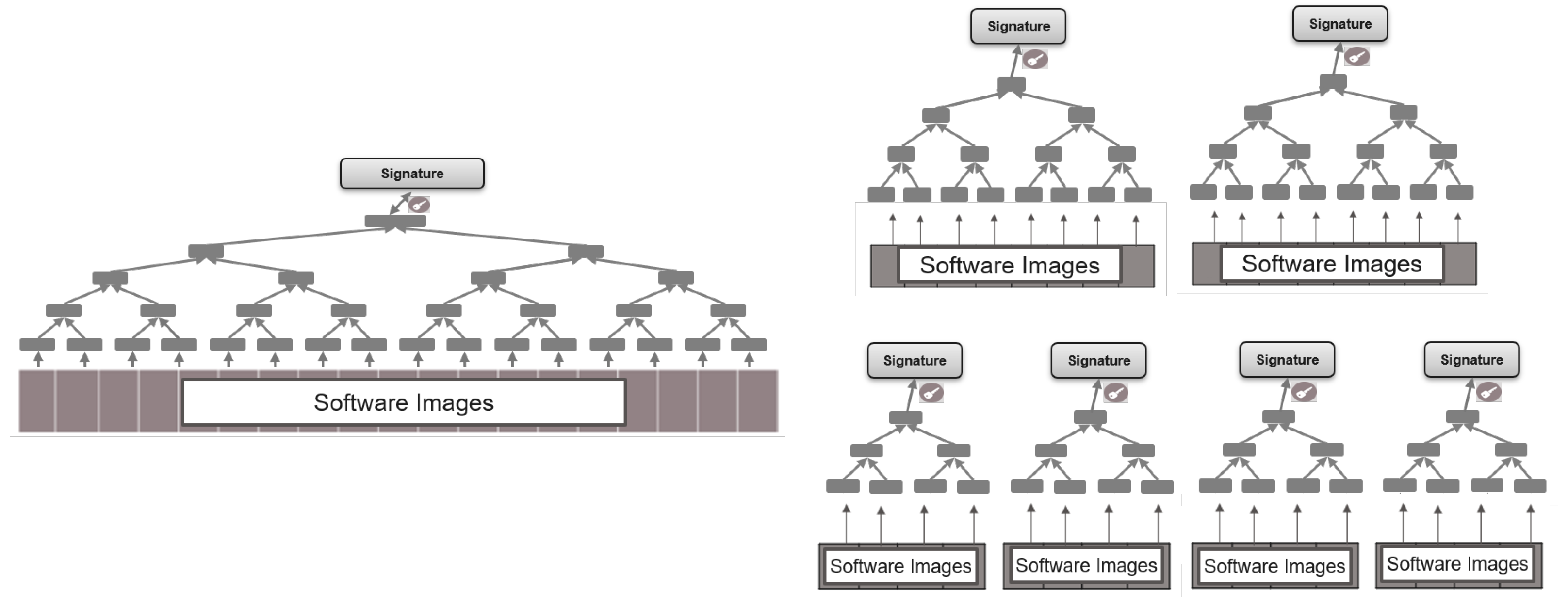
Figure 3.
Decomposition of a single Merkle tree into multiple Merkle trees of same or different heights. For equal Merkle tree sizes, the tree of height HT is divided into 2(HT−HTs) subtrees of height HTs.
5. Proposed Method
5.1. Feature-Based PLE Model Extension for Software Module Updates
The V model serves as a framework for the software development life cycle. It represents the progression of the software development process from requirement gathering and analysis to design, implementation, testing, and maintenance. PLE studies have mainly focused on the development activities on the left side of the V model and the slightly on part of the right side, mainly testing and validation. When it comes to building and updating software in a vehicle, software images have been made primarily using the “clone and own” method of reuse for software modules to create the specific build of the ECU based on the end-target ECU variant by maintaining multiple copies of software modules. To meet variant needs, the software of the baseline application is copied and then modified independently from the original software by adding or removing some feature implementations. For specific types of ECU, software images are created by combining software and configurations for multiple variant ECUs with an implicit build correlation among the ECUs.
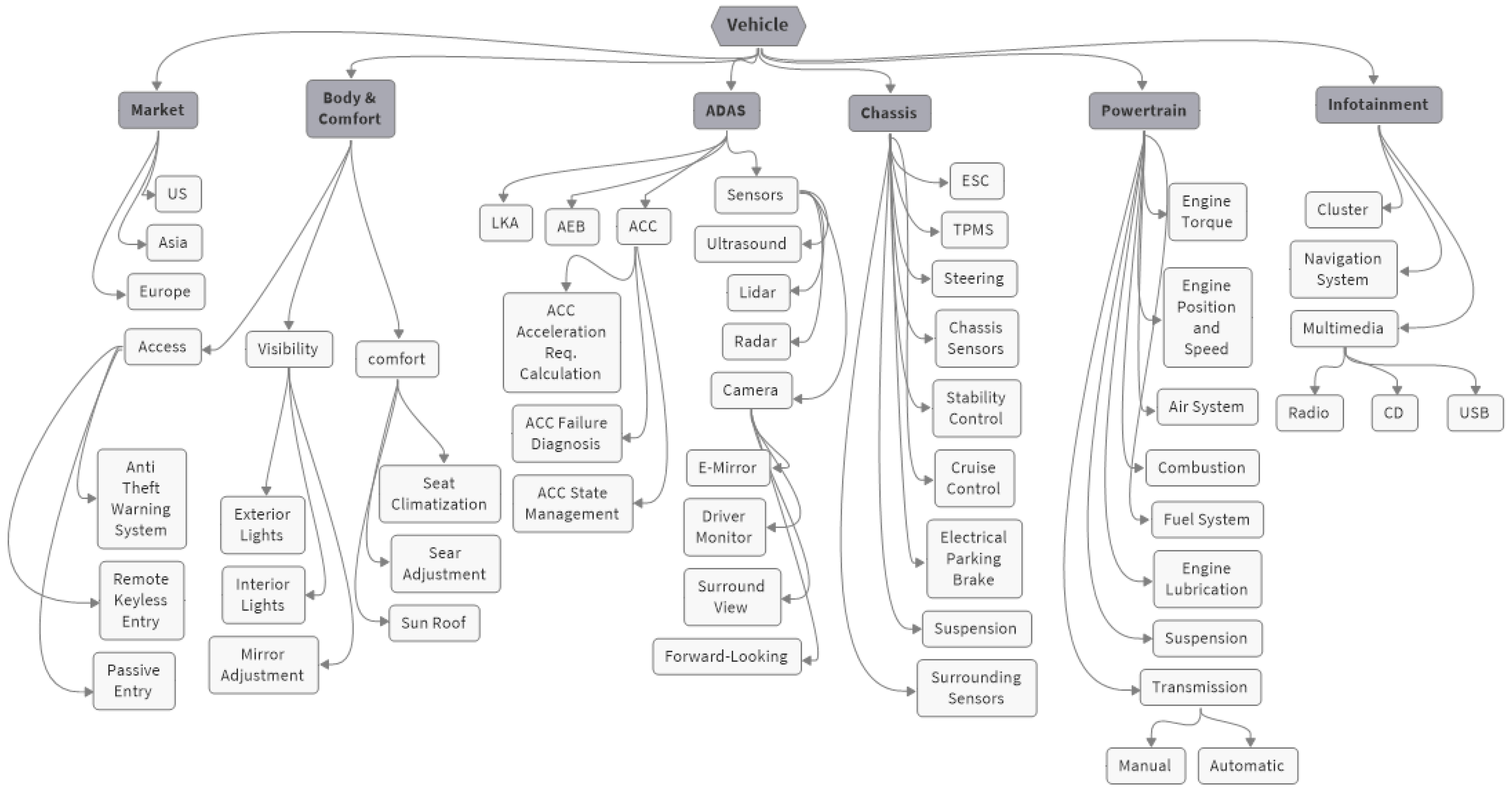
As discussed in Section 2, new paradigms are being adopted for the SDV architecture, which fundamentally change the methods of communicating and deploying software modules compared to those of the traditional approach. The software modules are shared across the vehicles. These shared modules are created and maintained as supersets, meaning that they contain any content needed to support any of the vehicles. A visual representation of various vehicle domains and functions is shown in Figure 4 within the context of key application domains such as chassis, body and comfort, powertrain, and ADAS. This illustration serves as an example and may not encompass all functions and features present in a vehicle. For instance, the chassis domain shows related features that are executed by the corresponding software modules. These modules have the capability of interacting with each other and with other domains within the vehicle. The relationships between the applications of the chassis domain and those of other domains are illustrated in Figure 5, as explained in [25]. In this case, the software module Vlc receives the longitudinal acceleration command from the software module CrsCtrlAndAcc. Subsequently, it distributes torque commands to the powertrain or brake system in order to fulfill the specified longitudinal acceleration command.
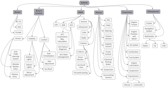
Figure 4.
Illustration of vehicle functions distributed across domains.
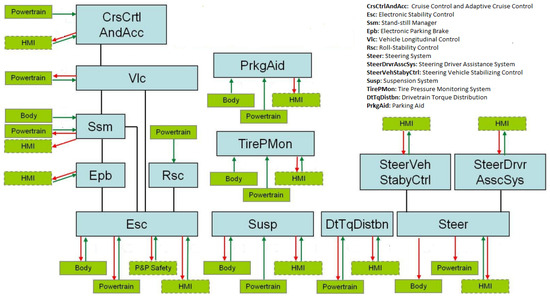
Figure 5.
An example of dependencies from each chassis software module to the applications of other domains. Each software module interacts with other software modules in the chassis domain as well as in the powertrain, human–machine interface (HMI), and body domains.
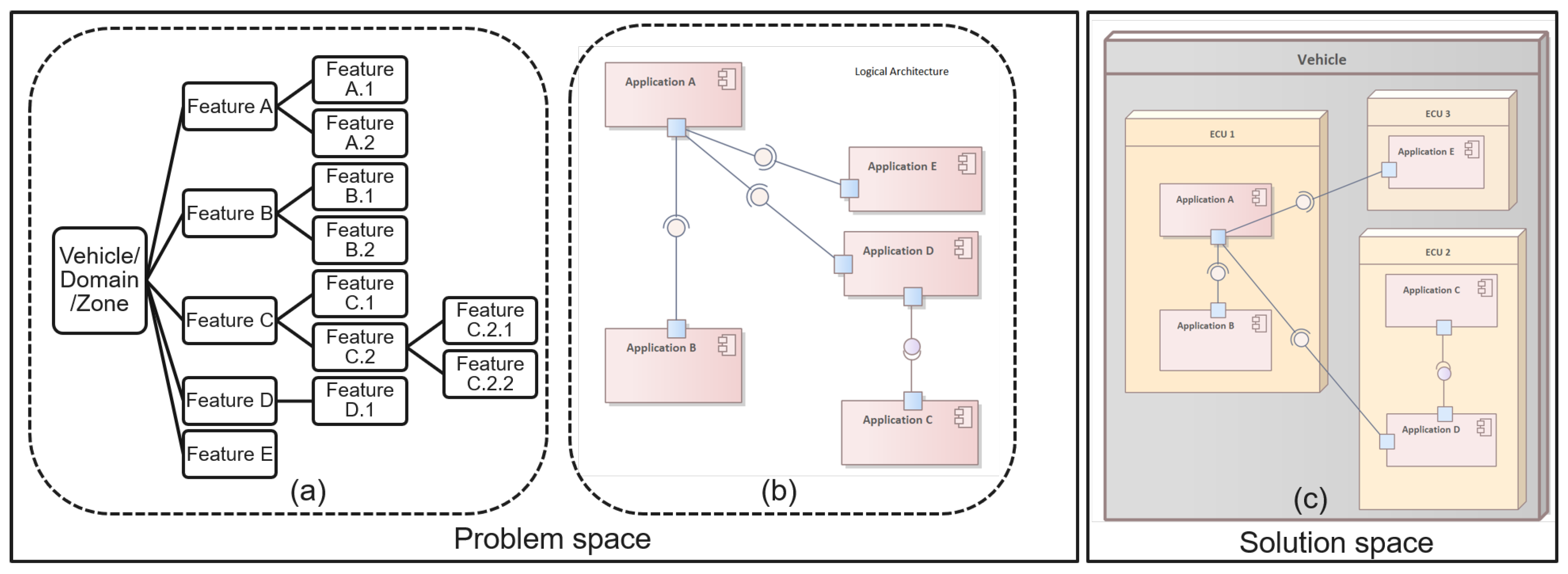
In a more generic view, the SDV software can be viewed from two perspectives: logically and physically. An example of the hierarchical organization of features is illustrated in Figure 6a, translated in a logical architecture in Figure 6b. The vehicle is subdivided into domains or zones that are clustered in accordance with their application areas, functionalities, or locations. These domains or zones are subsequently subdivided into subsystems, which, at the lowest level, consist of software modules. These software modules are then deployed physically in the ECUs in the vehicle, as shown in Figure 6c. The logical realms focus on selecting features, rather than specifying individual ECUs, signals and messages or software code. The key is to effectively map these feature to the underlying technical and software modules, ensuring that the ECUs function correctly and communicate with each other as intended. The process involves analyzing software modules from a logical perspective in order to rearrange the E/E functions within the vehicle. This entails sorting applications based on their specific domain, then segmenting and integrating them onto a domain or zone.
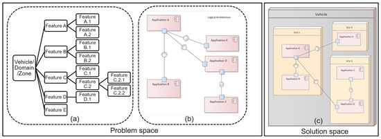
Figure 6.
Product line engineering separates the problem space from the solution space. A feature model of the vehicle product line is first provided to describe the relevant features and their relationship. Subsequently, these features are linked to software modules, which are then implemented in physical ECUs within the vehicle.
Product line engineering separates the problem space from the solution space. PLE can be visualized as a tree structure, where the trunk symbolizes the features of the vehicle product lines. The branches represent the specific features and requirements of a specific variant, which can be combined with the core assets to create a unique vehicle. With the PLE approach, OEMs can customize and scale their vehicles by selecting the appropriate features and requirements to meet the needs of different vehicles. A feature model is used to model the variability in this space. Additionally, a logical view of the 150% architecture model incorporating all modules, their refinement relations, and their contract specifications is included as part of the problem space. It is easily possible to derive the logical architecture of any variant selection. In the solution space, these features are linked to implementation models and implemented with concrete modules in the ECUs within the vehicle. Furthermore, we broaden the feature model of the problem space by incorporating additional features that define precise solution configurations, including software module versions as well as user and ECU configurations. SDV and SOA architectures complemented with our Merkle tree software update approach provide a way for OEMs to adopt the PLE concept for the deployment of software modules in vehicles. Leveraging feature-based PLE has been proven to decrease cost and improve scheduling and quality in various case studies. By adopting a feature-based PLE approach for software updates, OEMs can ensure efficient and consistent deployment across all vehicle variants. Our Merkle-tree-based approach addresses the solution space with a tree-based model to verify the updated software image instead of the traditional ECU-based approach. This initiative integrates PLE with the MT-SOTA scheme to enable a feature-driven approach to software deployment. When a feature is not selected for a vehicle, the associated software modules are automatically removed. Conversely, when a feature is assigned to a specific function, domain, or area, the required software modules are automatically allocated to the same function, domain, or area, ensuring a consistent and cohesive system. Figure 7 illustrates how our Merkle tree methodology offers OEMs an analogous technique for incorporating feature-based modeling for the distribution of software modules within the tree to verify software module updates in the ECUs across a vehicle. The Merkle tree is composed of a set of software systems that are designed and built based on a collection of features. A systematic mapping study serves as a method to determine the allocation of a software module to a specific Merkle tree, based on the feature attributes while taking into account the interactions among features, particularly when the behavior of one feature is affected by the existence of other feature(s).
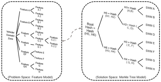
Figure 7.
Correlation between feature modeling and software module modeling in the vehicle: a detailed feature model was developed to define the different features and functionalities of the vehicle product line. Once the features are mapped and linked to the software modules, our Merkle tree approach offers OEMs a comparable method to embrace the feature-based PLE concept for deploying software modules in the physical ECUs across the vehicle.
As explained in Section 4, the SVAI must contain the complete details that allow the ECU to recalculate the Merkle tree root and verify the software image it receives. However, as the number of software modules increases, the height of the tree also increases, resulting in more SVAI data being transferred. As analyzed in [2], this leads to high communication costs and memory overhead. Thus, one optimization technique to consider is reducing the height of the Merkle tree to decrease the transferred SVAI data. This can be achieved by breaking down a single large tree into multiple smaller Merkle trees. Reducing the tree height can significantly decrease the amount of SVAI data transferred, leading to lower communication costs and memory overhead. Moreover, a smaller tree height results in a faster verification process, enhancing the efficiency of the approach. Additionally, working with smaller Merkle trees can simplify the implementation process, potentially reducing the complexity of the approach. This approach also allows mimicking the vehicle functions, domains, or regions, further streamlining the process. Thus, employing PLE and MT-SOTA together should consider the intended performance goals for updating the software modules. A vehicle’s modeled functionality is divided into domains or zones that offer features that exhibit behaviors or relations. These features are divided into subfeatures that enable the grouping of the software modules into different categories, which are mirrored in the solution space through the Merkle trees created to combine a set of software modules allocated to a specific category.
5.2. Methodology on Designing Merkle Trees for Software Updates
One of the key measures of the success of the SDV architecture is the effectiveness of software module changes. This refers to the impact that a single change made within a vehicle has on its applicability, whether it affects one or multiple shared feature set, indicating the potential impact of the change on the vehicle’s overall functionality. Every change in a software module affects the functionality of a feature in a single domain or multiple domains and zones in some number of vehicles in the field. The effectivity of the change measures, on average, how many vehicles are affected by a change made to the software module and eventually how the OEM can update these software modules efficiently and securely. Our research task in this study was to provide insights into the design of the Merkle tree of our approach [2] to improve performance, reduce the complexity of the computation algorithms, and reduce the cost of communication in the vehicle. Monitoring of the software module couplings using metrics was a crucial factor in our analysis. To achieve this, we propose focusing on three key objectives:
- Defining a strategy for metric collection: this process entails creating a blueprint for collecting specific metrics that are in harmony with the OEM architecture to identify software module dependencies;
- Analyzing the behavior of selected metrics and establishing a method for assessing the coupling metrics between software modules;
- Evaluating the proposed method through practical experimentation.
Software architecture is the fundamental organization of a system, embodied in its modules, their relationships to each other and the environment, and the principles governing its design and evolution [26]. Software architecture can also be seen as a shared understanding of how the system is structured and how its software modules relate to one another. As mentioned, a service-oriented architecture plays a crucial role in enabling and supporting SDVs by providing a flexible, scalable, and interoperable framework for the integration of diverse functions and services essential for the operation of vehicles. Service-oriented architectures have gained traction across a wide range of industries and have some similarities to the architectures of the new SDV automotive industry. The field of software engineering has shown that coupling and cohesion are fundamental dimensions of software complexity [27,28].
Although coupling and cohesion are typically employed to evaluate software integration, our approach seeks to repurpose these concepts in a distinct context. Coupling and cohesion are understood here in the sense of “measurable concepts”, rather than as specific measures. The concept of cohesion describes the degree of interdependence between the individual software modules in the vehicle, indicating how closely related they are to each other. It is a gauge of how much these software modules are related to each other in terms of functionality and purpose. It is an attribute that summarizes the degree of interdependence or connectivity among the software and within the vehicle or the domain and zone of the vehicle. A software module is coupled to another one if it invokes the other one’s services or data. Software modules can be coupled in different ways: directly, indirectly, or cyclically. Functional and nonfunctional requirements can lead to the coupling of software modules, often arising from their respective functions, types, or roles. As an example, Volvo introduced “Pedestrian Detection” technology to improve safety and prevent more than 50% of pedestrian-involved accidents. This safety system feature heavily depends on image processing software receiving data from onboard radar and camera systems. Thus, this image processing software is considered to be tightly coupled to the software in the radar and camera modules. Furthermore, indirect coupling can occur when a sensor reports a value to two different software modules, thereby creating a connection between these modules. These metrics do not take into account the complexity internal to each software module and considers a software module as a single entity. It is worth noting that the measures of architecture complexity can include the internal attributes for each OEM and the specific software architecture of the vehicle.
As automotive software development becomes more distributed, with separate suppliers developing software modules that are integrated by OEMs, the likelihood of hidden faults and issues emerging increases. This fragmented development approach can introduce complications and errors that may not arise until later in the development cycle. As a result, it is crucial to consider the cohesion and coupling of these software modules during their deployment in the vehicle to ensure that they function effectively and efficiently. In our context, the concept of cohesion indicates the degree to which the software modules work together to fulfill a single, well-defined feature or service, as well as by the fact that they depend heavily on each other to perform their respective functions. This is typically determined as follows:
- Domain or functionality: powertrain, chassis, infotainment, etc.;
- Safety level: QM, ASIL-A; through ASIL-D;
- Security relevance
- Role or type: diagnostics, calibration, OS, hardware dependency, sensors, actuators, etc.
- In order to perform a broad and inclusive analysis, the system is defined as follows:
- SW = {SW1, …, SWN} is a set of software modules, considering N software modules. M = {M1, …, Mm} is a set of metrics, considering m attributes.
- W = {W1,1, …, Wm,N} is the weight of the metric corresponding to the software module.
- The coupling, CM(i,j), for each software module SWi is given by:
- The coupling of all software modules is formulated as follows:
In addition to the coupling metric of the software modules concerning the defined attributes, the communication between the software modules is as important as the feature-based metrics. The concept of coupling indicates the communication and connections that take place between software modules. This refers to the frequency of service calls made or data exchanged between software modules or other in-between modules. Additional coupling between software modules (ACM) is considered and calculated based on the calls made or data exchanged between software modules. The ACM between 2 software module P and Q is formulated as follows:
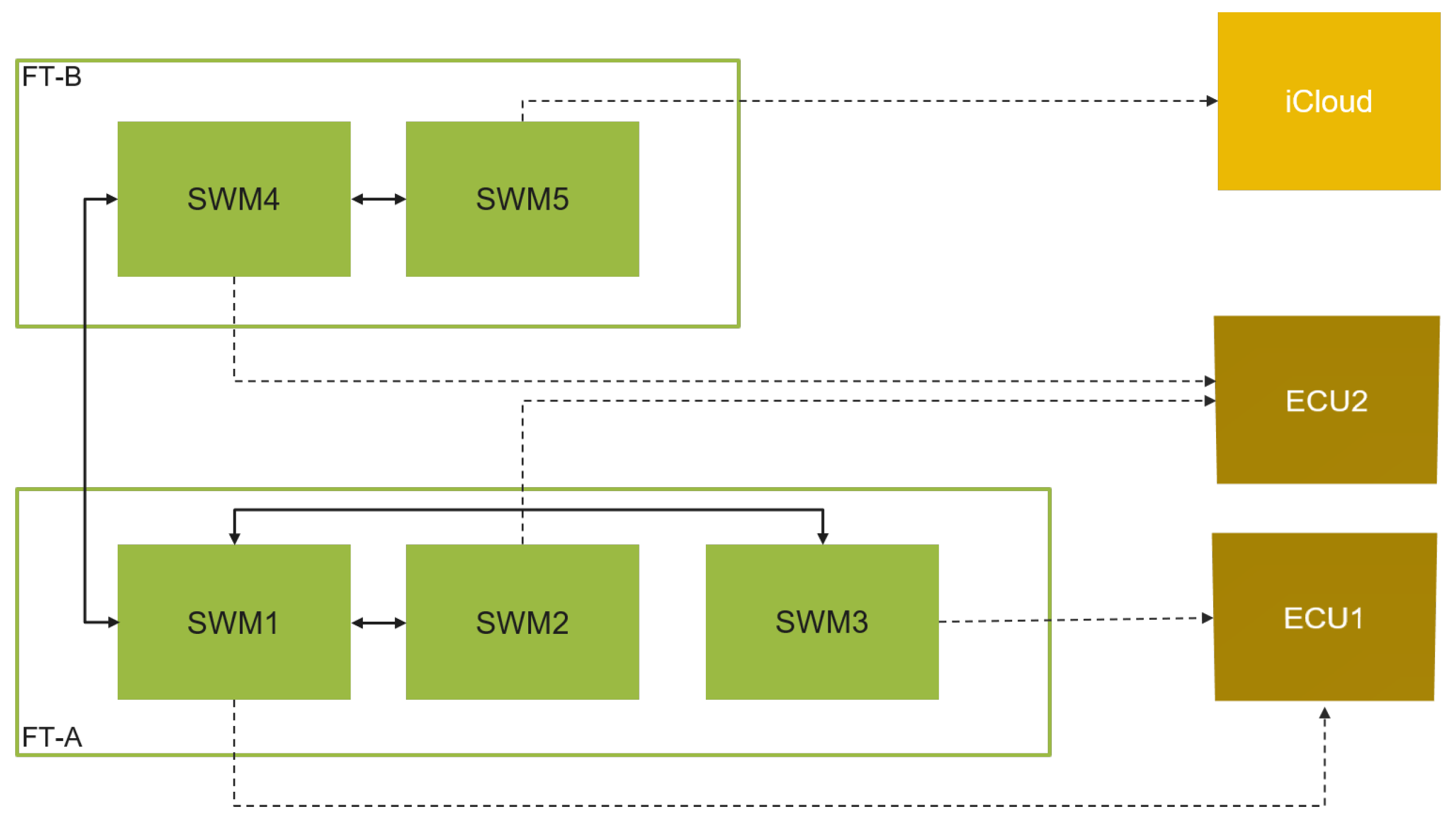
A simple system model example is depicted in Figure 8. The system is composed of five software modules, SWM1, SWM2, and SWM3 are assigned to logical subsystem (e.g., feature set) FT-A, and SWM4 and SWM5 are assigned to subsystem FT-B. The software modules SWM1 through SWM4 are deployed to ECU1 and ECU2 in the vehicle, while SWM5 is deployed to an iCloud server. The system has different possible combinations of software module coupling:
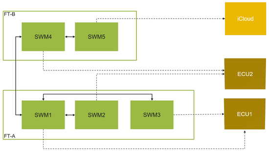
Figure 8.
Deployment of software modules into ECUs and iCloud.
- SWM1 and SWM2 are tightly coupled and reside in different ECUs;
- SWM1 and SWM3 are tightly coupled and reside in the same ECU;
- SWM1 and SWM4 are coupled and reside in different ECUs and different subsystems;
- SWM4 and SWM5 are tightly coupled and reside in an ECU and iCloud;
- Other SWM combinations (e.g., SWM2 and SWM3) are not coupled and reside in different ECUs.
When new features are added or existing features undergo architectural changes, it is more likely that functionalities may scatter across multiple various software modules and ECUs. Improper updates may lead to significant vehicle failures. Thus, to identify the potential risks caused by the update of a software module, the complexity and coupling metrics should be applied to software systems. The complexity of one module and the overall complexity of a system have been studied by many researchers. Among the various methods of representing the relationships between different system modules are the dependency structure matrix (DSM) and complexity structure matrix (CSM) [29]. DSM shows only if there is a relationship between two modules in the system, without any additional quantitative and/or qualitative information. CSM preserves the module hierarchy, and it is capable of showing inter- and intramodule dependencies in a visible way. Package coupling metrics [30] can also be used to calculate the coupling between two subsystems based on the information exchanged between their modules.
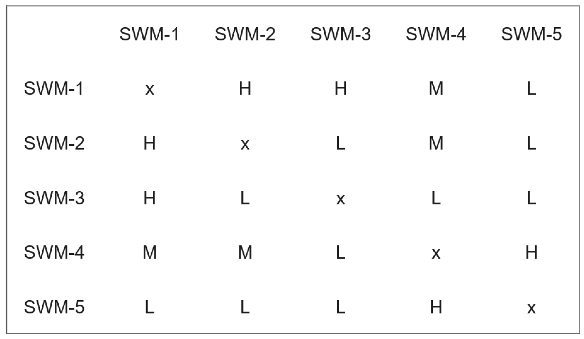
Once the metrics have been defined and their weights have been determined for each software module, the dependency structure matrix analysis can be conducted, and the results guide how the software modules can be allocated to multiple trees. An example of a dependency structure matrix analysis is illustrated in Figure 9. Such a simplified dependency metric gives an opportunity to predict the cost and effort needed to update a software module in the vehicle and also to predict the complexity of the architecture. The more the dependency is, the higher the cost is to update the software module. By utilizing the cohesion and coupling metrics of automotive software modules, early design decisions can be made regarding the creation of multiple trees, and the verification and evaluation of deployment can be improved. Consequently, the subtrees are reorganized so that software modules with closer dependencies are grouped together within a single subtree.

Figure 9.
Example of dependency structure matrix analysis used to design the Merkle tree.
6. Experimental Evaluation
The software architecture may vary in scale depending on the OEM. Thus, different levels for the system and different scenarios are targeted in this environment since metrics are rarely fully validated until they have been tried and tested under many conditions. As explained in the previous section, a software module is considered coupled to another one if it invokes the other’s services or data or complement each other to meet a functionality. In our tests, the analysis for our approach was independent of the applied OEM software architectures and without detailed focus on the software modules themselves. The update of software modules was analyzed to highlight the impact of the interdependence or connectivity between the software modules through the break down of a single tree into multiple trees.Then, the impact of the Merkle tree design was evaluated by studying the costs of communication and computation of updating the software module based on the tree size in our study.
The performance of our concept was assessed through experiments and compared to that of the single-tree-based SOTA process. The test target ECU used an Infineon AURIX™ starter kit triboard with a TC49x 32-bit microcontroller [31]. The microcontroller operated at a 400 MHz CPU clock and was connected to a laptop, acting as the repository via a UART/USB interface. To securely implement our concept in the ECU, the hardware security engines were utilized for hash calculations and signature verification operations. Our study employed the SHA2-256 hash algorithm. The choice of different hash algorithms does not significantly affect execution timing, as the hashing computation was executed with the AURIX ™ hardware security module (HSM). The programming tools, such as Infineon MemTool [32], were used to simplify the process of flashing a new image onto the evaluation board. Cryptographic key setup was beyond the scope of this study, and keys were loaded onto the device using programming tools.
The main parameters of our test setup were as follows:
- N is the number of software modules in the system.
- SW = SW1, …, SWN: SWi is one of the software modules to be updated in an ECU.
- MT is the Merkle tree structure, and MT[x][y] is the node at height x and index y.
- M is the number of subtrees in the system.
- MTs = MTs1, …, MTsM: MTsj is one of the subtrees in the system,
- N = N1 + …+ NM: Nj is the number of the software modules in subtree MTsj.
- Hi is the hash value of the software cluster SWi image, and ‖Hi‖ is the size of Hi in bytes.
- HT is the Merkle tree height. The height at the root node is equal to log2(N).
- HTs is the Merkle subtree height. The height at the root node is equal to log2(Nj).
The communication cost associated with software module updates in vehicles is directly proportional to the amount of data that must be transmitted from the repository to the ECU within the vehicle. This data covers the software image, the signature, and the SVAI (Supplementary Vehicle Authentication Information). In a Merkle tree with N leaves, the SVAI data includes log2(N) nodes. Therefore, the higher the tree, the longer the proof path is. In addition to the node, the ECU needs to know additional information about the location of the node and transmitted SVAI elements. In other words, SVAI data is reduced by one node element every time the tree height is reduced by 1. By using a binary balanced Merkle tree and SHA2-256 as a hash algorithm, our test setup will save 32 bytes of transferred data for each software module update if a tree is divided into 2 subtrees, 64 bytes if it is divided into 4 subtrees, and bytes if it is divided into x subtrees. Figure 10 shows the size of the SVAI transferred to verify a software module. Dividing a Merkle tree of 512 nodes (9 as height) into 8 trees of 64 nodes each, the transferred SVAI is reduced from 288 to 192 bytes.
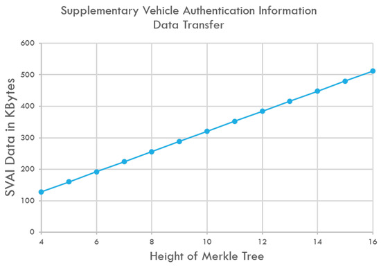
Figure 10.
As the Merkle tree grows in size, the transferred SVAI data also increase. The quantity of SVAI is directly linked to the tree’s height, and with each increment in height, an extra element is transferred.
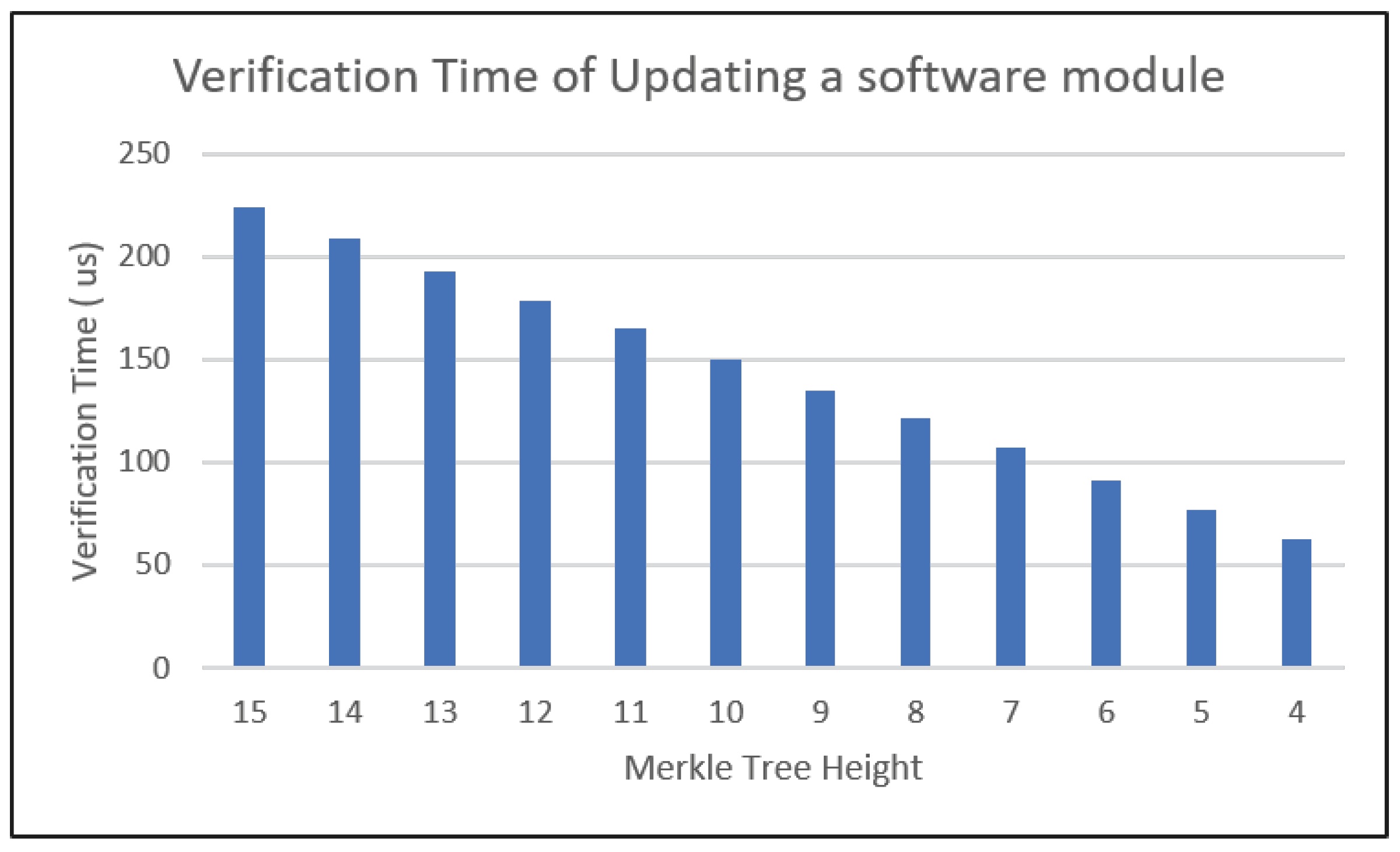
The computation cost for each software module is directly linked to the number of hash values that must be generated within the ECU, as well as the size of the block to be hashed. As the number of hash values increases, the computational expense required to process the data grows proportionally. This correlation arises because as the Merkle tree expands in size, the number of hash computations needed to calculate the root hash value of the tree increases, resulting in faster processing times and less demand for computational resources. Each node element that is transferred within the SVAI results in a hash operation within the ECU. Figure 11 shows the reduction in the verification time of updating a software module with regard to the Merkle tree height. For instance, for a Merkle tree with a height of 15 is divided into multiple subtrees, such as being decomposed into four trees, the time required to verify a software module can be reduced by 31 microseconds. Furthermore, decomposing it into 32 trees reduces the verification time by 74 microseconds for each software module update.
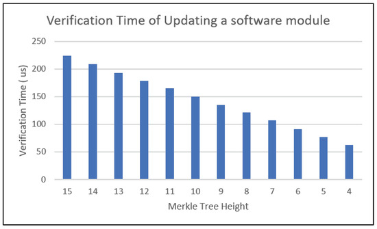
Figure 11.
The verification time for updating a software module decreases as the height of the Merkle tree decreases.
Such results highlight the significance of feature categorization and metric attributes, primarily defined by OEMs. The more thorough and well planned the design of the Merkle subtrees, the more efficient the communication and computation costs for software module updates. This indicates that a thoughtful and thorough approach to designing the Merkle subtree can lead to improvements in computational efficiency, ultimately enhancing the performance of the software module update process.
7. Conclusions
In conclusion, this paper presented the expanding MT-SOTA concept to cover the solution space of feature-based product line engineering, which subsequently introduced a methodology for customizing the software update process. The concept of coupling and cohesion between software modules is addressed for the design and development of the Merkle tree, which forms the foundation of the MT-SOTA approach. The method can assist OEMs in managing software complexity, streamlining the implementation of MT-SOTA vehicle updates, and asserting control over the features and functions of their entire vehicle product lines. An experiment was carried out to illustrate how the performance of software updates can improve through the effective implementation of methods and strategies for analyzing dependency metrics in the design of Merkle trees, resulting in the decomposition of a large tree into multiple smaller trees. Each OEM can adapt and implement the proposed integration of PLE and MT-SOTA through their own respective contexts, driven by their distinct architectures and constraints. Further research can be conducted to analyze diverse real scenarios from various OEMs to accommodate different architectures, as well as to assess the impact of the multiple trees on the OEM repositories. Automotive software architecture addresses the intersection of OEMs’ business goals, user goals, and technical ECU capabilities and resources. OEMs must assess current feature-based design and focus on building software models based on their desired architecture and automotive-specific needs for safety, security, flexibility, and resource efficiency. This study represents a first theoretical step toward achieving this objective.
8. Patents
There is a pending patent related to the work reported in this manuscript.
Author Contributions
Writing—original draft preparation, A.B.; Supervision, A.S. and D.M. All authors have read and agreed to the published version of the manuscript.
Funding
This research received no external funding.
Institutional Review Board Statement
Not applicable.
Informed Consent Statement
Not applicable.
Data Availability Statement
Data are contained within the article.
Acknowledgments
We would like to thank the anonymous reviewers for their review of this paper.
Conflicts of Interest
The authors declare the following financial interests/personal relationships that may be considered as potential competing interests: Abir Bazzi is currently employed by Infineon Technologies. The evaluation platform used for the experiments is provided by Infineon. However, the author has taken the necessary precautions to generalize the results as much as possible.
Abbreviations
The following abbreviations are used in this manuscript:
| ADAS | Advanced driver assistance system |
| E/E | Electrical/electronic |
| ECU | Electronic control unit |
| ImgR | Image repository |
| MT-SOTA | Merkle-tree-based software updates over the air |
| OEM | Original equipment manufacturer |
| OemR | OEM repository |
| OtaM | OTA master |
| PLE | Product line engineering |
| SOA | Service-oriented architecture |
| SOTA | Software updates over the air |
| SVAI | Supplementary vehicle authentication information |
References
- The Future of Automotive Computing: Cloud and Edge, In McKinsey & Company. Available online: https://www.mckinsey.com/industries/semiconductors/our-insights/the-future-of-automotive-computing-cloud-and-edge (accessed on 1 April 2024).
- Bazzi, A.; Shaout, A.; Ma, D. MT-SOTA: A Merkle-Tree-Based Approach for Secure Software Updates over the Air in Automotive Systems. Appl. Sci. 2023, 13, 9397. [Google Scholar] [CrossRef]
- Bazzi, A.; Shaout, A.; Ma, D. A Novel Variability-Rich Scheme for Software Updates of Automotive Systems. IEEE Access 2024, 12, 79530–79548. [Google Scholar] [CrossRef]
- Dixon, R. Evolution of New EE Architecture, S&P Global. Available online: https://autotechinsight.ihsmarkit.com/shop/product/5003328/evolution-of-new-ee-architecture-october-2022 (accessed on 10 January 2024).
- Liu, B.; Betancourt, V.; Zhu, Y.; Becker, J. Towards an On-Demand Redundancy Concept for Autonomous Vehicle Functions using Microservice Architecture. In Proceedings of the IEEE International Symposium on Systems Engineering (ISSE), Virtual Conference, 12 October–12 November 2020; pp. 1–5. [Google Scholar]
- Lotz, J.; Vogelsang, A.; Benderius, O.; Berger, C. Microservice Architectures for Advanced Driver Assistance Systems: A Case-Study. In Proceedings of the IEEE International Conference on Software Architecture Companion (ICSA-C), Hamburg, Germany, 25–25 March 2019; pp. 45–52. [Google Scholar]
- Obergfell, P.; Kugele, S.; Sax, E. Model-Based Resource Analysis and Synthesis of Service-Oriented Automotive Software Architectures. In Proceedings of the ACM/IEEE 22nd International Conference on Model Driven Engineering Languages and Systems (MODELS), Munich, Germany, 15–20 September 2019; pp. 128–138. [Google Scholar]
- Berger, C.; Nguyen, B.; Benderius, O. Containerized Development and Microservices for Self-Driving Vehicles: Experiences & Best Practices. In Proceedings of the IEEE International Conference on Software Architecture Workshops (ICSAW), Gothenburg, Sweden, 5–7 April 2017; pp. 7–12. [Google Scholar]
- Becker, M.; Zhonghai, L.; Chen, D.-J. Towards QoS-Aware Service-Oriented Communication in E/E Automotive Architectures. In Proceedings of the 44th Annual Conference of the IEEE Industrial Electronics Society, Washington, DC, USA, 21–23 October 2018; pp. 4096–4101. [Google Scholar]
- AUTOSAR. Adaptive Release R23-11. 2023. Available online: https://www.autosar.org/search?tx_solr%5Bfilter%5D%5B0%5D=category%3AR23-11&tx_solr%5Bfilter%5D%5B1%5D=platform%3AAP&tx_solr%5Bq%5D= (accessed on 1 May 2024).
- Stellantis Presents Its Software Strategy, Stellantis. Available online: https://www.stellantis.com/content/dam/stellantis-corporate/investors/events/stellantis-sw-day/Software_Day_2021_Presentation_final.pdf (accessed on 1 August 2024).
- Dahad, N. Mercedes-Benz Shows OS Central to Delivery of Future Software-Driven Cars. Available online: https://www.embedded.com/mercedes-benz-shows-os-central-to-delivery-of-future-software-driven-cars/ (accessed on 1 August 2024).
- Virtual SDV Symposium. 2023. Available online: http://www.vector.com/sdv-symposium/ (accessed on 1 August 2024).
- Bass, L.; Weber, I.; Zhu, L. DevOps: A Software Architect’s Perspective; Addison-Wesley Professional: London, UK, 2015. [Google Scholar]
- Kang, K.C.; Lee, J.; Donohoe, P. Feature-oriented product line engineering. IEEE Softw. 2002, 19, 58–65. [Google Scholar] [CrossRef]
- Apel, S.; Batory, D.; Kästner, C.; Saake, G. Feature-Oriented Software Product Lines; Springer: Berlin/Heidelberg, Germany, 2013. [Google Scholar]
- Kuppusamy, T.K.; DeLong, L.A.; Cappos, J. Uptane: Security and Customizability of Software Updates for Vehicles. IEEE Veh. Technol. Mag. 2018, 13, 66–73. [Google Scholar] [CrossRef]
- Steger, M.; Boano, C.A.; Niedermayr, T.; Karner, M.; Hillebrand, J.; Roemer, K.; Rom, W. An Efficient and Secure Automotive Wireless Software Update Framework. IEEE Trans. Ind. Informatics 2018, 14, 2181–2193. [Google Scholar] [CrossRef]
- Ghosal, A.; Halder, S.; Conti, M. STRIDE: Scalable and Secure Over-The-Air Software Update Scheme for Autonomous Vehicles. In Proceedings of the IEEE International Conference on Communications (ICC), Dublin, Ireland, 7–11 June 2020; pp. 1–6. [Google Scholar]
- Mansour, K.; Farag, W.; ElHelw, M. AiroDiag: A sophisticated tool that diagnoses and updates vehicles software over air. In Proceedings of the IEEE International Electric Vehicle Conference, Greenville, SC, USA, 4–8 March 2012; pp. 1–7. [Google Scholar]
- Mayilsamy, K.; Ramachandran, N.; Raj, V.S. An integrated approach for data security in vehicle diagnostics over internet protocol and software update over the air. Sci. Direct-Comput. Electr. Eng. 2018, 7, 578–593. [Google Scholar] [CrossRef]
- Suzuki, N.; Hayashi, T.; Kiyohara, R. Data Compression for Software Updating of ECUs. In Proceedings of the IEEE 23rd International Symposium on Consumer Technologies, Ancona, Italy, 19–21 June 2019; pp. 304–307. [Google Scholar]
- Bogdan, D.; Bogdan, R.; Popa, M. Delta flashing of an ECU in the automotive industry. In Proceedings of the IEEE 11th International Symposium on Applied Computational Intelligence and Informatics, Timisoara, Romania, 12–14 May 2016; pp. 503–508. [Google Scholar]
- NIST FIPS 186-4; Digital Signature Standard (DSS). U.S. National Institute of Standards and Technology: Gaithersburg, MD, USA, 3 February 2023.
- AUTOSAR CP R23-11; Explanation of Application Interfaces of the Chassis Domain. Classic Platform Release R23-11. 2023. Available online: https://www.autosar.org/fileadmin/standards/R23-11/CP/AUTOSAR_CP_EXP_AIChassis.pdf (accessed on 1 August 2024).
- IEEE Std 1471-2000; IEEE Recommended Practice for Architectural Description for Software-Intensive Systems. The Institute of Electrical and Electronics Engineers, Inc.: New York, NY, USA, 2000; pp. 1–29.
- Fenton, N.; Bieman, J. Software Metrics: A Rigorous and Practical Approach, 3rd ed.; CRC Press, Inc.: Boca Raton, FL, USA, 2014. [Google Scholar]
- Bushong, V.; Abdelfattah, A.S.; Maruf, A.A.; Das, D.; Lehman, A.; Jaroszewski, E.; Coffey, M.; Cerny, T.; Frajtak, K.; Tisnovsky, P.; et al. On Microservice Analysis and Architecture Evolution: A Systematic Mapping Study. Appl. Sci. 2021, 11, 7856. [Google Scholar] [CrossRef]
- Durisic, D.; Staron, M.; Nilsson, M. Measuring the size of changes in automotive software systems and their impact on product quality. In Proceedings of the 12th International Conference on Product Focused Software Development and Process Improvement (Profes ’11), Torre Canne Brindisi, Italy, 20–22 June 2011; Association for Computing Machinery: New York, NY, USA, 2011; pp. 10–13. [Google Scholar]
- Gupta, V.; Chhabra, J.K. Package Coupling Measurement in Object-Oriented Software. Comput. Sci. Technol. 2009, 24, 273–283. [Google Scholar] [CrossRef]
- Infineon Technologies TC4xx Evaluation Board. Available online: https://www.infineon.com/cms/en/product/microcontroller/32-bit-tricore-microcontroller/32-bit-tricore-aurix-tc4x/ (accessed on 20 April 2024).
- Infineon MemTool on-chip Flash Programming. Available online: https://www.infineon.com/cms/en/tools/aurix-tools/free-tools/infineon/ (accessed on 20 April 2024).


Disclaimer/Publisher’s Note: The statements, opinions and data contained in all publications are solely those of the individual author(s) and contributor(s) and not of MDPI and/or the editor(s). MDPI and/or the editor(s) disclaim responsibility for any injury to people or property resulting from any ideas, methods, instructions or products referred to in the content. |
© 2024 by the authors. Licensee MDPI, Basel, Switzerland. This article is an open access article distributed under the terms and conditions of the Creative Commons Attribution (CC BY) license (https://creativecommons.org/licenses/by/4.0/).