Article

Recovery of Magnetic Particles from Wastewater Formed through the Treatment of New Polycrystalline Diamond Blanks

1
IME Process Metallurgy and Metal Recycling, RWTH Aachen University, D-52056 Aachen, Germany
2
Redies Deutschland GmbH, Metzgerstr. 1, D-52070 Aachen, Germany
3
Faculty of Technology and Metallurgy, University of Belgrade, Karnegijeva 4, 11000 Belgrade, Serbia
4
Department of Materials Science and Engineering, Norwegian University of Science and Technology, 8900, NO-7491 Trondheim, Norway
5
Faculty of Technology, University of East Sarajevo, Karakaj 34 A, 75400 Zvornik, Bosnia and Herzegovina
*
Author to whom correspondence should be addressed.
Waste 2023, 1(4), 993-1006; https://doi.org/10.3390/waste1040057
Submission received: 1 November 2023 / Revised: 26 November 2023 / Accepted: 5 December 2023 / Published: 8 December 2023

Abstract

:
Cobalt’s pivotal role in global development, especially in lithium-ion batteries, entails driving increased demand and strengthening global trading networks. The production of different waste solutions in metallurgical operations requires the development of an environmentally friendly research strategy. The ultrasonic spray pyrolysis and hydrogen reduction method were chosen to produce nanosized magnetic powders from waste solution based on iron and cobalt obtained during the purification process of used polycrystalline diamond blanks. With specific objectives focused on investigating the impact of reaction temperature and residence time on the morphology, chemical composition, and crystal structure of synthesized nanosized cobalt powders, our research involved 15 experimental runs using two reactors with varying residence times (7.19 s and 23 s) and distinct precursors (A, B, and C). Aerosol droplets were reduced at 600 to 900 °C with a flow rate of 3 L/min of argon and hydrogen (1:2). Characterization via scanning electron microscopy (SEM), energy dispersive spectroscopy (EDS), and X-ray diffraction revealed that higher temperatures influenced the spherical particle morphology. Altering cobalt concentration in the solution impacted the particle size, with higher concentrations yielding larger particles. A short residence time (7.9 s) at 900 °C proved optimal for cobalt submicron synthesis, producing spherical particles ranging from 191.1 nm to 1222 nm. This research addresses the environmental significance of recovering magnetic particles from waste solutions, contributing to sustainable nanomaterial applications.

1. Introduction

Cobalt is a strategic metal that plays a central role in global development, particularly due to its increasing importance in lithium-ion batteries and energy storage systems. The growth in global cobalt demand is expected to strengthen international cobalt trading networks. Advances in technology have promoted the application of cobalt in various fields, including catalysts, paints, and alloys critical to the engineering and aerospace industries and significant contributions to the medical field. The increase in cobalt consumption in the rechargeable battery industry coincides with continued global emphasis on energy storage and electrification plans, which are critical to the transition to a low-carbon economy [1,2,3]. Africa, rich in critical minerals such as cobalt, lithium, copper, graphite, nickel, and rare earth minerals, is well-positioned to meet the rising demand in the global electric vehicle (EV) market. The cobalt market rebounded in 2021, primarily driven by lithium-ion battery applications, with a projected growth of 51 kt from 2015 to 2020 [4,5].
The US Environmental Protection Agency has classified cobalt as in the priority list of environmental risk elements as a potentially hazardous pollutant [6]. Cobalt mining poses significant environmental risks, including soil erosion, water contamination, air pollution, and hazardous waste management. The Democratic Republic of the Congo (DRC) accounts for a substantial portion of global cobalt production, raising concerns about the reliability and sustainability of supply chains. Human rights abuses, including child labor and hazardous working conditions, are also associated with cobalt mining in the DRC. The concentration of cobalt production in a few countries and geopolitical tensions create vulnerabilities in the global supply chain, impacting industries reliant on battery technologies. Countries with significant cobalt reserves hold strategic influence in the emerging green energy sector [7,8]. Recycling cobalt from diverse secondary sources is vital for a circular economy, given its critical raw material status and primary supply uncertainty [9].
Cobalt recovery typically comes from primary and secondary materials, with laterite ores being the primary global source, containing 1.3% Ni and 0.04% Co on average [10]. While pyrometallurgy is dominant, hydrometallurgical methods are increasing, offering lower energy and operational costs as well as environmental benefits. A specific process achieved high recovery rates, with over 91% for cobalt and 84% for copper from cobaltite concentrate, using oxidative pressure leaching, jarosite precipitation, ferric arsenic precipitation, selective solvent extraction, and electrowinning [11]. The ultrasonic spray pyrolysis method is a cost-effective and adaptable technique based on an aerosol process for synthesizing nanoparticles and depositing thin films. The technique is capable of synthesizing metal, oxide, and composite nanomaterials with precisely controllable morphologies and chemical compositions using metal salts in aqueous solvents Ultrasonic spray pyrolysis produces ultrafine nanoparticles from solution. The equipment includes an ultrasonic spray zone connecting the heating zone and the collection zone. Ultrasonic spray is an aerosol-generating system with an ultrasonic atomizer and a droplet-carrying system with a gas carrier [12,13].
Chandra et al. [9] found that H2SO4 acid leaching is efficient for cobalt and molybdenum, favoring solvent extraction or precipitation for metal recovery. Pyrometallurgical processes encompass calcination smelting while pyro-hydrometallurgical methods involve alkali roasting and chlorination roasting combined with leaching. Biohydrometallurgical processes with microorganisms like Acidithiobacillus ferrooxidans and Acidithiobacillus thiooxidans explore cobalt leaching from spent catalysts.
Sivasakti et al. [14] recovered cobalt from a waste catalyst by using roasting and a hydrometallurgical system involving sulfuric acid leaching and precipitation. The resulting cobalt sulfate solution was electrolytically recovered, yielding a 70% cobalt content metallic deposit. Similarly, Wolanczyk et al. [15] employed a fou-stage process to efficiently recover cobalt (II) from the solution after leaching spent industrial catalysts, ensuring successful leaching, impurity removal, and effective Co(II) separation from Mo(VI).
A novel hydrometallurgical process recovers pure cobalt sulfate from waste catholic material in lithium-ion battery manufacturing [16]. Leaching achieved 93% cobalt and 94% lithium extraction. Solvent extraction resulted in 85.42% cobalt recovery. The remaining cobalt was fully recovered and a 99.99% pure cobalt sulfate solution was obtained via H2SO4 stripping.
Although a lot of work has been conducted for the recovery of magnetic particles, USP-HR remains underexplored in cobalt production; there is also a gap in understanding the synergetic effect of USP and hydrogen reduction on cobalt powder characteristics and application. Addressing current challenges in cobalt requires an exploration of more eco-friendly methods with the ultimate goal of achieving high-purity cobalt powder. In this particular study, the synthesis of cobalt powder from industrial waste solutions derived from the leaching process of industrial polycrystalline diamond blanks of the wire dies industry (Redies Deutschland GmbH) was conducted. The synthesis process involved employing ultrasonic spray pyrolysis (USP) [12,13,14,15,16] and hydrogen reduction methods within a temperature range of 600 to 950 °C.
The primary aim of this study was to recover cobalt and iron from these waste solutions producing magnetic nanoparticles developing one combined research strategy from ultrasonic spray pyrolysis and hydrogen reduction. Specifically, the objectives of this work consist of using scanning electron microscopy (SEM), energy dispersive X-ray spectroscopy (EDS), and X-ray diffraction (XRD) analysis to examine how reaction temperature and residence time impact the characteristics of final particles.

2. Experimental

2.1. Electrochemical Analysis of Cobalt and Iron in Nitrate Solution

Before the experimental work, thermochemical analysis was performed using Software FactSage, version 6.4. The Pourbaix diagram (E-pH) of iron-cobalt nitrate in water solution at room temperature shows the presence of iron and cobalt in solid form Co3O4 and Fe2O3, and ionic form Co2+ and Fe2+ in the pH area below two (acidic system). Figure 1, below, shows that with an increased potential between 0.67 and 1.8 V, cobalt is available in the form of ion Co2+ and solid Co3O4; iron is available only in the form of solid Fe2O3.
The performed analysis has confirmed that it is very difficult to separate iron and cobalt ions from the liquid phase. The use of solvent extraction is needed to dissolve these elements.
The electrochemical properties of cobalt(II), nickel(II), and iron(II) ions were investigated through cyclic voltammetry in a study conducted by [17]. The results demonstrate that the introduction of small quantities of 2,2′-bipyridine (bpy), ranging from 10% to 50% mol, into solutions containing cobalt(II), nickel(II), and iron(II) ions contributes to the stabilization of their reduced metal(0) forms. This stabilization effectively inhibits both the electrochemical deposition of these metals and the formation of insoluble metal associates.

2.2. Materials

Without any purification, the industrial waste solution from the leaching process of polycrystalline diamond blank with a grain size of 5 μm was used as the starting material for this research, as shown at Figure 2 (for more details, see the ref. [18]). The term polycrystalline diamond (PCD) summarizes a variety of amorphous compounds mostly or wholly consisting of microscopically small diamond grains. A single crystal of natural diamond is anisotropic regarding mechanical and thermodynamic properties including tensile strength and thermal conductivity for instance, as shown in Figure 3.
Most PCD will have a random arrangement of the individual grains resulting in a quasi-isotropic compound, as shown in Figure 3.
However, there are forms of PCD that are made differently and have different properties. The company REDIES Deutschland GmbH, Aachen, Germany, produces wire drawing tools made from diamond materials. Therefore, their recovery is from high importance.

2.3. Methods

2.3.1. Preparation of Waste Solution from PCD

Before starting the purification experiment, some steps of preparation were necessary. The setup had to be cleaned to avoid contaminations. The seals’ and joints’ gas tightness had to be checked as well as the ventilation and power supplies in the fume hood. Before the experimental runs in weeks 3 and 6, rust had to be removed from the steel stands and drill chucks to avoid rust flakes falling into the ultrasound baths. All glass vessels (Fischer Scientific, Langerwehe, Germany), whether they were situated in the reactor, beaker, or flask, were cleaned the same way. First, the remaining high viscosity lubricant was wiped off with paper towels. Then, the vessels were rinsed and scrubbed using Sodosil™ (Sodasil, Sigma-Aldrich, Darmstadt, Germany) and hot tap water. After rinsing the glassware thoroughly with distilled water, a small amount of ethanol was used to accelerate drying. This procedure was also applied to sampling equipment during the experiments. The two gas washers with NaOH, 1M, were prepared by dissolving 28 g of solid NaOH pearls in 700 mL of distilled water for each bottle. Of course, checking the gas tightness of tubes and hoses in the Argon line and behind both reactors was also part of the routine.
The PCD blanks were weighed and measured with the Tesla meter beforehand to obtain the important 100% reference value for evaluation. The fixed volume of nitric acid was prepared in covered beakers for each reactor [18]. Since there was very little time between mixing the two liquids and the beginning of gas formation, if any, measuring the acids consecutively was not an option. Meanwhile, the ultrasound baths had been filled with tap water and their heaters were set to 60 °C and 80 °C, respectively, to ensure that the bath temperature was nominal at the beginning of the experiment. Except for the ninth and last week, the aqua regia was also pre-heated before adding the PCD to have nominal conditions right from the start. In week nine, the opportunity to take pictures of the color changes of the solution was not to be missed. As a consequence, the nitric acid in reactor 2 was not heated the same way before adding PCD. There is no indication of a negative effect in the results, probably due to the overall very long run time of the experiments.
After finishing the preparational work, there were parts of the procedure to be repeated daily, one of which was taking samples of the liquids and PCD blanks. The first step when entering the laboratory each day was to check if the ventilation of the room and its fume hood were still working. Then, a quick visual and olfactory check of the apparatus was made to ensure gas tightness and good function of the stirrers, as shown in Figure 4.
The need for this caution became clear when a stirrer seal became caught on the stirrer and loosened itself from the glass joint in the first week. In week 8, the rubber tube on the argon inlet slipped off the coupler, eliminating gas flow and allowing unfiltered acidic NOx-containing fumes into the fume cabinet; fortunately, this lasted only for a short period.
In weeks 1 through to 3, the ultrasound baths were only used as heated water baths. In weeks 4–6, the ultrasound was intended to be switched on for eight hours per day. Thus, in addition to refilling water, the time of ultrasound irradiation also had to be noted. In the remaining three weeks, the ultrasound was switched on permanently.
To sample PCDs and solution, the reactors had to be opened. For liquid samples only, the inlet gas coupler had to be opened. Measuring the PCD after the purification step with nitric acid, however, required more steps. First, the drill chuck was opened to loosen the stirrer. Then, the lab jack with the ultrasound bath was lowered to be followed by the reaction vessel. To make gathering PCD from the round flask easier, the flask was tilted until the stirrer was in a near 45° orientation. Finally, the whole gas inlet was taken off to make the inside accessible.
Upon mixing and pre-heating nitric acid, bubbling brown fumes inside the reactor as well as bubbling in the gas washing bottles indicated gas formation and excess pressure inside the reaction vessels. After one hour of experiment time passed, the pressure inside and outside the reactor had equalized and bubbling in the gas washing bottles had stopped altogether. First, bubbling stopped in reactor 1 and, a few minutes later, reactor 2 showed no more gas flow. Instead, looking closely at the gas washing bottles, the liquid level in the ingoing glass tube rose and fell, indicating fluctuating pressure in the reactors. After about five more minutes, both reactors started sucking the gas-washing solution back into the round flasks and the experiment had to be stopped. A second attempt was made one day later with equally unwanted results so it was decided to install a forced gas flow. A current of around 0.25 L/min was sufficient to ensure the gas flow in one direction only. Argon was chosen over nitrogen or pressured air because oxygen and nitrogen might have skewed the equilibria with NO2 and NxOx or formed combustible mixtures with chlorine gas or hydrogen gas. The color of the solution was changed during purification experiments starting from green, as shown in Figure 4.
For the experimental runs, we prepared three precursors named (A, B, and C) with different concentrations of Fe and Co by dissolving the original precursor in deionized water at different rates (4:1; 2:1; and 1:1), seen in more detail in Table 1.
Experiments were performed in closed reactors in order to avoid contamination and ensure the integrity of the experiment, especially during the preparation of waste solution from PCD. Special attention is taken regarding the use of safety measures in terms of the use of hydrogen for the reduction process, as mentioned in the following chapter.

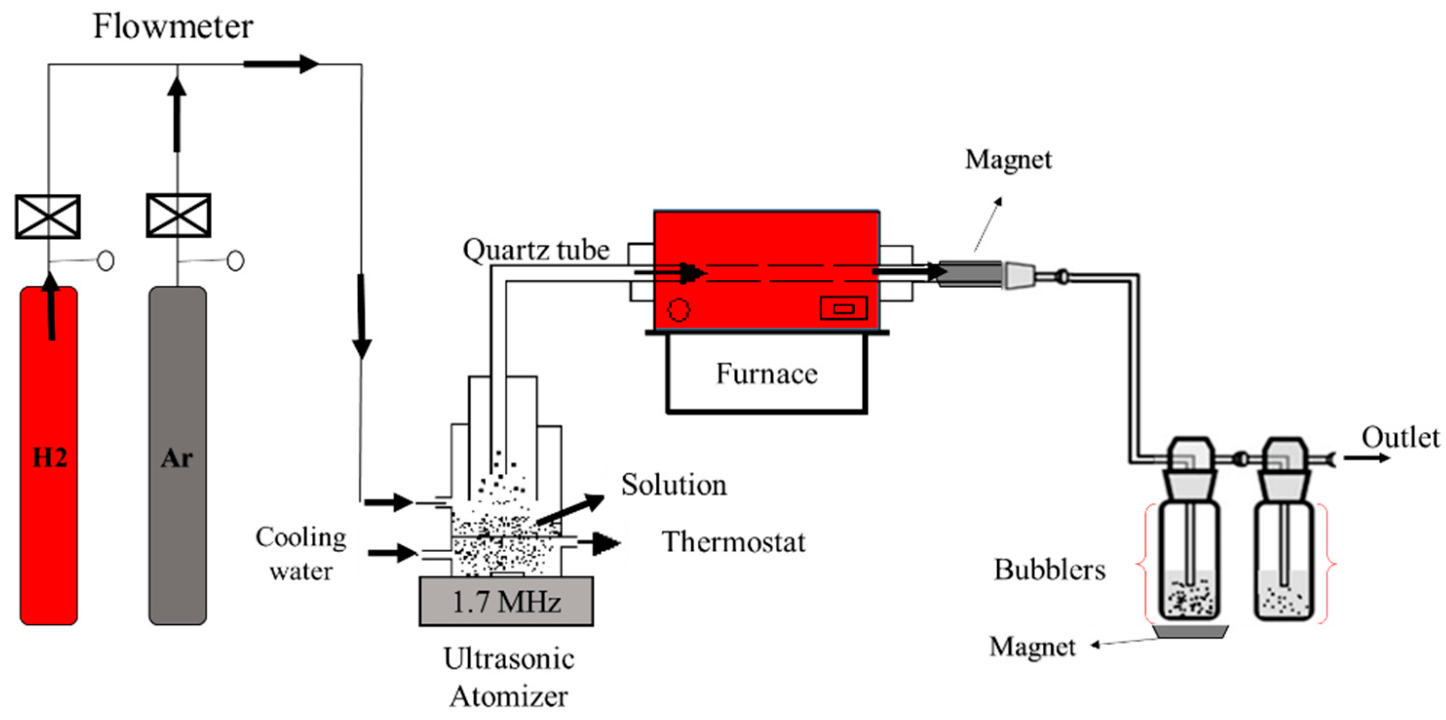
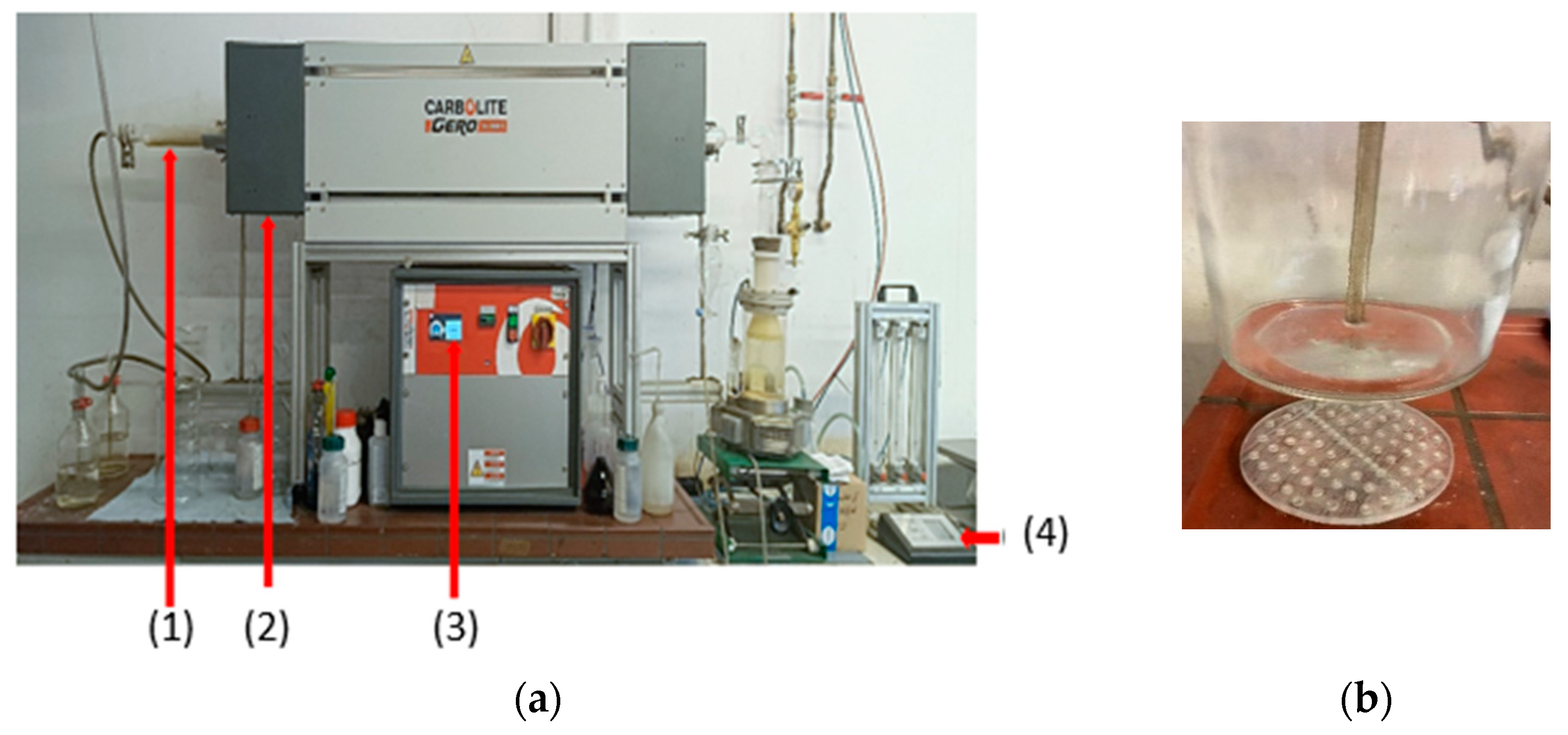
2.3.2. Ultrasonic Spray Pyrolysis Method with Hydrogen Reduction

Fe-Co nanoparticles were synthesized through ultrasonic spray pyrolysis followed by hydrogen reduction. Two setups were employed: a low-temperature setup and a high-temperature setup. The setup consisted of argon and hydrogen bottles, a rotameter, a thermostat, an ultrasonic nebulizer connected to a frequency generator, two wash bottles containing deionized water for collecting nanoparticles, and a gas outlet tube. The typical experimental setup is shown in Figure 5.
The synthesis process begins by setting the oven temperature and then pouring the precursor solution through a funnel into the atomizer. The solution is atomized into droplets at a resonant frequency of 1.7 MHz. The gas mixture delivers liquid droplets into the horizontal tubular reactor. Hydrogen gas with a flow rate of 2 L/min acts as a reducing agent and also carries some liquid droplets into the reactor. Argon gas at a flow rate of 1 L/min facilitated aerosol droplet transport into the reactor and provided an inert atmosphere during hydrogen use. Evaporation, thermal decomposition, and densification of the solvent occured in a 95 cm long quartz tube with an inner diameter of 40 mm. The reduction reaction was carried out at a temperature ranging from 600 to 950 °C for.
Nanoparticles were collected in wash bottles at the reactor outlet. After each experiment, the nanoparticles, suspended in deionized water, were settled in a glass beaker for one day. Subsequently, water removal was attempted using a filter-based collection unit connected to a vacuum pump (Model Ilmvac LVS610 Tp), though not entirely successfully. The nanoparticle suspension was transferred to a small open glass bottle and dried in a vacuum oven at 100 °C to yield powder samples.
The collection of particles using magnets is an innovative idea that can optimize particle collection. The process consisted of placing a magnet on the tube at the exit of the furnace and another magnet under the wash bottle. The magnets were used as an effective tool for minimizing losses by capturing magnetic particles. The strategic placement of magnets aimed to explore the potential of harnessing the magnet’s capability in enhancing particle retention. Further discussion on the outcomes and observations regarding the magnet’s role in reducing losses would contribute to a more comprehensive understanding of our methodology.
Characterization of the obtained particles included X-ray diffraction for phase identification and crystallinity confirmation, scanning electron microscopy (SEM) for morphology analysis, and an energy dispersive spectrometer for compositional analysis.

3. Results and Discussion

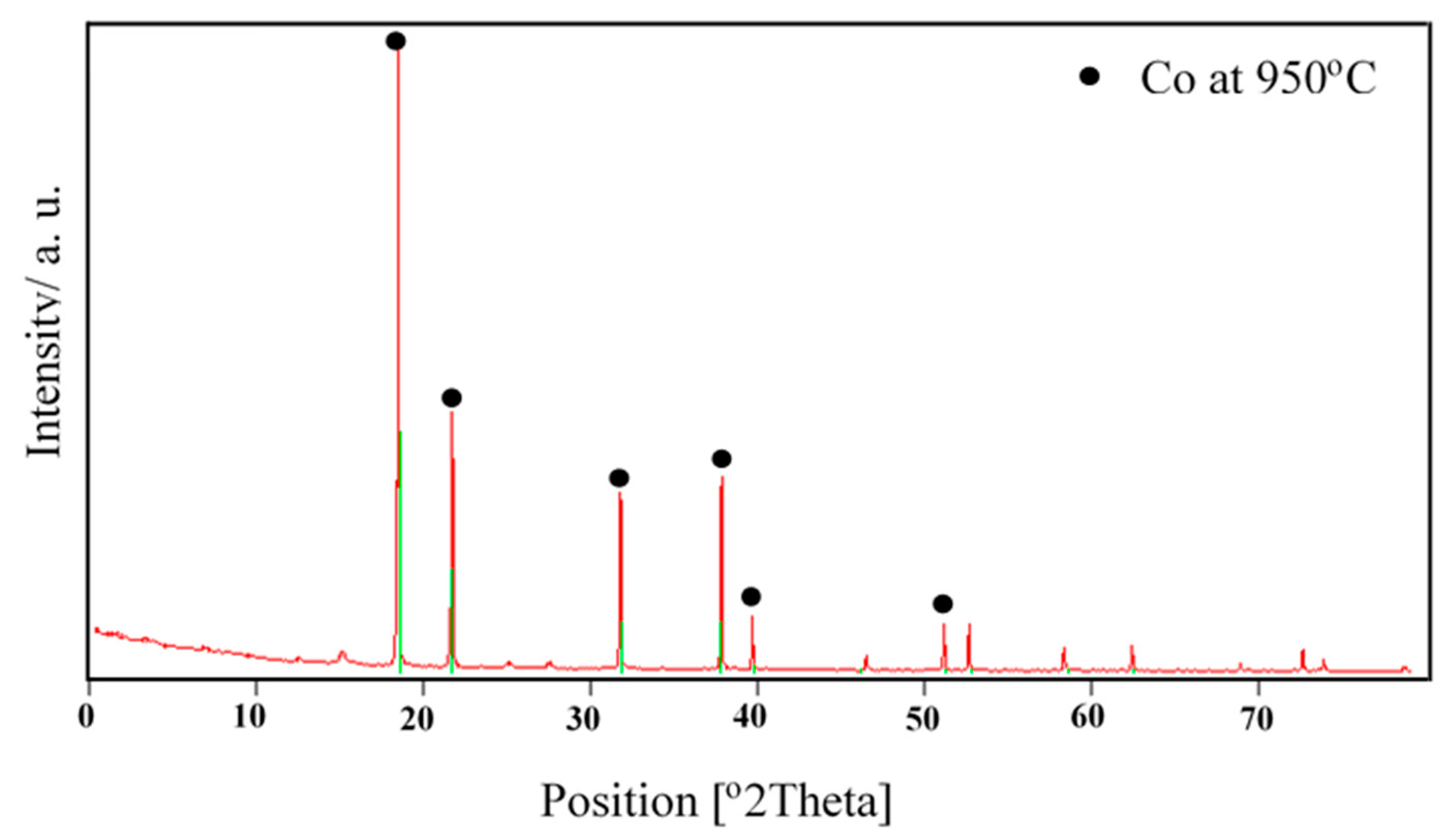
3.1. X-ray Diffraction Analysis

The X-ray diffraction analysis of cobalt powders produced at 950 °C from industrial waste solution using ultrasonic spray pyrolysis and hydrogen reduction is shown in Figure 6. The X-ray diffraction patterns reveal the presence of pure cobalt. It has been reported by [19] that cobalt powders produced at 700, 800, and 900 °C from Co(NO3)2 solution in H2 atmosphere by ultrasonic spray pyrolysis indicated the presence of pure cobalt powders. The previous thermodynamic analysis confirmed the high probability of the formation of Co and Fe from metallic nitrate by hydrogen reduction between 600 °C and 1000 °C. This probability for the formation of Co and Fe increases at elevated temperatures. The expected chemical reactions are presented in Equations (1) and (2):
Co(NO3)2 + H2 = Co + 2 HNO3
Fe(NO3)2 + H2 = Fe + 2 HNO3
A similar study was conducted by [20] on the synthesis of nano-crystalline spherical cobalt–iron (Co–Fe) alloy particles by USP-HR from aqueous cobalt-iron chloride; the temperature ranged up to 1000 °C to confirm the probability for the formation of Co–Fe from CoCl2 + FeCl2 by hydrogen reduction. Although Gibbs free energy is always negative between the 0 and 1200 °C temperature range, it increases through the positive values at elevated temperatures. The body-centered cubic crystalline Co–Fe phase has two main peaks at the diffraction angles of 45° and 65°. The broad hump at the low diffraction angles is coming from the glass substrate which is amorphous. The X-ray analysis of the powders indicated the presence of body-centered cubic crystalline structured Co–Fe (JPDS card no: 03-065-4131) nanoparticles and any diffraction peaks due to oxide phases of Co–Fe were not observed.
A study was conducted by [21] and they found the particles produced by spray pyrolysis at 650, 700, and 750 °C, respectively. The XRD signals at 700 and 750 °C were identified as yttria-stabilized zirconia (YSZ), the tetragonal phase. The XRD signals at 650 °C were less sharp (and therefore, less clearly identified as YSZ); however, after annealing these particles at 800 °C for 30 min, the XRD signals were as sharp as those at 750 °C and, thus, were also identified as YSZ.

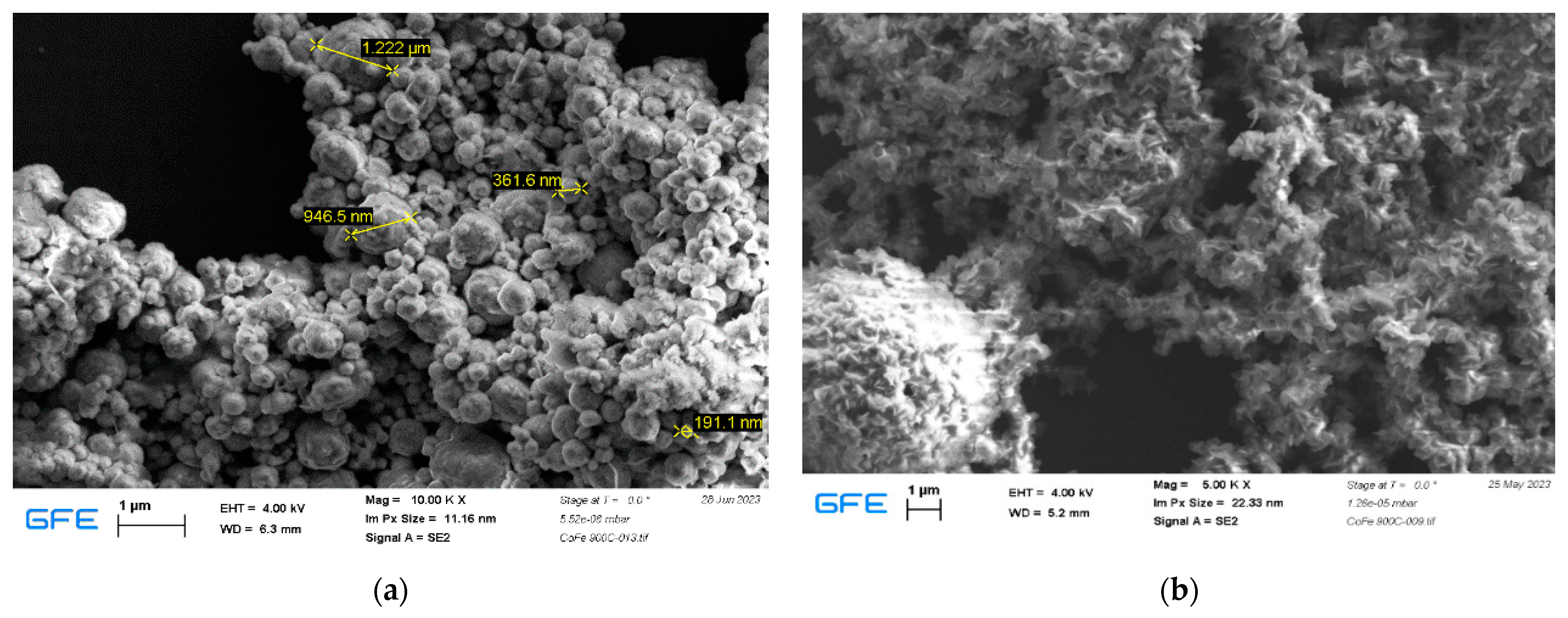
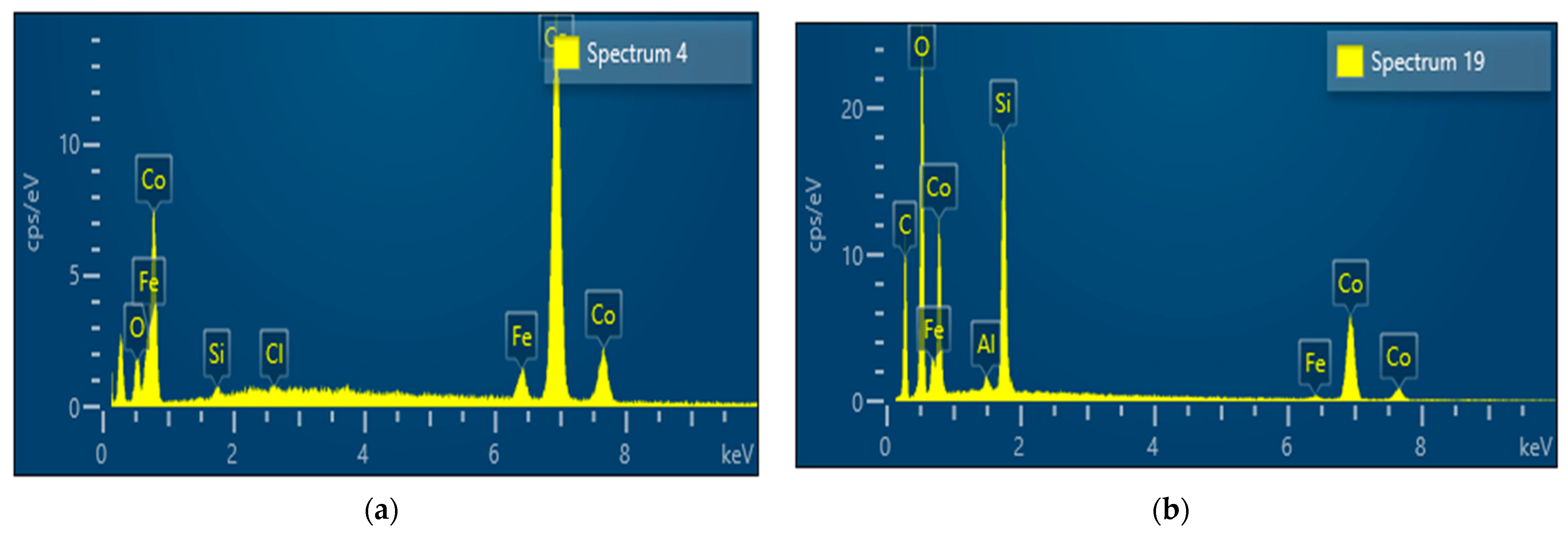
3.2. Influence of the Residence Time

The impact of the residence time on the particle morphology obtained by ultrasonic spray pyrolysis and hydrogen reduction in the solution A at 600 °C and 900 °C is shown in Figure 7. Two furnaces with different residence times were used for 23 s for the larger furnace, as shown in Figure 8 and 7.19 s for the small furnace at room temperature with a gas flow rate of 3 L/min.
SEM reveals the presence of smooth spherical particles with a range of 191.1 nm–1222 nm using the residence time of 7.19 s, as shown in Figure 7a. In Figure 7b, the agglomeration is more pronounced using a long residence time (23 s). From the SEM results, we can assume that the short residence is more favorable for the nanoparticle synthesis of cobalt. By comparing both results we can notice that the residence time in the quartz tube (length: 1.5 m and diameter 0.05 m) is four times larger than one of the small furnaces.
From EDS analysis, we can observe the chemical composition of the obtained particles concerning to short and high residence shown in Figure 9. Table 2 illustrates the quantitative result of chemical component content (weight%) in the obtained particle. Figure 9a reveals a prominent cobalt peak and a small peak of other components like (Si, Cl, Fe, and O) at a short residence time whereas Figure 9b depicts a smaller cobalt peak at a longer residence time. The presence of different elements with strong peaks is observed.
At a short residence time, we observed high cobalt content (92.3 weight%) while we observed a small oxygen content (1.7 weight%) which means the hydrogen reduction process was mostly complete. Looking at the long residence time, the cobalt content was (54.9 weight%) while the oxygen content was (25.8 weight%). From all this information, it is obvious to say the short residence time at high temperatures is favorable to obtained spherical particles with high cobalt content.

3.3. Particle Collection Using Magnets

A new system for the collection of powders was proposed and tested in this study, as shown in Figure 8.
The new system for particle collection has offered the deposition of particles at the bottom of a washing bottle at room temperature without additional heating. As shown in Figure 8b, the particles were collected at the bottom of the bottle. High collection efficiency can be expected using very strong magnets.
SEM analysis was performed on a sample derived from an industrial solution (Solution C) using USP at 950 °C with magnet collection as shown in Figure 10. The result indicated a multimodal distribution of particles. Particle sizes ranged from 0.194 to 1.101 μm, with a mean size of 0.509 μm. The presence of smaller particle sizes in the sample may lead to distinct magnetic, mechanical, and thermal properties, influenced by the precursor concentration, flow rate, and synthesis conditions. The SEM analysis and comparison of particle size distributions offer valuable insights into the material’s characteristics and behavior, relevant to various applications in magnetic, mechanical, and thermal systems, as shown in Figure 10.

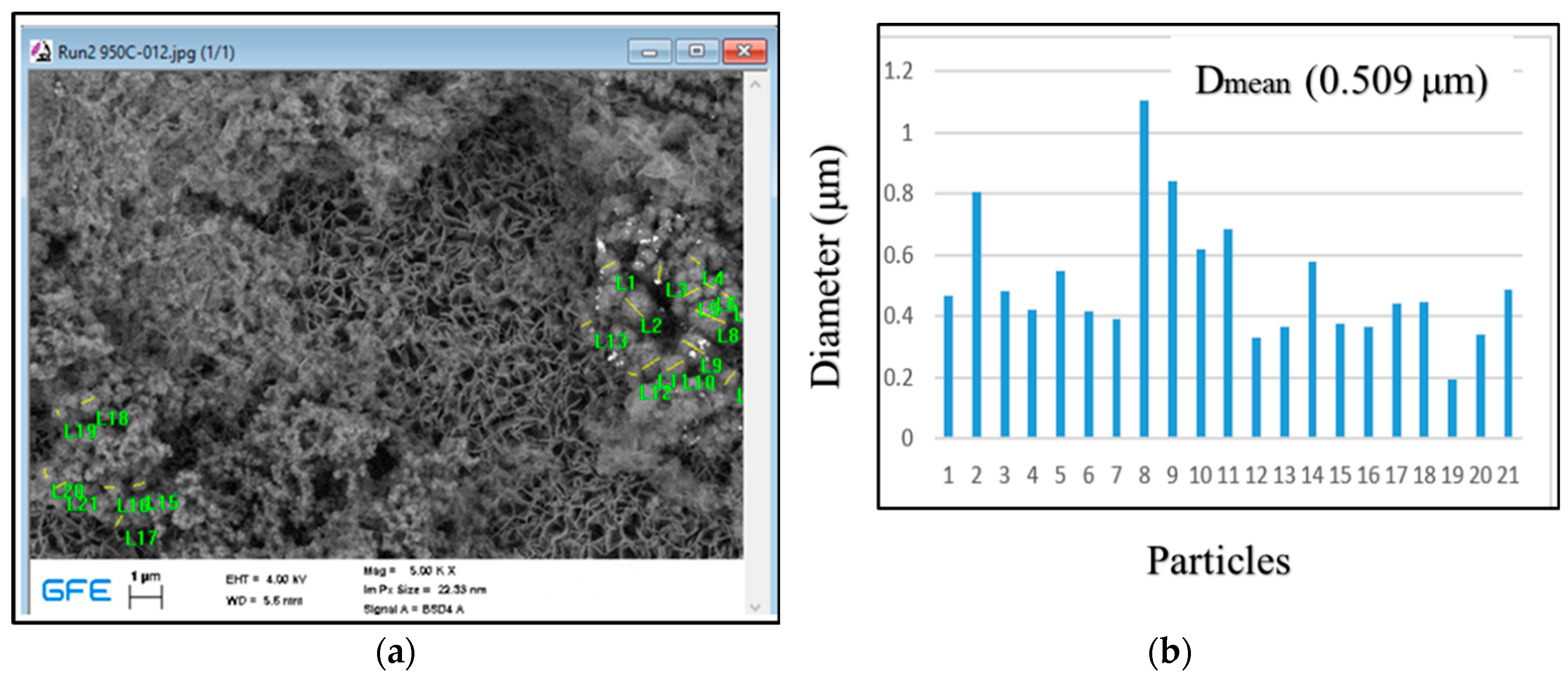
3.4. Influence of the Reaction Temperature

The reaction temperature has a significant effect on the specific surface area, surface morphology, nucleation, and growth of powder particles. Through EDS analysis, the influence of the temperature from 600 °C to 900 °C on the chemical composition of the solution A sample is shown in Table 3. The atomic percentage of Co increases with increasing temperature and the atomic percentage of Fe decreases with increasing temperature. SEM analysis of samples obtained from precursors at different temperatures revealed different distributions of small nanoparticles. The results show the formation of agglomerated spherical Fe-Co particles, crystallographic facets, and spherical agglomerates that are resistant to ultrasonication. Together, these agglomerates form large bulk structures with varying distributions of irregularly shaped small nanoparticles. The changes observed with increasing temperature showed aggregation and irregular shapes of the nanoparticles, ultimately revealing a characteristic layered structure. This means that the elevated temperature is suitable for the synthesis of cobalt, which is in accordance with thermochemical analysis by Gurmen et al. [19,20]. and mentioned results by Tsai et al. [21]. The table shows that the atomic percentage of oxygen decreases slightly with increasing temperature. This increase may be suitable for removing some traces of oxygen, thereby increasing the rate of hydrogen reduction. Silicon and aluminum appear to be temperature resistant; however, Al exhibits a disproportionate change.
In the study of Choa et al. [22], metal/ceramic nanoporous nanocomposite powders were prepared and characterized using ultrasonic spray pyrolysis. The initial material was derived from Fe and Mg nitrates dissolved in pure water. A mist was formed and directed into a preheated chamber (500–800 °C) by an air carrier gas. The results demonstrated that increasing the chamber and reducing temperatures led to larger particle sizes in the Fe/MgO samples. Shatrova et al. [23] investigated on the elaboration, characterization, and magnetic properties of cobalt nanoparticles synthesized by ultrasonic spray pyrolysis followed by hydrogen reduction. They found that the effective diameter of the samples varied with pyrolysis temperature, increasing from 55 to 270 nm as the temperature rose, except for the 700 °C sample, which had larger particles. Similarly, for samples at different reduction temperatures, the average nanoparticle size followed a consistent trend, growing from 85 to 198 nm with increasing temperature. An increase in temperature between 600 °C and 800 °C increased the cobalt content between 28.58 and 32.94 at. %, as shown in Table 3. Generally, the obtained particles can be used for catalytic activities similar to other very finely produced particles [23].
The final flow diagram is shown in Figure 11.

4. Conclusions

This study explored the potential of synthesizing cobalt powder from a waste solution generated during the leaching of polycrystalline diamond blanks. The investigation involved 21 experimental runs using two distinct reactors with varying residence times (7.19 s and 23 s). Ultrasonic spray pyrolysis (USP) was employed to create fine, spherical, and nanosized cobalt particles from the waste solution. The aerosol droplets underwent hydrogen reduction within the temperature range of 600 to 950 °C, yielding cobalt powder. A volumetric flow rate of 3 L/min (1 L/min Ar, 2 L/min H2) and a 2 h reaction time were employed.
The results indicated that higher temperatures resulted in an increased influence on particle morphology. A short residence time (7.9 s) at 900 °C was found to be more suitable for cobalt nanoparticle synthesis, with spherical particles ranging from 191.1 nm to 1222 nm. While the potential for powder collection using a magnet was evident, the limited cobalt powder recovery could be attributed to the precursor concentration or magnetic strength insufficiency. Despite successful powder capture, addressing the challenge of powder recovery from the tube is crucial.
The study’s perspective involves extracting cobalt from waste solutions generated during polycrystalline diamond blank leaching for reuse, as depicted in the provided flow chart. While USP and hydrogen reduction demonstrate promise for cobalt nanoparticle recovery, refining the purification process and enhancing magnetic particle collection efficiency are necessary steps forward.
The research presented in this paper holds significant promise for advancing materials science and promoting environmental sustainability. The innovative materials and techniques developed have the potential to drive technological advancements, reduce environmental impact, and improve the sustainability of manufacturing processes. Overall, this research contributes to a more conclusive understanding of its applications and underscores its importance in shaping a sustainable and technologically advanced future. Potential future applications of this developed research technology could be transferred for the recovery of cobalt and iron from waste solution obtained from the treatment of black mass from waste Li-Ion batteries.

Author Contributions

Conceptualization, S.S. (Srecko Stopic); Methodology, S.K. and S.S. (Srecko Stopic); Software, T.V.H. and E.E.K.; Formal analysis, F.K., T.V.H., E.E.K. and S.S. (Slavko Smiljanic); Investigation, S.K. and F.K.; Writing—original draft, S.K., S.S. (Srecko Stopic) and S.S. (Slavko Smiljanic); Supervision, B.F.; Funding acquisition, B.F. All authors have read and agreed to the published version of the manuscript.

Funding

This research was funded by the Federal Ministry of Education and Research, Germany, grant number 03SF0626C.

Institutional Review Board Statement

Not applicable.

Informed Consent Statement

Not applicable.

Data Availability Statement

The data presented in this study are available on request from the corresponding author.

Conflicts of Interest

Co-Author Ferdinand Kieedling was employed by the company REDIES Deutschland GmbH. The remaining authors declare that the research was conducted in the absence of any commercial or financial relationships that could be construed as a potential conflict of interest.

References

  1. Seck, G.S.; Hache, E.; Barnet, C. Potential bottleneck in the energy transition: The case of cobalt in an accelerating electro-mobility world. Resoures Policy 2022, 75, 102516. [Google Scholar] [CrossRef]
  2. Pazik, P.M.; Chmielewski, T.; Glass, H.J.; Kowalczuk, P.B. World production and possible recovery of cobalt from the Kupferschiefer stratiform copper ore. E3S Web Conf. 2016, 8, 01063. [Google Scholar] [CrossRef]
  3. Picazo-Rodriguez, N.G.; Toro, N.; Román, R.G.; Soriano, D.A.T.; Galleguillos Madrid, F.M.; Jamett, I.; Gálvez, E.; Moreno Cedillos, J.G. Cobalt Metal: Overview of Deposits, Reserves, Processing, and Recycling. Preprints 2023, 2023061368. [Google Scholar] [CrossRef]
  4. Cobalt Market Report 2021|Cobalt Institute. Available online: https://www.cobaltinstitute.org/resource/state-of-the-cobalt-market-report-2021/ (accessed on 20 June 2023).
  5. Stephen, A.; Chinnan, M.D.; Katlong, A. Africa’s Critical Minerals & The Global Electric Vehicle (EV) Market–African Energy Council. Available online: https://africanenergycouncil.org/africas-critical-minerals-the-global-electric-vehicle-ev-market/ (accessed on 24 June 2023).
  6. Pourret, O.; Faucon, M.-P. Cobalt. In Encyclopedia of Geochemistry; Springer: Berlin/Heidelberg, Germany, 2016. [Google Scholar] [CrossRef]
  7. Davey, C. The Environmental Impacts of Cobalt Mining in Congo. Earth.Org. Available online: https://earth.org/cobalt-mining-in-congo/ (accessed on 19 November 2023).
  8. Jiang, M.; Wang, K.; Wang, Y.; Zhao, Q.; Wang, W. Technologies for the cobalt-contaminated soil remediation: A review. Sci. Total Environ. 2022, 813, 151908. [Google Scholar] [CrossRef] [PubMed]
  9. Chandra, M.; Yu, D.; Tian, Q.; Guo, X. Recovery of Cobalt from Secondary Resources: A Comprehensive Review. Miner. Process. Extr. Metall. Rev. 2021, 43, 679–700. [Google Scholar] [CrossRef]
  10. Stanković, S.; Stopić, S.; Sokić, M.; Marković, B.; Friedrich, B. Review of the past, present, and future of the hydrometallurgical production of nickel and cobalt from lateritic ores. Metall. Mater. Eng. 2020, 26, 199–208. [Google Scholar] [CrossRef] [PubMed]
  11. Stopić, S.; Fridrih, B. Recovery of cobalt from primary and secondary materials: An overiew. Vojnoteh. Glas. 2020, 68, 321–337. [Google Scholar] [CrossRef]
  12. Rahemi Ardekani, S.; Sabour Rouh Aghdam, A.; Nazari, M.; Bayat, A.; Yazdani, E.; Saievar-Iranizad, E. A comprehensive review on ultrasonic spray pyrolysis technique: Mechanism, main parameters and applications in condensed matter. J. Anal. Appl. Pyrolysis 2019, 141, 104631. [Google Scholar] [CrossRef]
  13. Majerič, P.; Rudolf, R. Advances in Ultrasonic Spray Pyrolysis Processing of Noble Metal Nanoparticles—Review. Materials 2020, 13, 3485. [Google Scholar] [CrossRef] [PubMed]
  14. Sivasakthi, P.; Sathaiyan, N. Cobalt Recovery from Waste Catalysts (Petroleum Refining Industry from Gujarat). Open J. Met. 2012, 2, 24–30. [Google Scholar] [CrossRef]
  15. Wolańczyk, Z.; Rzelewska-Piekut, M.; Cierpiszewski, R.; Staszak, K.; Regel-Rosocka, M. Hydrometallurgical Recovery of Cobalt(II) from Spent Industrial Catalysts. Catalysts 2020, 10, 61. [Google Scholar] [CrossRef]
  16. Swain, B.; Jeong, J.; Lee, J.; Lee, G.-H.; Sohn, J.-S. Hydrometallurgical process for recovery of cobalt from waste cathodic active material generated during manufacturing of lithium ion batteries. J. Power Sources 2007, 167, 536–544. [Google Scholar] [CrossRef]
  17. Khusnuriyalova, A.F.; Sukhov, A.V.; Bekmukhamedov, G.E.; Yakhvarov, D.G. Electrochemical Properties of Cobalt(II), Nickel(II) and Iron(II) Ions in the Presence of 2,2′-Bipyridine. Russ. J. Electrochem. 2020, 56, 293–299. [Google Scholar] [CrossRef]
  18. Kießling, F.; Stopic, S.; Gürmen, S.; Friedrich, B. Recovery of Diamond and Cobalt Powders from Polycrystalline Drawing Die Blanks via Ultrasound Assisted Leaching Process—Part 2: Kinetics and Mechanisms. Metals 2020, 10, 741. [Google Scholar] [CrossRef]
  19. Gürmen, S.; Stopić, S.; Friedrich, B. Synthesis of nanosized spherical cobalt powder by ultrasonic spray pyrolysis. Mater. Res. Bull. 2006, 41, 1882–1890. [Google Scholar] [CrossRef]
  20. Gurmen, S.; Guven, A.; Ebin, B.; Stopić, S.; Friedrich, B. Synthesis of nano-crystalline spherical cobalt–iron (Co–Fe) alloy particles by ultrasonic spray pyrolysis and hydrogen reduction. J. Alloys Compd. 2009, 481, 600–604. [Google Scholar] [CrossRef]
  21. Tsai, S.; Song, Y.-L.; Tsai, C.; Yang, C.; Chiu, W.-Y.; Lin, H.-M. Ultrasonic Spray Pyrolysis for Nanoparticles Synthesis. J. Mater. Sci. 2004, 39, 3647–3657. [Google Scholar] [CrossRef]
  22. Choa, Y.-H.; Yang, J.-K.; Kim, B.-H.; Jeong, Y.-K.; Lee, J.-S.; Nakayama, T.; Sekino, T.; Niihara, K. Preparation and characterization of metal/ceramic nanoporous nanocomposite powders. J. Magn. Magn. Mater. 2003, 266, 12–19. [Google Scholar] [CrossRef]
  23. Shatrova, N.; Yudin, A.; Levina, V.; Dzidziguri, E.; Kuznetsov, D.; Perov, N.; Issi, J.-P. Elaboration, characterization and magnetic properties of cobalt nanoparticles synthesized by ultrasonic spray pyrolysis followed by hydrogen reduction. Mater. Res. Bull. 2017, 86, 80–87. [Google Scholar] [CrossRef]
Figure 1. E-pH Diagram in system Co-Fe-N-H2O at room temperature.
Waste 01 00057 g001
Figure 2. The measured 2.68 g PCD blanks used for purification.
Waste 01 00057 g002
Figure 3. REM image of ground and polished PCD surface, also 5 µm class.
Waste 01 00057 g003
Figure 4. The reactor used for purification.
Waste 01 00057 g004
Figure 5. Schematic diagram of the experimental apparatus.
Waste 01 00057 g005
Figure 6. X-ray diffraction result of solution C at 950 °C.
Waste 01 00057 g006
Figure 7. SEM analysis result of the sample from solution A at 900 °C (a) 7.19 s and (b) 23 s.
Waste 01 00057 g007
Figure 8. Synthesis of powders with the new magnetic system for collection in cooperation with Redies Deutschland GmbH: (a) experimental setup for USP-synthesis ((1) quartz tube, (2) furnace (Carbolite Gero GmbH &Co. KG, Neuhausen, Germany), (3) furnace control panel, (4) ultrasonic generator (PrizNano, Kragujevac, Serbia) with control unit) and (b) bottle with included magnets.
Waste 01 00057 g008
Figure 9. EDS analysis result of sample from solution A at 900 °C (a) 7.19 s (short residence time); and (b) 23 s (high residence time).
Waste 01 00057 g009
Figure 10. Particle size distribution of Cobalt powder derived from solution C at 950 °C: (a) SEM analysis and (b) particle size distributions.
Waste 01 00057 g010
Figure 11. A research strategy for the synthesis of magnetic particles from waste solution.
Waste 01 00057 g011
Table 1. Concentration of precursors.
Precursor
Solution
Concentration (g/L)pHDilution RateTemperature (°C)
CoFe
Original5.630.1090.7
A1.120.021.44:1600–900
B1.870.031.22:1600–900
C2.810.0511:1600–950
Table 2. Chemical composition of particles obtained at a short residence time (7.19 s) and high residence time (23 s) using EDS.
Chemical ElementsShort Residence Time
(7.19 s) at (900 °C)
Long Residence Time
(23 s) at (900 °C)
Content (Weight%)Content (Weight%)
Cobalt92.354.9
Iron5.41.4
Oxygen1.725.8
Silicon0.317
Carbon0.2-
Aluminum-0.9
Table 3. Chemical composition of obtained particle from solution A at different temperatures (600–900 °C).
Temperature (°C)Element (at.%)
CoOFeSiAl
60028.5855.651.9413.84-
70030.4853.771.2711.671.95
80032.9440.863.2815.3410.33
90029.0254.230.8613.981.58
Disclaimer/Publisher’s Note: The statements, opinions and data contained in all publications are solely those of the individual author(s) and contributor(s) and not of MDPI and/or the editor(s). MDPI and/or the editor(s) disclaim responsibility for any injury to people or property resulting from any ideas, methods, instructions or products referred to in the content.

