Article

Motion Capture in Mixed-Reality Applications: A Deep Denoising Approach

by
André Correia Gonçalves
1,
Rui Jesus
2,* and
Pedro Mendes Jorge
2
1
Lisbon School of Engineering (ISEL)/IPL, 1959-007 Lisbon, Portugal
2
Lisbon School of Engineering (ISEL)/IPL and NOVA LINCS, 1959-007 Lisbon, Portugal
*
Author to whom correspondence should be addressed.
Virtual Worlds 2024, 3(1), 135-156; https://doi.org/10.3390/virtualworlds3010007
Submission received: 20 November 2023 / Revised: 22 December 2023 / Accepted: 20 February 2024 / Published: 11 March 2024

Abstract

:
Motion capture is a fundamental technique in the development of video games and in film production to animate a virtual character based on the movements of an actor, creating more realistic animations in a short amount of time. One of the ways to obtain this movement from an actor is to capture the motion of the player through an optical sensor to interact with the virtual world. However, during movement some parts of the human body can be occluded by others and there can be noise caused by difficulties in sensor capture, reducing the user experience. This work presents a solution to correct the motion capture errors from the Microsoft Kinect sensor or similar through a deep neural network (DNN) trained with a pre-processed dataset of poses offered by Carnegie Mellon University (CMU) Graphics Lab. A temporal filter is implemented to smooth the movement, given by a set of poses returned by the deep neural network. This system is implemented in Python with the TensorFlow application programming interface (API), which supports the machine learning techniques and the Unity game engine to visualize and interact with the obtained skeletons. The results are evaluated using the mean absolute error (MAE) metric where ground truth is available and with the feedback of 12 participants through a questionnaire for the Kinect data.

1. Introduction

In the field of entertainment, particularly video games and film, the movements of virtual characters are an important factor in making the content appealing. Characters are animated using 3D editing tools, such as Blender or Autodesk Maya, by modifying the pose of the skeleton attached to the model. There are frame interpolation techniques that smooth out the movements of the skeleton and facilitate the animation process; however, in some cases it is difficult to replicate real human movements. In the case of video games that are close to reality, creating all the character animations manually requires a lot of effort and time.
Nowadays, systems are used to capture the real movements of the actor and transfer them to the virtual character. In this way, it is possible to generate movement that is closer to reality, in a short period of time, regardless of its complexity. This technology introduces a new way of interacting with video games based on the movements of the player and without the need for controllers. Thus, motion capture is an important process not only for generating real and specific movements in order to “bring to life virtual characters”, but it also allows for greater immersion in virtual/augmented reality applications. There are two main capture systems:
  • Optical systems [1], based on one or more cameras that capture information from the skeleton via infrared or information from a set of well-positioned markers on the actor. For instance, systems based on a Microsoft Kinect device, Intel RealSense camera, or LeapMotion device.
  • Non-optical systems, which in general, are based on a set of devices composed of gyroscopes positioned on the joints of the actor to capture the position and orientation of each one. The systems Xsens [2], Rokoko [3], and Shadow [4] represent examples of non-optical systems.
Although non-optical systems offer better quality, both in terms of accuracy of motion capture and mobility (they are not limited to a certain area), the hardware components can be expensive. Optical systems, on the other hand, can be based on just one camera, but they are subject to errors that have to be corrected manually, which takes effort and time. There is a high demand for systems that automatically correct captured movements with as little hardware as possible, for example, a single Microsoft Kinect sensor, in order to reduce system cost. In recent years, DNNs have been used to achieve state-of-the-art results in various computer graphics problems, including motion capture denoising [5]. In Refs. [6,7], the networks are able to detect noise and predict the best pose for the skeleton, as well as determining whether this pose is possible for a human being.
This paper describes a solution to correct human body pose capture errors caused by a Kinect sensor, particularly joint displacements and occlusions. A study carried out with this sensor found that 16% of the captured poses had occlusions (as presented in Section 3.2). Therefore, there arose a need to create a system that mitigates this problem. In this solution, the Kinect sensor is used, but the proposed system can be used in any other camera with depth sensors of the same type.
The work developed follows an approach similar to that of Daniel et al. [6] adapted to the specific problem. Neural networks require a large amount of training data, and for this the set of motions captured by CMU Graphics Lab [8] is used, adapted in a way so that the structure of the skeleton used in this database is similar to the skeleton produced by the Kinect.
This document is organized as follows. The next section presents a set of studies that propose a solution for noise correction in human body motion capture, using filters and learning techniques. Then, the proposed solution is described in Section 3, which includes the method used to transform the CMU skeleton to the Kinect skeleton in Section 3.1 and the denoising system in Section 3.2, along with the tools for its implementation in Section 3.3. Section 4 presents and discusses the results achieved. The final section presents the conclusions and indicates some directions for future work.

2. Related Work

Replicating an actor’s human movements in virtual characters in augmented or virtual reality applications presents several challenges. One of them is real-time capture. There has been an effort to develop algorithms for tracking the human body in real time [9,10,11,12,13,14]. This task is essential for systems applied to real-time interaction, such as in games or human–machine interfaces. The complexity of the challenge is related to many factors, such as the use of one single depth camera [9] or multiple cameras [6], and the use of a 2D [10,14] or 3D model [9,11,12]. Single-person [14] or multi-person capture [10,12] is also an issue which can add complexity. More recently, MediaPipe [13] from Google has been used for robust human pose estimation [14]. MediaPipe is a framework that can configure an application and manage resources efficiently for low-latency performance.
Another relevant task is the capture of the human body without errors. Denoising methods are important to address this issue. In general, the work that has been proposed to reduce noise in motion capture is based on techniques that introduce two types of prior knowledge [6]: the temporal prior [15,16] and the pose-based prior [17]. The temporal prior exploits the fact that joints must respect the laws of physics and cannot jump instantaneously to a new position. The work published by Aristidou et al. [15] is an example of a proposal based on this prior, in which a Kalman filter is implemented. The pose-based prior states that the skeleton can only take poses that are possible for a human being. The systems that encode this prior use machine learning techniques and rely on a large amount of data. Currently, deep neural networks with the concept of denoising are used to reduce the noise in a dataset, mainly when image data are used [5]. These networks have the advantage of being able to encode the two priors by passing a sequence of poses to the network, as presented in the article by Daniel et al. [7]. However, there is another approach proposed by Daniel et al. [6] where the neural network processes the poses individually, applying a temporal filter at the end in order to smooth out the movement.
Many other strategies are used to address this issue. Aristidou et al. [18] proposes a method that detects joint errors and corrects them based on similar movements. The rotations of the joints are grouped in a matrix called “motion-texture” in which each row represents a joint and each column a time instant. The motion sequence is divided into sub-groups, called “motion-words”. For each “motion-word”, the k-nearest neighbors (KNNs) are found and their mean is used to determine the “mean-motion-texture”. Subtracting this last matrix from the original one gives rise to the “movement digression map” matrix, where errors can be quickly detected and replaced by the mean of the respective “motion-word”. Although this method can detect and correct errors in simple and complex movements, the skeletons to be compared must have a similar structure. This is not the case in our proposal, as the poses are transformed and normalized before being processed by the network. The size of the sequence is another problem, which may not be enough to determine a good average for each “motion-word”. Finally, it is dependent on similar movements; therefore, it needs a large number of samples, making the search process very slow, unlike the neural-network-based methods which, although they take time in the training phase, are fast in their predictions.
Another study, published by Chai et al. [17], is based on the principal component analysis (PCA) technique, with the aim of producing the complete movement of the actor from a small set of markers and two synchronized cameras. Since it is impossible to provide an accurate movement with only 6 to 9 markers, a database with movements captured using 40 to 50 markers is used. The system is divided into three blocks. The “motion performance” block transforms the information from the two cameras into low-dimensional signals. Next, the “online local modeling” block applies the PCA technique to the database poses in order to reduce their dimensionality to six to nine markers and determines the closest “k” poses using the KNN method. Finally, the “online motion synthesis” block reconstructs the poses using the trained linear model and the previously synthesized poses. The PCA method produces a manifold (set of possible poses) which is used to remove errors. Being a linear method, it does not adapt well to an increase in training data, which is essential for reconstructing poses accurately.
On the other hand, Daniel et al. [7] uses a type of neural network called an autoencoder, which has a similar objective to the PCA method, i.e., to learn how to represent a dataset by reducing its size and thereby generate a sample close to the input. This type of network has been widely used in noise reduction problems, especially in images. The referenced work describes an approach that includes the temporal prior. This is achieved by pre-processing the sequences into subsets of 160 poses and normalizing the lengths of the joints. The network receives the 160 poses, each with 63 degrees of freedom. The authors state that the system is also capable of interpolating movements and that it gives better results than other methods such as PCA. The main difference in this model is the coding of the temporal prior in the network, which has been replaced by the “Savitzky–Golay” filter and which, although it is not possible to interpolate the poses, removes the jitter caused by the network.
One of the most noteworthy works on solving this problem was published by Daniel et al. [6]. This work is based on training a DNN called residual neural network (ResNet) and pre-processing the CMU Graphics Lab data, including the markers used in the capture and the joints obtained. The height of the skeleton is normalized to deal with the problem of skeletons of different sizes. For each pose, a reference point is obtained to represent the joints, using the “rigid body” alignment technique, in which a set of markers is chosen around the skeleton’s torso and the average of the points is calculated in relation to a chosen joint, usually belonging to the spine. The calculated average point is the skeleton’s rigid body and reference point. More recent proposals [19,20,21] on motion capture denoising are based on deep learning methods, namely, long short-term memory (LSTM) neural networks [20,21] and B-Spline filtering [19]. These studies also used the CMU Graphics Lab dataset [8], which is one of the most used.
Our proposal follows a similar strategy as in [6]. However, our goal is to correct the poses returned by the Kinect sensor. As the data returned by this sensor are not identical to those of the CMU Graphics Lab data, the solutions developed in the above works are not suitable for this specific case. A method similar to the last work presented will be used, with the the same type of deep neural network but with different inputs because there is no marker information. The CMU Graphics Lab dataset and all the pre-processing are adapted to match the Kinect skeleton.

3. Methods and Materials

3.1. Kinect and CMU Graphics Lab Skeletons

This section describes the two data structures, Kinect and CMU Graphics Lab data, used in this work to represent the human body. The Kinect captures, in real time, a set of joints that represent a simplified model of the human body (skeleton). The CMU dataset provides various movements of the human body that must be processed in order to obtain the segments of the skeleton.
Kinect was one of the first low-cost sensors, launched by Microsoft, capable of capturing the movement of the user to interact with video games and other applications. It consists of an RGB camera, a set of microphones, and a depth sensor [22].
Microsoft has released two versions, called “Kinect v1” and “Kinect v2”. Table 1 describes the hardware characteristics of the two versions of Kinect.
Although Kinect has its own software development kit (SDK) (v1 and v2), in this work a different one is used, developed by 3DiVi Inc (Walnut, California, United States) called Nuitrack v0.29.0, compatible with both versions of Kinect and other depth sensors, for example, Orbbec Astra S, Asus Xtion Pro, Asus Xtion 2, and Intel RealSense.
Nuitrack represents the human body with a skeleton made up of 17 joints (Figure 1). Each joint is given its position and rotation in relation to a global referential. The SDK represents each joint through a structure made up of various joint attributes. If the joint is occluded, there is a parameter (confidence) that is set to zero, which gives us prior knowledge of the status of the joint.
The motion capture dataset of CMU [8] consists of a set of motion captures organized by categories and actors. Each actor contains a set of movements with their description. The captures are made using 12 infrared cameras (Vicon MX-40) capable of capturing images at 4 megapixels and 120 Hz, although not all the movements were captured at this frequency. The actor contains 41 markers that will be used to determine their skeleton during the recording.
Along with the markers, this dataset provides the movement of the skeleton in ASF/AMC format defined by the Acclaim group [
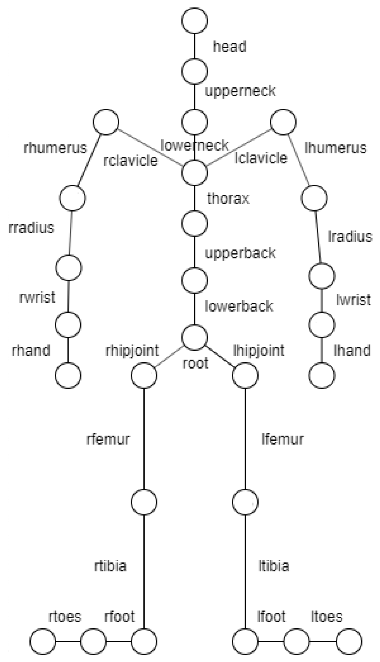
23]. This format consists of two files, Acclaim Skeleton File (ASF) and Acclaim Motion Capture data (AMC). The first contains information about the skeleton and the second about its movement in each frame. The skeleton is defined by a hierarchy of segments, as shown in Figure 2, where the root point represents the waist and is defined on a global coordinate axis. Each segment is represented by a line connecting two circles. The complete model is composed of 31 joints but in the figure only 27 joints are represented. It is missing the right and left finger joints and also the left and right thumb joints. The data used do not include them.
The ASF file displays information about the skeleton in a given initial pose. This file describes the direction, length, axis, degrees of freedom of each segment, and the limits of rotation. The root point is an exception for which only the initial position and orientation is given, which is reflected in the position of the entire skeleton in global space.
The AMC file contains the movement for the skeleton defined in the ASF file. Each frame describes the rotation of each segment in relation to the respective axis defined in the ASF file. In order for the skeleton to move in space, the position of the root segment is indicated.
The poses of the skeleton at each time instant are generated from the ASF and AMC files. These poses are made up of defined segments by their rotation and global position. The rotations from the AMC file are applied to the initial skeleton defined by the ASF, obtaining the rotation and global position of each segment at a given time.
In addition to the attributes taken directly from the ASF file, there are others that will be calculated during the movement update, namely:
  • Position: position of the end of the segment in the global coordinate system;
  • Rotation: current rotation, from the AMC file;
  • C: rotation matrix made up of “axis”;
  • C i n v : inverse C matrix;
  • M: global transformation matrix (rotation);
  • M Q u a t : global rotation, defined by a q u a t e r n i o n ( x , y , z , w ) , of the segment.
The process begins by analyzing the ASF file, defining a total of 31 segments. The initial positions are determined from this file. The position of the segment is defined by the end point of the segment. This point is calculated from the sum of the direction vector with a magnitude equal to the length of the segment and the position of the “parent” segment. This calculation is performed according to the hierarchy; therefore, the “parent” segment has already been determined. After calculating the positions of all the segments, the initial pose of the skeleton is obtained.
To determine the positions of the segments in the next frames, the skeleton hierarchy is traversed, starting at the root element and, for each one, the respective rotations from the AMC file are applied to the direction vectors and the position calculation is repeated.
As the AMC rotations are represented in relation to the ASF “axis”, while the direction vector is represented in the global coordinate system, it is necessary to create a global transformation matrix M that transforms these rotations to the same axis system as the direction vector. In the end, a set of poses is obtained (the skeleton of the human body) made up of 31 segments, each with information about its rotation and position in a global coordinate system.
The objectives of the two acquisition systems are different. The CMU Graphics Lab system, equipped with 12 infrared cameras, is used to build a large database with sequences of human body movements, and given its accuracy, has an associated ground truth. The aim of this work is to use CMU datasets to train a network to denoise the sequences acquired by the Kinect. These sequences contain the natural noise of the acquisition process, which is not estimated in this work. Therefore, there is no ground truth for the Kinect sequences and it is expected that the denoising process can only minimize the impact of occlusion noise.

3.2. Kinect Poses Denoising System

The Kinect sensor can be used to replicate the movement of the human body in a virtual character, for example, for virtual/augmented reality games. However, the occurrence of occlusions, i.e., parts of the body that the camera does not detect, is common, reducing the user experience. To analyze the occurrence of occlusions, a study was carried out with 33,000 poses captured by the Kinect sensor. Figure 3 shows a histogram of the occurrences of static poses for different occlusion values. It can be seen that 16% of the poses have occlusions, ranging from 1 to 6 occlusions per pose. This problem could be mitigated by using a system that can detect the occluded poses of the human body and predict the correct poses.
The aim of this work is to correct the poses of the human body captured by the Kinect using machine learning techniques, in particular deep neural networks. Therefore, the proposed model is based on a ResNet architecture. This type of method requires a large amount of training data. Thus, the network must be trained with a training set identical to the Kinect data, i.e., a set of 17 well-positioned joints containing the position and rotation. In the research carried out during the development of this work, no database was found with movements captured by Kinect and its meta-information suitable for the objectives of this work. To overcome this difficulty, the dataset provided by CMU Graphics Lab is used. These data differ from the Kinect data in the way they are captured (sensors setup) and also in the model used to represent the human body (skeleton). For this reason, the proposed model includes a block for adapting the CMU data to Kinect data.
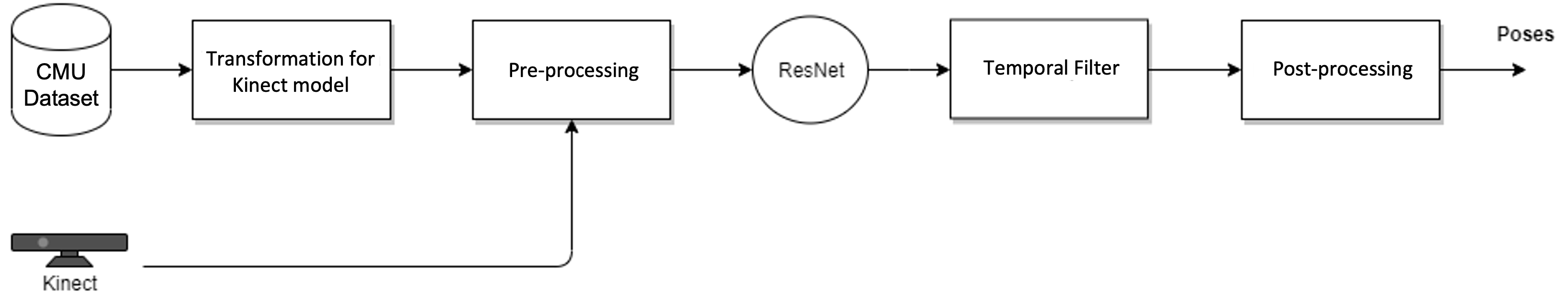
The approach developed in this work is represented by the block diagram shown in Figure 4. It begins with the process of transforming the skeleton defined by the CMU dataset to the Kinect skeleton.
The next block is related to the pre-processing of the data to avoid having to deal with skeletons of different sizes. Additionally, the global coordinates of the joints are transformed to the waist reference point (“waist” joint), reducing the number of joints configurations to one configuration per pose; i.e., whatever the position of the skeleton in the global reference frame, the joints for a given pose always have similar values.
The neural network implemented processes the poses individually, i.e., it has no temporal knowledge of the animation; therefore, jitter is likely to appear in the sequence of the returned poses. To combat this problem, the Savitzky–Golay [24] filter is applied to the output of the network, which smooths out the movement.
Finally, the inverse conversion of the pre-processing block is carried out in order to obtain the poses under the initial conditions.

3.2.1. Adapting the CMU Skeleton to Kinect

After obtaining a pose from the CMU dataset, the first step is to convert the segments to joints, making the skeleton a set of joints rather than segments. This conversion is achieved by going through the segment hierarchy. It is important to note the hierarchical model of movement in the human body. For example, in the relationship between the humerus segment and the elbow joint, the position of this joint is defined by the position of the humerus segment, but its rotation must affect the next joint, i.e., it is defined by the rotation of the “child” segment which, in this case, is the radius segment.
Then, only the joints similar to the Kinect skeleton are selected and the rest are removed. In Figure 5, the numbered joints in the CMU skeleton have been selected to represent the Kinect joints with their number.
For each human body movement sequence from the CMU dataset, the conversion is performed and the data are saved in a CSV file. The CSV file consists of the joint name, the components of the position ( x , y , z ) and rotation (quaternions), and the frame number. Concerning the quaternions, the “transforms3d” library is used to support the calculations for this unit. This library handles quaternions in the format ( w , x , y , z ), which is different from the Kinect and the Unity game engine (tool used to reproduce the human movement) convention ( x , y , z , w ). To convert to the desired format, the “w” channel is moved to last and the “y” and “z” coordinates are inverted:
[ w , x , y , z ] [ x , y , z , w ]
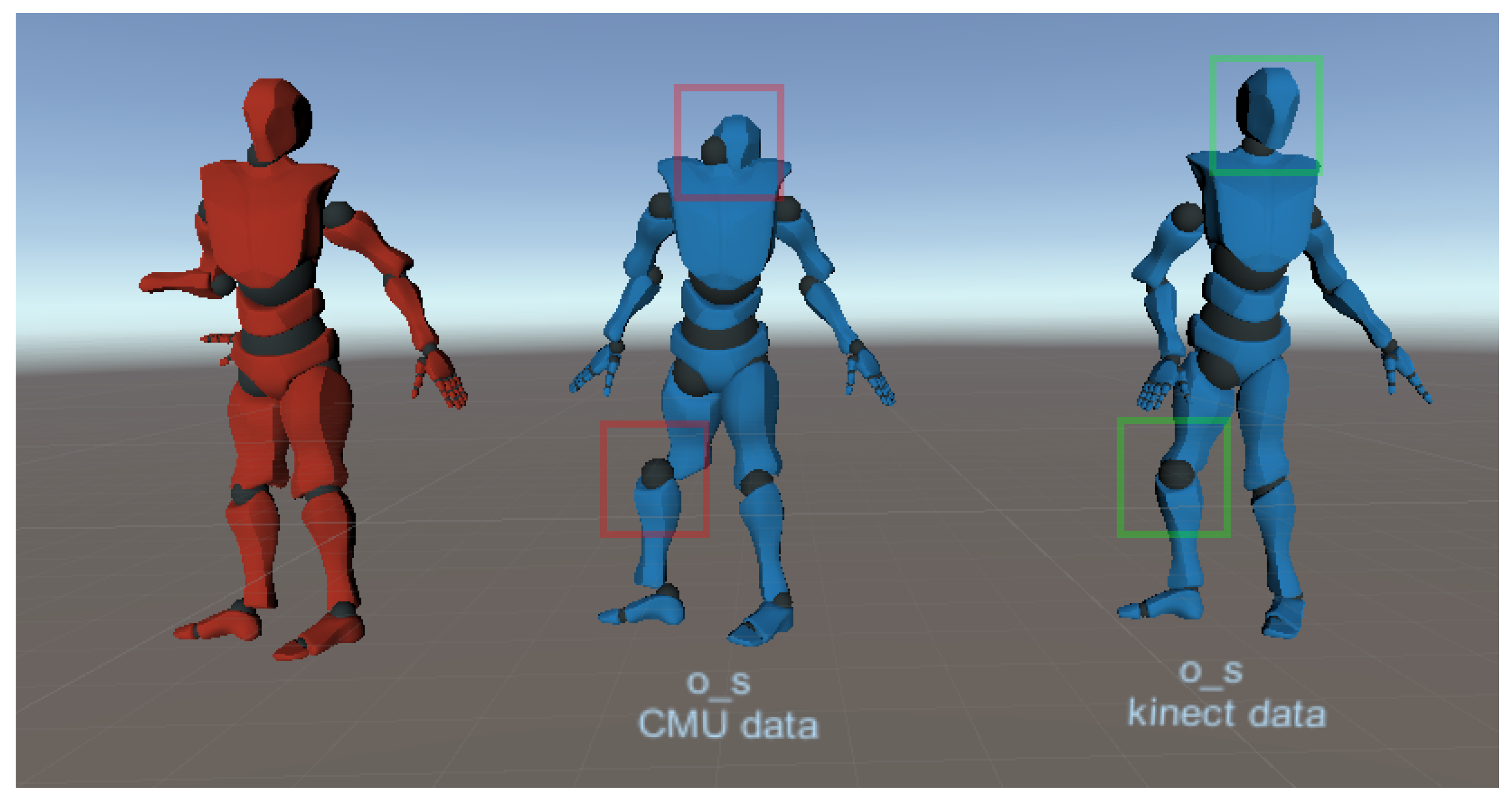
The mapping from the CMU skeleton onto the Kinect skeleton is a transformation between a more complete model with 31 joints to 17 joints from the Nuitrack model (Kinect). This simplification can introduce potential limitations in capturing certain movements or body configurations, increasing the diversity of noise that can be considered in the models. For the sake of simplicity, this problem is considered to be modeled by the noise associated with displacements, as described in Section 3.2.4.

3.2.2. Data Pre-Processing

To improve the DNN’s performance, the poses must be represented in a local coordinate system, always with the same origin point, to avoid distinguishing between poses that are the same but have different coordinates, i.e., each pose has a unique configuration. Therefore, the pre-processing functions convert the global coordinates of a given joint to a local coordinate system of a given origin; in this case the origin is the waist of the skeleton. Global and local transformation matrices are obtained to convert the poses to local and global coordinates.
The poses are scaled to normalize the height and to not have to deal with skeletons of different sizes, just different proportions. The scaling factor used is the average length of the segments, μ B o n e L e n , during the initial pose. For each pose, the joint hierarchy is traversed and the new positions given by Equation (2) are calculated; where p c u r r is the position of the joint to be normalized, p p a r the position of the “parent” joint, and p n o r m the normalized current position:
p n o r m = p p a r + p c u r r p p a r μ B o n e L e n
In other words, the normalized position will be the vector pointing from the “parent” joint to the joint to be normalized, divided by the average length of the segments.
The “waist” joint is the root of the hierarchy and, therefore, retains its original position. The joints should be traversed in a hierarchy, starting at the root, to ensure that the joints above it have their values updated. In the same way as the previous process, the average length of the segments should be saved for each movement in order to return to the original values.
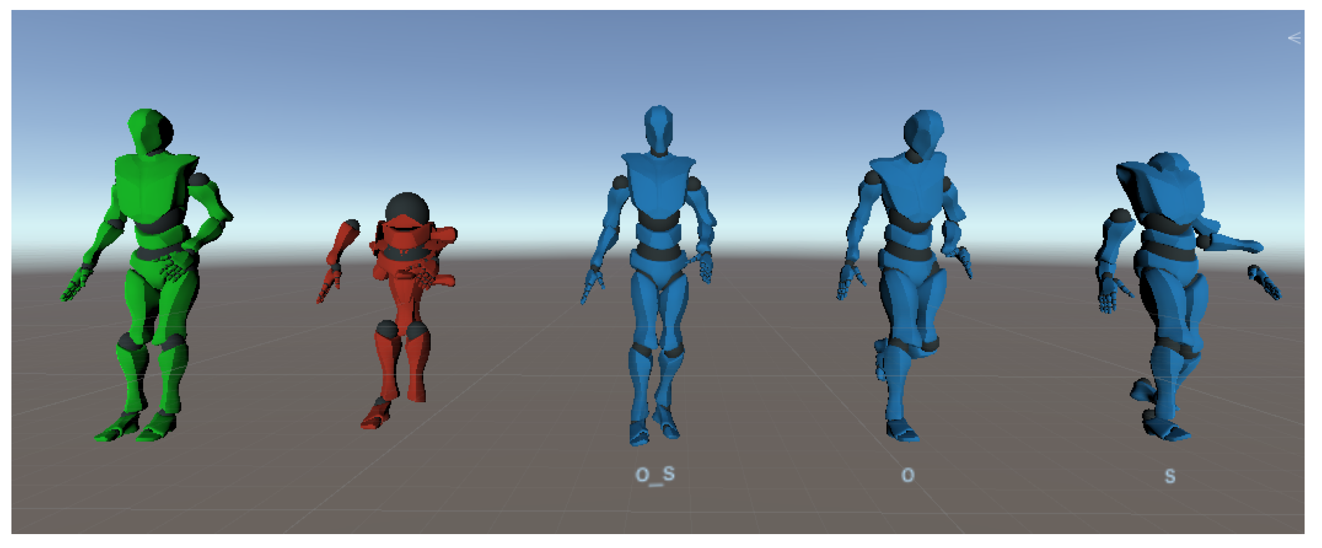
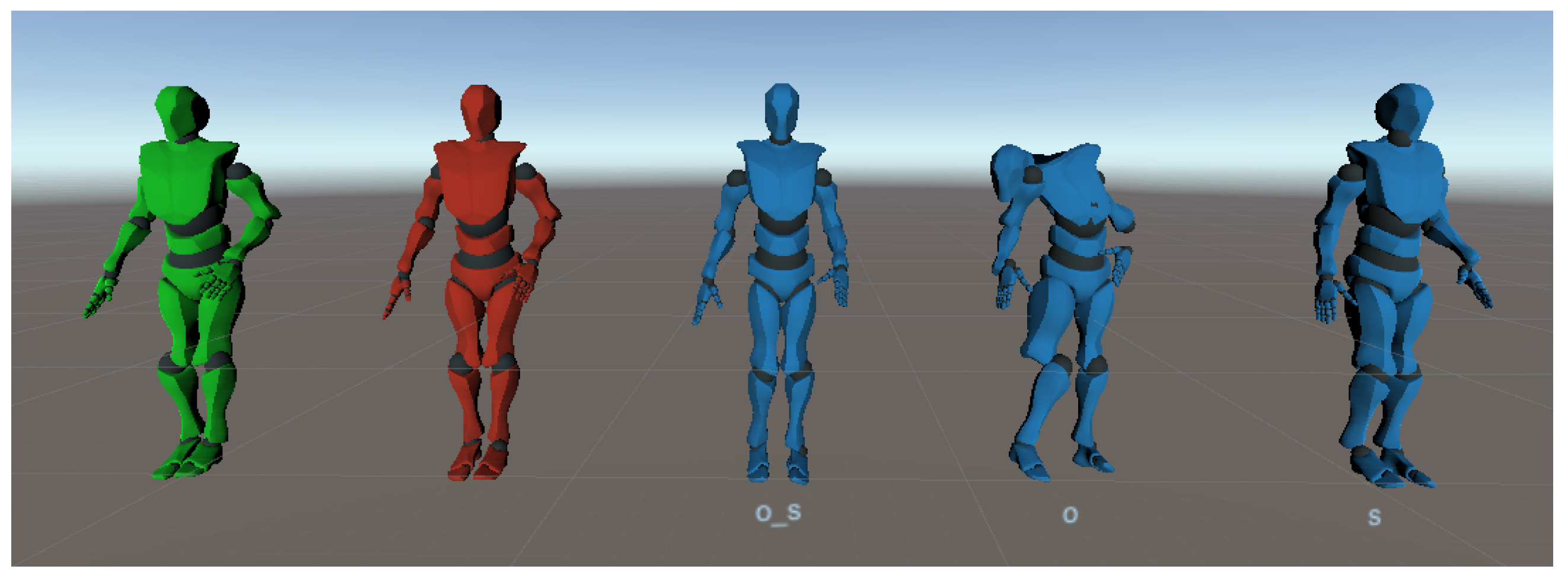
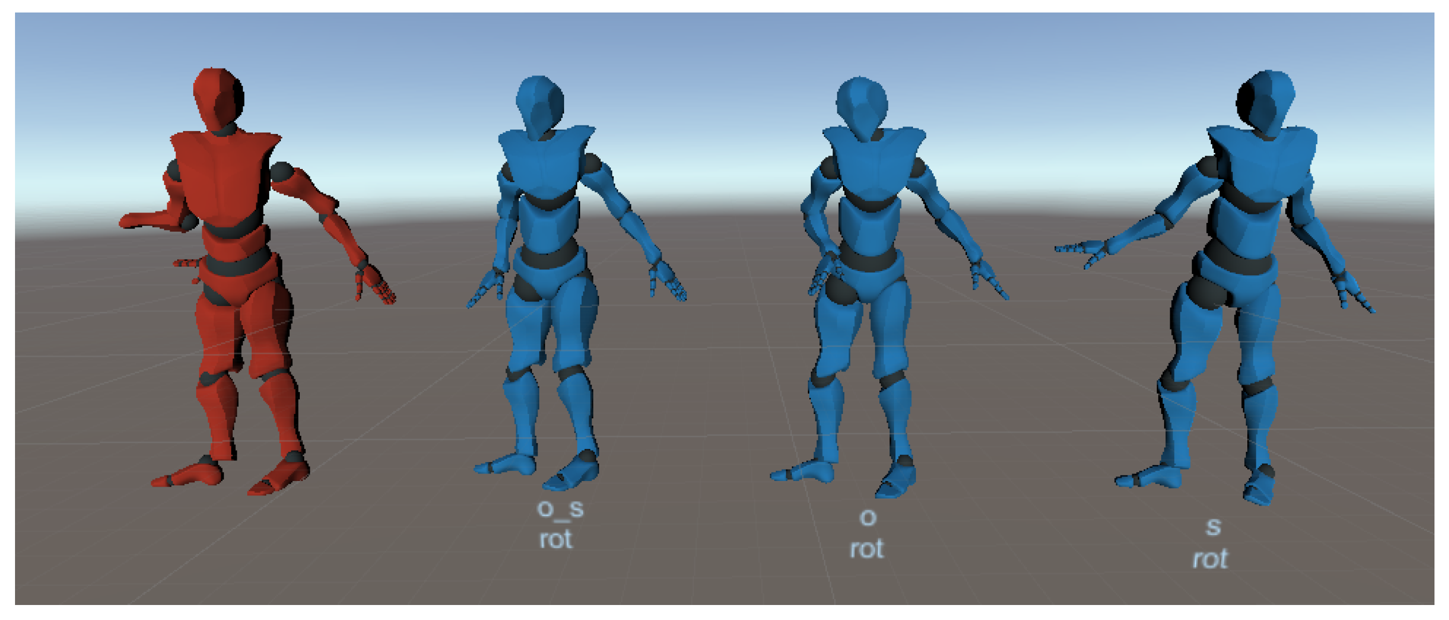
Finally, the rotations are adjusted to ensure that the direction vectors between the parent joint and the child joint are aligned with the respective axis. In this way, the same configuration of rotations represents the same pose, whether in the dataset of CMU or in the data returned from Kinect. Figure 6 illustrates an example where the rotation axes may not be aligned correctly. It is assumed that the direction vector of the “shoulder” joint should be aligned with the x-axis, and in the initial pose the rotation is ( 0 ,   0 ,   0 ) , as in first diagram in the figure. There may be cases where other direction vectors have been defined during the motion capture, as shown in the second diagram in the figure, in which case, although the pose is visually the same, the angle will not be the same as the previous one and from the perspective of the neural network it will be a new pose. An offset must be applied to the rotation in such a way that the x-axis coincides with the direction vector, as shown in the third diagram. After this, the rotation returns to the correct value.
The axis that must be aligned with the direction vectors depends on the type of joint. These axes have been defined as follows:
  • The right arm joints align the x-axis;
  • The left arm joints align the negative x-axis;
  • The joints from the waist to the head align the y-axis;
  • The joints of both legs align the negative y-axis.
The direction vector is given by the local position of the child joint; in the case of Figure 6, the vector is the local position of “elbow”. To determine the angle of rotation, the position is projected onto the respective planes, for example, if the aim is to align the x-axis then the point is projected onto the x–y plane to rotate in z and onto the x–z plane to rotate in y.

3.2.3. Deep Neural Network

The deep neural network block is used to eliminate noise from the poses captured by the Kinect. To achieve this, the original poses ground truth and the noisy ones are provided during the training phase, as illustrated in Figure 7. At this phase, the network will update its parameters throughout the iterations in order to reconstruct the original poses from the noisy ones. A ResNet-type neural network [25] is used.

3.2.4. Noise Function

The Kinect sensor captures pose information with two types of noise:
  • Occlusions: The joints move too far from the correct position because they are occluded by an object or part of the human body at the moment of capture.
  • Displacements: Small deviations of the joints from the correct position due to the sensitivity of the sensor and the environment in which it is located.
In order to simulate this noise in the network’s training data, a noise model is implemented. Occlusions and displacements are randomly generated, where the occlusions are chosen according to a variable with a uniform distribution and the displacements are based on a Gaussian distribution with zero mean and adjusted standard deviation.
The occluded joints take the position (0, 0, 0) and rotation (0, 0, 0, 1), while the displacements move slightly away from the original joint.
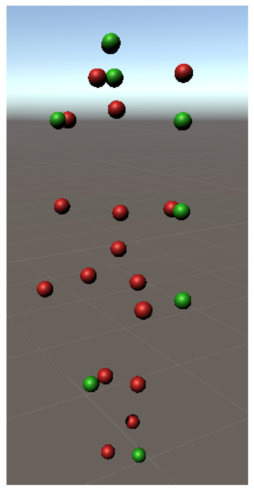
 Figure 8 and Figure 9 illustrate examples of the two types of noise, where the corrupted joints are shown in red and the ground truth in green. In Figure 8, the red joint that should overlap the green one has been moved to the origin (0, 0, 0) to simulate an occlusion, and in Figure 9, the red joints suffer some deviations to represent displacements.
When a joint is occluded, it is necessary to eliminate the rotation of the “parent” joint, because the network uses the direction vector to determine the position of the occluded joint. In the case of Kinect, when there is an occlusion it is impossible to determine the exact rotation of the ‘parent’ without knowing the position of the ‘child’ joint, leaving an incorrect value. In this way, the network will return an incorrect position, which is why it is necessary, in both Kinect and CMU poses, to change the rotation of the parent joint to [ 0 , 0 , 0 , 1 ] , so that the network learns to correct occlusions without knowing the direction vector.

3.2.5. Temporal Filter

The Savitzky–Golay filter [24] smooths data, in order to improve accuracy without distorting the signal, by convolution with a polynomial function of degree n. Given a set of points ( x j , y j ) , where j = [ 1 , , n ] , x is an independent variable and y is the observed value, the result of the filter is a set of convolutions between the signal and the coefficients C i , which depend on the length of the window m and the polynomial defined:
Y j = i = 1 m 2 m 1 2 C i y j + 1 , m 1 2 j n m 1 2

3.3. Network Implementation

As described in Section 3.2 and illustrated in Figure 4 the proposed system starts with the processing of the CMU dataset. Then, poses are captured with Kinect using Unity. Following this, the pre-processing of these data is performed. As for the neural network, the system begins by organizing the data produced followed by the training of the network. In the tuning process, several parameters are studied, in which the results for different values and their interpretation are analyzed. During training, the cross-validation method is used to measure the performance of the model more accurately. The training set is divided into 10 folds and approximately 10% of the data is used for validation. Finally, the temporal filter is applied on the sequence of poses returned by the neural network.
The proposed method is implemented in Python using the libraries for data processing and the TensorFlow API [26] to facilitate the implementation of the machine learning methods used. TensorFlow API has graphics processing unit (GPU) support, significantly speeding up the network training phase. TensorFlow supports other programming languages such as JavaScript and C#, ideal for developing applications in the Unity game engine, which in the context of this project is used to visualize poses in a more interactive way and detect problems that may occur.
The list of poses is made up of a set of joints which, in turn, are defined by their position ( t = [ t x , t y , t z ] ) and rotation ( r = [ r x , r y , r z , r w ] ), represented by quaternions. Decomposing the pose, the following is obtained:
j o i n t = [ t x , t y , t z , r x , r y , r z , r w ]
and
p o s e = [ j o i n t 1 , j o i n t 2 , , j o i n t n ]
that is,
p o s e = [ t x 1 , t y 1 , t z 1 , r x 1 , r y 1 , r z 1 , r w 1 , , t x n , t y n , t z n , r x n , r y n , r z n , r w n ]
The fact that the “waist” joint is the origin, means that it always has the same value [ 0 ,   0 ,   0 ,   0 ,   0 ,   1 ] , so it can be removed, leaving a total of 16 joints. Therefore, the pose is defined by a vector of 16 7   =   112 features.
The data for training the network (CMU poses) are pre-processed once and saved in the binary format. After loading all the training data, the order of the poses is shuffled so that the training and validation data are evenly distributed in terms of movement type (e.g., running or jumping), i.e., so that the two datasets do not contain just one movement type, as this would skew the results. A file is generated containing the original poses and three corrupted files with the different types of noise, keeping the order of the poses after the shuffle function. This avoids processing the data multiple times and guarantees the same conditions for all models.
In order to implement the ResNet architecture in TensorFlow in a modular way, a class structure was developed based on sequential blocks that facilitates model management (saving and loading previous models). In order to support different network architectures, a base class was created, which implements the general functionalities of the model. The “ResNetModel” class extends these functionalities and uses the “ResidualBlock” layers in the sequential model. The “SimpleModel” class follows the same approach but with dense layers provided by the API. The model settings are indicated in the “HyperParameters” class in order to group all the parameters in a single object. This structure allows for great abstraction in the network tuning phase. It can load previous models from the saved configurations and saved weights, even if “z-score” normalization is used because this is performed in the model itself, of the “CustomModel” type.
The ResNet architecture is made up of residual blocks which, in turn, contain one or more layers [27]. The example of defining the residual blocks in [6] is followed, each with a dense layer and a skip connection without additional layers. In this project, a similar architecture is implemented, excluding the markers and changing the number of residual blocks in each layer (dense layer). After testing different configurations, a ResNet of a residual block with a dense layer of 1000 neurons was obtained; shown in Figure 10.

3.4. User Evaluation

The movements captured with Kinect have no ground truth, making it difficult to see whether the network can correct these movements. To evaluate the network’s performance, we asked several users to visually evaluate the results obtained and give us their opinion via a questionnaire. This questionnaire also includes 29 different movements for evaluation, captured with this sensor, in which a video with 3 randomly ordered sequences is shown for each one. One of the sequences is taken directly from the sensor (without applying the deep neural network) and the other two are generated with the variants of the proposed denoising system with the best results.
For each movement, the participant is asked to select the sequence that represents the most natural movement. The questionnaire was sent to each participant via the Google Forms application, so that they could fill it in individually. In this work, the privacy and potential misuse of the poses captured did not represent any ethical issue since anonymous body models from the CMU dataset were used. The models were used to animate virtual characters without any connection to the users.

4. Results

This section presents and discusses the results obtained from the tests carried out to validate the proposed model. These tests are divided into two phases. In the first phase, the model is evaluated with a test set of CMU poses, different from the poses used to train the deep neural network, to assess its behavior in relation to the same skeletal structure that was trained. This evaluation is carried out using the mean absolute error (MAE) metric to measure the error between the original poses and those returned by the network. This metric is used because it is more robust to the presence of outliers, as present in the noise models proposed for occlusions and displacements. Tables and figures with the results refer to “corrupt” as the correct model with the errors introduced by the corrupt function. At this stage, tests are also carried out to check which of the types of noise introduced in the training is most appropriate (to simulate the real noise) and the differences between the number of features used, i.e., the differences between the model trained with the positions and rotations simultaneously and individually. In a second phase, the model is evaluated with a set of poses from Kinect, to check whether the model is able to correct the poses of the original Kinect skeleton, knowing that it has been trained with a similar structure. As the ground truth of the poses captured by Kinect was not available, it was decided to carry out a perceptual evaluation with 12 users. In this evaluation, users were asked to choose one of three different animations of the same movement. The first animation was obtained without applying the proposed model and the others with the application of two variants of the proposed model to correct the errors. The model used in the tests was trained with 885,823 training samples over 800 epochs. As for the test data, there were 88,582 samples, different from those used in the training.

4.1. CMU Data

In this phase, three noise situations are tested:
  • Noise caused by occlusions and displacements;
  • Noise caused by occlusions;
  • Noise caused by displacements.
The aim is to assess whether it is beneficial to train two models separately, one with occlusions and one with displacements. Figure 11 shows the errors of the poses returned by the model (in blue) trained with occlusions and displacements, as well as the error introduced in the test poses (in red). In the first graph of the figure, both types of noise were added to the test poses, in the second graph only occlusions were added, and in the third only displacements. Figure 12 and Figure 13 show the same type of information but for models trained only with occlusions and displacements, respectively.
The graphs, summarized in Table 2, show that the noise is significantly reduced, with the exception of the displacements, for which, although they try to smooth out the high frequencies, the total error increases. This is because in most poses the corruption function moves the joints to another possible position and the network tends to learn to always move the joints regardless of position. As a result, there will be more displacements and the error ends up being greater. However, this does not mean that the poses are not visually more correct. Figure 14 illustrates the correctness of a pose with displacements that is closer to the ground truth than the corrupt pose. The model trained exclusively with occlusions has the lowest error regardless of the type of noise applied to the test data. In Figure 15, it can be seen that this model manages to correct the occluded pose, making it similar to the true one.

4.2. Kinect Data

For the Kinect data, the network is unable to correct the poses with the same precision as the CMU tests. Figure 16, Figure 17, Figure 18, Figure 19, Figure 20 and Figure 21 show the obtained results, where “O” refers to the model trained with noise caused by occlusions; “O_S”, noise caused by occlusions and displacements; and “S”, displacements.
Despite the transformations made to approximate the structures of the two skeletons (CMU and Kinect), the positions of the joints are not exactly the same, which will influence the result of the network. A set of poses captured by Kinect was tested and occlusions and displacements were introduced with the implemented corruption function. Table 3 shows that in any of the training conditions, the error produced by the network is never smaller than the error introduced.
In this case, the displacement model causes the least noise, but that does not mean that the poses are visually closer to the original sequence. In order to understand the changes made by the network, the poses were observed in Unity (Figure 16). After testing the three models trained, the one that came closest to the original was the model trained with both types of noise. It managed to correct the position of the joint along with its rotation, unlike the model trained with occlusions, which although it seemed to achieve the right positions, failed with the rotations. Although the displacement model is not suitable for correcting noise, it does not cause as many changes to the joints when the supplied pose is noise-free, as shown in Figure 17. For this reason, and the fact that the other two models are not accurate, the total error of this model is the smallest.
After that, a real Kinect movement was tested, where there may occur occlusions and displacements. Since there was no ground truth information, the poses were observed in Unity where it was concluded that the predicted result was worse than the poses corrupted by the implemented function. Figure 18 shows that modeling the two types of noise simultaneously produces a pose that is closer to reality.
The network trained only with the positions of the joints also returns only the positions. This is undesirable because without the rotations we do not know the direction of the segments, resulting in the skeleton in Figure 19.
Unlike the model above, it is possible to train the network only with rotations as long as the position and rotation of the initial pose are known. From there, the transformations of the rotations are applied hierarchically. In Figure 20, none of the models were able to accurately predict the rotation of the occluded arm. Nevertheless, the models trained individually present more natural poses than the model trained with positions and rotations simultaneously.
The use of the temporal filter on the data returned by the network helps to reduce noise, especially the jittered caused by the network. The filter is used to add temporal information to the movements. It is a simple filter, favoring real time but with limitations for more complex movements (e.g., movements with acceleration). In addition to the improvements in the Kinect poses, the error is still higher than the error introduced (Table 4 and Table 5).
The difference in the results between the transformed CMU poses and the Kinect poses may be due to the fact that this transformation is not appropriate. For this reason, we added some poses acquired with the Kinect, without the presence of occlusions, to the training data, so that the network could learn the real structure of the Kinect skeleton. This procedure reduces the total error by 6.3 % compared to the previous model, considering the training data to only have rotations in the joints. As for the model trained simultaneously with position and rotation, there is a slight increase in the total error. However, it was observed that this model predicts poses that are visually closer to the real ones. Figure 21 shows an example of this situation, where the model trained with some Kinect data returns a pose closer to reality and with smaller deviations, especially in the position of the head and right knee.
It can, therefore, be concluded that adding Kinect poses to the training data is beneficial to the network even if the total error does not demonstrate it. It should be noted that in the results obtained for the Kinect poses using only CMU data in training the average error is small, only 0.03 (difficult to visualize) more than the error introduced by the corrupt function (Table 3). Naturally, the model has more difficulties with movements unknown to the network, but manages to eliminate some of the errors.

4.3. Evaluation with Users

Since there is no ground truth for the movements captured with Kinect, a visual user evaluation was provided. Therefore, 29 different movements captured with this sensor were presented and the participants gave their opinion through a questionnaire (full version of the questionnaire at https://forms.gle/kfZ4rr2nxkr2pg5AA, accessed on 28 February 2024). For each movement, a video with three randomly ordered sequences was shown. One of the sequences was taken directly from the sensor (without applying the deep neural network) and the other two were generated from the two models that showed the most natural poses visually, namely, the model trained with rotations and the model trained with rotations and positions. Both trained with occlusions and displacements. In the training of these two models, some Kinect poses were introduced which, as previously proven, improves the result along with the temporal filter applied.
For each movement, the participant was asked to select the sequence that represented the most natural movement. The tests were carried out on a group of 12 participants with computer science knowledge and 4 of them with experience in animation and 3D modeling. In order to reinforce the statistics, it would have been desirable to have a greater number of participants. However, the aim of this initial study was to see if visual validation could be a way forward in the future. Therefore, 12 participants was a reasonable number for the proposed objective. The questionnaire was sent to each participant via the Google Forms application, so that they could fill it in individually.
The result shown in Table 6 proves that the network has a positive effect on correcting Kinect poses. About 45 % of the answers point to the “ResNet” sequence (proposed model trained with positions and rotations) and about 35 % to “ResNetRot” (proposed model trained with rotations only) as the most natural sequence. Checking the two most natural sequences proves that the two models can generally improve the poses acquired from Kinect.
In order to analyze the behavior of the models when faced with different levels of occlusion, the movements were grouped into five scales according to the number of occlusions, where scale 1 corresponds to the lowest number of occlusions in the sequence and scale 5 to the highest number. The graph in Figure 22 shows the votes of users for each movement (“Kinect”, “ResNet”, “ResNetRot”) for the different occlusion scales. The number of votes in each scale has been normalized from 0 to 100 due to the different number of movements between them. It can be seen that in movements with few occlusions both networks have the same vote, considerably outperforming the original Kinect poses. At intermediate occlusion levels, 2 and 3, “ResNet” achieves the best results, followed by “ResNetRot”. The latter has a great impact on the poses with the highest number of occlusions, but surprisingly underperforms at the maximum level, in which case none of the networks can improve the Kinect poses.
Overall, the model trained with the positions and rotations seems to be the most suitable, which was expected given that it contains more features for training, although the sequences still show unnatural poses.

5. Conclusions and Future Work

The use of deep neural networks to solve denoising problems in motion capture applications shows promising results at the cost of a large set of training data.
The deep neural network-based system implemented manages to considerably reduce the noise of the poses in movements that have the same structure as those used in the training phase, i.e., both the training and test sequences are adapted from CMU dataset poses. However, tests with the Kinect sensor poses show that the network does not adapt as well to skeletons with a different architecture, even with the transformations between representations/models. The fact that the joints in the training data are not perfectly aligned with the joints in the Kinect skeleton negatively influences the prediction. This problem can be slightly mitigated by adding correct poses from the Kinect sensor, so that the network has some knowledge of the structure of the skeleton.
The obtained results do not always allow the best model to be determined. As explained in Section 4, the model trained with the displacements has a higher total error than expected, but is able to visually correct the corrupted CMU poses. It is difficult to determine which type of noise is most appropriate. According to the error results for the CMU tests, the model trained exclusively with occlusions achieves the best results in all three situations (1—test data with occlusions and displacements, 2—test data with occlusions, and 3—test data with displacements).
For the Kinect test data, each model serves its purpose, i.e., it best corrects the error for which it was trained. Although the total sum of the errors for these data is always greater than expected, the user tests presented in Section 4 show that the prediction made by the network, together with the application of the temporal filter, results in more natural movements, even if they present incorrect poses.
For future work, we intend to follow another process for adapting the skeleton, which consists of inverting this transformation, i.e., converting the Kinect skeleton to that of the CMU by adding the missing joints instead of eliminating them. Another possibility would be to build a dataset with the real skeleton of the Kinect sensor from three cameras to avoid occlusions in the joints. Finally, we intend to test the implemented system in a virtual/augmented reality application in order to analyze its performance in real time and its impact on the user experience.

Author Contributions

Conceptualization, A.C.G., R.J. and P.M.J.; methodology, A.C.G., R.J. and P.M.J.; software, A.C.G.; validation, A.C.G., R.J. and P.M.J.; formal analysis, A.C.G., R.J. and P.M.J.; resources, A.C.G.; data curation, A.C.G.; writing—original draft preparation, A.C.G. and R.J.; writing—review and editing, A.C.G., R.J. and P.M.J.; supervision, R.J. and P.M.J. All authors have read and agreed to the published version of the manuscript.

Funding

This research received no external funding.

Institutional Review Board Statement

Ethical review and approval were waived for this study due to the fact that participants were only asked to watch videos and give their opinion anonymously. All participants agreed to take part on a voluntary basis. Most of the videos used were obtained from the CMU database, respecting the rules defined by the CMU. Some videos were recorded with one of the authors of this work, respecting all ethical rules.

Informed Consent Statement

Informed consent was obtained from all subjects involved in the study and the participation in the study was voluntary.

Data Availability Statement

Questionnaire data are available upon request from the corresponding author.

Acknowledgments

The authors would like to thank all the participants for volunteering their time to conduct the experimental tests and for responding to the survey, as they gave us their time to contribute to our study. This work is supported by NOVA LINCS (UIDB/04516/2020) with FCT.IP.

Conflicts of Interest

The authors declare no conflicts of interest.

Abbreviations

The following abbreviations are used in this manuscript:
ASFAcclaim Skeleton File
AMCAcclaim Motion Capture data
APIApplication programming interface
CMUCarnegie Mellon University
DNNDeep neural network
GPUGraphics processing unit
KNNK-nearest neighbors
MAEMean absolute error
PCAPrincipal component analysis
ReLuRectified linear unit
ResNetResidual neural network
SDKSoftware development kit

References

  1. Nogueira, P. Motion Capture Fundamentals A Critical and Comparative Analysis on Real-World Applications. In Doctoral Symposium in Informatics Engineering; Universidade do Porto: Porto, Portugal, 2011; pp. 303–324. [Google Scholar]
  2. Xsens. Available online: https://www.xsens.com/ (accessed on 6 March 2024).
  3. Rokoko. Available online: https://www.rokoko.com/ (accessed on 6 March 2024).
  4. Shadow. Available online: https://www.motionshadow.com/ (accessed on 6 March 2024).
  5. Tian, C.; Fei, L.; Zheng, W.; Xu, Y.; Zuo, W.; Lin, C.W. Deep Learning on Image Denoising: An overview. Neural Netw. 2020, 131, 251–275. [Google Scholar] [CrossRef] [PubMed]
  6. Holden, D. Robust solving of optical motion capture data by denoising. ACM Trans. Graph. 2018, 37, 1–12. [Google Scholar] [CrossRef]
  7. Saito, J.; Holden, D.; Komura, T. Learning Motion Manifolds with Convolutional Autoencoders. In Proceedings of the SA’15: SIGGRAPH Asia 2015, Kobe, Japan, 2–6 November 2015; pp. 1–4. [Google Scholar] [CrossRef]
  8. Carnegie Mellon University. CMU Mocap Dataset. Available online: http://mocap.cs.cmu.edu/ (accessed on 6 March 2024).
  9. Wei, X.; Zhang, P.; Chai, J. Accurate Realtime Full-Body Motion Capture Using a Single Depth Camera. ACM Trans. Graph. 2012, 31, 1–12. [Google Scholar] [CrossRef]
  10. Cao, Z.; Simon, T.; Wei, S.E.; Sheikh, Y. Realtime Multi-person 2D Pose Estimation Using Part Affinity Fields. In Proceedings of the 2017 IEEE Conference on Computer Vision and Pattern Recognition (CVPR), Honolulu, HI, USA, 21–26 July 2017; pp. 1302–1310. [Google Scholar] [CrossRef]
  11. Fang, W.; Zheng, L.; Deng, H.; Zhang, H. Real-Time Motion Tracking for Mobile Augmented/Virtual Reality Using Adaptive Visual-Inertial Fusion. Sensors 2017, 17, 1037. [Google Scholar] [CrossRef] [PubMed]
  12. Fang, H.S.; Li, J.; Tang, H.; Xu, C.; Zhu, H.; Xiu, Y.; Li, Y.L.; Lu, C. AlphaPose: Whole-Body Regional Multi-Person Pose Estimation and Tracking in Real-Time. IEEE Trans. Pattern Anal. Mach. Intell. 2023, 45, 7157–7173. [Google Scholar] [CrossRef] [PubMed]
  13. Lugaresi, C.; Tang, J.; Nash, H.; McClanahan, C.; Uboweja, E.; Hays, M.; Zhang, F.; Chang, C.L.; Yong, M.; Lee, J.; et al. MediaPipe: A Framework for Perceiving and Processing Reality. In Proceedings of the Third Workshop on Computer Vision for AR/VR at IEEE Computer Vision and Pattern Recognition (CVPR) 2019, Long Beach, CA, USA, 17 June 2019. [Google Scholar]
  14. Kim, J.W.; Choi, J.Y.; Ha, E.J.; Choi, J.H. Human Pose Estimation Using MediaPipe Pose and Optimization Method Based on a Humanoid Model. Appl. Sci. 2023, 13, 2700. [Google Scholar] [CrossRef]
  15. Aristidou, A.; Lasenby, J. Real-time marker prediction and CoR estimation in optical motion capture. Vis. Comput. 2013, 29, 7–26. [Google Scholar] [CrossRef]
  16. Jesus, R.M.; Abrantes, A.J.; Marques, J.S. Tracking the Human Body Using Multiple Predictors. In Articulated Motion and Deformable Objects; Perales, F.J., Hancock, E.R., Eds.; Springer: Berlin/Heidelberg, Germany, 2002; pp. 155–164. [Google Scholar]
  17. Chai, J.; Hodgins, J.K. Performance Animation from Low-Dimensional Control Signals. ACM Trans. Graph. 2005, 24, 686–696. [Google Scholar] [CrossRef]
  18. Aristidou, A.; Cohen-Or, D.; Hodgns, J.; Shamir, A. Self-similarity Analysis for Motion Capture Cleaning. Comput. Graph. Forum 2018, 37, 297–309. [Google Scholar] [CrossRef]
  19. Memar Ardestani, M.; Yan, H. Noise Reduction in Human Motion-Captured Signals for Computer Animation based on B-Spline Filtering. Sensors 2022, 22, 4629. [Google Scholar] [CrossRef] [PubMed]
  20. Zhu, Y.; Zhang, F.; Xiao, Z. Attention-Based Recurrent Autoencoder for Motion Capture Denoising. J. Internet Technol. 2022, 23, 1325–1333. [Google Scholar]
  21. Zhu, Y. Motion Capture Data Denoising Based on LSTM Neural Network. In Frontier Computing; Chang, J.W., Yen, N., Hung, J.C., Eds.; Lecture Notes in Electrical Engineering, 747; Springer: Singapore, 2021; pp. 1353–1360. [Google Scholar] [CrossRef]
  22. Microsoft. Microsoft Kinect Sensor. Available online: https://www.microsoftpressstore.com/articles/article.aspx?p=2201646 (accessed on 6 March 2024).
  23. Acclaim. Acclaim ASF/AMC. Available online: https://research.cs.wisc.edu/graphics/Courses/cs-838-1999/Jeff/ASF-AMC.html (accessed on 6 March 2024).
  24. Savitzky, A.; Golay, M.J.E. Smoothing and Differentiation of Data by Simplified Least Squares Procedures. Anal. Chem. 1964, 36, 1627–1639. [Google Scholar] [CrossRef]
  25. He, K.; Zhang, X.; Ren, S.; Sun, J. Deep Residual Learning for Image Recognition. In Proceedings of the IEEE Conference on Computer Vision and Pattern Recognition (CVPR), Las Vegas, NV, USA, 27–30 June 2016; pp. 770–778. [Google Scholar] [CrossRef]
  26. Géron, A. Hands-On Machine Learning with Scikit-Learn, Keras & TensorFlow; O’Reilly Media, Inc.: Sebastopol, CA, USA, 2019. [Google Scholar]
  27. Sherstinsky, A. Fundamentals of Recurrent Neural Network (RNN) and Long Short-Term Memory (LSTM) network. Phys. D Nonlinear Phenom. 2020, 404, 132306. [Google Scholar] [CrossRef]
Figure 1. Nuitrack skeleton.
Virtualworlds 03 00007 g001
Figure 2. Hierarchical model of CMU dataset skeleton.
Virtualworlds 03 00007 g002
Figure 3. Histogram of the number of occlusions per pose.
Virtualworlds 03 00007 g003
Figure 4. System block diagram.
Virtualworlds 03 00007 g004
Figure 5. Mapping the CMU skeleton onto the Kinect skeleton.
Virtualworlds 03 00007 g005
Figure 6. Rotation axis correction.
Virtualworlds 03 00007 g006
Figure 7. Training data for the neural network.
Virtualworlds 03 00007 g007
Figure 8. Pose with generated occlusions.
Virtualworlds 03 00007 g008
Figure 9. Pose with generated displacements.
Virtualworlds 03 00007 g009
Figure 10. Network architecture that obtained the best results for the number of layers and neurons.
Virtualworlds 03 00007 g010
Figure 11. Tests with model trained with occlusions and displacements (shifts).
Virtualworlds 03 00007 g011
Figure 12. Tests with model trained with occlusions.
Virtualworlds 03 00007 g012
Figure 13. Tests with model trained with displacements.
Virtualworlds 03 00007 g013
Figure 14. Displacement correction. Green: true pose; red: corrupted pose; blue: predicted pose.
Virtualworlds 03 00007 g014
Figure 15. Correction of occlusions. Green: true pose; red: corrupted pose; blue: predicted pose.
Virtualworlds 03 00007 g015
Figure 16. Network results for Kinect test data with the corruption function implemented. Green: true pose; red: corrupted pose; blue: pose predicted by the network trained with the different types of noise.
Virtualworlds 03 00007 g016
Figure 17. Network results for a Kinect pose without additional error. Green: true pose; red: corrupted pose; blue: pose predicted by the network trained with the different types of noise.
Virtualworlds 03 00007 g017
Figure 18. Network results for noisy Kinect data. Red: corrupted pose; blue: pose predicted by the network trained with the different types of noise.
Virtualworlds 03 00007 g018
Figure 19. Net results, only with joint position information, for noisy Kinect data. Red: corrupted pose; blue: pose predicted by the network trained with the different types of noise.
Virtualworlds 03 00007 g019
Figure 20. Network results, with only joint rotation information, for noisy Kinect data. Red: corrupted pose; blue: pose predicted by the network trained with the different types of noise.
Virtualworlds 03 00007 g020
Figure 21. Network results for noisy Kinect data. Red: corrupted pose; blue: pose predicted by the network trained with/without the Kinect data.
Virtualworlds 03 00007 g021
Figure 22. Results of the questionnaire in relation to the level of occlusion of the animations. Occlusion at scale 1 groups all movements with few occlusions. Occlusion at scale 5 groups all movements with the highest number of occlusions.
Virtualworlds 03 00007 g022
Table 1. Main features of Kinect versions.
Kinect v1Kinect v2
Image Color640 × 480 30 fps1920 × 1080 30 fps
Image Depth320 × 240 30 fps512 × 424 30 fps
Range0.8∼4.0 m0.5∼4.5 m
Field of View (H/V)57/43 degrees70/60 degrees
Table 2. MAE error for different types of noise in training and testing.
CMU Test Data
Occlusions and DisplacementsOcclusionsDisplacements
Model TrainedOcclusions and Displacements0.04610.04200.0334
Occlusions0.03830.02390.0225
Displacements0.07660.07340.0303
Corrupt0.07240.06180.0127
Table 3. MAE error for Kinect test data.
Kinect Test Data
Occlusions and DisplacementsOcclusionsDisplacements
Model TrainedOcclusions and Displacements0.09300.08940.0830
Occlusions0.10960.08740.0928
Displacements0.10120.09890.0647
Corrupt0.06210.05220.0122
Table 4. MAE error for different types of noise in training and testing with temporal filter.
CMU Test Data—Temporal Filter
Occlusions and DisplacementsOcclusionsDisplacements
Model TrainedOcclusions and Displacements0.03970.03820.0314
Occlusions0.02890.02180.0172
Displacements0.0610.05990.0283
Corrupt0.07240.06180.0127
Table 5. MAE error for Kinect test data with temporal filter.
Kinect Test Data—Temporal Filter
Occlusions and DisplacementsOcclusionsDisplacements
Model TrainedOcclusions and Displacements0.08690.08600.0826
Occlusions0.09230.08140.0855
Displacements0.08680.08600.0655
Corrupt0.06210.05220.0122
Table 6. General questionnaire result.
Most NaturalSecond Most Natural
Kinect67107
ResNet (Rotations and Positions)157116
ResNetRot (Rotations)124125
Disclaimer/Publisher’s Note: The statements, opinions and data contained in all publications are solely those of the individual author(s) and contributor(s) and not of MDPI and/or the editor(s). MDPI and/or the editor(s) disclaim responsibility for any injury to people or property resulting from any ideas, methods, instructions or products referred to in the content.

