Review

The Role of Non-Destructive Testing of Composite Materials for Aerospace Applications

by
Thiago Luiz Lara Oliveira
*,
Maha Hadded
,
Saliha Mimouni
and
Renata Brandelli Schaan
Capgemini Engineering, 4 Avenue Didier Daurat, Parc Centreda—Bâtiment Synapse, 31700 Blagnac, France
*
Author to whom correspondence should be addressed.
Submission received: 30 September 2024 / Revised: 22 November 2024 / Accepted: 24 December 2024 / Published: 3 January 2025
(This article belongs to the Topic Nondestructive Testing and Evaluation)

Abstract

:
This review examines the essential application of non-destructive testing (NDT) techniques in assessing the integrity and damage of composite materials used in aerospace engineering, focusing on polymer matrix composites (PMCs), metal matrix composites (MMCs), and ceramic matrix composites (CMCs). As these materials increasingly replace traditional metallic and alloy components due to their advantageous properties, such as light weight, high strength, and corrosion resistance, ensuring their structural integrity becomes paramount. Here, various NDT techniques were described in detail, including ultrasonic, radiographic, and acoustic emission, among others, highlighting their significance in identifying and evaluating damages that are often invisible, yet critical, to parts safety. It stresses the need for innovation in NDT technologies to keep pace with the evolving complexity of composite materials and their applications. The review underscores the ongoing challenges and developments in NDT, advocating for enhanced techniques that provide accurate, reliable, and timely assessments to ensure the safety and durability of aerospace components. This comprehensive analysis not only illustrates current capabilities but also directs future research pathways for improving NDT methodologies in aerospace material engineering.

Graphical Abstract

1. Introduction

Composite materials have become increasingly important in the aerospace industry, frequently replacing conventional materials due to their enhanced mechanical properties, light weight, and corrosion and wear resistance [1]. Their integration into aircraft, originally driven by military applications, underwent a significant increase in civil aviation and aerospace applications in the 2000s [2]. Notably, during this decade, large aircraft models, such as the Airbus A380 and the Boeing Dreamliner, both containing a significant percentage of structural mass made from polymer composite materials, were developed. Composite materials for civil aviation are predominantly made with polymer matrix materials (PMC) reinforced with carbon and glass fibers, chosen for their favorable strength-to-weight ratios [3]. Thus, the increasing interest in the aerospace industry exemplifies the aim of using high-performance materials through the transition from heavy metallic alloys to composite materials. Advanced composite materials utilizing metallic alloys or ceramic matrices are undergoing continuous development. These materials hold promise for replacing traditional materials in various applications by offering functionalities akin to their polymeric counterparts. However, metal matrix composites (MMCs) and ceramic matrix composites (CMCs) often seemed as a future solution for areas that polymer composites cannot perform, such as exposition to high temperatures or damage tolerance. Thus, MMCs are an example of a class of composite materials that present an alternative to superalloys, offering a lighter material with superior properties, including enhanced hardness, thermal stability, mechanical strength, wear resistance, and corrosion resistance. Similarly, CMCs can supplant conventional materials in applications demanding high strength, fracture toughness, and low thermal expansion. Additionally, CMCs boast exceptional stability at extreme temperatures and significant oxidation resistance. When reinforced with ceramic fibers such as silicon carbide, these composites can maintain their structural integrity under thermal stress and resist environmental degradation [4]. Thus, they show adequate properties for dealing with temperatures around 1000 °C with minimal wear and are suitable for aerospace engine components and rocket nozzles [5].
Modern civil and military aircraft increasingly utilize composites to reduce mass while maintaining structural integrity. This shift is illustrated by the Boeing 787, which comprises 50% composite materials, a significant change from the 12% in the older Boeing 777. The Boeing 787 Dreamliner, using extensive composite materials, achieves a 25% reduction in fuel use and emissions compared to previous-generation airplanes, demonstrating substantial improvements in fuel economy and environmental impact [6]. Analogously, Airbus has increased the volume of composite materials used in its aircraft, with the A350 featuring 53% composites in its airframe [7].
The most common types of composites used in aerospace applications consist of a matrix resin reinforced with fibers. In this sector, the primary polymeric resins are thermosets, with limited use of thermoplastics, while the prevalent reinforcements are glass fibers, carbon fibers, and aramid fibers [8,9]. The widespread adoption of these high-performance composites over recent decades has been driven by advancements in materials engineering sciences. The significant weight savings not only improve fuel economy and extend travel distances but also contribute to reduced carbon emissions [10]. Studies have shown that the use of composite materials in aircraft can lead to substantial C O 2 savings over their lifecycle due to reduced fuel consumption during flight, despite higher emissions during production and recycling [11]. One example of the significance of employing composite materials in the aviation industry is the fact that their performance is often mechanically superior to aluminum alloys [12]. Estimations indicate that 30% of flight costs are due to fuel consumption. One way to mitigate costs and mitigate pollution is by reducing aircraft weight, which is achieved by using composite materials and other advanced high-performance materials [13,14].
Among the main drawbacks of fiber-reinforced polymeric materials is the determination of service life and repair. As with any other structure subject to a dynamic environment, composite materials for aeronautical applications are subject to a wide variety of loading modes and impacts, which can lead to damage, delamination, and ultimately catastrophic failure [15]. Ceramic and metallic composite materials are currently in development to address those limitations, especially for applications dealing with high operational temperatures and parts subject to wear. However, the current use is limited due to the highly complex design manufacturing, recurring brittleness issues, and the high cost of manufacture [16,17].
The damage mechanisms and behavior for this class of materials are distinct. The study of defect characterization within these classes of materials is a complete field of study, with researchers continually developing techniques to identify and ways to define damage and defects. For example, for PMC, there is a wide variety of damage defects, notably highlighting the phenomena of micro-cracking and delamination [18]. These challenges have allowed for the development of strategies to address these issues and enhance functionality. In this case, for example, the development of studies includes self-healing capabilities, adding structural and non-structural repair to the materials [19,20]. Damage assessment and evaluation of high-performance parts entail considerable costs, especially for such materials as the ones used for aerospace applications. Thus, it is relevant that their evaluation does not generate significant damage to the components. This requirement shows how non-destructive techniques (NDT) are particularly suitable for detecting, locating, and monitoring damage without compromising the material properties. Consequently, this need has encouraged the development of advancements regarding NDT methods [21]. Using NDT encompasses a suite of analytical techniques designed to identify, locate, monitor, and evaluate defects or defects in materials or structures. The damage assessment, evaluation, and behavior vary along with the different materials and service life characteristics (environment hazards and loadings), and thus, different NDT techniques are properly sensible or prone to certain material and damage characteristics. Thus, the use of the probability of detection (PoD) for NDT is a valuable tool, since it can quantify the reliability of an NDT technique by determining the likelihood that it will successfully detect a defect of a given size under specific conditions, ensuring the effectiveness and safety of the inspection process [22]. A relevant aspect of NDT is the use of techniques to monitor damage evolution or increase, and it is a suitable method of detecting damage before it escalates to a degree that could compromise the lifespan of a component. Additionally, NDT can be used during the manufacturing process to ensure material quality, opening opportunities for automated online monitoring and quality control in the future [23]. The main characteristic of this form of inspection is that it can be conducted throughout the operational life of the component and does not alter the material properties or inflict significant damage [24]. Regarding NDT methods employed in composite materials to assess damage, there is a significant group of techniques that can be used in either passive or active approaches to interact with chemical, electromagnetic, or physical spectra. The NDT methods usually applied to composite materials include visual inspection, ultrasonic inspection, acoustic emission techniques, dielectric techniques, radiographic testing, infrared thermography, shearography, and holography, among others [25]. The development of new and advanced composite materials has a significant impact on NDT techniques, and vice versa. This includes not only creating new NDT methods but also finding new ways to use existing non-invasive techniques.
Artificial intelligence (AI) is a growing technology and can be potentially used for NDT analyses. Its potential application in NDT holds promise for real-time monitoring and analyses through big data and the creation of digital twins. For structural health monitoring, there is potential for embedding sensors and for modifying materials to make them easier to analyze.
This review aims to explore the theme of non-destructive testing (NDT) for composite materials in the aerospace industry, highlighting its main applications and capabilities. Additionally, the review will delve into methods for damage identification across diverse NDT techniques and examine potential future applications that could drive innovation and evolution in this sector. By analyzing current NDT practices and emerging technologies, the paper provides a comprehensive understanding of the state of the art and prospects of NDT in composite materials. This will contribute significantly to the advancement of knowledge and technology in the field, ensuring the continued safety, reliability, and efficiency of aerospace structures.

2. Overview of Composite Materials

Composites originated in 3400 B.C., with mud and straw for construction purposes, while modern composites emerged in the early 1900s with the development of plastics like vinyl, polystyrene, phenolic, and polyester [26], which offered superior structural properties compared to natural resins. However, these early plastics lacked sufficient mechanical strength for structural applications, necessitating reinforcement to achieve the required strength and stiffness.
The modern era of composites advanced significantly with Owens Corning’s introduction of fiberglass in 1935, which combined glass fibers with plastics to create robust and lightweight structures, marking the beginning of the carbon fiber-reinforced polymers (CFRP) sector [27]. In the 1970s, the industry progressed further with DuPont’s development of Kevlar, a high-strength, lightweight fiber that is crucial for aerospace and armor applications [28,29]. Despite these advancements, challenges such as material flaws and bonding issues can still lead to structural failures, underscoring the importance of careful analysis of composite interfaces and wettability [30,31]. Composites continued to evolve over time, with various combinations of matrices and reinforcements yielding different mechanical properties, where the main types included ceramic composite materials, metal matrix composites, and polymer matrix composites.

2.1. Ceramic Composite Materials

Ceramic composite materials use ceramics as the reinforcing matrix, exhibiting either an amorphous or crystalline microstructure. They are noted for their high thermal stability, environmental resistance, hardness, low thermal and electrical conductivity, and minimal thermal expansion. These traits provide advantages such as wear resistance, high operational temperatures, high strength, and a high Young’s modulus. However, CMCs are also brittle and show low fatigue resistance and poor impact energy absorption. Additionally, voids and porosity can adversely affect their mechanical properties. To improve performance, manufacturing processes aim to minimize such aspects, thereby enhancing overall performance.
In aerospace engineering, CMCs are developed to reduce weight and improve mechanical performance at high temperatures. Their toughness, wear resistance, and thermal tolerance make them ideal for turbine blades, which benefit from their lightweight nature and high thermal resistance, allowing for greater thrust and speeds, as Figure 1 illustrates the aforementioned performance of various types of composites in terms of specific strength as a function of temperature. Additionally, CMCs are also promising for aircraft brakes, handling temperatures up to 1500 °C while reducing weight [32]. They are used in other high-temperature applications that can include exhaust systems, turbines, and nose cones, where their thermal stability and durability are critical.
The performance of CMCs is closely linked to the quality and precision of their manufacturing process, which remains in its early development stages and is generally costly, thus limiting their widespread application. Previous studies have demonstrated that void volume significantly affects the mechanical performance of CMCs, with an increase in voids leading to a notable decrease in mechanical strength [33]. The interface between the fiber and matrix is crucial to the fracture toughness of CMCs, with fiber coatings enhancing material strength. A weaker mechanical interface can improve toughness by allowing for controlled debonding and sliding between the fibers and the matrix under significant loading. This controlled debonding absorbs more energy and distributes stress, thereby preventing catastrophic failures that are typical of brittle materials. Coatings improve the damage tolerance of composite materials by modifying the interface behavior, thus enhancing overall performance and durability [34].
Figure 1. Strength of diverse materials as a function of operational temperatures. Modified [35].
Ndt 03 00003 g001

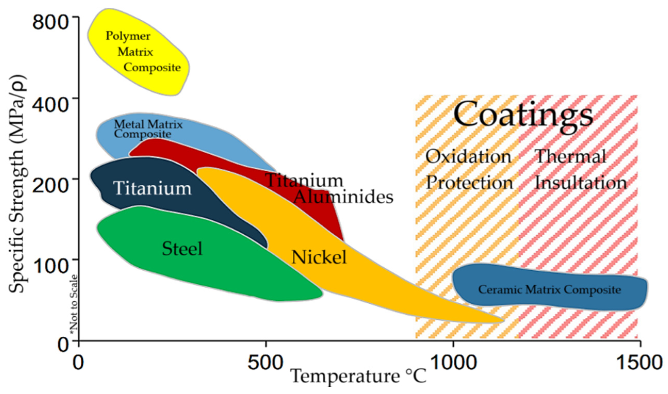
2.2. Metal Matrix Composites

Metal matrix composites (MMCs) are materials that feature at least one metallic component as the continuous matrix phase. The reinforcement in these composites can include fibers, whiskers, or particles that are present in one or more phases. Each type of reinforcement offers unique mechanical benefits and can be made from various materials [36].
The metallic matrix is often coupled with ceramic reinforcements, enhancing the mechanical stability at elevated temperatures. The fibers used in MMC reinforcements include steel, asbestos, carbon, glass, aluminum, tungsten, polyester, and quartz fibers [37]. Each type of fiber offers different advantages. Steel fibers provide high strength and durability. Asbestos fibers, although less commonly used due to health concerns, offer excellent thermal resistance. Carbon fibers are known for their high stiffness and low weight. Glass fibers offer a balance of strength and cost-effectiveness. Aluminum and tungsten fibers contribute to high strength-to-weight ratios and thermal stability. Polyester fibers offer good mechanical properties and chemical resistance. Quartz fibers provide exceptional thermal and electrical properties. Specific applications highlight the use of boron fibers in aluminum matrices for aerospace structures, such as space shuttle components, due to their significant weight savings and mechanical strength. Silicon carbide (SiC) fibers are frequently used for their excellent mechanical properties and compatibility with titanium and aluminum matrices. Additionally, graphite fibers in Mg-matrices demonstrate advancements in manufacturing techniques, such as filament-winding vacuum-assisted casting.
Particulate reinforcement in MMCs involves the use of ceramic particles, such as alumina (Al2O3) and silicon carbide (SiC), dispersed within the metal matrix to enhance various properties. Particle size significantly influences the mechanical properties of composites. Smaller particles can lead to increased interface strength but may also introduce more porosity and aggregation issues. Larger particles typically result in better load transfer and higher overall strength at the interface. The influence of particle size on the adhesion between ceramic particles and the metal matrix is critical. For instance, in Cu-Al2O3 composites, coarse alumina particles (180 µm) resulted in a higher interface strength compared to fine particles (<3 µm), with values of 74 ± 4 MPa and 68 ± 3 MPa, respectively. This difference is attributed to the better bonding quality observed with coarse particles, which also helped reduce intergranular porosity and enhance overall mechanical properties such as hardness and density. Fine particles tend to form agglomerates that do not bond well during the sintering process, leading to weaker interfaces and increased porosity [38].
These composites combine the useful properties of metals, such as ductility and thermal conductivity, with the high strength, stiffness, and wear resistance of the reinforcing materials. The advantages of MMCs include designed specific strength and stiffness, the potential for improved wear and corrosion resistance beyond metal alloys, and superior thermal stability compared to unreinforced metals.
The matrix–reinforcement interface is crucial for load transfer and overall composite performance, where coatings are often employed to prevent chemical reactions, improving bonding and wettability [39]. The interface performance significantly impacts the mechanical response of MMCs, making precise property characterization essential for efficiency optimization. One effective method is the single fiber push-out test, which assesses fiber–matrix adhesion. Inadequate bonding can result in fiber slippage under stress, leading to premature composite failure. Weak interface shear strength hinders effective load transfer, forcing the matrix to bear more load than initially intended, compromising the overall structural integrity. Proper wettability between the fiber and the matrix enhances bonding strength. Advanced manufacturing techniques, such as squeeze casting, which applies high pressure to ensure thorough wetting of the fibers by the liquid matrix, are commonly employed to improve interfacial bonding and reduce the risk of fiber pull-out. Moreover, the use of external bonding agents or fiber coatings can further enhance wettability and the resultant mechanical properties of the composite.
The use of MMCs in aircraft structures is predominantly associated with superalloys as a matrix phase, such as aluminum, magnesium, and titanium alloys [40]. Table 1 presents the typical properties of metallic alloy matrix phases and their preferential use for aerospace applications. Titanium matrix alloys excel at high temperatures with a superior strength-to-weight ratio, maintaining structural stability at temperatures where aluminum matrices would melt. Though more expensive, titanium alloys outperform aluminum alloys, which can be more cost-effective for lower-demand structural components [41].
Aluminum metal matrix composites (AMMC) combine aluminum with reinforcements such as silicon carbide and aluminum oxide (Al2O3) to enhance their properties, like strength, stiffness, hardness, thermal conductivity, controlled thermal expansion, and improved wear and corrosion resistance [42]. The low density of aluminum makes AMMCs lightweight and advantageous for applications in aerospace industries. The addition of other metals, like silicon, copper, magnesium, and zinc, can further enhance specific properties of the alloy, including casting characteristics, strength, machinability, and corrosion resistance.
AMMCs are used across various industries. For instance, in the automotive sector, they are employed in components like pistons, brake rotors, and connecting rods for their strength and wear resistance. In aerospace applications, AMMCs are used for aircraft structures and helicopter blades due to their high strength-to-weight ratio. In the marine industry, AMMCs are used for boat hulls and ship components because of their corrosion resistance and lightweight properties. The AMMCs can also be used in heat sinks and electronic packaging for effective heat dissipation by diverse sectors. The defense sector uses AMMCs in tank armor and military aircraft parts that deal with peak temperatures of up to 400 °C. In the construction sector, AMMCs can be used in bridge decks, window frames, and door panels for their high stiffness and durability [17].
Titanium alloys are also used as a matrix phase for MMCs. The combination of titanium with reinforcements such as tungsten carbide (WC) results in composites with enhanced mechanical properties. For instance, Ti-MMCs reinforced with WC exhibit a hardness of 417 BHN, a tensile strength of 522 MPa, and an impact strength of 14 J, making them suitable for demanding environments where mechanical strength and wear resistance are critical, such as aerospace applications [43]. Magnesium alloys as MMCs have also gained significant attention due to the combination of properties, which include low density and good surface-to-volume ratio, tensile strength, and thermal conductivity. Research evaluated the incorporation of carbon nanotubes (CNTs) into magnesium matrices and showed improved mechanical and microstructural properties, including tensile strength, yield strength, and ductility. The dispersion of CNTs within the matrix also contributes to fracture resistance by inhibiting crack propagation. However, challenges such as poor wettability and CNT agglomeration impact the bonding interface and overall composite performance. Despite these issues, the potential applications of Mg-MMCs in the biomedical, aerospace, and automotive sectors continue to drive research and development in this area [44].
Table 1. Properties and aerospace applications of aluminum, magnesium, and titanium matrix alloys.
Matrix AlloyDensity (g/cm3)Modulus of Elasticity (GPa)Operational
Temperature (°C)
Application
Aluminum [45]2.8171.7150 °CFuselage, wing structures, engine components
Magnesium [46]1.8444.2300 °CAircraft brackets, helicopter components, lightweight structures
Titanium [47]4.43114400 °CHigh-temperature engine components, landing gear
Table 1 compares the properties and applications of three of the most used matrix alloys used in aerospace engineering: aluminum, magnesium, and titanium. Aluminum, with a density of 2.81 g/cm3 and a modulus of elasticity of 71.7 GPa, is used in fuselages, wing structures, and engine components due to its light weight and moderate heat resistance (up to 150 °C). Magnesium, the lightest structural metal used in the industry, has a density of 1.84 g/cm3 and a lower modulus of elasticity of 44.2 GPa, but can operate at temperatures up to 300 °C, making it suitable for aircraft brackets, helicopter components, and other lightweight structures that may encounter moderate heat. Titanium stands out with its higher density of 4.43 g/cm3 and the highest modulus of elasticity at 114 GPa, enabling it to endure operational temperatures of up to 400 °C. This makes it relevant for high-temperature engine components and landing gear, where strength and high thermal tolerance are essential. These alloys are often chosen for their balance of weight, strength, elasticity, and thermal properties, optimizing the performance and efficiency of aerospace structures in line with modern aerospace design requirements.
Table 2 summarizes the different composite materials used in the aerospace industry. Silicon carbide and aluminum oxide are preferred for their high hardness and wear resistance, making them suitable for components such as turbine blades and engine parts, where durability under high stress and temperature is crucial. Carbon nanotubes are suited for enhancing structural components and electrical applications within aircraft to boost performance and efficiency, given their elevated tensile strength and lightweight characteristics. Boron fibers are utilized in aircraft structural parts due to their high thermal stability and durability, particularly under high-temperature conditions. Finally, graphene, known for its high thermal conductivity and strength under strain, is increasingly used in high-performance applications, such as satellite components. Collectively, these materials exemplify the strategic selection based on specific aerospace needs, ensuring optimal functionality and safety in various aerospace contexts, from standard commercial aircraft to advanced satellite systems.

2.3. Polymer Matrix Composites

Polymeric matrix composite materials are the most widely used industrially, offering a high strength-to-weight ratio alternative for mild operational temperature environments. The advantages of polymeric composite materials also include significant fatigue resistance and chemical stability. The resin matrix is divided into two groups based on their thermal response: thermoset and thermoplastic resins. Composite materials with thermoset matrices, such as epoxy and phenolic resins, offer excellent thermal stability and mechanical properties. However, they are typically brittle and non-recyclable due to the irreversible chemical bonds formed during the curing process, which creates a rigid and infusible structure. In contrast, thermoplastic composites, like PEEK (polyether ether ketone) and PEKK (polyether ketone ketone), offer high impact resistance, recyclability, and a higher potential for repair and reshaping. These polymeric resin composites are widely used in the aerospace industry, where they contribute to weight reduction and improved fuel efficiency [53]. Table 3 shows various polymers used in aerospace applications, each selected for specific properties like thermal stability, mechanical strength, and density.
The advantages of polymeric composite materials are closely tied to the type of reinforcement used. Common reinforcements, such as glass, carbon, aramid, and polybenzimidazole fibers, enhance the strength of the resin matrix [58]. Glass fibers are the most widely used due to their high tensile strength. Polybenzimidazole, an advanced option, is known for its excellent thermal and chemical stability, retaining mechanical properties at high temperatures. Despite its high performance, the complex and costly manufacturing process restricts its applications to the aerospace and defense sectors. For more cost-effective improvements, fillers and additives are used to enhance resin properties. For instance, silica fillers improve dielectric properties and abrasion resistance, while calcium carbonate enhances the rigidity and thermal stability of the composite [59]. Additives, on the other hand, are incorporated to modify the processing and performance characteristics of composites. These include plasticizers, stabilizers, lubricants, and anti-shock agents. In this case, the addition of stabilizers aims to protect the polymer from thermal or environmental degradation, while lubricants facilitate material flow by reducing friction during the manufacturing process [60,61].
Table 4 compares the mechanical properties of various fiber reinforcements used in polymer matrix composites that are commonly employed in aerospace parts. Aramid fibers, with a modulus of elasticity of 130 GPa and a tensile strength of 2800 MPa, provide the impact resistance necessary for astronaut vests and helicopter rotor blades, reflecting their high strength and moderate flexibility. Carbon fibers stand out with the highest modulus of elasticity (294 GPa) and tensile strength (7060 MPa), making them ideal for structural components, such as wing structures and the fuselage, where a high strength-to-weight ratio is essential. Glass fibers, available in S-type and E-type, offer more flexibility with a higher elongation at break, which are suitable for less critical applications such as aircraft interiors and secondary structural parts. S-type glass fibers provide a balance between cost and performance, with a modulus of elasticity of 85.5 GPa and tensile strength of 4585 MPa, while E-type fibers are used in non-structural parts due to their lower modulus of elasticity (13.5 GPa) but still respectable tensile strength (3450 MPa). This table highlights the strategic selection of fiber types based on durability, cost-effectiveness, and mechanical performance requirements, ensuring the optimal functionality and safety of aerospace vehicles.
While conventional polymer matrix composites reinforced with fibers offer significant advantages in terms of strength and stiffness, their susceptibility to damage and impact remains a critical challenge. Aiming to overcome these limitations, researchers have developed polymer matrix hybrid composites. These materials represent an innovative class of composites where multiple reinforcing elements are engineered and combined within a polymer matrix. This synergistic approach allows for the creation of composites with superior properties compared to their single-fiber counterparts [64]. An example of this material design is GLARE (glass laminate aluminum-reinforced epoxy). This hybrid composite integrates aluminum and glass fibers within an epoxy matrix, which significantly enhances the structural integrity and performance characteristics, offering a combination of the lightweight properties of aluminum with the high tensile strength and resistance provided by glass fiber [65]. This material is particularly notable in aerospace applications, where its high strength-to-weight ratio, excellent fatigue resistance, and superior damage tolerance are critical. Moreover, GLARE’s ability to be engineered with different layers and orientations allows for the optimization of its strength and weight properties according to specific requirements. This adaptability, combined with its inherent resistance to corrosion and fatigue, underscores the relevance and increased use of it over other materials in aerospace engineering [66]. The usefulness of it in aircraft structures is particularly significant for parts of the fuselage and the leading edges of tail surfaces, where impact damage is a solid concern.

3. Mechanisms of Damage in Composite Materials

Composite materials can provide greater stiffness, fatigue resistance, and environmental surface resistance. However, these advantages are accompanied by complex damage mechanisms and behavior, with property variations due to anisotropy, heterogeneity, and manufacturing defects. Understanding damage mechanisms is essential to be able to design composite parts [31]. In service, component failure often results from a combination of factors that simultaneously degrade the material’s local properties, with fatigue being a significant contributor. Fatigue failure in components or composite structures is a complex process driven by multiple interrelated causes, all of which contribute to the progressive deterioration of the material’s properties.
Environmental factors, such as temperature changes, chemical exposure, and humidity, have a significant impact on mechanical qualities at low cycle numbers. Mechanical factors like overloading, vibration, and impact can accelerate fatigue progression, while material characteristics, such as inherent flaws, microstructural composition, and surface finish, are crucial for determining fatigue resistance. Manufacturing processes may introduce residual stresses and defects that compromise material integrity. Design errors, such as overestimating material strength or improper stress distribution, significantly contribute to fatigue failure. Additionally, operational variables, such as fluctuating loads, insufficient maintenance, and improper use, can further hasten material degradation. Different composite materials may be more susceptible to specific types of damage, and NDT techniques are more effective at detecting particular types of damage in these materials.
Polymer matrix composites are more susceptible to a variety of damage mechanisms, including delamination, matrix cracking, fiber breaking, and interfacial debonding, as shown in Figure 2 for a fatigue test. The fatigue test demonstrates three distinct stages of damage progression: Stage I is characterized by a rapid decrease in stiffness, primarily due to the presence of matrix cracks; Stage II shows steady damage evolution, dominated by debonding and delamination; and Stage III is marked by a prompt drop in normalized stiffness, with fiber breakage becoming the predominant damage mechanism. Delamination refers to the separation of layers in a laminated composite, which consists of multiple fiber-reinforced layers bonded together, with the fibers oriented in specific directions to enhance strength and stiffness. Delamination can result from manufacturing defects, the presence of free edges, stress concentrations, and loading conditions, among other factors [67,68]. It is a significant form of damage because it often leads to a reduction in the material’s structural stability and loading bearing [69,70]. To address this limitation, it is possible to apply a reinforcement through thickness and increase delamination resistance [71,72]. Matrix cracking refers to the formation of cracks within the polymer matrix caused by mechanical loads, thermal cycling, or environmental conditions. These cracks can allow contaminants to penetrate the structure, leading to further material degradation, reducing its lifespan, and impacting its mechanical and electrical resistance [73]. To mitigate matrix cracking, particles such as nano-fillers and carbon nanotubes can be added to enhance material resistance [74,75]. Alternative solutions include using flexible resins and hybrid matrices to reduce brittleness and improve the material’s ability to withstand cracking [76].
Fiber breakage refers to the snapping or rupture of fibers within polymer matrix composites (Figure 3A). This occurs when fibers are subjected to stresses exceeding their strength, often due to mechanical overload, but it can also be caused by impact, fatigue, manufacturing defects, thermal stress, or environmental degradation [78]. It is important to distinguish fiber breakage from fiber breakdown, which specifically refers to the degradation and deterioration of fibers due to environmental factors [79]. Both damage mechanisms significantly reduce the composite’s tensile strength and stiffness, limiting its load-bearing capacity [80,81]. The micromechanics of the fibers also play a critical role, with ductile and brittle fibers exhibiting different behaviors under load that influence their interaction with the matrix and load transfer. Ductile fibers, characterized by increased elongation at break, dissipate more energy, offering greater flexibility and a gradual failure process [82]. In contrast, brittle fibers, while strong, are defined by a low deformation tolerance and tend to fail abruptly. In composites reinforced with brittle fibers, stress concentrations around flaws or notches can easily lead to crack initiation and propagation, which are further exacerbated by the brittle nature of the fibers [83]. As a result, these materials are more susceptible to damage from impact or stress concentrations, reducing the composite’s effective lifespan and reliability. To mitigate the disadvantages of a single fiber type while retaining the benefits of both, fiber–hybrid composites or multiscale reinforcements, such as microfibers and nanofibers, can be incorporated [84]. Figure 3 shows interfacial debonding, which refers to the lack of adhesion between fibers and the matrix, reducing the load transmission efficiency and leading to diminished mechanical performance and increased damage potential [85]. This debonding can result in reduced stiffness and a heightened risk of fracture in high-performance products, making it a critical issue to address [86,87]. Various methods have been proposed to mitigate this problem, including fiber treatments and optimized curing processes, both of which can strengthen the bond between the fibers and the matrix, improving the overall durability of the composite [88].
Metal matrix composites are complex materials, especially if compared with regular metals and alloys. As previously presented, the matrix, often made of metallic alloys, is reinforced by ceramic or metallic compounds, which may be vulnerable to fiber–matrix interface failure and corrosion, among other forms of defect and damage. Fiber–matrix interface breakdown happens when the link between the reinforcing fibers and the metal matrix breaks. This could be due to thermal expansion imbalances, mechanical loading, or manufacturing flaws, which may lead to endangering the structural integrity of critical aviation components. Figure 4A shows the failure mechanisms of a fiber–matrix interface of a titanium alloy reinforced with SiC fibers that is subject to fatigue [90]. Debonding and delamination are also significant issues in MMCs, often appearing by the application of loading, due to thermal stress or residual stress [91]. While different, both mechanisms lead to a decline in strength and stiffness, with the creation of voids and cracks, which further compromises the structural integrity, as shown in Figure 4B.
As with most metals, corrosion in MMCs is a major concern. Exposure of the matrix and metallic reinforcements to harsh chemicals, moisture, or high temperatures can lead to corrosion damage, which significantly affects surface integrity and mechanical performance [93,94]. Figure 5 illustrates a complex case where corrosion in the MMC was facilitated by the addition of a coating intended to reduce wear [95]. This highlights a recurring issue where inclusions and reinforcements designed for one purpose may unintentionally introduce new challenges.
Ceramic matrix composites are intended for high-temperature applications and situations that require superior wear resistance. Despite their strength, CMCs are susceptible to specific degradation mechanisms like oxidation, matrix cracking, and voids. In CMCs, oxidation occurs when oxygen combines with the ceramic matrix at high temperatures, resulting in the development of brittle oxide layers. This oxidation, particularly at high temperatures, can severely degrade the composite, reduce structural integrity, and cause early failure [96,97]. To avoid such issues, barrier coatings can be applied to improve stability and resistance to oxidation at high temperatures [98,99]. Figure 6 shows the relevance of oxidation over time, and the coated MMC shows oxidation holes after exposure 1773 K over a period of 210 h [100].
Matrix cracking is the beginning and propagation of cracks inside the ceramic matrix due to thermal cycling or mechanical stresses. If not properly regulated, these fractures can jeopardize the composite’s structural integrity, potentially resulting in catastrophic failure [101,102]. Figure 7 shows a matrix cracking in CMC for a tensile stress–strain curve [103]. This is particularly hazardous in chemical-processing equipment, where cracks may allow corrosive chemicals to penetrate the material, accelerating degradation [104]. To mitigate these challenges, several methods have been proposed, including the use of hardened matrices or multi-layer matrix designs reinforced with fibers or whiskers. Additionally, enhancing fiber–matrix adhesion and reinforcing the matrix with crack-resistant phases can reduce crack initiation and propagation, thereby improving the overall durability of the composite [105].
For ceramics and CMCs, gas inclusions and air pockets can act as stress concentrators, causing the fracture of ceramic matrix composites by compromising mechanical stability and resulting in unexpected failures under operating stress [106]. To address these challenges, innovative production techniques, such as chemical vapor infiltration and hot isostatic pressing, were proposed to reduce the void content and produce denser, more homogeneous composites [107]. Accurate detection and analysis of void content, as shown in Figure 8, is significant for understanding material performance and developing improved processing techniques [108].

4. Non-Destructive Testing (NDT) Methods for Composite Materials

The initial aircraft created by the Wright Brothers was assembled utilizing natural composites like timber. Nevertheless, it was only with the emergence of carbon fibers in 1964 that composites started to gain widespread acceptance as key elements in both primary and secondary aircraft structures (aircraft structural materials) [109]. The aim was to create novel, lightweight, rigid, and durable materials that are appropriate for aircraft construction. CFRPs have gained popularity for their remarkable strength-to-weight ratio, resistance to corrosion, and ability to be manufactured into intricate components by incorporating carbon fibers into a polymer matrix. The characteristics of these materials have resulted in their extensive application, particularly within the aerospace sector [21]. However, it is crucial to conduct regular assessments over the lifespan of an aircraft to guarantee the durability and security of its composite parts. The increased utilization of composite materials in various aircraft components, like wing surfaces, engine casings, and body structures, has brought about unexpected hurdles. One instance is the incorporation of T-shaped stiffening elements to enhance the carbon-fiber-reinforced polymer coverings of aircraft [110]. The stringers necessitate a subsequent polymerization procedure due to their partial incorporation into the CFRP shell of the aircraft [111]. Inadequate polymerization circumstances may result in the initiation of cracks in these stringers. An additional noteworthy obstacle is presented by the automated fiber placement method, which entails the robotic deposition of pre-impregnated fibers onto a composite panel. This technique has the potential to introduce deficiencies and flaws like voids, overlaps, and torsions [112]. The intricate nature of these elements, stemming from their multitude of interfaces, complex geometries, and varied elastic characteristics, renders them challenging to examine. Moreover, the replacement or repair of components is a widespread practice to prolong the operational life of older aircraft in cases of minor damage. The utilization of composite patches has demonstrated efficacy in diminishing operational expenditures. Furthermore, composites can incur internal imperfections during the manufacturing phase and over their operational lifespan. In-service defects often stem from impacts [113,114]. Even low-energy impacts have the potential to cause barely visible impact damage (BVID), a phenomenon frequently giving rise to an intricate system of matrix cracking and delamination either internally or on the opposite side without changing the external facade of the structure [21,115,116,117]. This type of damage presents a notable hazard due to its inconspicuous nature, making it difficult to discern through regular inspections [118]. Various internal defect mechanisms, including porosity, matrix cracking, delamination, and inclusions, can potentially lead to the deterioration of composite structures, alongside damages caused by impacts [114,119]. This is supported by previous studies. Many non-NDT techniques have been created to facilitate diagnostic purposes within aerospace composites.
New and advanced NDT techniques are continuously under development. Due to constant advancements in NDT techniques in the aeronautical field, it is beneficial to provide a thorough assessment of the advantages and drawbacks associated with each approach. Particularly, it examines novel NDT systems that show potential in addressing the obstacles related to failure analysis and detection of internal defect mechanisms in composite laminates. These obstacles encompass high aspect ratios, intricate geometry, and restricted access due to fluctuating elastic properties. The utilization of intelligent inspection methods is suggested to alleviate these challenges. As illustrated in Table 5, different NDT techniques provide distinct capabilities and encounter specific constraints that are crucial in their utilization for aerospace composites.
In recent years, the heightened need for CFRP has led to a significant acceleration in large-scale manufacturing. For instance, Airbus projected an increase in its carbon fiber demand to approximately 20,000 tons by 2020 [120]. Contemporary manufacturing and machining procedures exhibit novelty in contrast to the production methods employed for conventional metallic structures, alongside the distinct specific mechanical properties possessed by composites. As a result, managing manufacturing defects has been demonstrated to be challenging, which is attributed to the intricate nature of the manufacturing process. Stratified laminar components with alternating orientations, usually at 45 or 90°, provide enhanced structural integrity. The impact inflicted on composites can lead to various types of damage, including matrix cracking, fiber–matrix detachment, surface microbuckling, delamination, and fiber fracture [121]. Impacts of such a nature have the potential to result in barely visible impact damage (BVID), characterized by subsurface persistence and extension well beyond the immediate impact zone. Consequently, aircraft may be susceptible to a compromise of its structural integrity, thus endangering overall safety. The damaged region of a composite material exhibits a heightened level of intricacy, making its characterization a challenging task. The issue is further compounded by the absence of effective impact damage evaluation methods specific to composite materials [122]. Hence, there is a need for a suitable approach to detect imperfections within composite materials [123].

4.1. Criteria Selection of NDT by Damage and Composite Type

The selection of an appropriate NDT technique is significant for ensuring material integrity and performance. This subsection provides a detailed overview aimed at guiding the selection of NDT techniques based on the type of composite material—CMC, MMC, and PMC—and the specific defects or damages usually found in each composite type. This section highlights the relationship between different composite types, their common defects, and the corresponding NDT method. The following subsections include detailed lists and Table 6, Table 7 and Table 8 to assist in understanding the key considerations for each composite type and defect category. It provides guidance for quality control personnel, offering the necessary insights to select the most effective NDT approach. Further care is required to ensure strategic selection for accurate defect detection, precise evaluation of structural integrity, and informed maintenance decisions, ultimately enhancing the reliability and safety of composite applications for high-performance applications.

4.1.1. Criteria Selection of NDT for Ceramic Matrix Composites

The typical damages observed in ceramic matrix composites are:
  • Delamination—separation between layers due to weak bonding, caused by thermal stresses or manufacturing issues, reducing structural integrity;
  • Microcracking—small-scale cracks within the matrix, commonly caused by thermal expansion mismatches between the matrix and the reinforcement;
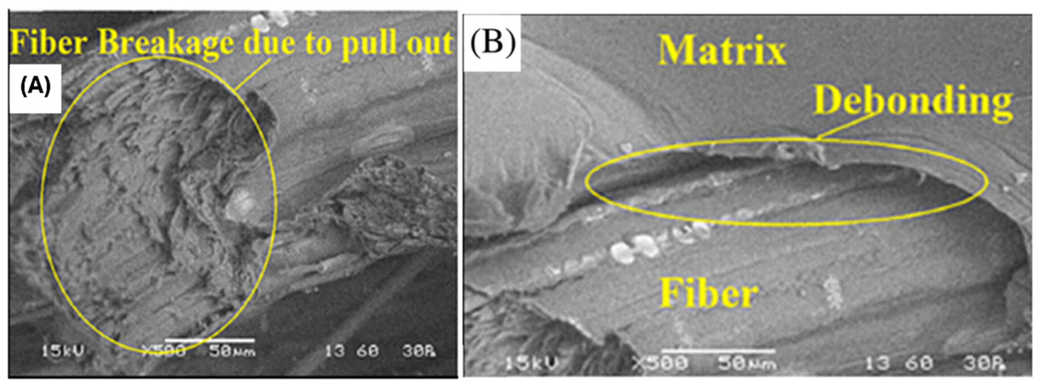
  • Fiber breakage—fracturing of reinforcing fibers under tensile or impact stress, significantly impacting the composite’s load-bearing capacity;
  • Fiber pull-out—occurs when fibers are dislodged from the matrix, usually at the interface due to weak bonding or mechanical stresses;
  • Interfacial debonding—loss of adhesion between the fibers and the ceramic matrix, compromising the load transfer and mechanical properties;
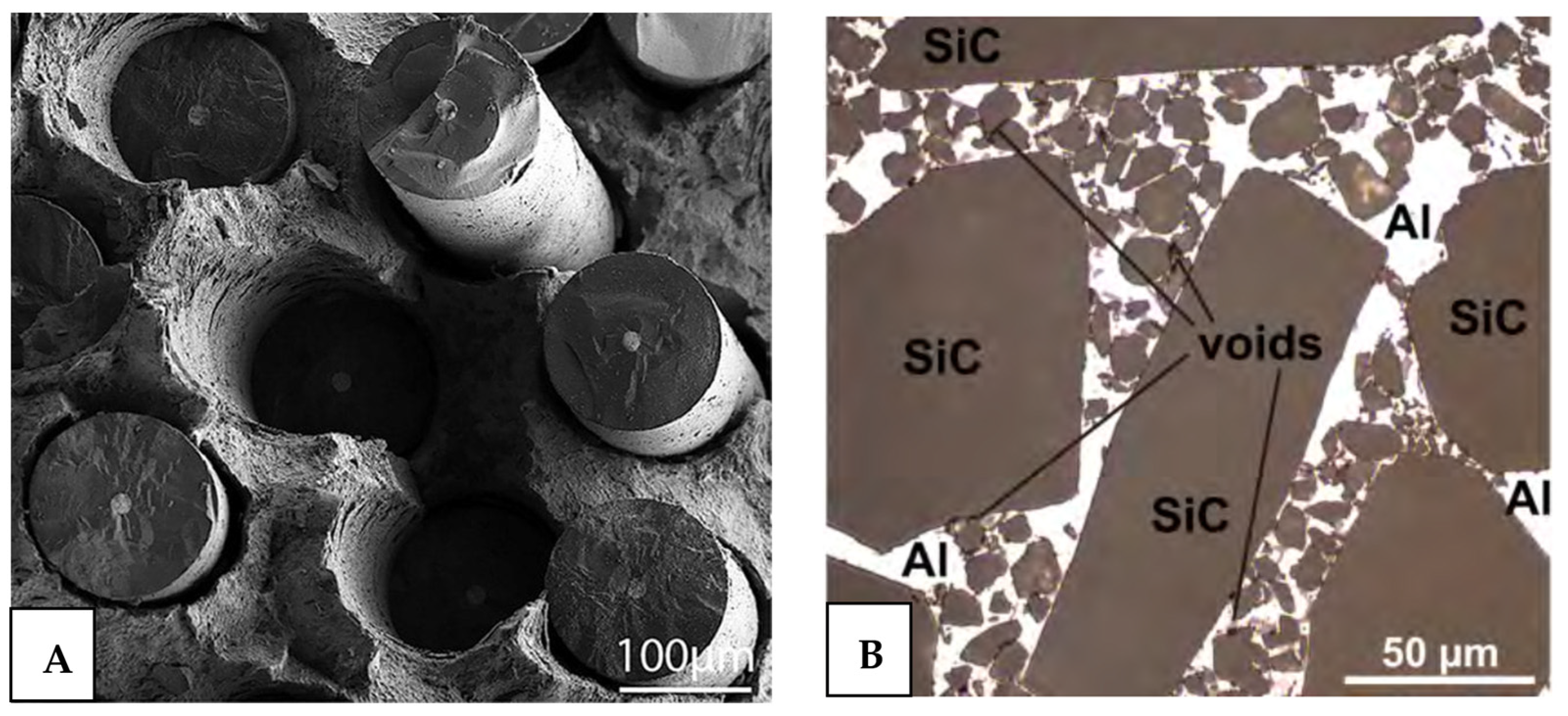
  • Porosity—the presence of voids or air pockets, usually introduced during the material processing phase, affecting the mechanical and thermal properties;
  • Oxidation damage—degradation due to chemical reactions with oxygen at high temperatures, often affecting the matrix and the fiber–matrix interface;
  • Thermal shock—rapid temperature changes causing stress concentrations and potential cracking due to differential thermal expansion;
  • Matrix degradation—chemical or structural breakdown of the matrix under environmental or thermal stress, weakening the composite;
  • Coating degradation—wear or deterioration of protective coatings, critical for protecting against environmental and thermal stresses.

4.1.2. Criteria Selection of NDT for Metal Matrix Composites

The typical damages observed in metal matrix composites are:
  • Delamination—layer separation induced by weak interfaces or disparate thermal expansion rates between the matrix and reinforcements;
  • Fiber breakage—breakage of reinforcing fibers due to mechanical overload or fatigue, crucially reducing the composite’s strength;
  • Fiber–matrix debonding—the detachment of reinforcing fibers from the metal matrix, affecting the stress distribution and overall composite performance;
  • Porosity—formation of voids during manufacturing, such as during casting or sintering, diminishing the mechanical strength and density;
  • Thermal fatigue—cracking induced by cyclic thermal stresses, particularly in components subjected to high thermal gradients;
  • Corrosion—chemical degradation of the matrix or the fiber–matrix interface, exacerbated by environmental exposure, particularly in metallic components;
  • Wear—physical degradation due to friction and mechanical interaction with other materials, affecting the surface properties and functionality;
  • Creep deformation—time-dependent deformation under mechanical stress at high temperatures, affecting long-term structural reliability;
  • Density variations—inhomogeneities in material density due to uneven distribution of the matrix and reinforcement materials;
  • Cracking—structural cracks that may develop from stress concentrations, manufacturing flaws, or external loads.

4.1.3. Criteria Selection of NDT for Polymer Matrix Composites

The typical damages observed in polymer matrix composites are:
  • Delamination—this occurs when there is a separation between layers of composite materials, typically due to weak interfaces caused by manufacturing flaws, impact, or stress concentrations. It compromises the structural integrity and load-bearing capacity of the composite;
  • Void formation—Refers to the presence of air pockets or gaps within the composite structure, often a result of improper material processing or curing. Voids can significantly weaken the mechanical properties of composites by acting as stress concentrators;
  • Fiber breakage—this defect involves the fracturing of reinforcing fibers within the composite. It can occur due to excessive mechanical loads, impact, or fatigue, leading to a reduction in the composite’s overall strength and stiffness;
  • Interfacial debonding—characterized by the loss of adhesion between the fiber and matrix, this defect disrupts the load transfer mechanisms within the composite, thereby reducing its effectiveness and mechanical performance;
  • Matrix cracking—involves cracks within the matrix component of the composite. These can develop under mechanical stresses, thermal cycling, or environmental degradation, potentially leading to more severe damage such as delamination;
  • Porosity—the presence of numerous microscopic voids within the composite material, which can decrease the density and mechanical strength, as well as alter thermal and electrical properties;
  • Resin degradation—this damage occurs due to the chemical breakdown of the matrix material under environmental factors such as UV radiation, moisture, or chemicals, affecting the durability and mechanical properties of the composite;
  • Thermal degradation—damage incurred from exposure to excessive heat that alters the physical and chemical structure of the composite matrix or the fiber–matrix interface;
  • Surface cracks—cracks that appear on the composite’s surface, often due to external mechanical forces or environmental impacts, which may propagate and lead to further internal damage;
  • Visible impact damage—includes any damage visible on the surface of the composite resulting from impact, which may include indentations, punctures, or more subtle signs like matrix crushing or fiber misalignment.

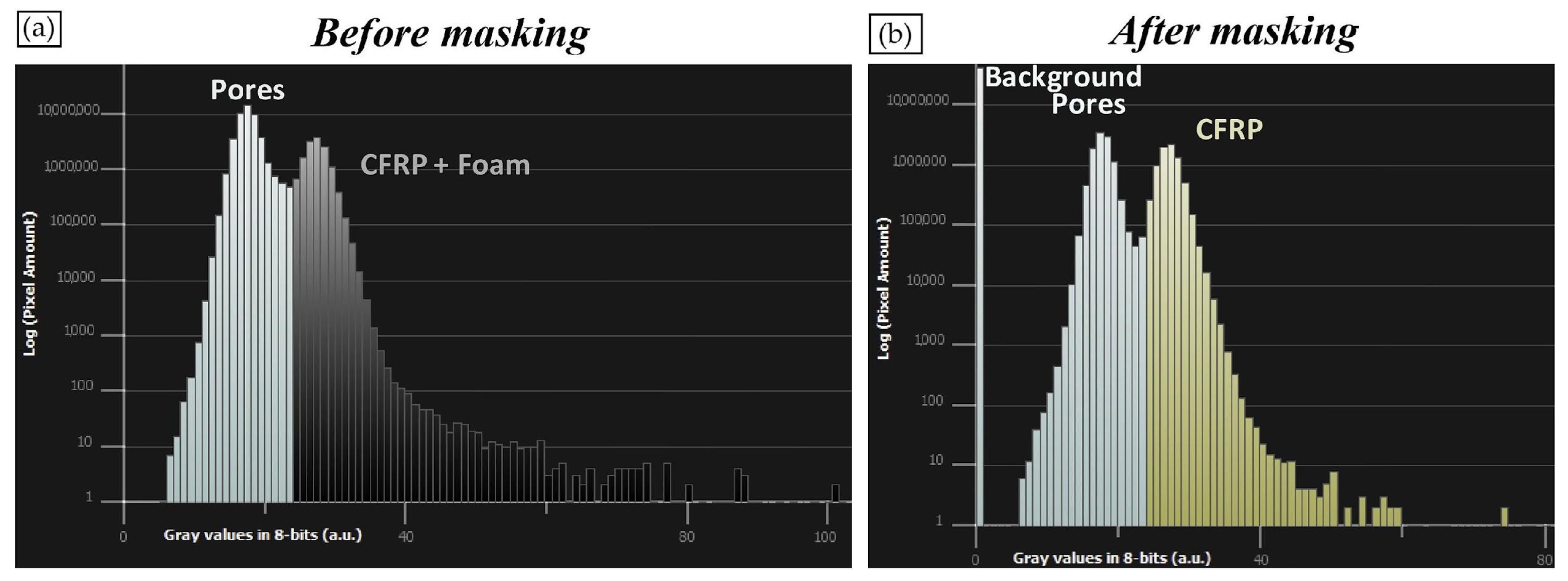
5. Ultrasonic Testing

Ultrasonic testing (UT) is an acoustic inspection method that uses elastic wave reflection and transmission within composite materials to distinguish flaws and cracks. With a wide range of frequencies between 20 kHz and 1 GHz, this technique is suited for precise applications. Non-destructive testing in the industry most frequently uses a frequency range of 0.5 to 10 MHz, though frequencies as high as 100 MHz are used, especially to detect matrix cracks. UT uses A-scan, B-scan, C-scan, and D-scan as its representation techniques [124]. The C-scan approach is especially efficient for monitoring transmission losses brought on by disbands and delamination under both low-energy and high-energy impacts [125,126,127]. Throughout ultrasonic inspections, the sound beam lines up with the reinforcement fibers’ axis to effectively characterize misalignments. Discrete reflections and transmission losses are the result of delamination and debonding from specific material depths. On the other hand, porosity results in transmission losses because it scatters ultrasonic waves instead of discrete reflections [114]. Various research works have shown that critical information for evaluating and explaining interlaminar quality can be obtained from the attenuation of waves propagating perpendicular to CFRP plies.
Methods for signal processing in the time domain and frequency domain are used to separate flaw echoes from the various reflections present in the composite. This enhances the accuracy of detection and helps localize flaws [128,129,130]. Additionally, a new signal post-processing technique has been developed [131] to address the issues related to non-parallel layers and rough surfaces in multi-material joints. Ultrasonic immersion testing, which involves coupling sound waves through a fluid medium to examine the object, is frequently used in such scenarios. This technique is efficient where there is an important gap between the air and the solid materials [132,133]. The typical frequency range used depends on the composite layer under inspection. Frequencies as low as 0.5 MHz are employed for examining and controlling structural composites up to 50 mm thick, such as glass/epoxy materials. Frequencies between 0.4 and 1.0 MHz are used to inspect 25.4 mm thick GFRP composites. Additionally, frequencies between 100 and 400 kHz, using air-coupled ultrasound, can be effective for inspecting 48 mm thick glass fiber–polyester resin composites [134]. Despite its widespread use, ultrasonic testing faces several fundamental limitations. For instance, shadowing effects can obscure larger delaminations near the surface, as these large discontinuities reflect sound and reduce visibility below the delamination. Similarly, UT encounters challenges in detecting failure and damage within non-homogeneous materials [125].
One example of the technique’s use was the identification of impact-induced damage in unidirectional CFRP. The apparatus employed in this study provided comprehensive information on the damage across the thickness of the material in a practical and effective manner [135]. An observable strong association is identified between the energy of the impacting incident and the extent of delamination. Figure 9 depicts an ultrasonic C-scan on the left, which illustrates the surface location, and a B-scan on the right, indicating the depth of damage in a specimen following a 40 J impact. Delaminations manifest at the interface of neighboring laminas. The findings from the C-Scan demonstrate that impacts result in oblong shapes emanating from the impact site, with the primary axis aligning with the fiber orientation. The overlay of these oblong delaminations forms the ellipse depicted in the left-hand image. Small discontinuities outside of the affected area stem from inherent manufacturing flaws.
Thickness damage information (depth perception of defects) is depicted through a B-scan analysis. The damage exhibits a conical morphology originating from the point of contact. It is evident that the affected region is notably more pronounced in piles adjacent to the impact location. It is imperative to highlight that, in cases of multiple delaminations, ultrasonic scanning can solely ascertain the dimensions and configuration of the nearest delamination to the surface. The interpretation of phased-array findings necessitates the manipulation of images and the evaluation of outlines to determine the envisaged delamination area. Phased-array results require image manipulation and assessment of contours to obtain the projected delamination area.
A study introduced a new developmental approach for the phased-array ultrasonic testing (PAUT) technique and described its advantages for the inspection of composite materials. The effectiveness of the proposed method for detecting flaws in composite materials is systematically compared to that of conventional single-element ultrasonic testing (SEUT). This evaluation involves a comprehensive assessment of each method’s sensitivity, accuracy, and reliability in identifying various types of defects within the composite structures. The study aims to determine the advantages and limitations of the proposed method relative to SEUT, focusing on its potential to enhance flaw detection capabilities in complex material matrices [136].
The back wall reflection of a bulk wave traveling through a GFRP composite laminate with 25 mm thickness was utilized to examine the signal properties of the PAUT and compare them with conventional SEUT performance. Figure 10 shows both the SEUT and PAUT transducers and setups. The SEUT experiments entailed the utilization of three distinct frequencies, namely 0.5, 1.0, and 1.5 MHz, to assess the attenuation of the ultrasound signals at varying frequencies. Conversely, in the PAUT experiments, a 1.5 MHz 16-element transducer was employed alongside the corresponding standard wedge.
Figure 11 illustrates the signals associated with the reflections from defects (specifically, artificially drilled holes) using SEUT and PAUT methodologies. The depth of a defect in a material during ultrasonic testing can be calculated based on the principles of wave propagation. Specifically, the equations for determining defect depth from ultrasonic reflections are derived from the fundamental relationships between time, wave velocity, and the distance traveled by the ultrasonic wave. In GFRP composite laminates, the depth of the hole can be determined through the analysis of the acquired velocity values.
In this context, time represents the duration taken for the ultrasonic wave to return to the transducer after reflecting off the defect. Velocity denotes the speed at which the ultrasonic wave propagates through the material. This velocity is a characteristic dependent upon both the material properties being inspected and the mode of the wave propagation utilized. Different materials have distinct acoustic properties that affect how sound waves propagate through them, leading to variations in velocity. The high elastic properties of the GFRP composite laminate analyzed in this study can significantly influence the speed of sound waves. This is because materials with a higher elasticity typically facilitate more efficient wave propagation, leading to increased velocity.
The results from both the SEUT and PAUT approaches closely corresponded with real-time x-ray imaging results (i.e., 11.175 mm) to validate the findings. It was noted that both the SEUT and PAUT methods exhibit the ability to identify a hole with a diameter of 0.8 mm as the minimum size and sensitivity threshold. Nonetheless, the PAUT methodology showcases a roughly 15% higher signal-to-noise ratio (SNR) for the defect signal. It is posited that, in PAUT, the lower SNR and improved signal attributes, such as heightened focusing energy, could enhance the detection of defects of smaller dimensions, necessitating further experimental study analysis.
In addition, the PAUT exhibits a more distinct and readily identifiable reflection originating from the defect, along with a superior detectable back wall reflection [Figure 11]. Conversely, the examination of the SEUT signal reveals challenges in pinpointing these reflection points due to the signal’s lack of smoothness across the transducer elements. The efficacy of advanced ultrasound for the in-field detection of delamination flaws in thick composite sections was assessed using a full matrix capture total-focusing method.

6. Acoustic Emission (AE)

The use of acoustic emission (AE) as an NDT technique is explored in this section as a diagnostic tool for monitoring the behavior of aerospace composite materials. AE is one of the NDE techniques used for investigating the initiation, progression, and characterization of various damage modes in composite materials [137]. Thus, a significant advantage of AE lies in its ability to continuously monitor the evolution of damage in composites under diverse loading conditions [138,139]. This real-time monitoring capability allows researchers to establish crucial correlations between specific AE signatures and the onset and growth of damage throughout the testing process [101,140]. For instance, studies on SiCf/SiC ceramic matrix composites have demonstrated the effectiveness of AE in pinpointing the exact stress and strain levels at which matrix cracking initiates (Figure 12). Another study showed a strong relationship between material behavior and AE signals during a mechanical test of CFRP plates. The AE could differentiate the fracture signals of 3D-reinforced and non-reinforced samples [141]. This real-time data acquisition enables proactive maintenance strategies by facilitating the detection of damage at its nascent stages.
The analysis of AE data involves the use of signal features. Frequently, the features of amplitude, energy, and frequency serve as a powerful tool for differentiating between various damage mechanisms in composite materials [101,141,142,143,144,145,146]. Research has shown that lower frequency and amplitude signals are often associated with matrix cracking, while higher frequencies might indicate delamination or fiber breakage, as shown at Figure 13. This enables researchers to have a significantly higher level of comprehension of the specific damage processes occurring within the composite material. By sorting and analyzing the signal characteristics, AE offers valuable information for material characterization and predicting potential failure modes.
Recent studies show that the field of AE is continuously evolving with the integration of advanced signal-processing techniques and machine-learning algorithms. These advancements are geared towards enhancing the accuracy of damage identification and classification based on AE data [142,143,144,145]. By leveraging these methods, researchers can distinguish between subtle damage types and refine the overall effectiveness of AE analysis, particularly for complex damage scenarios [143,146]. Machine-learning algorithms, trained on extensive datasets of AE signals and the corresponding damage mechanisms, hold promise for automating damage classification and facilitating real-time decision-making during structural health monitoring. This concept is shown at Figure 14, in which deep learning was used on the AE signal waveform to classify the matrix cracking mode.
The power of AE can be further amplified by its synergistic integration with other NDT techniques, such as DIC, infrared thermography, SEM, and X-ray computed tomography [146,147,148,149,150]. This combined approach offers a more comprehensive understanding of the damage processes in composites [18]. For instance, correlating AE signals with the observed damage features and microstructural changes visualized through DIC or SEM can provide invaluable insights into the underlying mechanisms [149]. This combined approach strengthens the overall confidence in the damage assessment by providing complementary data streams for validation.
Figure 14. Use of AI for classification of AE signal processing. Modified from [150].
Ndt 03 00003 g014
The applicability and versatility of AE are shown by its diverse range of applications across various domains within the field of composite materials. Figure 15 exhibits examples of monitoring damage in wind turbine blades for early detection and improved maintenance strategies [151], characterizing damage mechanisms during the drilling of composites to optimize manufacturing processes [152] and assessing the integrity of laminated composite structures under stress for structural health monitoring [142,143,149]. Additionally, AE has proven valuable in evaluating the influence of reinforcement type and processing conditions on the damage behavior of metal matrix composites [151,153]. Furthermore, recent advancements have seen the application of AE for detecting process-induced defects during additive manufacturing [19] and monitoring surface quality while predicting tool wear during the machining of CFRP composites [139]. The ability to detect and characterize delamination damage in CFRP laminates under tensile loading further underscores the extensive applicability of AE [154].
These diverse applications highlight the ability of AE to address a wide range of challenges in monitoring composite material structures with precision. Thus, it is possible to assert that AE stands as a reliable NDT technique for aerospace composite materials. Its exceptional capability for real-time damage monitoring and the early detection of diverse damage mechanisms proves valuable in ensuring the structural integrity and operational safety of aerospace vehicles. As research interests in advanced signal processing, machine learning, and synergistic integration with other NDE techniques increase, the potential of AE continues to expand. This continuous evolution positions AE as an NDT method for the aerospace industry allows for a deeper understanding of material behavior and may lead to the continuous monitoring of composite materials during operation, avoiding catastrophic failure in service life.

7. Radiographing Testing (RT)

Radiographic testing (RT) is a volumetric non-destructive testing technique that utilizes short-wavelength electromagnetic radiation to penetrate the internal structure of materials under examination. In this method, the component being tested is placed between the radiation source and a radiation-sensitive film or detector. Commonly used radiation sources include isotopes such as iridium-192 (Ir-192) and cobalt-60 (Co-60), with radium-226 (Ra-226) and cesium-137 (Cs-137) used less frequently [155]. Variations in absorption are due to differences in density or thickness within the component, leading to varying degrees of radiation absorption. Thicker and denser areas block more X-rays or gamma rays, while thinner areas allow more radiation to pass through. The transmitted radiation is captured by the film, plate, or photo-sensitive paper, forming a shadowgraph. Darker areas on the image indicate higher exposure levels, corresponding to increased radiation intensity, whereas lighter areas indicate lower exposure and intensity. Radiographic testing allows for the detailed visualization of defects and internal structures without a prior arrangement of the components being tested, as highlighted by the International Atomic Energy Agency [156].
It is a highly sensitive method that is capable of inspecting hidden areas without direct access, unlike ultra-sonic testing and, despite its utility, has several limitations. These include the potential radiation hazard associated with older equipment, the high costs of the necessary machinery, and the time-consuming nature of the process due to prolonged exposure times. Furthermore, RT cannot assess the depth of discontinuities and requires access to both sides of the component for effective testing. If the orientation of a flaw aligns with the path of radiation, RT may not detect the defect. Additionally, certain radioactive isotopes struggle to penetrate polymer matrix composite materials. RT is also ineffective at identifying delamination because it relies on density changes, which are not present in delaminated areas. Consequently, RT is not commonly used for aircraft inspections. However, these limitations can be mitigated by utilizing an advanced form of conventional RT known as X-ray CT [157].
This technique provides high-resolution 3D images of the structure being inspected through a two-step process. The initial step in X-ray computed tomography involves acquiring 2D cross-sectional images of the structure under investigation, which are then reconstructed into a 3D image. This generation of 2D cross-sections is typically achieved through scanning, where the tested element is either rotated on a rotary table while the X-ray source and detector remain fixed, or the element is kept stationary while the source–detector pair rotates around it. A collimated X-ray beam penetrates the element and is captured by an array of detectors on the opposing side. One of the key advantages of X-ray CT is its ability to provide volumetric representations of the tested element. Advanced techniques and equipment, such as nanoCT (nCT), microCT (μCT), and industrial CT (ICT), enable high-resolution volumetric scans that facilitate the detection of meso-scale damage and allow for the assessment of a component’s internal structure at the nano-scale. The efficacy of these scans is well-documented in the scientific literature [158,159]. Despite its advantages, the widespread adoption of X-ray CT is hindered by the high cost of inspection and the constraints of laboratory conditions. Additionally, the absence of standardized testing procedures and the lack of result traceability are concerns frequently highlighted in the literature [160]. X-ray CT has demonstrated its value in assessing delamination in materials such as carbon fiber-reinforced polymer laminates and woven glass-reinforced polyamides [158,159]. It is also effective in the identification of casting defects in aluminum components [161].
The accuracy and reliability of X-ray CT have been established in the aerospace industry for inspecting critical components, such as aircraft wings, turbine blades, manifolds, and cast aluminum cylinders [158,162]. A study proposed a versatile and non-destructive inspection approach to evaluate the composition of various aircraft components made from carbon fiber-reinforced polymers encompassing both sandwich configurations. Among the array of non-destructive testing techniques, X-ray computed tomography is recognized as a flexible and precise method for detecting porosity in the CFRP composite elements of sandwich structures [163].
Specifically, an aircraft composite component with a specific structure was examined, namely a sandwich component composed of outer skins constructed from prepreg resin reinforced with TOREY-type carbon fibers and an AIREX R82.60 foam core with a known density. This component was analyzed using X-ray CT to investigate the volumetric distribution of identified pores, facilitating interactive 3D exploration and visual porosity analysis through a comprehensive 3D volume rendering of the analyzed composite.
The accuracy of the porosity measurements for the sandwich-structured composite was indirectly determined by comparing the foam porosity, as measured by X-ray CT, with the value specified in the foam datasheet.
The images presented in Figure 16a depict the plain arrangement of the carbon fibers in the initial ply relative to the surface of the panel. Figure 16b shows images of the panel’s cross-section, highlighting the two outer skins, each consisting of two plies, with a foam core centrally positioned between them. The overall thickness of the sample is approximately 3.50 mm, with the foam layer measuring around 2.8 mm and the two external skins, composed of CFRP, each being roughly 0.35 mm thick. Optical microscopy images of the panel section reveal strong adhesion between the central foam layer and the surfaces of the two outer skins, with no visible pores at the skin interface due to the sandwich composite manufacturing process. The porosity of the two outer skins of the composite sandwich panel was assessed using X-ray computed tomography at resolutions of 5 μm and 15 μm, following the detailed experimental parameters defined in this work. The choice of these two resolutions was guided by the initial X-ray CT configuration that was necessary to optimize the analysis conditions concerning the acquisition time–resolution ratio. Additionally, a preliminary material assessment via optical microscopy indicated the absence of discernible submillimeter pores on the external panel surfaces. To exclusively evaluate the porosity of the skins, a mask was applied after image acquisition and 3D sample reconstruction to exclude the foam with known density from the pore analysis, thereby isolating the two outer skins under investigation. This mask was readily delineated by highlighting the distinct boundary between the foam and the skins using an analysis software denominated Avizo 8 Fire Edition of Visualization Sciences Group (FEI Company). Figure 17 shows the 3D rendering of the complete sample before and after masking, where the foam was excluded, leaving two monolithic skins for porosity analysis.
After masking the foam, the sample structure was simplified into two monolithic panels representing the skins. Subsequently, X-ray computed tomography was employed to assess their porosity levels. This masking procedure facilitated the uniform representation of the total foam volume, associating it with the background (depicted as the black segment in the grayscale histogram), thus aiding its identification during the void-labeling stage and its exclusion from the overall pores volume quantification.
The grayscale histograms, before and after foam masking, are presented in Figure 18. In the grayscale histogram prior to foam masking, the two peaks represent distinct densities within the composite. The leftmost peak corresponds to the pores present in both the skins and the foam, while the rightmost peak corresponds to the CFRP of the skins and the foam, both composed of carbon atoms. Following the foam masking process, a new leftmost peak appears, representing the background associated with the masked foam. Consequently, the designated range of grayscale values from 0 to 24 includes both the background and the pores. A visual analysis of the grayscale histogram is shown in Figure 18.
By employing X-ray CT, this study provides an in-depth analysis of the volumetric distribution of pores in sandwich-structured CFRP laminate as an aircraft component, offering a comprehensive 3D exploration and visualization of these materials. The approach validates the precision of X-ray CT in detecting porosity by comparing its results with standard methods, such as acid digestion and datasheet values. The research highlights the importance of precise CT configurations, including resolution choices guided by initial assessments to ensure accurate pore analysis. The use of masking techniques to isolate the composite skins underscores the sophistication of the methodology in achieving a focused evaluation. This study not only confirms the strong adhesion between composite layers, as evidenced by the absence of visible pores at the interfaces but also emphasizes the capability of CT imaging to reveal distinct density variations within composite structures. Such insights are crucial for advancing the quality control and reliability assessment of composite materials in aerospace applications, demonstrating X-ray CTs.
Another recent detailed experimental numerical study was predominantly focused on the prediction (visualization) of the impact damage behavior caused by a low-velocity impact on a CFRP laminate. In this, an X-ray CT and an ultrasonic C-scan method were used to evaluate the impact-induced damage in a CFRP composite laminate that has been exposed to a low-velocity impact through a precisely defined drop-weight test. One of the objectives was to assess the capability of both methods in detecting damage in the CFRP test specimen following impact. Consequently, another objective is to delineate the advantages and limitations of the two techniques. Furthermore, a third objective is to juxtapose the empirical findings with those anticipated through a recent 3D, elastic–plastic, FEA-based computational damage model, as proposed in the literature [164]. The damage maps derived from the experimental techniques of C-scan and X-ray computed tomography, as well as from the predictions of numerical simulations, are shown in Figure 19 for the delamination footprint along with the associated damage area denoted as ‘DA’. Figure 19a depicts the delaminations within the composite material consistently across its depth, as illustrated in the X-ray CT scan findings. This visualization further validates the observation that the delaminations exhibit a growth pattern towards the underlying plies at each interface. In Figure 19b, it is evident from the X-ray CT scan findings that the observed striations and other characteristics clearly signify the growth of delaminations in the direction of the plies located below each ply interface. For both NDT techniques and numerical predictions, the delaminations appear in comparable shapes and positions in both inspection methods. However, as expected, the X-ray CT scan provides significantly higher detail and resolution than the C-scan.
Figure 20 compares the numerical prediction of damage and the experimental recording of damage for the X-ray CT scan showing delamination at each interface between differently oriented plies across the thickness of the composite panel for the current CFRP layup of [45°/−45°/0°/90°/0°/45°/45°]. In Figure 20a, the numerical model predicts that delaminations tend to propagate in the direction of the fibers existing beneath the interface. In comparison, the experimental X-ray CT scan delamination mapping is presented in Figure 20b and presents the experimental X-ray CT scan, which largely conforms to the simulation in terms of the configuration and location of the interlaminar damage. However, the X-ray CT scan appears to underestimate the spatial extent of the delaminations, particularly in the lateral direction.
The delaminations identified in both methods have similar shapes and positions, although, as expected, the X-ray CT scan provides significantly greater detail and resolution compared to the C-scan. The X-ray computed tomography technique offers a more detailed depiction of the damage but may fail to capture the full lateral spread of delaminations, especially when compared to the C-scan. The C-scan exhibits greater sensitivity to smaller delamination cracks, revealing a more comprehensive scope of the damage.

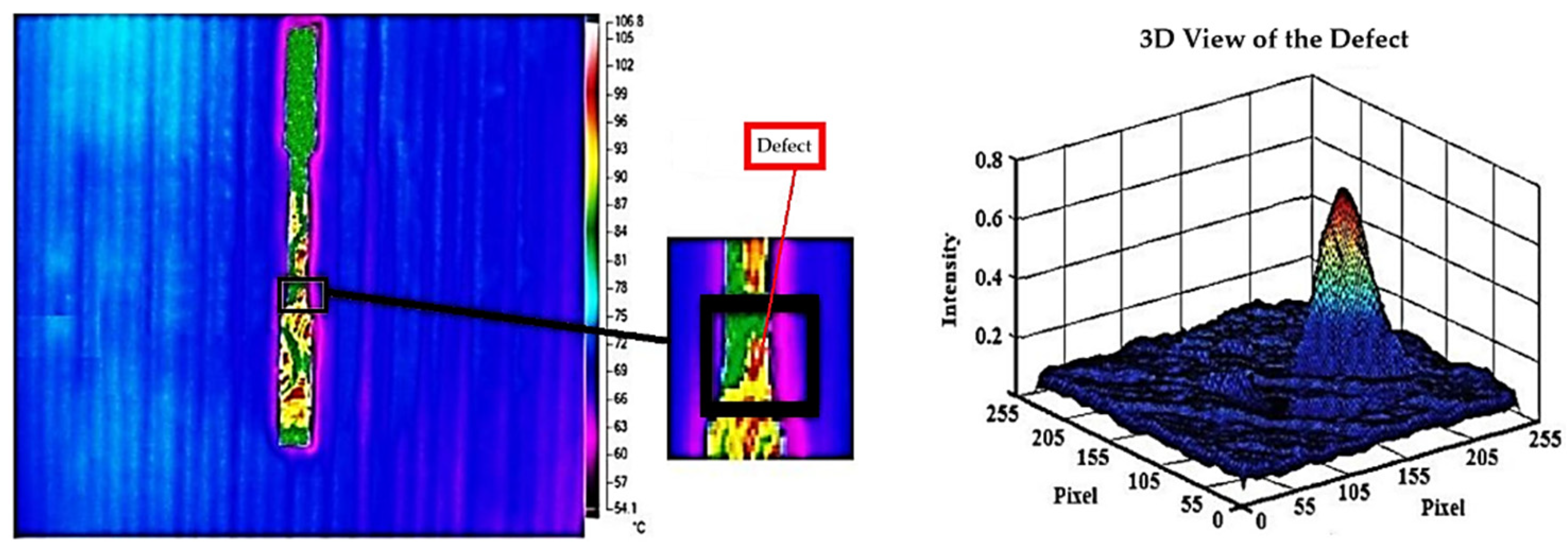
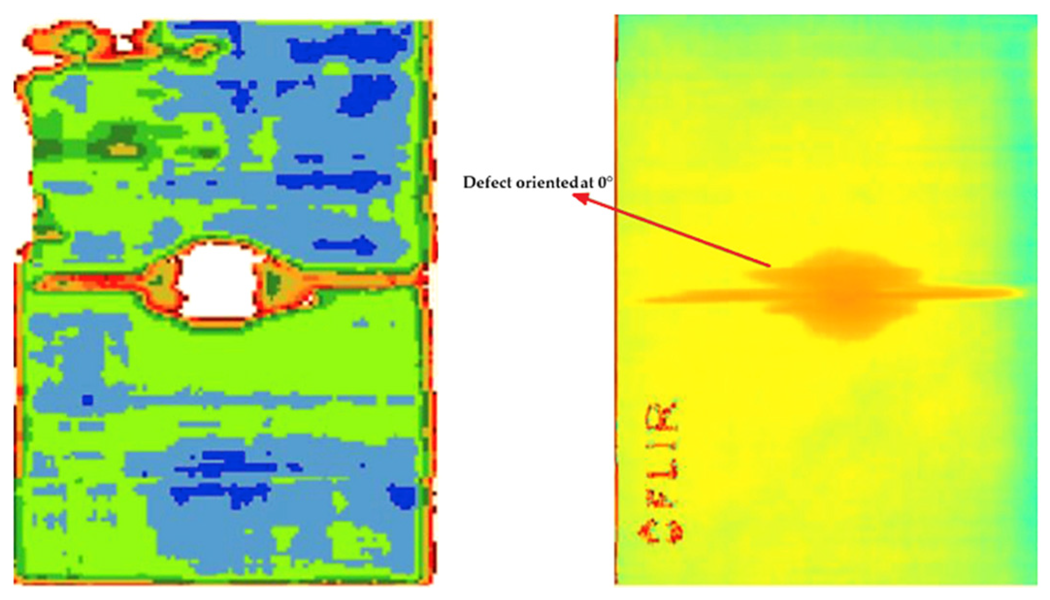
8. Infrared Thermography

Among NDT techniques, infrared thermography (IRT) offers a distinct advantage. Unlike many NDT methods, it excels at visualizing the surface temperature distribution of an object or component. This unique capability allows for the rapid and real-time scanning of large areas [165]. Unlike traditional NDT, which directly detects internal flaws, IRT leverages the principle that an object’s emitted infrared radiation directly correlates with its surface temperature [166]. The IRT technique can be categorized into passive or active types. Temperature gradients are utilized to non-destructively detect material damage. Passive infrared thermography relies on the inherent thermal emissions of the object under examination. Variations in thermal signatures can indicate irregularities, which may result from structural defects, damage due to loading, or friction between moving parts, for example [167].
Conversely, active infrared thermography employs external stimulation—an input source—to induce thermal contrasts within the material. This external heat can be applied using various methods, such as optical (e.g., lasers, lamps), mechanical (e.g., ultrasonic waves), or electromagnetic techniques. By creating temperature gradients, active thermography enhances the detection of subsurface flaws that an IR camera then records. This approach provides a controlled mechanism for introducing energy into the material, enabling the detection of deeper or more subtle defects that passive techniques might overlook. Active thermography is adaptable to different defect types and materials, making it a versatile tool for conducting quick inspections over large areas without compromising material integrity—a relevant requirement in industries such as aerospace [168].
A pioneering study investigated the efficacy of the IRT technique for defect detection in high-temperature structural composite materials commonly employed in the aerospace sector, namely two CMCs, an MMC, and a PMC. The research explored the influence of defect size and depth on detectability using active IRT with flash lamps as the external heat source. The objective was to establish the limitations of IRT for defect detection based on defect depth and size. The findings revealed a material dependence on IRT’s defect detection capabilities, as shown in Table 9. Due to the rapid thermal diffusivity of the composites, the technique excelled at identifying shallow defects. For CMCs, thermography effectively detected shallow to mid-depth defects, but its sensitivity diminished for deeper anomalies. Similarly, IRT demonstrated promising results for surface and near-surface defects in MMCs, while deeper defects posed limitations. Notably, PMC materials presented the greatest challenge due to their lower thermal diffusivity, which significantly decreased the possibility of the detection of deeper defects. These results show how depth and thermal characteristics influence IRT’s detection limits [169].
The research also compared thermographic imaging with established NDT techniques like ultrasonics and radiography. While radiography exhibited high detection efficacy across all material samples, thermography offered a non-contact and rapid assessment method, which is potentially advantageous in specific operational scenarios.
The infrared thermography technique also has a significant role in the quality control of parts, especially for MMCs and CMCs, as these still-developing manufacturing processes are susceptible to specific defects. The employability of active infrared thermography for the quality control of a high-performance Al-MMC component was the goal of an investigation [170]. The focus was on ensuring a lightweight, high-strength component, which highlights the increasing demand for such materials industrially. The preliminary findings from a quality assessment of a steering knuckle component fabricated from cast Al Si7Mg0.3 + nSiC used IRT to spot the defect and computed tomography to verify in detail.
The results indicate that IRT excels at identifying surface defects and porosities within the MMC component. As expected, the tomography offered a more comprehensive analysis of the internal structure, confirming and elaborating on the presence and distribution of porosities initially detected by IRT. This combined approach not only facilitates the detection of manufacturing defects but also ensures adherence to the stringent quality standards demanded by high-performance applications.
The use of passive IRT also presents a valuable tool for monitoring material behavior during mechanical testing. The mechanisms of heat generation during material deformation are complex, involving material and testing characteristics. Material type significantly influences internal friction and dislocation movement, while deformation rate and extent also exert a substantial impact on heat generation. A study investigated the application of passive IRT for monitoring the tensile test of a SiC-reinforced aluminum metal matrix composite. The primary objective was to visualize the various stages of the deformation process using IRT. The findings demonstrated the effectiveness of infrared thermography in the characterization of the deformation behavior of Al-SiC MMCs. The captured infrared images during tensile tests revealed significant correlations between temperature rise, deformation behavior, and the ultimate strength of the materials. The results indicated a significant relationship between the rate of temperature rise and the mechanical behavior under tensile loading [171].
Infrared thermography was used to investigate the fatigue behavior of SiC/BMAS glass–ceramic matrix composites, a material employed in aerospace applications. The cross-ply laminated CMCs were mechanically tested at ambient temperatures, with IRT integrated for real-time monitoring of temperature variations generated from mechanical loading (Figure 21). The lock-in thermography was employed to facilitate a rapid and precise assessment of the composites’ fatigue limits by synchronized monitoring of the infrared radiation emitted during cyclic loading. As shown in Figure 21, the IRT lock-in exhibited crack propagation through time. The temperature changes associated with crack development were captured by the IRT camera, allowing researchers to map crack progression, and this allowed for the estimation of the remaining useful life of the composite. Finally, analysis of thermal signatures from the thermographic data provided an understanding of the behavior of the internal state of the material during testing. The analysis revealed relevant damage points and the initiation of material failure at the tip, exhibiting the detailed thermal patterns observed in lock-in thermography images corresponding to various stages of material fatigue. By applying a more advanced use of the IRT technique, the study highlights its effectiveness in investigating material integrity and predicting potential failure points before catastrophic events [172].
A study utilized active pulsed infrared thermography (APIRT) to assess the integrity and quality of aluminum–silicon carbide (Al-SiC) composites manufactured via stir casting. This method proved particularly effective in detecting subsurface defects up to a depth of 4 mm. APIRT’s ability to identify smaller defects was notably superior when compared to other NDT techniques employed in the investigation. Regarding scanning electron microscopy, it provided a high-resolution surface analysis. Meanwhile, liquid penetrant testing (LPT) detected surface defects, and radiography/ultrasonic testing assessed internal integrity. But, none offered the combined depth, accuracy, and sensitivity toward small defects that APIRT delivers, as shown in Figure 22 [173].
A comparison between pulsed thermography testing (PTT) and ultrasonic testing was proposed to evaluate the damage caused by impact on CFRP parts [174]. The investigation employed varying sample thicknesses and impact energies to induce different damage levels. A probability of detection (PoD) analysis served as the primary quantitative measure, in which the PPT demonstrated a clear advantage in detecting smaller defects compared to UT. As shown in Figure 23, the PTT was also able to identify the defect, regardless of defect orientation. Specifically, PTT achieved a higher probability of detection (a90/95 values) for smaller defects at a 90% confidence level. However, a current limitation of PTT lies in its ability to detect deeper damage within the structure. While this study employed PPT and succeeded in detecting and quantifying the extent of damage, further research is required to enhance its capability for deep-seated defect detection. These findings support the advancement of IRT as an effective method for near-surface damage detection in aerospace structures.
The impact resistance of a proposed hybrid composite material from Kevlar/flax reinforcement with epoxy resin employed infrared thermography to monitor the test and evaluate the extent of the damage post-testing [Figure 24]. The high-speed IRT camera system captured thermal data during low-velocity impact, enabling real-time mapping of the damage progression. The detailed temperature field generated by IRT provided valuable insights into internal damage mechanisms, which are often invisible through visual inspection alone. This technique proved particularly effective in identifying delaminations and fiber breakages within the composite structure [175].
To further evaluate the performance of a composite wing rib component under impact damage, a study utilized ultrasonic stimulation to induce an IRT response [176]. This enabled a comprehensive analysis of the damage sustained by the part. IRT demonstrated high sensitivity, effectively detecting not only the presence of defects but also their nature and extent. The study further employed a local binary fitting (LBF) model to enhance the segmentation of defect edges within the thermal images. Notably, the research addressed the challenge of discontinuous defects, a common characteristic in multilayered composite materials. This was achieved by implementing algorithms that merge defects across both the temporal and spatial domains (Figure 25), ultimately improving the clarity and usability of the thermal imaging data. The study also included the development of methods for defect reconstruction within the thermal images, which allowed for a more detailed and accurate evaluation of the damage within the composite material.
An innovative study aimed to measure coating thickness using active IRT, showing another use of the NDT technique [177]. The investigation focused on thermally sprayed coatings deposited on steel substrates with varying thicknesses ranging from 0.1 mm to 1 mm [Figure 26]. The results demonstrated the effectiveness of IRT in achieving rapid and accurate thickness measurements. The IRT-derived values displayed a high degree of accuracy, deviating from micrometric measurements by a standard deviation of only 40 μm. Additionally, the study introduced a novel quantitative evaluation method based on the concept of apparent effusivity. This method utilizes a threshold value of apparent effusivity that is specific to the particular coating–substrate combination.
Emerging as a powerful tool in non-destructive testing, infrared thermography (IRT) offers significant advantages for evaluating damage and defects in high-cost composite materials in aerospace engineering. Furthermore, ongoing advancements in IRT techniques, its synergy with other NDT methods, and the incorporation of artificial intelligence position IRT as a key tool for the efficient detection of near-surface damage in engineering and materials science.

9. Shearography and Holography in NDT

Among the above-mentioned methods, holography techniques, considered as a non-conventional approach to inspection, have demonstrated great potential in the detection of various flaws that present particularly in composite materials (composites). Optical techniques are considered the most appealing method for non-destructive evaluation due to their non-contact nature, as well as their capabilities, including rapid inspection speed and real-time digital image processing for automating the defect identification process. (the damage identification procedure). One of the optical techniques employed in materials testing is known as shearography testing.
Shearography, also referred to as the laser-based optical method [178] is a nondestructive evaluation (NDE) technique that is commonly employed for the purpose of detecting failures. To implement image shearing in digital shearography, it is necessary to position a shearing apparatus in the camera’s field of view. One of the optical techniques employed in NDE is shearography testing. Shearography, also referred to as speckle-pattern shearing interferometry (SPSI), is a real-time method extensively applied for the purpose of detecting failures. The phenomenon is rooted in the generation of a fringe pattern through coherent laser illumination, whereby distinct path lengths give rise to interference among coherent light waves. The implementation of the shearography technique in composite materials has been elucidated in various research endeavors. Okafor et al., [179] employed a variety of methodologies to evaluate high-velocity impact on sophisticated composite panels. They used shearograms and UT C-scan to determine the flaw location and to show how AE variable parameters (variables) correlate with one another. This interferometric method, which is called stereography, was created to overcome some of holography’s limitations. Several important benefits of this technique ensure direct measurement of displacement gradients and surface strains. Since flaws cause displacement gradient concentrations, it is simpler to correlate flaws with displacement gradients rather than displacement damages.
Shearography is extensively utilized within the field of aeronautics to assess composite components. When employed within the aerospace industry, Shearography presents numerous benefits, including rapidity and live tracking of sizable composite panels [180,181]. Due to these significant advantages, shearography is presently employed for NDT on a range of aircraft, such as the Airbus, A380, the Boeing, Dreamliner, the Cessna, Cessna Citation X, the Lockheed Martin, F-22 and F-35 JSF, and the NASA space shuttle [182,183]. Shearography is predominantly utilized for the purpose of identifying debonding or the onset of delamination, since stress concentrations in the vicinity of a specific imperfection escalate the risk of failure in composite materials [134,184,185,186,187,188]. Nevertheless, shearography has some significant drawbacks, including the challenge of characterizing damage mechanisms that range from microscopic to mesoscopic, such as matrix cracking, fiber breakage, and matrix–fiber debonding. Moreover, it is difficult to apply in industrial operations due to its sensitivity to environmental disturbances [189].
Researchers, including Lomov et al. [190], employed digital shearography to measure the strain in textile composites. They achieved enhanced resolution of the strain field in elastic deformation and detected damage initiation using linear regression. Additionally, their work included the validation of meso-FE models for woven (carbon–epoxy and glass–polypropylene) and braided (carbon–epoxy) composites. Yoon et al. [191] and Lee et al. [185] conducted analyses on the mechanical properties and material characteristics of fabric composites through the employment of digital shearography. Hung et al. focused on the examination of the residual stress in composite materials by using shearography. Shearography has various applications, including the analysis of 3D geometries, vibrations, and leak detection. Gryzagoridis and Findeis [192], as well as Newman [193], have documented the diverse functionalities of shearography in detecting and analyzing disbonds and delaminations within slender CFRP laminates. Furthermore, Gregory [194] has highlighted additional capabilities, such as expedited inspection times and cost efficiency.
The development of a simultaneous dual-resolution digital holography system was the main innovation of the research conducted by Zheng et al. [195]. This innovation allows for the capability of conducting current measurements using both wide and narrow fields of view and the observation of complete-field deformations alongside localized details, specifically in regions of strain concentration. To authenticate the operational integrity of the digital holography system developed in this study, a non-destructive testing procedure was executed on a circular aluminum plate containing a diminutive flaw. The circular plate possessed a dimension of 10 mm thickness and was securely positioned in a sealed chamber with a diameter of 150 mm. This sealed chamber was linked to a vacuum system to apply pressure on the circular plate.
The anomaly manifested as a diminutive circular shape measuring 8 mm in diameter and 0.6 mm in thickness upon the surface. An applied pressure differential of 10 KPa facilitated the identification of said anomaly, with the outcomes depicted in Figure 27. Analysis of the image reveals that the comprehensive area is observable through a wide field of vision; nonetheless, as indicated in Figure 27a, the minute anomaly could potentially go unnoticed. Nevertheless, meticulous scrutiny under a narrow field of vision, illustrated in Figure 27b, reveals the presence of these minor anomalies.
A further deformation assessment was conducted utilizing this setup with an immaculate square aluminum plate. The plate was secured on all sides by screws, measuring 100 × 100 mm. The phase map for narrow and wide fields of view is depicted in Figure 28. An external force was exerted at the midpoint of the plate through a screw micrometer. In the expansive field of vision, the phase map depicted in Figure 28a exhibited significant ambiguity due to the substantial load magnitude leading to overly dense fringes, rendering it unsuitable for deformation calculations. Conversely, within the limited field of view, the phase map illustrated in Figure 28b displayed enhanced clarity, enabling its utility in deformation calculations.
The newly created system is promising and proves advantageous for assessing deformations and strains, as well as for non-destructive evaluation, particularly in scenarios involving non-repetitive loading.
As technological advancements progress, novel technologies have been implemented in shearography, including the utilization of the spatial light modulator [196] to enhance the overall system performance. In the conventional shearography approach, the level of shearing is adjusted mechanically, and the piezoelectric ceramics responsible for introducing the phase shift often exhibit nonlinearity, resulting in challenging random errors to mitigate. Recent studies have introduced innovative methodologies to present new opportunities for expanding the scope of digital shearography applications. In a study conducted by Sun et al. (2018), a novel shearographic system, incorporating a spatial light modulator [197,198], was proposed, enabling precise manipulation of phase and shearing levels, thereby enhancing the elimination of nonlinear random errors with increased efficacy. The shearography system, featuring a spatial light modulator, is illustrated in Figure 29a, with corresponding experimental outcomes depicted in Figure 29b,c. The high quality of the phase diagram indicates the system’s capability of fulfilling NDT requirements through meticulous control.

10. Digital Image Correlation (DIC) and Optical Methods

Digital image correlation (DIC) is a non-contact image-based methodology used for assessing surface shape, deformation, and strain [199,200] and originated in the 1980s [201]. Initially, the digital speckle image focused on the examination of one-dimensional field measurements, tracking light intensity pre- and post-deformation. By employing a peak cross-correlation function, it can determine object displacement. DIC relies on grey-value digital images to delineate both the contour and displacements of a loaded object in three dimensions, expanding the one-dimensional approach to enhance precision in measurements [202].
In a previous study, DIC was employed to evaluate displacements and deformations in wind turbine blades [203]. The results allowed for several crucial material properties to be derived, including ultimate tensile strength, ultimate compressive strength, Poisson’s ratio, and the initial elastic moduli for both tension and compression. Furthermore, the non-contact nature of DIC is beneficial for specimens that are difficult to attach. For instance, a study showed the use of DIC to assess six fiber-reinforced polymers (FRP) grids subjected to direct tensile loading [204], where they applied open-source DIC Ncorr (version 1.14.0.0) software for analyzing images [205]. The results obtained from DIC, including the Young’s modulus, were compared with data from conventional strain gauges, showing discrepancies of less than 5%. An 18 MP camera captured images every 2 s during the tensile testing, with adjustments made to enhance spatial resolution and strain accuracy due to the narrow grid width. The study suggested utilizing solely the linear average value of Young’s modulus and cautioned against directly using DIC strain map analysis due to its high variability, influenced by factors such as lighting changes, bias errors, external vibrations, and camera movements.
Another study investigated how the type of confinement material affects the overall behavior and strain distribution in concrete specimens confined with FRP [206]. The experiment tested ten confined and unconfined specimens to evaluate different types of strains. As axial loads were applied, researchers monitored the progression of axial, lateral, and Von Mises strains, along with post-peak strain softening behavior. DIC data were validated using a direct-contact measuring device. The results revealed that the expansion of the shear zone in unconfined concrete was more localized compared to the FRP-confined sample. Furthermore, DIC was found to provide a more precise evaluation of the entire field in contrast to contact methodologies. Other applications of DIC in civil engineering include a variety of studies, such as composite additive manufacturing of large-scale structures [207], tensile testing of CFRP [208], characterization of bond-slip behavior in CFRP-steel composite members [209], development of bond-slip models [210], investigation of FRP–masonry bonding [211], and analysis of dynamic response in composite sandwich structures under air-blast loading [212].
Digital image correlation is largely applied in aerospace sectors. Figure 30 shows the use of DIC to perform strain and deformation analysis during full-scale aircraft impact experiments at the NASA Langley Research Center [213]. These experiments were conducted on three Cesna 172 General Aviation aircraft models, where strain and deformation profiles were immediately generated following structural failure. This analysis provided valuable insights into the severity of the impact and the localization of damage. This involved the utilization of a random speckle pattern on the fuselage of the aircraft and the observation of lateral deformation resulting from a crash event.
DIC is increasingly used for the micro-scale analysis of composites, effectively capturing mean strain and microstructural heterogeneity [215]. Its versatility is evident in studies involving temperature variations. For instance, study of the thermal sensitivity of polymer composites using DIC revealed that elevated temperatures significantly affect the axial and shear properties of polymer composites [216]
DIC is also instrumental in validating computational models [217,218]. By comparing detailed strain maps from DIC with finite-element predictions, researchers can refine and validate these models, leading to a deeper understanding of the mechanical behavior of composites, particularly regarding anisotropic properties influenced by fiber orientations. Additionally, DIC excels at providing insights into the damage mechanisms of composites. It has been used to analyze strain fields in fiber-reinforced composites under complex loading, allowing for the identification of stress concentrations and the investigation of non-linear strain responses [219].
Furthermore, DIC’s integration with acoustic emission (AE) techniques improves damage detection in ceramic matrix composites, providing insights into matrix crack initiation and propagation [220]. Its ability to capture intricate strain variations at the sub-fiber tow level offers critical insights into crack growth, surpassing some traditional methods [221]. DIC can achieve a strain measurement precision of 10−4 or better, especially when optimal speckle application techniques are employed. Figure 31 shows how this dual-technique approach not only confirms the locations of physical damage with high precision but also helps in visualizing the non-uniform distribution of the mechanical stresses that lead to material failure. The results demonstrate that combining DIC and AE allows for a more robust analysis of the dynamic failure processes, thereby contributing to the development of better predictive models and enhancing the design and reliability of ceramic matrix composites in aerospace and other high-stress applications.
In addition, Figure 32 illustrates the application of DIC. Panel (a) uses displacement contours to effectively depict the strain distribution within the composite. Panel (b) presents an optical micrograph of the sectioned area, highlighting a specific region for detailed examination. Panels (c) and (d) display high-resolution electron micrographs of this region, revealing fiber breaks and matrix cracks at a microscopic scale, with blue and red arrows indicating the breaks and cracks, respectively. The microscopic images aligned with DIC results analyses allowed for a comprehensive understanding of the overall strain patterns and the underlying microstructural damage mechanisms within the composite. By understanding how strains localize and how cracks initiate and propagate, researchers can develop more robust composite materials for demanding applications.
Despite its strengths, DIC faces challenges. Limitations in experimental setups and the need for fine speckle patterns can hinder the detection of localized strains. Effective DIC application relies on a careful selection of camera fields of view (FoVs) and precise camera positioning. Moreover, variability in surface patterns can impact measurement accuracy, highlighting the importance of uniform speckle application. While the integration of novel sensors, such as fiber Bragg grating (FBG) sensors, promises enhanced monitoring capabilities [222,223], challenges remain in measuring the stress concentrations around embedded sensors [224]. Addressing these limitations is crucial for optimizing the design and ensuring the structural integrity of composite materials in aerospace engineering.

11. Advanced NDT Techniques and Future of NDT of Structural Composites

11.1. Developing NDT Techniques

Numerous NDT methodologies retain the capacity for enhancement to effectively address the challenges faced. These enhancements may be classified into three distinct categories: enhancements and advancements of individual techniques, integration of hybrid methodologies, and the utilization of machine learning.
One of the primary challenges associated with composites lies in the inability to accurately assess the quality or durability of adhesive bonds, primarily due to the unique characteristics of the adhesive material and the limited knowledge in this area. This is a key reason why NDT plays a crucial role in this context. Throughout the manufacturing process, it is common practice to evaluate the reference composites and their bonding through destructive techniques, various sample analyses, and computer simulations.
A study showed that comparing the adhesive strength obtained from non-destructive methods to conventional destructive testing presents challenges, as each method assesses the bonded structure differently. A promising advancement in this field is the use of laser shockwave technology, which generates shockwaves through laser-induced plasma, allowing for a bond quality assessment throughout the material thickness. By controlling the intensity of the shockwave, the strength of the adhesive bond can be evaluated. If the bond lacks sufficient strength, it fractures. If it meets the required threshold, it remains intact [225]. Regarding this NDT method, another study indicates that the shockwave impact remains within the elastic range, preserving the material’s properties. This approach delivers similar results. In addition to assessing bond quality, it can detect defects that conventional NDT techniques were unable to identify [226]. Further research is required to fully develop this technology for practical use.
In addition to advancements in techniques, enhancements can also be made to existing NDT methods. The challenging aspect of IRT lies in its ability to detect heterogeneity and its restricted capability in assessing depth. These limitations portray IRT difficulty for defect detection in CFRP laminates due to the minimal contrast in thermal properties among constituent materials, the thin epoxy layer, and the bonded interface’s depth. An investigation proposed a novel approach by introducing a new composite material for joints to amplify thermal gradients between bonded components and flaws, akin to incorporating marker particles for X-ray analysis. The results demonstrated that the addition of boron nitride significantly boosts conductivity, facilitating the precise identification of defects and enhancing detection capabilities [227]. Similarly, the ultrasonic method is challenged by complexities in detecting defects within multi-layer bonded structures due to interferences and reflections. A novel signal-processing technique for pulse–echo signals is introduced, utilizing a matching pursuit algorithm to accurately determine the location and size of damages, even in the presence of signal distortions caused by noise, boundaries, and reflections. This method enhances the interpretability of ultrasonic signals in detecting flaws within multilayer composites [228].
Bustamante and colleagues aim to enhance the non-contact ultrasonic method by implementing a contactless approach. They have effectively employed air-coupled ultrasonic systems to execute a non-invasive B-scan for the detection and characterization of flaws in aluminum and CFRP with an accuracy exceeding 80% [229]. Tao and team endeavor to boost the detectability of thermal simulated laser shearography through the utilization of spatially modulated heat instead of global heat [230,231]. Through the utilization of the finite-element method (FEM), they deduce the potential for enhancing the identification of deeply embedded flaws in thick composite laminates. However, varying outcomes are obtained based on the selection of different reference states. It is advisable to combine global heating with spatially modulated heating to enhance detection. Meanwhile, further inquiries are planned.

11.2. Hybrid NDT Methods

Hybrid methodologies are increasingly gaining popularity within the NDT domain. The use of shearography and IRT showed the potential of hybridized techniques. External excitation is imperative for laser shearography (LS) to induce deformation in the specimen, with certain methodologies from vibration tests and thermography being already leveraged for this purpose. Thermography stands out due to its uncomplicated implementation, foundational principles, adaptability, and the direct nature of its imaging, making it a frequent candidate for hybridization with other techniques. The combination of methods typically yields advantages such as heightened sensitivity in detection, reliability, increased inspection depth, and broader overall scope. The comprehensive nature of inspections is significantly augmented by using the techniques in synergy, with the techniques complementing each other effectively. Acoustic shearography (AS) represents a novel hybrid technique that merges the advantages of LS and UT. LS offers rapid and real-time capabilities, while UT provides enhanced penetration depth. The integration of both methods in AS harnesses their respective strengths. Rather than employing traditional methods, such as vacuum, thermal, or vibration excitation, this approach leverages stress loading induced by ultrasonic waves. In a study, a series of experiments were carried out using AS, and the outcomes were compared with X-ray CT images [232]. The findings demonstrate that the wave-based acoustic shearography yields satisfactory defect-imaging results, significantly reducing time and enhancing penetration depth.
Data collected from various executed tests illustrate the efficacy of this approach in detecting different defects in CFRP [233]. Most hybrid techniques are still in the nascent phase, characterized by a relatively low technology readiness level. Additional research efforts and experimental trials are required to verify these methods, thereby enhancing the adaptability and variety of NDT.

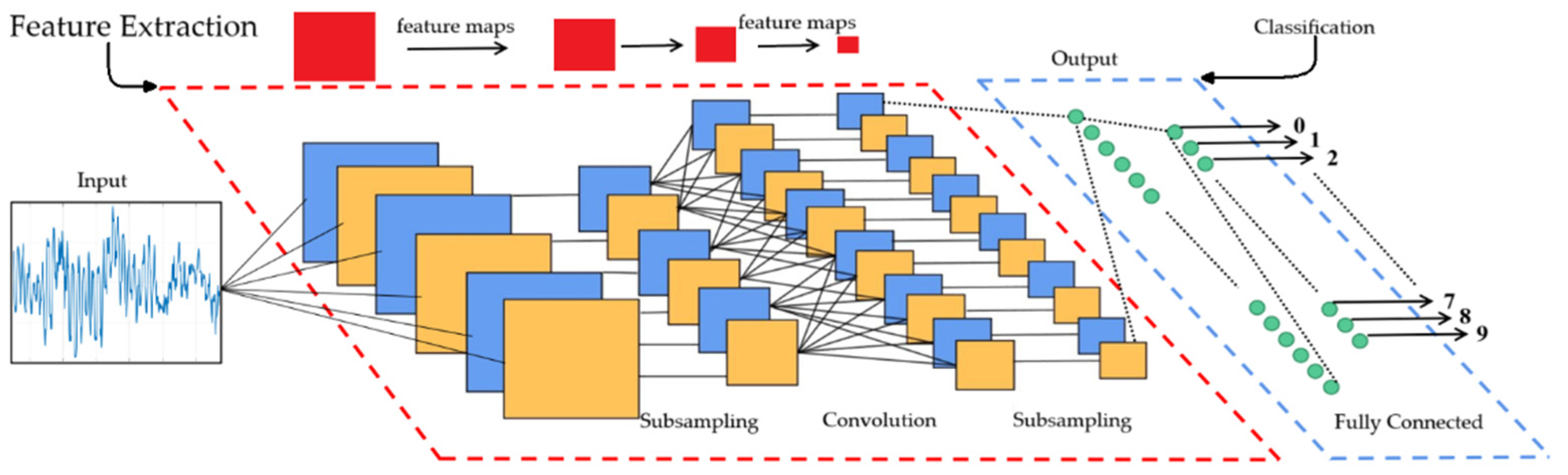
11.3. Automated NDT Systems and Machine Learning

The advancement of machine learning (ML) and deep learning (DL) gives an opportunity to apply them in the NDT field. Most NDT methods have the features of subjectiveness, difficult image processing, and repetitiveness, which provide an incentive for automation. While humans are subjective, prone to errors, and produce varying results, automated inspections are objective, precise, faster, and safer. There are certainly some core processes like data evaluation that cannot be replaced, but ML can still be a reliable tool to double-check the validity of the results. To fully automate the inspection process, the examination can be segmented into three components: data collection, data analysis, and identification of defects. The process of data collection could be accomplished through independent navigation carried out by drones or robots. The predetermined paths for automation can be established using planning techniques and algorithms, or by recognizing natural landmarks from outside the aircraft strategically positioned in the surrounding area to support the navigation system [234,235,236,237]. The utilization of drones eliminates the need for the physical presence of a human inspector near the object, enabling rapid and accurate data collection [238]. Data processing involves noise reduction and the extraction of significant features. The autoencoder, a deep-learning network, is commonly used to enhance the signal-to-noise ratio (SNR). Investigations have demonstrated its effectiveness in improving defect classification accuracy by 1 to 10% through denoising. Similarly, other techniques like empirical mode decomposition, principal component analysis, and singular value decomposition can also be employed for noise reduction, contributing to more accurate defect detection. A hierarchical AI-ADC method has shown that advanced denoising techniques can significantly improve defect classification, enhancing accuracy by as much as 32% in specific applications [239]. The anomaly detection approach serves the purpose of extracting meaningful information or reducing data. The determination of suitable values is made by the algorithm. A fully connected neural network and a convolutional neural network are employed as network structures for identifying defects. Numerous experiments have been conducted, demonstrating the ability to detect various flaws in metallic constructions. Nevertheless, utilizing deep learning on anisotropic materials like composites remains challenging due to their anisotropy and reflections within layers [240].
Currently, the use of deep-learning-driven automation in the field of non-destructive testing is comparatively low across various industries. The use of artificial intelligence is a subject of significant interest for research. The effective integration of deep learning, as well as other AI strategies, has the potential to greatly enhance the effectiveness of NDT, leading to enhanced precision and reduced time consumption. The endorsement of automated intelligent systems by industries and regulatory authorities will depend upon their prevalent acceptance. Further advancements are necessary in order to mechanize the NDT procedures.

11.4. Future of NDT of Structural Composites

The market for the non-destructive evaluation (NDE) of composites is experiencing a gradual increase, with a rising engagement across various application domains. The global market for testing composites is estimated to reach a value of USD 3.34 billion by 2027, with a detailed breakdown by region illustrated in Figure 33. The demand for NDE of structural composites is continuously rising, leading to a significant research emphasis on its advancement [241]. The emergence of innovative disruptive technologies has prompted a focus on enhancing the current methodologies as well. There exist numerous challenges associated with NDE techniques in the realm of composite materials, the most pressing of which revolves around the analysis and comprehension of the substantial volume of data generated during testing. A plausible remedy for these obstacles lies in the implementation of artificial intelligence and machine learning for pattern recognition and data analysis within NDE methodologies [242]. Alternatively, these methods are typically labor-intensive and necessitate highly proficient operators. These issues can be mitigated through the utilization of artificial algorithms or network coding to facilitate the automated inspection and detection of imperfections and anomalies, thereby diminishing the occurrence of human errors [243].
Research into the application of signal processing and statistical analysis techniques to address challenges in NDE has been a predominant area of interest for researchers and practitioners over the years, with a specific emphasis on interpreting NDE signals for flaw identification and characterization [245]. An illustration of this is the utilization of clustering, aimed at recognizing inherent groupings within acquired signals, which has demonstrated numerous practical uses in the analysis of acoustic emission signals [246]. The identification of clusters within signals can be employed to distinguish different categories of acoustic emission signals, which are subsequently associated with various defects, like fiber breakage, matrix cracking, and interface malfunction. Matrix decomposition and neural networks (NN) are among the various machine-learning approaches used in the field. The application of matrix decomposition in guided-wave PHM involves separating damage events and their changes over extended time periods of guided-wave measurements, typically ranging from 10 to 1000 to 100,000 s. This technique is particularly useful for extracting information in environments with noise and temperature variations [247]. On the other hand, NNs find application in NDE scenarios, specifically in the classification of ultrasonic signals for crack detection [248]. Additionally, neural networks can facilitate defect localization, the characterization of material properties, and damage assessment. The future trajectory of composites’ NDE involves a shift towards data-driven methodologies, which offer enhanced efficiency by leveraging advanced techniques, like deep learning, transfer learning, and physics-informed machine learning. This trend is evidenced by the increasing number of publications on this subject [249,250].
Upcoming advancements in NDT include research into new sensing techniques designed for composite materials. One notable area is the development of frequency-modulated continuous wave (FMCW) radar sensing, which is being applied to assess wind turbine blades [251]. Moreover, this technological innovation has demonstrated utility in addressing various material characterization obstacles, leveraging both static and dynamic loading conditions. For instance, it has proven effective in detecting surface and subsurface damages, serving as a distinguishing factor in the identification of porosity elements, as well as in distinguishing between the frozen and liquid phases of fluid (such as water) ingress [252,253]. By using this advanced sensing technique, it becomes feasible to proactively identify and mitigate the progressive deterioration of wind turbine blades, thereby enhancing the operational efficacy of the blades. The FMCW radar sensor offers the benefit of being a contactless and non-damaging approach that remains unaffected by environmental factors, like smoke, mist, and fog. The versatility of this sensing technology can enhance existing defect detection methods, including visual and thermal inspections, by integrating innovative digital analysis and digital twin systems with FMCW systems in the future [254].
The use of digital analysis through a data-driven approach represents a sophisticated and rapidly evolving technique within sensing technologies. These digital instruments are increasingly crucial for facilitating the seamless integration of information and data sourced from various monitoring systems, particularly due to the escalating intricacies and interdependencies prevalent in system networks, including NDT methodologies. Defined as a digital twin (DT), this concept involves a virtual representation of devices and a physical system in relation to their lifecycle and surrounding conditions, akin to a reflective image of a tangible entity that establishes a connection between physical and virtual entities. This approach, characterized by its immediacy and simplicity, has the potential to enhance the interaction between humans and objects while requiring minimal specialized knowledge from end users. It is anticipated that the DT framework will undergo further experimentation and analyses in diverse practical scenarios, such as robotic platforms, to demonstrate that operators can effectively engage with their physical assets, as seen in NDT technology, through online platforms and visualized virtual environments [255].
The deployment of cutting-edge technologies presents significant opportunities for NDT methods. For instance, techniques employing terahertz technology have already demonstrated advantages in terms of depth of penetration. Additionally, the potential of techniques like free electron lasers and contemporary spallation sources has been evident. Moreover, the latest synchrotron X-ray and neutron facilities bring new and enhanced capabilities [110,242,256].
The development of self-healing materials and their feasibility allowed for an increasing interest in its industrial application. These technologies are inspired by the regenerative capabilities of living organisms and can involve the incorporation of either embedded modifications or surface coatings into materials. The primary objective of self-healing materials is to autonomously repair damage, thereby minimizing the need for manual interventions and associated downtime [257]. Self-healing composite materials represent a major advancement in structural engineering, particularly for aerospace applications. These materials have the ability to autonomously repair micro-cracks and minor damage, thereby enhancing structural integrity and extending the lifespan of critical components [258]. This inherent self-healing capability translates into substantial benefits, including a potential reduction in the frequency and associated costs of manual repairs [259].
The future significance of self-healing composites is promising in aerospace applications, where undetected damage can have catastrophic consequences. Traditional materials require meticulous inspection routines to identify and address such damage before it compromises structural integrity. Self-healing in composites, however, offers an autonomous solution, potentially mitigating the risk of unforeseen failures. Furthermore, from the perspective of NDT, self-healing composites introduce a unique advantage. The incorporation of self-healing mechanisms can alter the material’s response to certain NDT techniques due to the release of the healing agent [260]. This altered response can be used to enhance the sensitivity and precision of NDT inspections, potentially allowing for the detection of even smaller types of damage or reducing the number of different NDT methods required for a comprehensive assessment [261]. Figure 34 shows the application of passive infrared thermography to monitor the microcapsule’s healing process. The temperature field was significantly altered by thermal release caused by the broken resin filling the cracks. These studies demonstrate the efficiency of the self-healing process and NDT for composite materials to detect and repair damage [262].
AI integration is becoming ubiquitous, with applications emerging across diverse fields from healthcare to manufacturing. The integration of artificial intelligence with NDT methods is an example of this powerful approach, allowing for the enhancement of damage detection in composite materials. In this sense, machine learning and deep learning hold a significant potential for increasing NDT accuracy and employability for composite materials. Improvements in efficiency and reliability are also expected and achievable using AI [262].
One of the key benefits of AI in NDT is its ability to improve detection accuracy and sensitivity. AI algorithms excel at analyzing complex data patterns acquired from NDT sensors. This enables them to identify subtle anomalies that might escape human inspectors, leading to more comprehensive damage characterization [263,264]. Additionally, AI automates the process of defect detection and classification, minimizing the errors associated with manual interpretation, a common challenge in traditional NDT [265].
The use of algorithms and signal processing techniques has the potential to enhance the detection of damage and defects, significantly increasing the performance of NDT methods beyond their standard capabilities and leading to cost-saving processes [266,267]. This potential was further explored through the application of algorithms to interpret data from two different NDT techniques. By integrating the IRT and DIC results for damage detection on composite materials, the algorithm enabled the identification of subtle defects that qualitatively may have posed a challenge. A study characterized defects in a CFRP sample using IRT pulse-phase and lock-in thermography, enabled by an algorithm that improved precision and defect localization. This algorithm, combined with the two IRT techniques, performed Fourier transforms, extracted phase information, and enhanced thermal images, thereby making defect detection more accurate and reliable [268]. As shown in Figure 35 the algorithm translated thermal data into meaningful metrics that could be quantitatively compared across the different techniques used.
A study evaluated the use of sparse convolutional neural networks (SCNN) to classify acoustic emission features during an additive manufacturing process [269]. The results indicate that SCNN was able to classify the signals by monitoring the selective laser melting (SLM) process with deposition porosity and quality, as shown in Figure 36.
Furthermore, AI facilitates faster analysis of NDT data compared to conventional methods. AI algorithms can process vast amounts of data in a fraction of the time, leading to rapid completion time for an inspection and, thus, enhancing productivity [270]. Early damage detection is another crucial advantage offered by AI in NDT. By enabling the identification of damage in real time and in the early stages, AI empowers proactive maintenance strategies, enhancing capabilities of avoiding catastrophic failures and ensuring the safety of composite structures [271,272].

12. Conclusions

Ensuring the integrity and reliability of composite materials is crucial for the aerospace industry’s ongoing pursuit of enhanced safety, efficiency, and performance. This review highlights the critical role that non-destructive testing techniques play in maintaining the structural health of these materials. The paper offers practical guidance for selecting NDT methods, presenting easy-to-understand approaches for choosing the appropriate technique based on the specific type of composite material being evaluated. Additionally, it showcases applications of NDT for detecting and characterizing damage and defects within these materials, providing valuable insights for aerospace engineers and inspection professionals.
NDT technology advancements are also presented here. It is shown how its relevance is tied to the rapid development and implementation of complex new materials, such as PMCs, MMCs, and CMCs. Innovative NDT methods are not only needed to detect and evaluate existing defects, but also to monitor the health of components in real-time, as well as predict the onset of potential failures, and guide maintenance decisions before catastrophic failures occur. Furthermore, integrating artificial intelligence and machine learning with NDT has the potential to revolutionize how assessments are conducted, leading to smarter, faster, and more accurate diagnostics. This integration promises to enhance the predictive capabilities of NDT, ultimately contributing to the longevity and reliability of aerospace components.
In conclusion, as the aerospace industry continues to evolve towards more advanced composite designs, the development of equally advanced NDT techniques is needed. Focus on research and innovation in the NDT will ensure that the aerospace sector can continue to rely on these materials for future applications, safeguarding both technological progress and human lives.

Author Contributions

T.L.L.O. was responsible for supervising and writing the original draft. M.H. and S.M. assisted in writing the original draft. R.B.S. focused on writing—review and editing of the manuscript. All authors have read and agreed to the published version of the manuscript.

Funding

This research received no external funding.

Institutional Review Board Statement

Not applicable.

Informed Consent Statement

Thiago Luiz Lara Oliveira, Maha Hadded, Saliha Mimouni, and Renata Brandelli Schaan wrote the paper. All authors have read and agreed to the published version of the manuscript.

Data Availability Statement

Not applicable.

Acknowledgments

The authors wish to express their sincere gratitude to Emilien BOURDON and Alan JEAN-MARIE for their support and comprehension regarding the significance of publishing this review article. Their encouragement was vital for the successful accomplishment of this publication.

Conflicts of Interest

The authors declare that there are no conflicts of interest regarding the publication of this paper.

References

  1. Zhang, X.; Chen, Y.; Hu, J. Recent advances in the development of aerospace materials. Prog. Aerosp. Sci. 2018, 97, 22–34. [Google Scholar] [CrossRef]
  2. Challenger, K.D. The damage tolerance of carbon fiber reinforced composites—A workshop summary. Compos. Struct. 1986, 6, 295–318. [Google Scholar] [CrossRef]
  3. Nayak, V.K. Composite Materials in Aerospace Applications. Int. J. Sci. Res. Publ. 2014, 4, 1–10. [Google Scholar]
  4. Shrivastava, S.; Rajak, D.K.; Joshi, T.; Singh, D.K.; Mondal, D.P. Ceramic Matrix Composites: Classifications, Manufacturing, Properties, and Applications. Ceramics 2024, 7, 652–679. [Google Scholar] [CrossRef]
  5. Karadimas, G.; Salonitis, K. Ceramic Matrix Composites for Aero Engine Applications—A Review. Appl. Sci. 2023, 13, 3017. [Google Scholar] [CrossRef]
  6. Boeing. 787 Dreamliner By Design. Available online: https://www.boeing.com/commercial/787/by-design (accessed on 10 August 2024).
  7. Vlasova, V. Using composite materials in aircraft. AIP Conf. Proc. 2019, 2171, 030020. [Google Scholar] [CrossRef]
  8. Kesarwani, S. Polymer Composites in Aviation Sector. Int. J. Eng. Res. Technol. 2017, 6, 518–525. [Google Scholar] [CrossRef]
  9. Rajak, D.K.; Wagh, P.H.; Linul, E. Manufacturing Technologies of Carbon/Glass Fiber-Reinforced Polymer Composites and Their Properties: A Review. Polymers 2021, 13, 3721. [Google Scholar] [CrossRef]
  10. Mangalgiri, P.D. Composite materials for aerospace applications. Bull. Mater. Sci. 1999, 22, 657–664. [Google Scholar] [CrossRef]
  11. Léonard, P.L.Y.; Nylander, J.W. Sustainability Assessment of Composites in Aero-Engine Components. In Proceedings of the Design Society: DESIGN Conference; Cambridge University Press: Cambridge, UK, 2020; pp. 1989–1998. [Google Scholar] [CrossRef]
  12. Evans, E.E.; Brooks, R.A.; Liu, J.; Hall, E.C.; Liu, H.; Lowe, T.J.E.; Withers, P.J.; Kinloch, A.J.; Dear, J.P. Comparison of X-ray Computed Tomography and Ultrasonic C-Scan Techniques and Numerical Modelling of Impact Damage in a CFRP Composite Laminate. Appl. Compos. Mater. 2023, 31, 249–264. [Google Scholar] [CrossRef]
  13. Bechmann, J.; Hidalgo, C.; Bricout, S. Environmental analysis of innovative sustainable composites with potential use in aviation sector—A life cycle assessment review. Sci. China Technol. Sci. 2017, 60, 1301–1317. [Google Scholar] [CrossRef]
  14. Marsh, G. Aero engines lose weight thanks to composites. Reinf. Plast. 2012, 5, 32–35. [Google Scholar] [CrossRef]
  15. Zimmermann, N.; Wang, P.H. A review of failure modes and fracture analysis of aircraft composite materials. Eng. Fail. Anal. 2020, 115, 104692. [Google Scholar] [CrossRef]
  16. Lakhdar, Y.; Tuck, C.; Binner, J.; Terry, A.; Goodridge, R. Additive manufacturing of advanced ceramic materials. Prog. Mater. Sci. 2021, 16, 100736. [Google Scholar] [CrossRef]
  17. Senthil, S.; Raguraman, M.; Manalan, D.T. Manufacturing processes & recent applications of aluminium metal matrix composite materials: A review. Mater. Today Proc. 2021, 45, 5934–5938. [Google Scholar] [CrossRef]
  18. Tatiparthi, A. Investigation of Microcrack Growth in [0/90]s Graphite Epoxy Composite Laminates Using X-Ray Microtomography. Master’s Thesis, University of New Orleans, New Orleans, LA, USA, 2004. [Google Scholar]
  19. Norris, C.J.; Bond, P.; Trask, R.S. The role of embedded bioinspired vasculature on damage formation in self-healing carbon fibre reinforced composites. Compos. Part A Appl. Sci. Manuf. 2011, 42, 639–648. [Google Scholar] [CrossRef]
  20. Post, W.; Kersemans, M.; Solodov, I.; Van Den Abeele, K.; García, S.J.; Van Der Zwaag, S. Non-destructive monitoring of delamination healing of a CFRP composite with a thermoplastic ionomer interlayer. Compos. Part A Appl. Sci. Manuf. 2017, 101, 243–253. [Google Scholar] [CrossRef]
  21. Katunin, A.; Dragan, K.; Dziendzikowski, M. Damage identification in aircraft composite structures: A case study using various non-destructive testing techniques. Compos. Struct. 2015, 127, 1–9. [Google Scholar] [CrossRef]
  22. D’Accardi, E.; Palano, F.; Tamborrino, R.; Palumbo, D.; Taty, A.; Terzi, R.; Galietti, U. Pulsed Phase Thermography Approach for the Characterization of Delaminations in CFRP and Comparison to Phased Array Ultrasonic Testing. J. Nondestruct. Eval. 2019, 38, 20. [Google Scholar] [CrossRef]
  23. Chaki, S.; Krawczak, P. Non-Destructive Health Monitoring of Structural Polymer Composites: Trends and Perspectives in the Digital Era. Materials 2022, 15, 7838. [Google Scholar] [CrossRef]
  24. da Silva, R.R.; de Padua, G.X. Nondestructive Inspection Reliability: State of the Art. In Nondestructive Testing Methods and New Applications; InTech: Rijeka, Croatia, 2012. [Google Scholar] [CrossRef]
  25. Jolly, M.R.; Prabhakar, A.; Sturzu, B.; Hollstein, K.; Singh, R.; Thomas, S.; Foote, P.; Shaw, A. Review of Non-destructive Testing (NDT) Techniques and their applicability to thick walled composites. Procedia CIRP 2015, 38, 129–136. [Google Scholar] [CrossRef]
  26. Sreenivasulu, D.; Dasari, C. Fundamental ideas of nanomaterials and nanotechnology. In Proceedings of National Seminar; Roshan Publications: Siliguri, India, 2017; pp. 90–93. [Google Scholar]
  27. Naik, R.A. Simplified Micromechanical Equations for Thermal Residual Stress Analysis of Coated Fiber Composites. Compos. Technol. Res. 1992, 14, 182–186. [Google Scholar] [CrossRef]
  28. Chawla, K.K. Reinforcements. In Composite Materials: Science and Engineering, 4th ed.; Springer: Cham, Switzerland, 2019; pp. 7–74. [Google Scholar] [CrossRef]
  29. MatWeb. E-Glass Fiber, Generic. 1998. Available online: https://www.matweb.com/search/datasheet.aspx?MatGUID=d9c18047c49147a2a7c0b0bb1743e812 (accessed on 13 June 2024).
  30. McBeck, J.; Ben-Zion, Y.; Renard, F. Fracture network localization preceding catastrophic failure in triaxial compression experiments on rocks. Front. Earth Sci. 2021, 9, 778811. [Google Scholar] [CrossRef]
  31. Jollivet, T.; Peyrac, C.; Lefebvre, F. Composite Material Damage Processes. Procedia Eng. 2013, 66, 746–758. [Google Scholar] [CrossRef]
  32. Parveez, B.; Kittur, M.I.; Badruddin, I.A.; Kamangar, S.; Hussien, M.; Umarfarooq, M.A. Scientific Advancements in Composite Materials for Aircraft Applications: A Review. Polymers 2022, 14, 5007. [Google Scholar] [CrossRef]
  33. Lakshminarayan, U.; Marcus, H.L. An Experimental Study of the Relationship Between Microstructure and Mechanical Properties of a Ceramic Composite Fabricated by Selective Laser Sintering; Technical Report; University of Texas: Austin, TX, USA, 1992. [Google Scholar]
  34. Glass, D.E. Ceramic Matrix Composite (CMC) Thermal Protection Systems (TPS) and Hot Structures for Hypersonic Vehicles. In Proceedings of the 15th AIAA Space Planes and Hypersonic Systems and Technologies Conference, Dayton, OH, USA, 28 April–1 May 2008. [Google Scholar]
  35. Klocke, F.; Klink, A.; Veselovac, D.; Aspinwall, D.K.; Soo, S.L.; Schmidt, M.; Schilp, J.; Levy, G.; Kruth, J.-P. Turbomachinery component manufacture by application of electrochemical, electro-physical and photonic processes. CIRP Ann. 2014, 63, 703–726. [Google Scholar] [CrossRef]
  36. Jadhav, S.; Sankpal, J.; Chaudhari, M.; Patil, N. A Review on Drilling of Metal Matrix Composites. Int. J. Curr. Eng. Technol. 2016, 6, 82–88. [Google Scholar]
  37. Bahl, S. Fiber reinforced metal matrix composites—A review. Mater. Today Proc. 2021, 39, 317–323. [Google Scholar] [CrossRef]
  38. Jarzabek, D.M.; Chmielewski, M.; Dulnik, J.; Strojny-Nedza, A. The Influence of the Particle Size on the Adhesion Between Ceramic Particles and Metal Matrix in MMC Composites. J. Mater. Eng. Perform. 2016, 25, 3139–3145. [Google Scholar] [CrossRef]
  39. Rawal, S.P. Metal-matrix composites for space applications. J. Miner. Met. Mater. Soc. 2001, 53, 14–17. [Google Scholar] [CrossRef]
  40. Huda, D.; El Baradie, M.A.; Hashmi, M.S.J. Metal-Matrix Composites: Materials Aspects. Part II. J. Mater. Process. Technol. 1993, 37, 529–541. [Google Scholar] [CrossRef]
  41. Mukherjee, G.S.; Jain, A.; Banerjee, M. Engineering Matrix Materials for Composites: Their Variety, Scope, and Applications. Fine Chem. Eng. 2023, 4, 13–17. [Google Scholar] [CrossRef]
  42. Chajkrapani, P.; Suryakumari, T.S.A. Mechanical properties of aluminium metal matrix composites-A review. Mater. Today Proc. 2021, 45, 5960–5964. [Google Scholar] [CrossRef]
  43. Vairamuthu, J.; Velmurugan, P.; Manohar, N.J.; Kannan, C.R.; Manivannan, S.; Stalin, B. Wear experimentation and parametric optimization on synthesized copper titanium composite. IOP Conf. Ser. Mater. Sci. Eng. 2020, 988, 102106. [Google Scholar] [CrossRef]
  44. Chandrasekhar, B.; Dharme, A.; Sharma, S.K.; Taluja, R.; Jarali, O.A.; Kalra, R.; Kumar, G. Role of CNT in influencing the mechanical properties of the Mg-based composites: An overview. Mater. Today Proc. 2023, in press. [Google Scholar] [CrossRef]
  45. Aluminum 7075-T6; 7075-T651. Available online: https://www.matweb.com/search/datasheet.aspx?MatGUID=4f19a42be94546b686bbf43f79c51b7d (accessed on 13 June 2024).
  46. Magnesium WE43-T6, Cast. Available online: https://www.matweb.com/search/DataSheet.aspx?MatGUID=4b8a8c13cf354fc5893a40cf8eca022c (accessed on 13 June 2024).
  47. Titanium Ti-6Al-4V (Grade 5), STA. Available online: https://www.matweb.com/search/DataSheet.aspx?MatGUID=b350a789eda946c6b86a3e4d3c577b39 (accessed on 13 June 2024).
  48. Silicon Carbide SiC. Available online: https://www.makeitfrom.com/material-properties/Silicon-Carbide-SiC (accessed on 13 June 2024).
  49. Alumina (Aluminum Oxide, Al2O3). Available online: https://www.makeitfrom.com/material-properties/Alumina-Aluminum-Oxide-Al2O3 (accessed on 13 June 2024).
  50. Yu, M.-F.; Lourie, O.; Dyer, M.J.; Moloni, K.; Kelly, T.F.; Ruoff, R.S. Strength and Breaking Mechanism of Multiwalled Carbon Nanotubes Under Tensile Load. Science 2000, 287, 637–640. [Google Scholar] [CrossRef]
  51. Boron Carbide B4C. Available online: https://www.makeitfrom.com/material-properties/Boron-Carbide-B4C (accessed on 13 June 2024).
  52. Dauksys, R.J.; Ray, J.D. Properties of Graphite Fiber Nonmetallic Matrix Composites. J. Compos. Mater. 1969, 3, 684–698. [Google Scholar] [CrossRef]
  53. Ozturk, F.; Cobanoglu, M.; Ece, R.E. Recent advancements in thermoplastic composite materials in the aerospace industry. J. Thermoplast. Compos. Mater. 2023, 37, 3084–3116. [Google Scholar] [CrossRef]
  54. Huntsman. Technical Sheet Araldite®LY5052/Aradur®5052. 2012. Available online: https://www.huntsman.com/docs/Documents/ARALDITE%20LY%205052%20ARADUR%205052%20Technical%20Datasheet%20%28US%29.pdf (accessed on 13 June 2024).
  55. Granado, L.; Tavernier, R.; Henry, S.; Oye, R.A.; Foyer, G.; David, G.; Caillol, S. Toward Sustainable Phenolic Thermosets with High Thermal Performances. ACS Sustain. Chem. Eng. 2019, 7, 7209–7217. [Google Scholar] [CrossRef]
  56. VICTREX. PEEK POLYMER 151G. 2024. Available online: https://www.victrex.com/en/downloads/datasheets/victrex-peek-151g (accessed on 13 June 2024).
  57. Arkema. Kepstan Technical Data—7000 Series. 2012. Available online: https://www.aplast.fr/wp-content/uploads/2016/02/KEPSTAN-7000.pdf (accessed on 13 June 2024).
  58. Hsissou, R.; Seghiri, R.; Benzekri, Z.; Hilali, M.; Rafik, M.; Elharfi, A. Polymer composite materials: A comprehensive review. Compos. Struct. 2021, 262, 113640. [Google Scholar] [CrossRef]
  59. Ramesh, M.; Rajeshkumar, L.N.; Srinivasan, N.; Kumar, D.V.; Balaji, D. Influence of filler material on properties of fiber-reinforced polymer composites: A review. e-Polymers 2022, 22, 898–916. [Google Scholar] [CrossRef]
  60. Diógenes, O.B.; de Oliveira, D.R.; da Silva, L.R.; Pereira, G.; Mazzetto, S.E.; Araujo, W.S.; Lomonaco, D. Development of coal tar-free coatings: Acetylated lignin as a bio-additive for anticorrosive and UV-blocking epoxy resins. Prog. Org. Coat. 2021, 161, 106533. [Google Scholar] [CrossRef]
  61. He, T.; Chen, N.; Fang, J.; Cai, G.; Wang, J.; Chen, B.; Liang, Q. Micro/nano carbon spheres as liquid lubricant additive: Achievements and prospects. J. Mater. Sci. Technol. 2021, 85, 23–36. [Google Scholar] [CrossRef]
  62. Mirdehghan, S.A. Fibrous polymeric composites. In Engineered Polymeric Fibrous Materials; The Textile Institute Book Series; Latifi, M., Ed.; Woodhead Publishing: Cambridge, UK, 2021; pp. 1–58. [Google Scholar] [CrossRef]
  63. MatWeb. S-Glass Fiber, Generic. 1998. Available online: https://www.matweb.com/search/DataSheet.aspx?MatGUID=6eb41a1324834878a1524129d915ca09 (accessed on 13 June 2024).
  64. Seydibeyoğlu, M.Ö.; Dogru, A.; Wang, J.; Rencheck, M.; Han, Y.; Wang, L.; Seydibeyoğlu, E.A.; Zhao, X.; Ong, K.; Shatkin, J.A.; et al. Review on Hybrid Reinforced Polymer Matrix Composites with Nanocellulose, Nanomaterials, and Other Fibers. Polymers 2023, 15, 984. [Google Scholar] [CrossRef]
  65. Khoramishad, H.; Mousavi, M.V. Hybrid Polymer Composite Materials. In Proceedings of the 7th International Conference on Applied Science and Technology, Karbala, Iraq, 27–28 March 2019. [Google Scholar] [CrossRef]
  66. Annamalai, I.; Karthik, K.; Kumar, N.; Muthuselvan, S.; Vignesh, M.; Dhanush, Y.J. Experimental Investigation of Mechanical Properties of GLARE Composite with Different Layup Sequences. Mater. Today Proc. 2021, 46, 1371–1375. [Google Scholar] [CrossRef]
  67. Huang, T.; Bobyr, M. A Review of Delamination Damage of Composite Materials. J. Compos. Sci. 2023, 7, 468. [Google Scholar] [CrossRef]
  68. Ghaidan, K.A.A. Prediction of Delamination in Glass Fibre Reinforced Composite Materials Using Elasto-Plastic Modelling. Ph.D. Thesis, University of Southern Queensland, Toowoomba, Australia, 2019. [Google Scholar]
  69. Juhász, Z.; Szekrényes, A. The effect of delamination on the critical buckling force of composite plates: Experiment and simulation. Compos. Struct. 2017, 168, 456–464. [Google Scholar] [CrossRef]
  70. Ismail, S.O.; Dhakal, H.N.; Popov, I.; Beaugrand, J. Comprehensive study on machinability of sustainable and conventional fibre reinforced polymer composites. Eng. Sci. Technol. Int. J. 2016, 19, 2043–2052. [Google Scholar] [CrossRef]
  71. Boon, Y.D.; Joshi, S.C. A review of methods for improving interlaminar interfaces and fracture toughness of laminated composites. Mater. Today Commun. 2019. [Google Scholar] [CrossRef]
  72. Cozza, R.C.; Verma, V. Evaluation of fracture toughness of epoxy polumer composite incorporating micro/nano silica, rubber and CNTs. Polímeros Ciência E Tecnol. 2020, 30, e2020030. [Google Scholar] [CrossRef]
  73. Henaff-Gardin, C.; Lafarie-Frenot, M.C. Specificity of Matrix Cracking Development in CFRP Laminates Under Mechanical or Thermal Loadings. Int. J. Fatigue 2002, 24, 171–177. [Google Scholar] [CrossRef]
  74. Tee, Z.T.; Yeap, S.P.; Hassan, C.S.; Kiew, P.L. Nano and non-nano fillers in enhancing mechanical properties of epoxy resins: A brief review. Polym. Plast. Technol. Mater. 2021, 61, 709–725. [Google Scholar] [CrossRef]
  75. Mastalia, M.; Abdollahnejad, Z.; Pacheco-Torgal, F. Performance of waste based alkaline mortars submitted to accelerated. Resour. Convservation Recycl. 2018, 129, 12–19. [Google Scholar] [CrossRef]
  76. Alves, L.C.d.S.; Ferreira, R.A.d.R.; Machado, L.B.; Motta, L.A.d.C. Optimization of metakaolin-based geopolymer reinforced with sisal fibers using response surface methology. Ind. Crops Prod. 2019, 139, 111551. [Google Scholar] [CrossRef]
  77. Dolbachian, L.; Harizi, W.; Aboura, Z. Experimental Lineair and Nonlinear Vibration Methods for the Structural Health Moniktoring (SHM) of Polymer-Matrix Composites (PMCs). Vibration 2024, 7, 281–325. [Google Scholar] [CrossRef]
  78. Daniel, I.M.; Ishai, O. Strenght of Unidirectional Lamina—Micromechanics. In Engineering Mechanics of Composite Materials, 2nd ed.; Oxford University Press: New York, NY, USA, 2006; pp. 98–119. [Google Scholar]
  79. Tanasehte, M.; Hader, A.; Achik, I.; Sbiaai, H.; Boughaleb, Y. The Matrix–Fiber Interaction Effect on the Avalanche Breaking in the Failure Process of Composite Materials. Phys. A Stat. Mech. Its Appl. 2020, 553, 124223. [Google Scholar] [CrossRef]
  80. NagarajaGanesh, B.; Rekha, B. Morphology and damage mechanism of lignocellulosic fruit fibers reinforced polymer composites: A comparative study. Discov. Appl. Sci. 2019, 1, 1250. [Google Scholar] [CrossRef]
  81. Vieille, B.; Gonzalez, J.D.; Bouvet, C. Fracture mechanics of hybrid composites with ductile matrix and brittle fibers: Influence of temperature and constraint effect. J. Compost. Mater. 2019, 53, 1361–1376. [Google Scholar] [CrossRef]
  82. Wu, Y.; Ju, J. Elastoplastic damage micromechanics for continuous fiber-reinforced ductile matrix composites with progressive fiber breakage. Int. J. Damage Mech. 2017, 26, 4–28. [Google Scholar] [CrossRef]
  83. Leung, C.K.Y.; Li, V.C. Effect of Fiber Inclination on Crack Bridging Stress in Brittle Fiber Reinforced Brittle Matrix Composites. J. Mech. Phys. Solids 1992, 40, 1333–1362. [Google Scholar] [CrossRef]
  84. Phoenix, S.L.; Beyerlein, I.J. Statistical Strength Theory for Fibrous Composite Materials. In Comprehensive Composite Materials; Chou, T.W., Ed.; Elsevier: Amsterdam, The Netherlands, 2000; Volume 1, pp. 559–639. [Google Scholar] [CrossRef]
  85. Farda, M.Y.; Brian, R.; Pankretz, H. Correlation of nanoscale interface debonding and multimode fracture in polymer carbon composites with long-term hygrothermal effects. Mech. Mater. 2020, 150, 103601. [Google Scholar] [CrossRef]
  86. Mahmoud Zaghloul, M.Y.; Yousry Zaghloul, M.M.; Yousry Zaghloul, M.M. Physical analysis and statistical investigation of tensile and fatigue behaviors of glass fiber-reinforced polyester via novel fibers arrangement. Compos. Mater. 2023, 57, 147–166. [Google Scholar] [CrossRef]
  87. Liu, F.; Danyong, W.; Liu, J.; Wei, H.; Zhang, H.; Xu, J.; Li, S.; Qin, Z.; Wang, R.; Jia, H.; et al. Reviews on Interfacial Properties of the Carbon Fiber Reinforced Polymer Composites. J. Phys. Conf. Ser. 2020, 1637, 012027. [Google Scholar] [CrossRef]
  88. Wu, Q.; Zhao, R.; Zhu, J.; Wang, F. Interfacial improvement of carbon fiber reinforced epoxy composites by tuning the content of curing agent in sizing agent. Appl. Surf. Sci. 2020, 504, 144384. [Google Scholar] [CrossRef]
  89. Ojha, S.; Bisaria, H.; Mohanty, S.; Kanny, K. Fractographic Analysis of Fiber-Reinforced Polymer Laminate Composites for Marine Applications: A Comprehensive Review. Polym. Compos. 2024, 45, 6771–6787. [Google Scholar] [CrossRef]
  90. Rahman, K.M.; Vorontsov, V.A.; Flitcroft, S.M.; Dye, D. A High Strength Ti–SiC Metal Matrix Composite. Adv. Eng. Mater. 2017, 19, 17000027. [Google Scholar] [CrossRef]
  91. Clyne, T.W.; Withers, P.J. The interfacial region. In An Introduction to Metal Matrix Composites; Cambridge University Press: Cambridge, UK, 1993; Volume 134, pp. 166–217. [Google Scholar]
  92. Requena, G.; Garcés, G.; Fernández, R.; Schöbel, M. Determination of Internal Stresses in Lightweight Metal Matrix Composites. In Neutron Diffraction; Khidirov, I., Ed.; InTech: Rijeka, Croatia, 2012; pp. 257–286. [Google Scholar] [CrossRef]
  93. Abazari, S.; Shamsipur, A.; Bakhsheshi-Rad, H.R.; Ismail, A.F.; Sharif, S.; Razzaghi, M.; Ramakrishna, S.; Berto, F. Carbon Nanotubes (CNTs)-Reinforced Magnesium-Based Matrix Composites: A Comprehensive Review. Materials 2020, 13, 4421. [Google Scholar] [CrossRef]
  94. Meignanamoorthy, M.; Ravichandran, M.; Mohanavel, V.; Afzal, A.; Sathish, T.; Alamri, S.; Khan, S.A.; Saleel, C.A. Microstructure, Mechanical Properties, and Corrosion Behavior of Boron Carbide Reinforced Aluminum Alloy (Al-Fe-Si-Zn-Cu) Matrix Composites Produced via Powder Metallurgy Route. Materials 2021, 14, 4315. [Google Scholar] [CrossRef]
  95. Riquelme, A.; Rodrigo, P.; Escalera-Rodriguez, M.D.; Rams, J. Evaluation of the Wear Resistance and Corrosion Behavior of Laser Cladding Al/SiC Metal Matrix Composite Coatings on ZE41 Magnesium Alloy. Coatings 2021, 11, 639. [Google Scholar] [CrossRef]
  96. Hu, Q.; Zhou, X.; Tu, Y.; Lu, X.; Huang, J.; Jiang, J.; Deng, L.; Dong, S.; Cao, X. High-temperature mechanical properties and oxidation resistance of SiCf/SiC ceramic matrix composites with multi-layer environmental barrier coatings for turbine applications. Ceram. Int. 2021, 47, 30012–30019. [Google Scholar] [CrossRef]
  97. Karadimas, G.; Salonitis, K.; Georgarakis, K. Oxide Ceramic Matrix Composites for Aero Engine Applications—A Literature Review. Adv. Transdiciplinary Eng. 2021, 15, 153–158. [Google Scholar] [CrossRef]
  98. Bach, C.; Wehner, F.; Sieder-Katzmann, J. Investigations on an All-Oxide Ceramic Composites Based on Al2O3 Fibres and Alumina–Zirconia Matrix for Application in Liquid Rocket Engines. Aerospace 2022, 9, 684. [Google Scholar] [CrossRef]
  99. Fang, G.; Gao, X.; Song, Y. A Review on Ceramic Matrix Composites and Environmental Barrier Coatings for Aero-Engine: Material Development and Failure Analysis. Coatings 2023, 13, 357. [Google Scholar] [CrossRef]
  100. Chen, P.; Xiao, P.; Li, Z.; Liu, Z.; Pu, D.; Li, Y. Microstructure and Oxidation Behavior of a Novel Bilayer (c-AlPO4–SiCw–mullite)/SiC Coating for Carbon Fiber Reinforced CMCs. J. Eur. Ceram. Soc. 2019, 39, 3988–3999. [Google Scholar] [CrossRef]
  101. Quiney, Z.; Jeffs, S.P.; Gale, L.; Pattison, S.; Bache, M.R. Matrix cracking onset stress and strain as a function of temperature, and characterization of damage modes in SiCf/SiC ceramic matrix composites via acoustic emission. J. Eur. Ceram. Soc. 2023, 43, 2958–2967. [Google Scholar] [CrossRef]
  102. Ruys, A.J. Chapter: Introduction and Applications of SiC Ceramics. In Silicon Carbide Ceramics: Structure, Properties and Manufacturing; Elsevier eBooks; Elsevier: Amsterdam, The Netherlands, 2023; pp. 1–79. [Google Scholar]
  103. Yin, X.W.; Cheng, L.F.; Zhang, L.T.; Travitzky, N.; Greil, P. Fibre-reinforced multifunctional SiC matrix composite materials. Int. J. Rev. 2017, 62, 117–172. [Google Scholar] [CrossRef]
  104. Chengxin, Z.; Feng, C.; Yang, X.; Zhihang, P. Effects of sintering temperature on mechanical properties of alumina fiber reinforced alumina matrix composites. J. Sol-Gel Sci. Technol. 2019, 93, 185–192. [Google Scholar] [CrossRef]
  105. Sun, J.; Zhao, J.; Chen, Y.; Wang, L.; Yun, X.; Huang, Z. Macro-micro-nano multistage toughening in nano-laminated graphene ceramic composites. Mater. Today Phys. 2022, 22, 100595. [Google Scholar] [CrossRef]
  106. Khafagy, K.H.; Datta, S.; Chattopadhyay, A. Multiscale characterization and representation of variability in ceramic matrix composites. J. Compos. Mater. 2021, 55, 2431–2441. [Google Scholar] [CrossRef]
  107. Wang, L.-Y.; Luo, R.-Y.; Cui, G.; Chen, Z.-F. Oxidation Resistance of SiCf/SiC Composites with a PyC/SiC Multilayer Interface at 500 °C to 1100 °C. Corros. Sci. 2020, 167, 108522. [Google Scholar] [CrossRef]
  108. Xu, F.; Yao, T.; Xu, P.; Schulthess, J.L.; Matos, M.D.; Gonderman, S.; Gazza, J.; Kane, J.J.; Cordes, N.L. Multi-Scale Characterization of Porosity and Cracks in Silicon Carbide Cladding after Transient Reactor Test Facility Irradiation. Energies 2024, 17, 197. [Google Scholar] [CrossRef]
  109. Soutis, C. Fibre reinforced composites in aircraft construction. Prog. Aerosp. Sci. 2005, 41, 143–151. [Google Scholar] [CrossRef]
  110. Towsyfyan, H.; Biguri, A.; Boardman, R.; Blumensath, T. Successes and challenges in non-destructive testing of aircraft composite structures. Chin. J. Aeronaut. 2020, 33, 771–791. [Google Scholar] [CrossRef]
  111. Ewert, U.; Redmer, B.; Rädel, C.; Schnars, U.; Henrich, R.; Bavendiek, K.; Jahn, M. Mobile computed tomography for inspection of large stationary components in nuclear and aerospace. Mater. Trans. 2012, 53, 308–310. [Google Scholar] [CrossRef]
  112. Cramer, K.E. Current and future needs and research for composite materials NDE. In Proceedings of the Behavior and Mechanics of Multifunctional Materials and Composites XII, Denver, CO, USA, 4–8 March 2018; p. 500. [Google Scholar]
  113. Hyonny, K. Impact damage formation on composite aircraft structures. In JAMS 2015 Technical Review; Federal Aviation Administration: Washington, DC, USA, 2012; pp. 1–58. [Google Scholar]
  114. Robert Angus, S. Composite defects and their detection. Mater. Sci. Eng. 2009, 3, 103–143. [Google Scholar]
  115. Gros, X.E. An eddy current approach to the detection of damage caused by low-energy impacts on carbon fibre reinforced materials. Mater. Des. 1995, 16, 167–173. [Google Scholar] [CrossRef]
  116. Soutis, C. Carbon fiber reinforced plastics in aircraft construction. Mater. Sci. Eng. 2005, 412, 171–176. [Google Scholar] [CrossRef]
  117. Xin, L. Eddy Current Techniques for Non-Destructive Testing of Carbon Fibre Reinforced Plastic (CFRP). Ph.D. Thesis, University of Manchester, Manchester, UK, 2013. [Google Scholar]
  118. Gharghabi, P.; Lee, J.; Mazzola, M.S.; Lacy, T.E. Development of an experimental setup to analyze carbon/epoxy. In Proceedings of the American Society for Composites—31st Technical Conference, Williamsburg, VA, USA, 19–22 September 2016. [Google Scholar]
  119. Mallick, P.K. Fiber-Reinforced Composites: Materials, Manufacturing, and Design; CRC Press: Boca Raton, FL, USA, 2007. [Google Scholar]
  120. Guy, H. Composites in Airbus: A long story of innovations and experiences. In Proceedings of the Airbus Global Investor Forum, Seville, Spain, 17 January 2008. [Google Scholar] [CrossRef]
  121. Razali, N.; Sultan, M.T.H.; Mustapha, F.; Yidris, N.; Ishak, M.R. Impact Damage on Composite Structures. Int. J. Eng. Sci. 2014, 3, 8–20. [Google Scholar]
  122. Chrysafi, A.P.; Athannasopolus, N.; Siakavellas, N.J. Damage detection on composite materials with active thermography and digital image processing. Int. J. Therm. Sci. 2017, 116, 242–253. [Google Scholar] [CrossRef]
  123. Deane, S.; Avdelidis, N.; Ibarra-Castanedo, C.; Maldague, X.; Tsourdos, A.; Williamson, A.A.; Yazdani-Nezhad, H.; Zhang, H. Autonomous systems imaging of aerospace structures. In Proceedings of the 10th International Symposium on NDT in Aerospace, Dresden, Germany, 24–26 October 2018. [Google Scholar]
  124. Duchene, P.; Chaki, S.; Ayadi, A.; Krawczak, P. A review of non-destructive techniques used for mechanical damage assessment in polymer composites. J. Mater. Sci. 2018, 53, 7915–7938. [Google Scholar] [CrossRef]
  125. Reiner, J.; Torres, J.P.; Veidt, M.; Heitzmann, M. Experimental and numerical analysis of drop-weight low-velocity impact tests on hybrid titanium composite laminates. J. Compos. Mater. 2016, 50, 3605–3617. [Google Scholar] [CrossRef]
  126. Heimbs, S.; Heller, S.; Middendorf, P.; Hähnel, F.; Weiße, J. Low velocity impact on CFRP plates with compressive preload: Test and modelling. Int. J. Impact Eng. 2009, 36, 1182–1193. [Google Scholar] [CrossRef]
  127. Heimbs, S.; Bergmann, T.; Schueler, D.; Toso-Pentecôte, N. High velocity impact on preloaded composite plates. Compos. Struct. 2014, 111, 158–168. [Google Scholar] [CrossRef]
  128. Doctor, S.R.; Hall, T.E.; Reid, L.D. Saft—The evolution of a signal processing technology for ultrasonic testing. NDT Int. 1986, 19, 163–167. [Google Scholar] [CrossRef]
  129. Abdessalem, B.; Redouane, D.; Abderrezak, G. Detection of delamination defects in CFRP materials using ultrasonic signal processing. Ultrasonics 2008, 48, 731–738. [Google Scholar]
  130. Honarvar, F.; Sheikhzadeh, H.; Moles, M.; Sinclair, A.N. Improving the time-resolution and signal-to-noise ratio of ultrasonic NDE signals. Ultrasonics 2004, 41, 755–763. [Google Scholar] [CrossRef]
  131. Jasiūnienė, E.; Mažeika, L.; Samaitis, V.; Cicėnas, V.; Mattsson, D. Ultrasonic non-destructive testing of complex titanium/carbon fibre composite joints. Ultrasonics 2004, 41, 755–763. [Google Scholar] [CrossRef]
  132. Cawley, P.; Adams, R.D. Defect types and non-destructive testing techniques for composites and bonded joints. Mater. Sci. Technol. 1989, 5, 413–425. [Google Scholar] [CrossRef]
  133. Ramzi, R.; Mahmod, M.F.; Bakar, E.A. Immersion ultrasonic inspection system for small scaled composite specimen. ARPN J. Eng. Appl. Sci. 2015, 10, 17146–17150. [Google Scholar]
  134. Shetu, M.S.A. A Review of Nondestructive Testing Methods for Aerospace Composite Materials. J. Comput. Mech. Manag. 2024, 3, 30–41. [Google Scholar] [CrossRef]
  135. Perez, M.A.; Gil, L.; Oller, S. Non-destructive testing evaluation of low velocity impact damage in carbon fiber-reinforced laminated composites. Ultragarsas/Ultrasound 2011, 66, 21–27. [Google Scholar] [CrossRef]
  136. Taheri, H.; Ladd, K.M.; Delfanian, F.; Du, J. Phased array ultrasonic technique parametric evaluation for composite materials. ASME Int. Mech. Eng. Congr. Expo. 2014, 46620, V013T16A028. [Google Scholar]
  137. Calabrese, L.; Proverbio, E. A Review on the Applications of Acoustic Emission Technique in the Study of Stress Corrosion Cracking. Corros. Mater. Degrad. 2021, 2, 1–30. [Google Scholar] [CrossRef]
  138. Senthilkumar, M.; Sreekanth, T.; Reddy, S.M. Nondestructive health monitoring techniques for composite materials: A review. Polym. Polym. Compos. 2021, 29, 528–540. [Google Scholar] [CrossRef]
  139. Oliveira, T.L.L.; Zitoune, R.; Ancelotti, A.C., Jr.; da Cunha, S.S., Jr. Smart machining: Monitoring of CFRP milling using AE and IR. Compos. Struct. 2020, 249, 112611. [Google Scholar] [CrossRef]
  140. Oliveira, T.L.L.; Botoluzzi, D.B.; Barbosa, L.C.M.; Ancelotti, A.C., Jr. Acoustic Emission Analysis of Mode II Interlaminar Fracture Toughness of 3D Reinforced CFRP. NDT 2024, 2, 32–52. [Google Scholar] [CrossRef]
  141. Barile, C.; Casavola, C.; Pappalettera, G.; Kannan, V.P. Acoustic emission waveforms for damage monitoring in composite materials: Shifting in spectral density, entropy and wavelet packet transform. Struct. Health Monit. 2021, 21, 1768–1789. [Google Scholar] [CrossRef]
  142. Andraju, L.B.; Raju, G. Damage characterization of CFRP laminates using acoustic emission and digital image correlation: Clustering, damage identification and classification. Eng. Fract. Mech. 2023, 277, 108993. [Google Scholar] [CrossRef]
  143. Saeedifar, M.; Zarouchas, D. Damage characterization of laminated composites using acoustic emission: A review. Compos. Part B Eng. 2020, 195, 10839. [Google Scholar] [CrossRef]
  144. Twardowski, P.; Tabaszewski, M.; Wiciak-Pikuła, M.; Felusiak-Czyryca, A. Identification of tool wear using acoustic emission signal and machine learning methods. Precis. Eng. 2021, 72, 738–744. [Google Scholar] [CrossRef]
  145. Ding, S.; Yang, C.; Zhang, S. Acoustic-Signal-Based Damage Detection of Wind Turbine Blades—A Review. Sensors 2023, 23, 4987. [Google Scholar] [CrossRef] [PubMed]
  146. Muir, C.; Swaminathan, B.; Almansour, A.S.; Sevener, K.; Smith, C.; Presby, M.; Kiser, J.D.; Pollock, T.M.; Daly, S. Damage mechanism identification in composites via machine learning and acoustic emission. NPJ Comput. Mater. 2021, 7, 1–15. [Google Scholar] [CrossRef]
  147. Panasiuk, K.; Dudzik, K. Determining the Stages of Deformation and Destruction of Composite Materials in a Static Tensile Test by Acoustic Emission. Materials 2022, 15, 313. [Google Scholar] [CrossRef] [PubMed]
  148. Wang, F.; Teng, X.; Hu, X.; Jiang, Y.; Guo, X.; Li, L.; Liu, X.; Liu, X.; Lu, H. Damage and failure analysis of a SiCf/SiC ceramic matrix composite using digital image correlation and acoustic emission. Ceram. Int. 2022, 48, 4699–4709. [Google Scholar] [CrossRef]
  149. Zhang, S.; Zhou, Y.; Gao, X.; Song, Y. Influence of pore distribution on the failure behavior of CMC components. Ceram. Int. 2023, 49, 22913–22923. [Google Scholar] [CrossRef]
  150. Stockburger, E.; Wester, H.; Behrens, B.-A. Optimised parametrisation of the MMC fracture model using AE and FE analysis. IOP Conf. Ser. Mater. Sci. Eng. 2023, 1284, 012072. [Google Scholar] [CrossRef]
  151. Kannan, C.R.; Suresh, S.; Krishnan, M.N. Influence of Acoustic Emission Signals and Damage Analysis During the Tensile Test on Al8011 Hybrid Composites by Stir Casting Method. Arch. Metall. Mater. 2023, 68, 223–235. [Google Scholar] [CrossRef]
  152. Thirukkumaran, K.; Mukhopadhyay, C.K. Analysis of Acoustic Emission Signal to Characterization the Damage Mechanism During Drilling of Al-5%SiC Metal Matrix Composite. J. Appl. Mech. Tech. Phys. 2021, 62, 311–325. [Google Scholar] [CrossRef]
  153. Baensch, F.; Evsevleev, S. Fibre reinforced AlSi12CuMgNi alloy under compression. J. Compos. Mater. 2021, 55, 1049–1068. [Google Scholar] [CrossRef]
  154. Li, W.; Liu, Y.; Jiang, P.; Guo, F.; Cheng, J. Study on Delamination Damage of CFRP Laminates Based on Acoustic Emission and Micro Visualization. Materials 2022, 15, 1483. [Google Scholar] [CrossRef]
  155. Katunin, A. Structural Diagnostics of Composite Beams Using Optimally Selected Fractional B-spline Wavelets. In Intelligent Systems in Technical and Medical Diagnostics; Springer: Berlin, Germany, 2015; pp. 475–486. [Google Scholar] [CrossRef]
  156. Dufour, J. The International Atomic Energy Agency. Soc. Educ. 2004, 68, 178–184. [Google Scholar]
  157. Sikora, R.; Baniukiewicz, P.; Chady, T.; Lopato, P.; Psuj, G. Artificial neural networks and fuzzy logic in nondestructive evaluation. In Electromagnetic Nondestructive Evaluation (XVI); IOS Press: Amsterdam, The Netherlands, 2014; Volume 38, pp. 137–151. [Google Scholar]
  158. Li, J.; Oberdorfer, B.; Habe, D.; Schumacher, P. Determining casting defects in near-net shape casting aluminum parts by computer tomography. Front. Mech. Eng. 2018, 13, 48–52. [Google Scholar] [CrossRef]
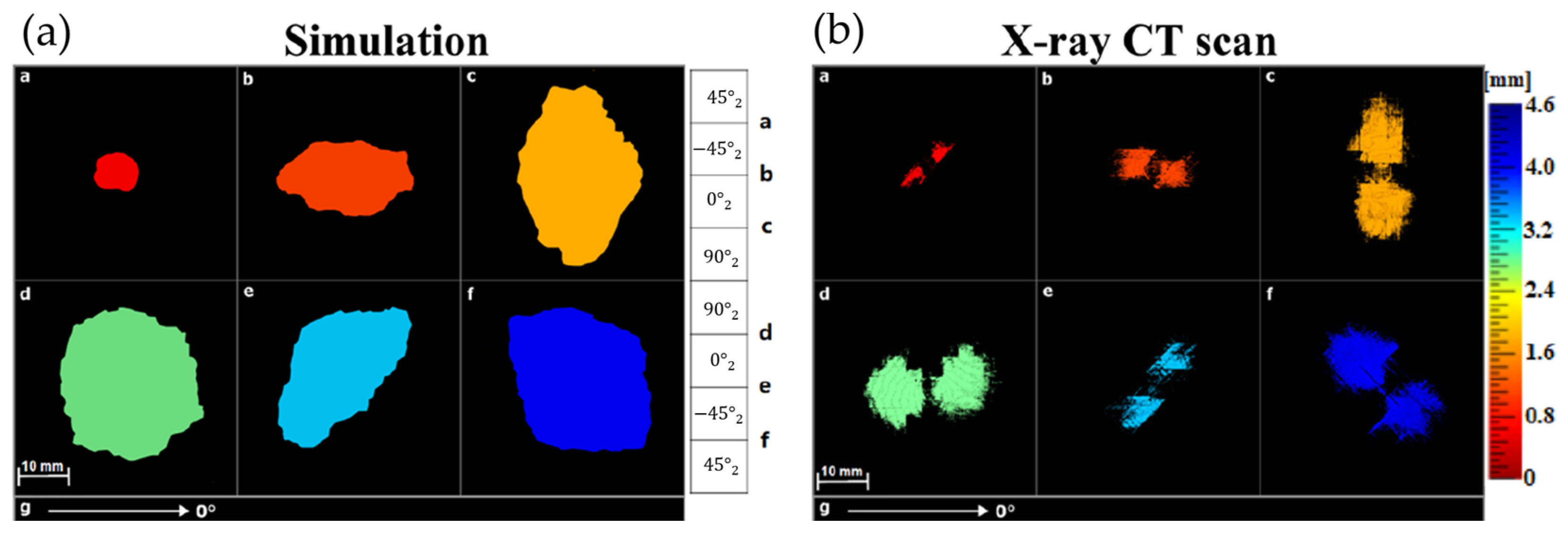
  159. Kourra, N.; Warnett, J.M.; Attridge, A.; Kiraci, E.; Gupta, A.; Barnes, S.; Williams, M.A. Metrological study of CFRP drilled holes with x-ray computed tomography. Int. J. Adv. Manuf. Technol. 2015, 78, 2025–2035. [Google Scholar] [CrossRef]
  160. De Chiffre, L.; Carmignato, S.; Kruth, J.-P.; Schmitt, R.; Weckenmann, A. Industrial applications of computed tomography. CIRP Ann. 2014, 63, 655–677. [Google Scholar] [CrossRef]
  161. Pomarede, P.; Meraghni, F.; Peltier, L.; Delalande, S.; Declercq, N.F. Damage evaluation in woven glass reinforced polyamide 6.6/6 composites using ultrasound phase-shift analysis and X-ray tomography. J. Nondestruct. Eval. 2018, 37, 12. [Google Scholar] [CrossRef]
  162. Carmignato, S. Accuracy of industrial computed tomography measurements: Experimental results from an international comparison. CIRP Ann. 2012, 61, 491–494. [Google Scholar] [CrossRef]
  163. Dilonardo, E.; Nacucchi, M.; De Pascalis, F.; Zarrelli, M.; Giannini, C. High resolution X-ray computed tomography: A versatile non-destructive tool to characterize CFRP-based aircraft composite elements. Compos. Sci. Technol. 2020, 192, 108093. [Google Scholar] [CrossRef]
  164. Kamali, G.; Ashokkumar, N.; Sugash, K.; Magesh, V. Advanced Composite Materials of the Future in Aerospace Engineering. Int. J. Res. Appl. Sci. Eng. Technol. 2017, 5, 610–614. [Google Scholar] [CrossRef]
  165. Vavilov, V.P. Physical Basics of Thermal Techniques of Nondestructive Evaluation. In Handbook of Advanced Nondestructive Evaluation, 1st ed.; Ida, N., Meyendorf, N., Eds.; Springer: Cham, Switzerland, 2019; pp. 1349–1369. [Google Scholar] [CrossRef]
  166. Ciampa, F.; Mahmoodi, P.; Pinto, F.; Meo, M. Recent Advances in Active Infrared Thermography for Non-Destructive Testing of Aerospace Components. Sensors 2018, 18, 609. [Google Scholar] [CrossRef]
  167. Padiyar, M.J.; Zanotti Fragonara, L.; Petrunin, I.; Raposo, J.; Tsourdos, A.; Gray, I.; Farmaki, S.; Exarchos, D.; Matikas, T.E.; Dassios, K.G. Fast, Accurate, and Reliable Detection of Damage in Aircraft Composites by Advanced Synergistic Infrared Thermography and Phased Array Techniques. Appl. Sci. 2021, 11, 2778. [Google Scholar] [CrossRef]
  168. Katnam, K.B.; Da Silva, L.F.M.; Young, T.M. Bonded repair of composite aircraft structures: A review of scientific challenges and opportunities. Prog. Aerosp. Sci. 2013, 61, 26–42. [Google Scholar] [CrossRef]
  169. Roth, D.J.; Bodis, J.R.; Bishop, C.C. Technical Memorandum; National Aeronautics and Space Administration: Cleveland, OH, USA, 1995.
  170. Proença, C.; Morais, P.; Salgueiro, F.; Correia, B.; Lopez, A.; Kneissl, C.; Petkov, T. Application of Non-destructive Testing in Quality Control of Manufactured Aluminium Metal Matrix Composite Components for the Automotive Industry. Res. Rev. J. Nondestruct. Test. 2023, 1. [Google Scholar] [CrossRef] [PubMed]
  171. Sasikumar, T.; Singh, R.R.B. Evaluating the mechanical characteristics of Al/SiC metal matrix composites (MMC) using Infrared thermographic Images. In Proceedings of the 1st QIRT Asia Conference on Quantitative Infrared Thermography, Mahabalipuram, India, 6–10 July 2016. [Google Scholar] [CrossRef]
  172. Dassios, K.G.; Matikas, T.E. Assessment of Fatigue Damage and Crack Propagation in Ceramic Matrix Composites by Infrared Thermography. Ceramics 2019, 2, 393–406. [Google Scholar] [CrossRef]
  173. Singh, R.R.B.; Sasikumar, T.; Suresh, S.; Ramanan, G. A novel detection of defects in Al–SiC composite by active pulsed infrared thermography using data and image processing. Trans. Indian Inst. Met. 2020, 73, 2767–2783. [Google Scholar] [CrossRef]
  174. Duan, Y.; Zhang, H.; Maldague, X.P.V.; Ibarra-Castanedo, C.; Servais, P.; Genest, M.; Sfarra, S.; Meng, J. Reliability Assessment of Pulsed Thermography and Ultrasonic Testing for Impact Damage of CFRP Panels. NDT E Int. 2019, 102, 77–83. [Google Scholar] [CrossRef]
  175. Sy, B.L.; Oguamanam, D.; Bougherara, H. Impact Response of a New Kevlar/Flax/Epoxy Hybrid Composite Using Infrared Thermography and High-Speed Imaging. Compos. Struct. 2022, 280, 114885. [Google Scholar] [CrossRef]
  176. Yang, B.; Huang, Y.; Cheng, L. Defect Detection and Evaluation of Ultrasonic Infrared Thermography for Aerospace CFRP Composites. Infrared Phys. Technol. 2013, 60, 166–173. [Google Scholar] [CrossRef]
  177. Moskovchenko, A.; Vavilov, V.; Švantner, M.; Muzika, L.; Houdková, Š. Active IR Thermography Evaluation of Coating Thickness by Determining Apparent Thermal Effusivity. Materials 2020, 13, 4057. [Google Scholar] [CrossRef]
  178. Hung, Y.Y.; Ho, H.P. Shearography: An optical measurement technique and applications. Mater. Sci. Eng. R Rep. 2005, 49, 61–87. [Google Scholar] [CrossRef]
  179. Okafor, A.C.; Otieno, A.W.; Dutta, A.; Rao, V.S. Detection and characterization of high-velocity impact damage in advanced composite plates using multi-sensing techniques. Compos. Struct. 2001, 54, 289–297. [Google Scholar] [CrossRef]
  180. Michael, K.; Wolfgang, O.; Jueptner, W.P.O. Advanced shearographic system for nondestructive testing of industrial and artwork components. In Lasers in Material Processing and Manufacturing; The International Society for Optical Engineering/Proceedings of SPIE; SPIE: Bellingham, WA, USA, 2002. [Google Scholar]
  181. Hung, Y.Y. Applications of digital shearography for testing of composite structures. Compos. Part B Eng. 1999, 30, 765–773. [Google Scholar] [CrossRef]
  182. Newman, J.W. Aerospace NDT with Advanced Laser Shearography. In Proceedings of the 17th World Conference on Nondestructive Testing, Shanghai, China, 25–28 October 2008; pp. 25–28. [Google Scholar]
  183. Findeis, D.; Gryzagoridis, J. Digital Shearography and Vibration Excitation for NDT of Aircraft Components. AIP Conf. Proc. 2014, 1600, 33–38. [Google Scholar] [CrossRef]
  184. Hung, Y.Y.; Luo, W.D.; Lin, L.; Shang, H.M. Evaluating the soundness of bonding using shearography. Compos. Struct. 2000, 50, 353–362. [Google Scholar] [CrossRef]
  185. Lee, J.-R.; Molimard, J.; Vautrin, A.; Surrel, Y. Application of grating shearography and speckle shearography to mechanical analysis of composite material. Compos. Part A Appl. Sci. Manuf. 2004, 35, 965–976. [Google Scholar] [CrossRef]
  186. Taillade, F.; Quiertant, M.; Benzarti, K.; Aubagnac, C. Shearography and pulsed stimulated infrared thermography applied to a nondestructive evaluation of FRP strengthening systems bonded on concrete structures. Constr. Build. Mater. 2011, 25, 568–574. [Google Scholar] [CrossRef]
  187. Angelis, G.D.; Meo, M.; Almond, D.P.; Pickering, S.G.; Angioni, S.L. A new technique to detect defect size and depth in composite structures using digital shearography and unconstrained optimization. NDT E Int. 2012, 45, 91–96. [Google Scholar] [CrossRef]
  188. Murri, W.J.; Sermon, B.W.; Andersen, R.N.; Martinez, L.A.; Van der Heiden, E.J.; Garner, C.A. Defects in Thick Composites and Some Methods to Locate Them. In Review of Progress in Quantitative Nondestructive Evaluation; Springer: New York, NY, USA, 1991; pp. 583–1590. [Google Scholar]
  189. Hung, Y.Y.; Yang, L.X.; Huang, Y.H. 5-Non-destructive evaluation (NDE) of composites: Digital shearography. In Non-Destructive Evaluation (NDE) of Polymer Matrix Composites; Dans Elsevier eBooks; Woodhead Publishing: Cambridge, UK, 2013; pp. 84–115. [Google Scholar]
  190. Lomov, S.V.; Ivanov, D.S.; Verpoest, I.; Zako, M.; Kurashiki, T.; Nakai, H.; Molimard, J.; Vautrin, A. Full-field strain measurements for validation of meso-FE analysis of textile composites. Compos. Part A Appl. Sci. Manuf. 2008, 39, 1218–1231. [Google Scholar] [CrossRef]
  191. Lee, J.-R.; Lee, D.-J.; Yoon, J.-S.; Kim, J.-S.; Vautrin, A. Investigation of shear distance in Michelson interferometer-based shearography for mechanical characterization. Meas. Sci. Technol. 2008, 19, 115303. [Google Scholar] [CrossRef]
  192. Gryzagoridis, J.; Findeis, D. Benchmarking shearographic NDT for composites. Insight-Non-Destr. Test. Cond. Monit. 2008, 50, 249–252. [Google Scholar] [CrossRef]
  193. Newman, J.W. Holographic and shearographic NDT applications in aerospace manufacturing. Mater. Eval. 2005, 63, 747–750. [Google Scholar]
  194. Gregory, R. Production inspection of aerospace composites using laser shearography. Insight 2002, 44, 220–223. [Google Scholar]
  195. Zheng, X.; Fang, S.; Guo, B.; Sia, B.; Yang, L. Development of Simultaneous Dual-Resolution Digital Holography System. Appl. Sci. 2023, 13, 2856. [Google Scholar] [CrossRef]
  196. Mahmud, M.S.; Naydenova, I.; Toal, V. Implementation of phase-only modulation utilizing a twisted nematic liquid crystal spatial light modulator. J. Opt. A Pure Appl. Opt. 2008, 10, 085007. [Google Scholar] [CrossRef]
  197. Sun, F.; Wang, Y.; Yan, P.; Zhao, Q.; Yang, L. The application of SLM in shearography detecting system. Opt. Lasers Eng. 2019, 114, 90–94. [Google Scholar] [CrossRef]
  198. Zhao, Q.; Dan, X.; Sun, F.; Wang, Y.; Wu, S.; Yang, L. Digital shearography for NDT: Phase measurement technique and recent developments. Appl. Sci. 2018, 8, 2662. [Google Scholar] [CrossRef]
  199. Del Rey Castillo, E.; Allen, T.; Henry, R.; Griffith, M.; Ingham, J. Digital image correlation (DIC) for measurement of strains and displacements in coarse, low volume-fraction FRP composites used in civil infrastructure. Compos. Struct. 2019, 212, 43–57. [Google Scholar] [CrossRef]
  200. Pan, B. Digital image correlation for surface deformation measurement: Historical developments, recent advances and future goals. Meas. Sci. Technol. 2018, 29, 082001. [Google Scholar] [CrossRef]
  201. Peters, W.H.; Ranson, W.F. Digital imaging techniques in experimental stress analysis. Opt. Eng. 1982, 21, 427–431. [Google Scholar] [CrossRef]
  202. Chu, T.C.; Ranson, W.F.; Sutton, M.A. Applications of digital-image-correlation techniques to experimental mechanics. Exp. Mech. 1985, 25, 232–244. [Google Scholar] [CrossRef]
  203. Zarouchas, D.; Van Hemelrijck, D. Mechanical characterization and damage assessment of thick adhesives for wind turbine blades using acoustic emission and digital image correlation techniques. J. Adhes. Sci. Technol. 2014, 28, 1500–1516. [Google Scholar] [CrossRef]
  204. Lim, C.; Jeong, Y.; Limkantanyu, S.; Kwon, M. Strain Measuring of Composite Grid Using Digital Image Correlation. Adv. Mater. Sci. Eng. 2022, 2022, 6041887. [Google Scholar] [CrossRef]
  205. Tekieli, M.; De Santis, S.; De Felice, G.; Kwiecień, A.; Roscini, F. Application of Digital Image Correlation to composite reinforcements testing. Compos. Struct. 2017, 160, 670–688. [Google Scholar] [CrossRef]
  206. Pour, A.F.; Nguyen, G.D.; Vincent, T.; Ozbakkaloglu, T. Investigation of the compressive behavior and failure modes of unconfined and FRP-confined concrete using digital image correlation. Compos. Struct. 2020, 252, 112642. [Google Scholar] [CrossRef]
  207. Spencer, R.; Hassen, A.A.; Baba, J.; Lindahl, J.; Love, L.; Kunc, V.; Babu, S.; Vaidya, U. An innovative digital image correlation technique for in-situ process monitoring of composite structures in large scale additive manufacturing. Compos. Struct. 2021, 276, 14545. [Google Scholar] [CrossRef]
  208. Pisonero, J.; López-Rebollo, J.; García-Martín, R.; Rodríguez-Martín, M.; Sánchez-Aparicio, L.J.; Muñoz-Nieto, A. A comparative study of 2D and 3D digital image correlation approaches for the characterization and numerical analysis of composite materials. IEEE Access 2021, 9, 160675–160687. [Google Scholar] [CrossRef]
  209. Dai, Y.-T.; Wang, H.-T.; Ge, T.-Y.; Wu, G.; Wan, J.-X.; Cao, S.-Y.; Yang, F.-J.; He, X.-Y. Stereo-digital image correlation in the behavior investigation of CFRP-steel composite members. Steel Compos. Struct 2017, 23, 727–736. [Google Scholar] [CrossRef]
  210. Biscaia, H.C.; Franco, N.; Chastre, C. Development of a simple bond-slip model for joints monitored with the DIC technique. Arch. Civ. Mech. Eng. 2018, 18, 1535–1546. [Google Scholar] [CrossRef]
  211. Ghiassi, B.; Xavier, J.; Oliveira, D.V.; Lourenço, P.B. Application of digital image correlation in investigating the bond between FRP and masonry. Compos. Struct. 2013, 106, 340–349. [Google Scholar] [CrossRef]
  212. Arora, H.; Hooper, P.A.; Dear, J.P. Dynamic Response of Full-Scale Sandwich Composite Structures Subject to Air-Blast Loading. Compos. Part A Appl. Sci. Manuf. 2011, 42, 1651–1662. [Google Scholar] [CrossRef]
  213. Rims, J.; Xiao, C. Review of digital image correlation application to large-scale composite structure testing. Compos. Struct. 2021, 271, 114143. [Google Scholar] [CrossRef]
  214. Annett, M.; Littell, J. Overview of the Transport Rotorcraft Airframe Crash Testbed (TRACT) Full Scale Crash Tests; NASA Langley Research Center: Hampton, VA, USA, 2016.
  215. Mehdikhani, M.; Aravand, M.A.; Sabuncuoglu, B.; Callens, M.G.; Lomov, S.V.; Gorbatikh, L. Digital image correlation and finite element analysis applied to fiber-reinforced composites at the micro-scale. In Proceedings of the 20th International Conference on Composite Materials, Copenhagen, Denmark, 19–24 July 2015. [Google Scholar]
  216. Hao, Z.; Ji, X.; Deng, L.; Ke, H.; Liu, L. Measurement of multiple mechanical properties for polymer composites using digital image correlation at elevated temperatures. Mater. Des. 2021, 198, 109349. [Google Scholar] [CrossRef]
  217. Montesano, J.; Selezneva, M.; Levesque, M.; Fawaz, Z. Modeling fatigue damage evolution in polymer matrix composite structures and validation using in-situ digital image correlation. Compos. Struct. 2015, 125, 354–361. [Google Scholar] [CrossRef]
  218. Guessasma, S.; Nouri, H.; Belhabib, S. Digital Image Correlation and Finite Element Computation to Reveal Mechanical Anisotropy in 3D Printing of Polymers. Materials 2022, 15, 8382. [Google Scholar] [CrossRef]
  219. Peeters, D.; Lomov, S.V.; Wevers, M. Digital Image Correlation Analysis of Strain Fields in Fibre-Reinforced Polymer–Matrix Composite under ±45° off-Axis Tensile Testing. J. Compos. Mater. 2020, 54, 2921–2932. [Google Scholar]
  220. Whitlow, T.; Jones, E.; Przybyla, C. In-situ damage monitoring of a SiC/SiC ceramic matrix composite using acoustic emission and digital image correlation. Compos. Struct. 2016, 158, 245–251. [Google Scholar] [CrossRef]
  221. Rajan, V.P.; Rossol, M.N.; Zok, F.W. Optimization of digital image correlation for high-resolution strain mapping of ceramic composites. Exp. Mech. 2012, 52, 1407–1421. [Google Scholar] [CrossRef]
  222. Mieloszyk, M.; Majewska, K.; Ostachowicz, W. Application of embedded fibre Bragg grating sensors for structural health monitoring of complex composite structures for marine applications. Mar. Struct. 2021, 76, 102903. [Google Scholar] [CrossRef]
  223. Matveenko, V.; Kosheleva, N.; Serovaev, G.; Fedorov, A. Analysis of Reliability of Strain Measurements Made with the Fiber Bragg Grating Sensor Rosettes Embedded in a Polymer Composite Material. Sensors 2021, 21, 5050. [Google Scholar] [CrossRef]
  224. Fedorov, A.Y.; Kosheleva, N.A.; Matveenko, V.P.; Serovaeva, G.S. Strain measurement and stress analysis in the vicinity of a fiber Bragg grating sensor embedded in a composite material. Compos. Struct. 2020, 239, 111844. [Google Scholar] [CrossRef]
  225. Garnier, C.; Pastor, M.-L.; Eyma, F.; Lorrain, B. The detection of aeronautical defects in situ on composite structures using Non Destructive Testing. Compos. Struct. 2011, 93, 1328–1336. [Google Scholar] [CrossRef]
  226. Mathieu, P.; Alain, B.; Monchalin, J.-P. Adhesive bond testing of carbon–epoxy composites by laser shockwave. J. Phys. D Appl. Phys. 2010, 44, 034012. [Google Scholar] [CrossRef]
  227. Ecault, R.; Boustie, M.; Touchard, F.; Pons, F.; Berthe, L.; Chocinski-Arnault, L.; Ehrhart, B.; Bockenheimer, C. Damage of composite materials by use of laser driven shock waves. Compos. Part A Appl. Sci. Manuf. 2013, 53, 54–64. [Google Scholar] [CrossRef]
  228. Barus, M.; Welemane, H.; Nassiet, V.; Pastor, M.-L.; Cantarel, A.; Collombet, F.; Crouzeix, L.; Grunevald, Y.H. NDT-based design of joint material for the detection of bonding defects by infrared thermography. NDT E Int. 2018, 93, 157–163. [Google Scholar] [CrossRef]
  229. Li, Y.; Yao, K.; Li, X. An ultrasonic signal reconstruction algorithm of multilayer composites in non-destructive testing. Appl. Acoust. 2022, 186, 108461. [Google Scholar] [CrossRef]
  230. Tao, N.; Anisimov, A.G.; Groves, R.M. FEM-assisted shearography with spatially modulated heating for non-destructive testing of thick composites with deep defects. Compos. Struct. 2022, 297, 115980. [Google Scholar] [CrossRef]
  231. Bustamante, L.; Jeyaprakash, N.; Yang, C.-H. Hybrid laser and air-coupled ultrasonic defect detection of aluminium and CFRP plates by means of Lamb mode. Results Phys. 2020, 19, 103438. [Google Scholar] [CrossRef]
  232. Tao, N.; Anisimov, A.G.; Groves, R.M. Towards safe shearography inspection of thick composites with controlled surface temperature heating. NDT E Int. 2023, 139, 102907. [Google Scholar] [CrossRef]
  233. Zhang, L.; Tham, Z.W.; Chen, Y.F.; Tan, C.Y.; Cui, F.; Mutiargo, B.; Ke, L. Defect imaging in carbon fiber composites by acoustic shearography. Compos. Sci. Technol. 2022, 223, 109417. [Google Scholar] [CrossRef]
  234. Yasuda, Y.; Cappabianco, F.; Martins, L.E.; Gripp, J.A.B. Aircraft visual inspection: A systematic literature review. Comput. Ind. 2022, 141, 103695. [Google Scholar] [CrossRef]
  235. He, Y.; Tian, G.; Pan, M.; Chen, D. Impact evaluation in carbon fiber reinforced plastic (CFRP) laminates using eddy current pulsed thermography. Compos. Struct. 2014, 109, 1–7. [Google Scholar] [CrossRef]
  236. Jordan, S.; Moore, J.; Hovet, S.; Box, J.; Perry, J.; Kirsche, K.; Lewis, D.; Tse, Z.T.H. State-of-the-art technologies for UAV inspections. IET Radar, Sonar & Navigation. IET Radar Sonar Navig. 2018, 12, 151–164. [Google Scholar] [CrossRef]
  237. Cazzato, D.; Olivares-Mendez, M.A.; Sanchez-Lopez, J.L.; Voos, H. Vision-based aircraft pose estimation for UAVs autonomous inspection without fiducial markers. In Proceedings of the IECON 2019-45th Annual Conference of the IEEE Industrial Electronics Society, Lisbon, Portugal, 14–17 October 2019; pp. 5642–5648. [Google Scholar] [CrossRef]
  238. Mattar, R.A.; Kalai, R. Development of a Wall-Sticking Drone for Non-Destructive Ultrasonic and Corrosion Testing. Drones 2018, 2, 8. [Google Scholar] [CrossRef]
  239. Lin, B.-S.; Cheng, J.-S.; Liao, H.-C.; Yang, L.-W.; Yang, T.; Chen, K.-C. Improvement of Multi-Lines Bridge Defect Classification by Hierarchical Architecture in Artificial Intelligence Automatic Defect Classification. In Proceedings of the 2020 International Symposium on Semiconductor Manufacturing (ISSM), Tokyo, Japan, 15–16 December 2020; pp. 1–4. [Google Scholar] [CrossRef]
  240. Bircher, A.; Alexis, K.; Burri, M.; Oettershagen, P.; Omari, S.; Mantel, T. Structural inspection path planning via iterative viewpoint resampling with application to aerial robotics. In Proceedings of the IEEE International Conference on Robotics and Automation (ICRA), Seattle, WA, USA, 26–30 May 2015; pp. 6423–6430. [Google Scholar] [CrossRef]
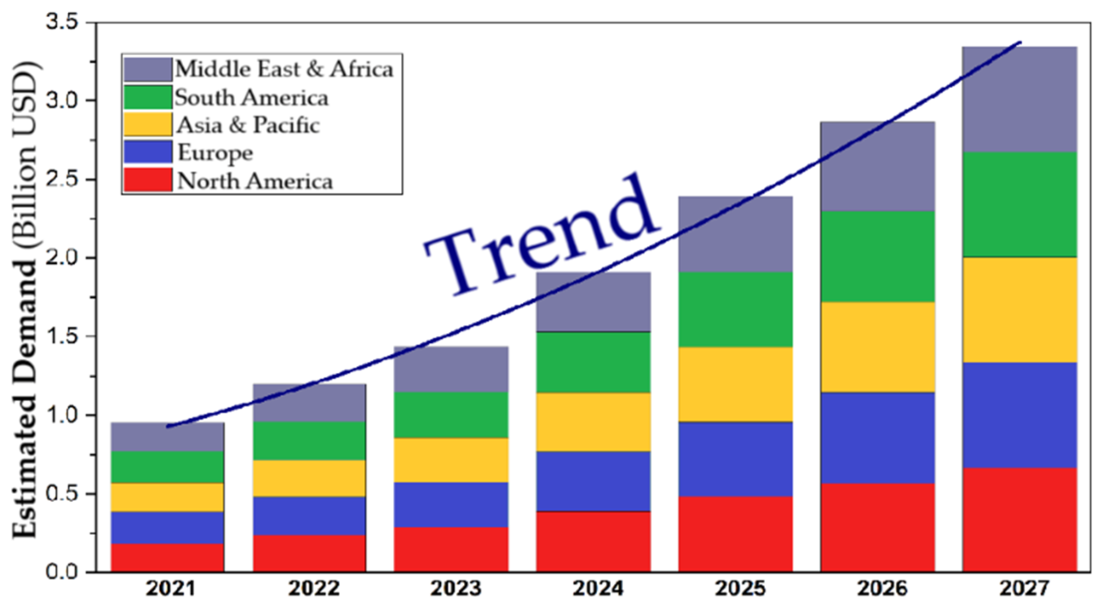
  241. Global Composites Testing Market—Industry Trends and Forecast to 2030. Available online: https://www.databridgemarketresearch.com/reports/global-composites-testing-market (accessed on 24 June 2024).
  242. Elenchezhian, M.R.P.; Vadlamudi, V.; Raihan, R.; Reifsnider, K.; Reifsnider, E. Artificial intelligence in real-time diagnostics and prognostics of composite materials and its uncertainties—A review. Smart Mater. Struct. 2021, 30, 083001. [Google Scholar] [CrossRef]
  243. Baldwin, J. Composite testing gets smarter. Adv. Mech. Eng. 2020, 12. [Google Scholar] [CrossRef]
  244. Gupta, R.; Mitchell, D.; Blanche, J.; Harper, S.; Tang, W.; Pancholi, K.; Baines, L.; Bucknall, D.G.; Flynn, D. A review of sensing technologies for non-destructive evaluation of structural composite materials. J. Compos. Sci. 2021, 5, 319. [Google Scholar] [CrossRef]
  245. Sause, M.G.R.; Gribov, A.; Unwin, A.R.; Horn, S. Pattern recognition approach to identify natural clusters of acoustic emission signals. Pattern Recognit. Lett. 2012, 33, 17–23. [Google Scholar] [CrossRef]
  246. El Guerjouma, R.; Baboux, J.C.; Ducret, D.; Godin, N.; Guy, P.; Huguet, S.; Jayet, Y.; Monnier, T. Non-destructive evaluation of damage and failure of fibre reinforced polymer composites using ultrasonic waves and acoustic emission. Adv. Eng. Mater. 2001, 3, 601–608. Available online: https://hal.science/hal-00573986 (accessed on 23 December 2024). [CrossRef]
  247. Liu, C.; Dobson, J.; Cawley, P. Efficient generation of receiver operating characteristics for the evaluation of damage detection in practical structural health monitoring applications. Proc. R. Soc. A Math. Phys. Eng. Sci. 2017, 473, 20160736. [Google Scholar] [CrossRef]
  248. Lu, Y.; Ye, L.; Su, Z.; Zhou, L.; Cheng, L. Artificial neural network (ANN)-based crack identification in aluminum plates with Lamb wave signals. J. Intell. Mater. Syst. Struct. 2009, 20, 39–49. [Google Scholar] [CrossRef]
  249. Harley, J.B.; Sparkman, D. Machine learning and NDE: Past, present, and future. AIP Conf. Proc. 2019, 2102, 090001. [Google Scholar] [CrossRef]
  250. Aldrin, J.C.; Forsyth, D.S. Demonstration of using signal feature extraction and deep learning neural networks with ultrasonic data for detecting challenging discontinuities in composite panels. AIP Conf. Proc. 2019, 2102, 020012. [Google Scholar]
  251. Ang, W.; Mitchell, D.; Blanche, J.; Gupta, R.; Flynn, D. Machine learning analysis of non-destructive evaluation data from radar inspection of wind turbine blades. In Proceedings of the 2021 IEEE International Conference on Sensing, Diagnostics, Prognostics, and Control (SDPC), Weihai, China, 13–15 August 2021; pp. 122–128. [Google Scholar] [CrossRef]
  252. Mitchell, D.; Blanche, J.; Zaki, O.; Roe, Z.; Kong, L.; Harper, S. Symbiotic system of systems design for safe and resilient autonomous robotics in offshore wind farms. IEEE Access 2021, 9, 141421–141452. [Google Scholar] [CrossRef]
  253. Blanche, J.; Lewis, H.; Couples, G.D.; Buckman, J.; Lenoir, N.; Tengattini, A. Dynamic fluid ingress detection in geomaterials using K-band frequency modulated continuous wave radar. IEEE Access 2020, 8, 111027–111041. [Google Scholar] [CrossRef]
  254. Blanche, J.; Mitchell, D.; Gupta, R.; Tang, A.; Flynn, D. Asset integrity monitoring of wind turbine blades with non-destructive radar sensing. In Proceedings of the 2020 11th IEEE Annual Information Technology, Electronics and Mobile Communication Conference (IEMCON), Vancouver, BC, Canada, 4–7 November 2020. [Google Scholar] [CrossRef]
  255. Kong, L.C.W.; Harper, S.; Mitchell, D.; Blanche, J.; Lim, T.; Flynn, D. Interactive digital twins framework for asset management through internet. In Proceedings of the 2020 IEEE Global Conference on Artificial Intelligence and Internet of Things (GCAIoT), Dubai, United Arab Emirates, 12–16 December 2020. [Google Scholar] [CrossRef]
  256. Gholizadeh, S. A review of non-destructive testing methods of composite materials. Procedia Struct. Integr. 2016, 1, 50–57. [Google Scholar] [CrossRef]
  257. Li, Q.; Kumar, A.; Kim, N.H.; Kuila, T.; Lau, K.; Lee, J.H. Effects of processing conditions of poly(methylmethacrylate) encapsulated liquid curing agent on the properties of self-healing composites. Compos. Part B Eng. 2013, 4, 6–15. [Google Scholar] [CrossRef]
  258. Kanu, N.J.; Gupta, E.; Vates, U.K.; Singh, G.K. Self-healing composites: A state-of-the-art review. Compos. Part A Appl. Sci. Manuf. 2019, 121, 474–486. [Google Scholar] [CrossRef]
  259. Islam, S.; Bhat, G. Progress and challenges in self-healing composite materials. Mater. Adv. 2021, 2, 1896–1926. [Google Scholar] [CrossRef]
  260. Toohey, K.S.; Sottos, N.R.; Lewis, J.A.; Moore, J.S.; White, S.R. Self-healing materials with microvascular networks. Nat. Mater. 2007, 6, 581–585. [Google Scholar] [CrossRef]
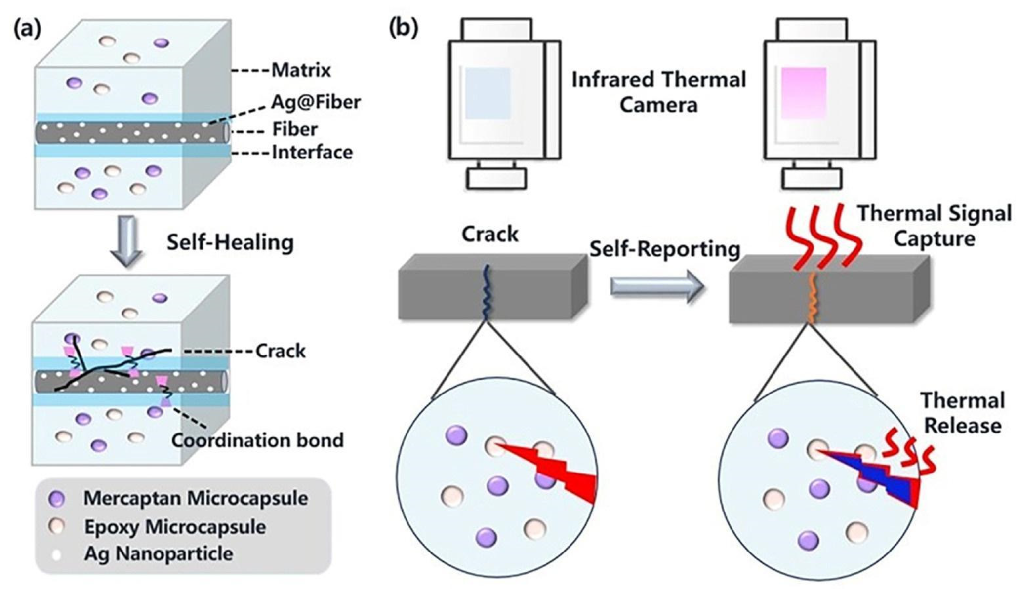
  261. Yuan, W.; Zhang, Z.; Li, Y.; Huang, Y.; Zhong, Z.; Hu, Z. Self-healing and in-situ real-time damage-reporting fiber-reinforced composite. Compos. Sci. Technol. 2024, 245, 110344. [Google Scholar] [CrossRef]
  262. Wang, B.; Zhong, S.; Lee, T.-L.; Fancey, K.S.; Mi, J. Non-destructive testing and evaluation of composite materials and structures: A state-of-the-art review. Adv. Mech. Eng. 2020, 12, 1–28. [Google Scholar] [CrossRef]
  263. Schmidt, C.; Hocke, T.; Denkena, B. Artificial intelligence for non-destructive testing of CFRP prepreg materials. Prod. Eng. 2019, 13, 617–626. [Google Scholar] [CrossRef]
  264. Ahmed, O.; Wang, X.; Tran, M.-V.; Ismadi, M.-Z. Advancements in fiber-reinforced polymer composite materials damage detection methods: Towards achieving energy-efficient SHM systems. Compos. Part B Eng. 2021, 223, 109136. [Google Scholar] [CrossRef]
  265. Zhu, B. Nondestructive Testing Method of Engineering Material Defects Based on Artificial Intelligence Algorithm. In Proceedings of the 2nd International Conference on 3D Immersion, Interaction and Multi-sensory Experiences, Chengdu, China, 27–29 June 2023; pp. 302–307. [Google Scholar] [CrossRef]
  266. Pitarresi, G. Lock-In Signal Post-Processing Techniques in Infrared Thermography for Materials Structural Evaluation. Exp. Mech. 2013, 55, 667–680. [Google Scholar] [CrossRef]
  267. D’Accardi, E.; Dell’Avvocato, G.; Palumbo, D.; Galietti, U. Limits and Advantages in Using Low-Cost Microbolometric IR-Camera in Lock-In Thermography for CFRP Applications. In Thermosense: Thermal Infrared Applications XLIII; SPIE: Bellingham, WA, USA, 2021; pp. 151–165. [Google Scholar] [CrossRef]
  268. Maierhofer, C.; Röllig, M.; Krankenhagen, R.; Myrach, P. Comparison of Quantitative Defect Characterization Using Pulse-Phase and Lock-In Thermography. Appl. Opt. 2016, 55, 76–86. [Google Scholar] [CrossRef]
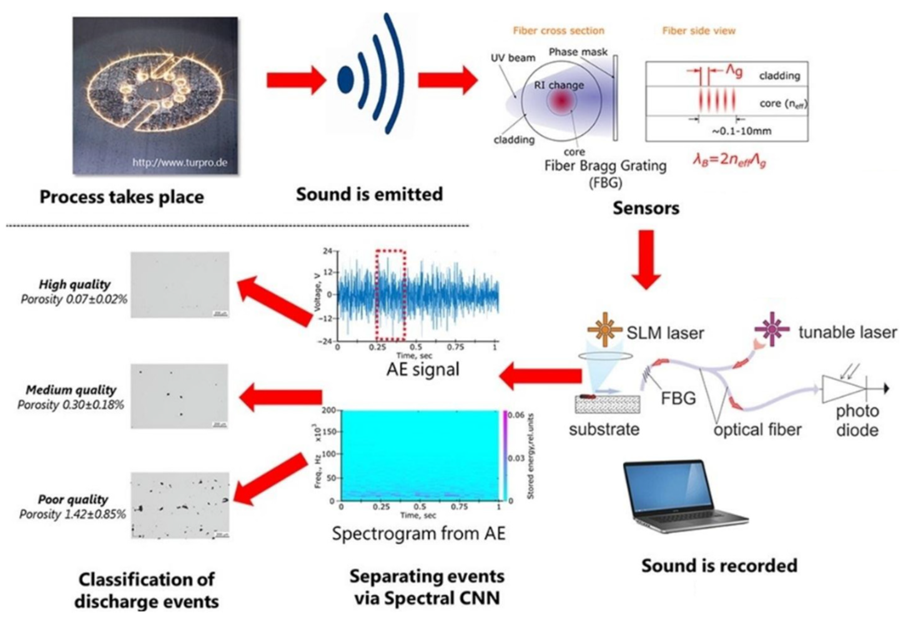
  269. Shevchik, S.A.; Kenel, C.; Leinenbach, C.; Wasmer, K. Acoustic Emission for In Situ Quality Monitoring in Additive Manufacturing Using Spectral Convolutional Neural Networks. Addit. Manuf. 2018, 21, 598–604. [Google Scholar] [CrossRef]
  270. Tavares, A.; Di Lorenzo, E.; Peeters, B.; Coppotelli, G.; Silvestre, N. Damage Detection in Lightweight Structures Using Artificial Intelligence Techniques. Exp. Tech. 2021, 45, 389–410. [Google Scholar] [CrossRef]
  271. Patro, S.; Mahapatra, T.R.; Dash, S.; Murty, V.K. Artificial intelligence techniques for fault assessment in laminated composite structures: A review. In Proceedings of the 3rd International Conference on Design and Manufacturing Aspects for Sustainable Energy, Hyderabad, India, 24–26 December 2021; p. 0183. [Google Scholar] [CrossRef]
  272. Das, M.; Sahu, S.; Parhi, D.R. A Review of Application of Composite Materials for Aerospace Structures and Its Damage Detection Using Artificial Intelligence Techniques. In Proceedings of the International Conference on Artificial Intelligence in Manufacturing & Renewable Energy, Bhubaneswar, India, 25–26 October 2019. [Google Scholar] [CrossRef]
Figure 2. Composite laminate and the evolution of damage based on the material lifetime [77].
Ndt 03 00003 g002
Figure 3. Microscopic images showing damage mechanisms of (A) fiber breakage due to pull-out and (B) interfacial debonding between the matrix and the fiber, modified from [89].
Ndt 03 00003 g003
Figure 4. High-resolution micrograph showing the damages on MMCs, (A) a surface fracture fiber–matrix interface in a titanium matrix composite reinforced with SiC fibers (modified from [90]), and (B) presence of voids due to loading in an AlSi matrix reinforced with SiC (modified from [92]).
Ndt 03 00003 g004
Figure 5. SEM images of corrosion damage in metal matrix composites: (a) uncoated titanium components displaying surface roughness and corrosion; (b) cross-sectional view highlighting the corrosion product layer formed after exposure to a corrosive environment, modified from [95].
Ndt 03 00003 g005
Figure 6. Surface (a) and cross-section (b) SEM images of the c-AlPO₄-SiCw-mullite coating with 20 wt.% c-AlPO₄ applied on SiC–C/SiC composites. The surface image (a) highlights the morphology of the coating, while the cross-section image (b) reveals cracks formed after 210 h of oxidation at 1773 K in air. Adapted from [100].
Ndt 03 00003 g006
Figure 7. Mechanisms of matrix cracking under tensile test: (a) typical stress–strain curve of a unidirectional CMC; (b) schematic representation of crack–tip and crack–wake debonding for the same material. Modified from [103].
Ndt 03 00003 g007
Figure 8. A proposed workflow for detecting and analyzing voids and cracks in a SiC [108]. The arrow indicates a magnified region of a smaller number of pores with larger sizes.
Ndt 03 00003 g008
Figure 9. Ultrasonic C-scan (a) and B-scan (b) were performed on a specimen following the application of an impact energy of 40 J. The C-scan (a) provides a planar view showing the lateral distribution of damage, including the impact site, delaminated areas, and manufacturing defects. The B-scan (b) shows a cross-sectional depth profile of the same region, illustrating the top and bottom laminas and the internal delamination. Together, the views provide a spatial representation of the impact damage. Modified from [135].
Ndt 03 00003 g009
Figure 10. Experimental setup was designed for the evaluation of capability and sensitivity, encompassing both PAUT (a) and SEUT (b). Modified from [136].
Ndt 03 00003 g010
Figure 11. Response signals for GFRP: (a) SEUT method and (b) PAUT method (the parameters used in the testing include a frequency of 1.5 MHz, a thickness of 25 mm, a hole diameter of 0.8 mm, and a hole depth of 12 mm). Modified from [136].
Ndt 03 00003 g011
Figure 12. Results from mechanical test of a CMC monitored with AE, with signal classification and damage identification. Modified from [101].
Ndt 03 00003 g012
Figure 13. Classification of damage by AE signal feature for polymer composite materials, (a) peak frequency, (b) amplitude. Modified from [142].
Ndt 03 00003 g013
Figure 15. Monitoring of machining processes using AE: (a) drilling, modified from [152]; (b) milling, adapted from [144].
Ndt 03 00003 g015
Figure 16. Optical microscopy images at different magnifications illustrate (a) the surface and (b) the cross-sectional view of the sandwich panel. Modified from [163].
Ndt 03 00003 g016
Figure 17. 3D renderings of the composite sample before (a) and after (b) foam masking. Modified from [163].
Ndt 03 00003 g017
Figure 18. Grayscale histograms before/after foam masking. Before masking (a), two peaks represent pores and combined CFRP–foam. After masking (b), a new peak appears for the background, with remaining peaks corresponding to pores and CFRP. Modified from [163].
Ndt 03 00003 g018
Figure 19. Typical damage maps in the X–Y plane from (a) the experimental ultrasonic C-scan technique, (b) the experimental X-ray CT technique, and (c) the numerical modeling predictions. Modified from [12].
Ndt 03 00003 g019
Figure 20. Comparison of interlaminar damage between blocking plies obtained from (a) numerical simulation and (b) experimental X-ray CT scan. Modified from [12].
Ndt 03 00003 g020
Figure 21. Progression of thermal response for the CMC during fatigue testing. Modified from [172].
Ndt 03 00003 g021
Figure 22. Stages of visualization of a defect in Al MMC using APIRL. Modified from [174].
Ndt 03 00003 g022
Figure 23. Detection capabilities of impact damage in CFRP of PTT and UT. Modified from [175].
Ndt 03 00003 g023
Figure 24. Thermal response of the hybrid PMC to impact damage. Modified from [175].
Ndt 03 00003 g024
Figure 25. Specimen sides and the different domains used for analyses of defects. Adapted from [176].
Ndt 03 00003 g025
Figure 26. Measurement of coating thickness by active IRT, from [177].
Ndt 03 00003 g026
Figure 27. Detection and magnification of a defect using hologram. (a) Wide-field hologram showing the overall fringe pattern and the location of the defect (circled in red). (b) Magnified-in hologram highlighting the detailed morphology of the defect [195].
Ndt 03 00003 g027
Figure 28. Phase map under large and small fields of view. (a) Phase map of large field of view, and (b) phase map of small field of view [195].
Ndt 03 00003 g028
Figure 29. (a) The new shearography system with a spatial light modulator; (b) experimental result of a thimble-loaded aluminum plate; (c) experimental result of a composite plate with three flaws, modified [197].
Ndt 03 00003 g029
Figure 30. (a) Preparation of the helicopter fuselage with random speckle patterns for DIC analysis; (b) Comparison of the helicopter fuselage pre-impact and post-impact conditions, without applying DIC analysis; (c) Deformation fields derived through DIC analysis, illustrating structural changes resulting from the impact event. Adapted from [213,214].
Ndt 03 00003 g030
Figure 31. Correlation between DIC and AE monitoring of mechanical tests. (a) DIC snapshot of the tensile specimen, (b) AE snapshot highlighting the detected events, and (c) Combined stress profile and corresponding AE events during the test. Adapted from [220].
Ndt 03 00003 g031
Figure 32. Multi-scale analysis of strain distribution and crack propagation in SiC/SiC composite: (a) Displacement field overlaid on the sectioning plane; (b) Optical micrograph of the sectioned area highlighting the internal structure of the CMC; (c) Electron micrograph zoom-in on a large central crack within the composite. Red arrows denote fiber breaks, and blue arrows denote cracks in the paint. Adapted from [221].
Ndt 03 00003 g032
Figure 33. Region-specific market demand projections are provided for the non-destructive evaluation (NDE) of composite materials spanning the years 2021–2027, accompanied by a visual representation of the trend line superimposed on the data. Modified from [244].
Ndt 03 00003 g033
Figure 34. Schematic the self-healing composite with integrated damage detection. (a) Initial composite structure with microcapsules and Ag nanoparticles at the fiber-matrix interface. (b) Damage and subsequent self-healing process, coupled with thermal release detected by infrared imaging. Modified from [261].
Ndt 03 00003 g034
Figure 35. Comparison of defect characterization using thermal data from (a) pulse-phase (left) and lock-in (right) thermography methods and quantitative metrics (b) derived from phase differences. Modified from [268].
Ndt 03 00003 g035
Figure 36. Schematic of the use of acoustic emission for quality monitoring during a powder bed additive manufacturing. The arrows indicate the process flow: (1) AE signals are generated during selective laser melting (SLM), corresponding to varying porosity levels; (2) an FBG sensor records these signals; and (3) a spectral convolutional neural network (CNN) is trained to classify part quality based on porosity levels, based on extracted acoustic features. Modified from [269].
Ndt 03 00003 g036
Table 2. Properties and applications of various composite materials in aerospace.
ReinforcementTypeDensity (g/cm3)Modulus of Elasticity (GPa)Compressive Strength (MPa)CharacteristicsApplications
Silicon Carbide (SiC) [48]Particulate3.24002780High hardness, wear resistance, good thermal conductivityTurbine blades, heat shields, structural panels
Aluminum
Oxide (Al2O3) [49]
Particulate4.03702780High compressive strength, wear resistanceEngine components, protective coatings, structural parts
Carbon Nanotubes [50]Nanotube1.390063,000High tensile strength, excellent electrical conductivityLightweight structural components, conductive elements
Boron [51]Fiber2.54602200High strength-to-weight ratio, good stiffnessAircraft structures, missile components, space vehicle parts
Carbon
Graphite [52]
Fiber1.73451350High thermal conductivity, low densitySatellite components, high-precision instruments
Table 3. Comparison of physical properties and aerospace applications of key thermoset and thermoplastic polymers.
PolymerTypeDensity
(g/cm3)
Glass Transition Temperature (°C)Application
Epoxy [54]Thermoset1.17240Aircraft components, structural parts, repair adhesives
Phenolic [55]1.30164Heat shields, ablative materials, aircraft interiors
Polyether Ether Ketone (PEEK) [56]Thermoplastic1.30143High-performance components, structural parts, fasteners
Polyether Ketone Ketone
(PEKK) [57]
1.29162Aircraft engine components, structural parts
Table 4. Mechanical properties and aerospace applications of common reinforcements used in PMC.
ReinforcementModulus of
Elasticity (GPa)
Tensile Strength (MPa)Elongation at Break (%)Application
Aramid 13028002.4Astronaut vests, helicopter rotor blades, aircraft panels, fuselage
Carbon [62]29470602.4Wing structures, fuselage, control surfaces
Glass-S [63]85.545855.4Aircraft interiors, secondary structural parts
Glass-E [29]13.534504.8Aircraft non-structural parts, aircraft interior
Table 5. Capabilities and limitations of key NDT techniques in aerospace applications.
NDT TechniquesCapabilitiesLimitations
Acoustic Emission (AE)Able to identify surface and subsurface imperfections along with details regarding the anomaly’s propagation.1. stress waves will be attenuated by the structure being tested.
2. it is possible for extrinsic sounds to be misinterpreted.
Digital Image Correlation (DIC)It requires no mechanical connection to the test object surface, which means there are no mechanical limitations or constraints.
Resolves measurements within sub-pixel accuracy. Determining both in-plane (parallel to a surface) and out-of-plane (perpendicular to a surface) microstrains.
1. the dependence of the system on natural lighting conditions; the need to apply artificial light
when registering images with high frequency
2. the need to use calibration tables appropriate to the size of the tested sample area and capacious storage media required to archive recorded images and to obtain research results.
Infrared Thermography (IRT)Able to detect impact-induced imperfections like matrix microcracks, fiber fractures, and delamination.1. restricted to imaging near-surface defects; defect size and depth have a major impact on efficacy.
Radiography Testing (RT)Able to identify surface and subsurface anomalies.1. safety hazards and waste disposal issues.
2. time consuming.
3. Expensive.
4. dependent upon the orientation of anomalies.
Shearography and Holography (ST and HT)Proficient in analyzing disbands and scarcely noticeable impact damages (BVIS).
Holography is sensitive to environmental factors such as vibrations, temperature fluctuations, and air turbulence.
1. the material must be subjected to external stressors such as vacuum, pressure, vibration, or heat.
2. holograms can achieve high levels of detail and resolution, making them suitable for applications such as microscopy, interferometry, and data storage.
Ultrasonic TestingAble to identify anomalies both on the surface and subsurface.1. anomalies that are smaller in size than the grain structure have the potential to remain undetected.
2. primarily reliant on manual processes, hence significantly influenced by the expertise and experience of the inspector.
3. signal misinterpretations can occur.
Table 6. Overview of NDT methods used for CMC, with defect and damage categories.
NDT TechniqueDefects/Damage Detected
Acoustic Emission (AE)Cracking, Delamination, Fiber Breakage, Thermal Shock
Digital Image Correlation (DIC)Surface Strain Anomalies, Cracking, Delaminations, Thermal Shock
Infrared Thermography (IRT)Thermal Shock and Degradation, Cracking, Delamination, Oxidation
RadiographyCracking, Oxidation, Fiber Breakage, Density Changes, Delamination
ShearographyDelamination, Microcracking, Subsurface Defects
Ultrasonic TestingDelamination, Porosity, Coating Degradation, Fiber-matrix Debonding, Cracking
Visual InspectionSurface Cracks, Coating Degradation, Visible Impact Damage
X-ray Computed Tomography (CT)Delamination, Porosity, Fiber Pull-out, Cracking, Complex Internal Structures
Table 7. Overview of NDT methods used for MMC, with defect and damage categories.
NDT TechniqueDefects/Damage Detected
Acoustic Emission (AE)Fiber Breakage, Cracking, Debonding
Digital Image Correlation (DIC)Surface Strain Anomalies, Wear, Cracking, Debonding
Infrared Thermography (IRT)Thermal Degradation, Corrosion, Cracking, Wear, Debonding
RadiographyCracking, Corrosion, Wear, Fiber Breakage, Porosity, Density Changes
ShearographyDelamination, Cracking, Subsurface Defects
Ultrasonic TestingDelamination, Cracking, Porosity, Debonding, Corrosion, Wear
Visual InspectionSurface Cracks, Coating Degradation, Visible Damage
X-ray Computed Tomography (CT)Cracking, Porosity, Debonding, Complex Internal Structures
Table 8. Overview of NDT methods used for PMC, with defect and damage categories.
NDT TechniqueDefects/Damage Detected
Acoustic Emission (AE)Fiber Breakage, Matrix Cracking, Delamination, Interfacial Debonding, Porosity
Digital Image Correlation (DIC)Surface Strain Anomalies, Delaminations, Matrix Cracking, Interfacial Debonding
Infrared Thermography (IRT)Thermal Degradation, Cracking, Delamination, Porosity
RadiographyFiber Breakage, Matrix Cracking, Density Changes, Delamination, Porosity
ShearographyDelamination, Microcracking, Subsurface Defects
Ultrasonic TestingDelamination, Void Formation, Fiber Breakage, Interfacial Debonding, Matrix Cracking, Wear, Porosity
Visual InspectionSurface Cracks, Resin Degradation, Visible Impact Damage
X-ray Computed Tomography (CT)Delamination, Void Formation, Fiber Breakage, Matrix Cracking, Porosity,
Table 9. Infrared thermography defect detectability in different composite materials [169].
Composite TypeDefect Size Range (mm)Thickness Range (mm)Maximum Detectable Depth (mm)
SiC/CAS (CMC)0–122.2–2.52.0
SiC/SiC (CMC)2–92.3–2.71.9
SiC/Ti (MMC)0–121.7–2.11.8
Graphite/Polyimide (PMC)0–122.3–3.01.4
Disclaimer/Publisher’s Note: The statements, opinions and data contained in all publications are solely those of the individual author(s) and contributor(s) and not of MDPI and/or the editor(s). MDPI and/or the editor(s) disclaim responsibility for any injury to people or property resulting from any ideas, methods, instructions or products referred to in the content.

