
The Hydrodynamics of Ammonoid Swimming: Equations of Motion and Rocking Resonances


Department of Earth and Environmental Sciences, University of Milan-Bicocca, Piazza della Scienza 4, 20126 Milan, Italy
Foss. Stud. 2023, 1(1), 34-46; https://doi.org/10.3390/fossils1010004
Submission received: 20 July 2023
/
Revised: 10 August 2023
/
Accepted: 13 September 2023
/
Published: 19 September 2023
Abstract
:This work explores the swimming of ammonoids, cephalopods related to living squids, octopuses, and nautilids and, like the latter, equipped with a coiled external shell. A mathematical model is introduced for theoretical ammonoid conchs. The two differential equations of motion (one for the centre of mass, including the drag force and the added mass coefficient, and one for the roll angle) are solved numerically for the theoretical conchs, and the results are analysed in terms of velocity and rocking angle. Destabilising resonances occur when the rocking motion is in phase with the propelling water jet. It is suggested that the ammonoids partly evolved avoiding the occurrence of such resonances in their construction.
1. Introduction
Ammonoids are among the most important fossil groups due to their cosmopolitan spread, vast geological temporal distribution covering more than 340 million years, and the large number of taxa [1,2,3]. Ammonoids were ectocochleate cephalopod molluscs with (usually) a distinctive spirally coiled shell that served for both buoyancy and defence [4,5]. Not unlike their living relatives, squids and nautiluses, it is thought that they swam backwards by funnelling water at high speed from the hyponome, a narrow funnel extending from the head [6]. Since ammonoids are extinct, many unique body traits that are no longer common amongst extant cephalopods and lifestyles should be substantiated by analogic and theoretical modelling. There is a long tradition for mathematically oriented studies of ammonoid physiology focusing in particular on the enigmatic suture lines which supported the thin and light shell and were interpreted either as a means to counteract external pressure (e.g., ref. [7,8]) or as structures unrelated to pressure [9,10]. However, apart from very recent contributions (e.g., refs. [11,12,13]) and calculations and measurements of the drag force [6,14], less attention has been paid to simulating ammonoid swimming and locomotion. Another reason is that locomotion is crucially linked not only to the usually well-conserved shell but also to the soft body parts, the funnel and the mantle cavity. These have little possibility of preservation [15] and, in any case, are largely limited to muscle scars on the internal shell [15,16]. In fact, the hyponomic footprint is only known for endocochleate coleoids so far [17].
Recently, 3D analogue models of ammonoids have been constructed to simulate their swimming [18]. The robots are suitably tuned to obtain neutral buoyancy and are self-propelled through a built-in electric motor, which generates a water jet from a funnel [18]. These models have the advantage of being virtually complete in simulating the mechanics of swimming since, in principle, the shape and size of the chosen taxon can be investigated with a suitable design. Furthermore, the movements of the robotic ammonoids can be monitored with a camera, accurately measuring the horizontal motion, the rocking angle, and velocities [18], but designing and reproducing these experiments is not a simple task.
Therefore, to integrate the several research avenues, it would be interesting to develop a theoretical modelling tool for ammonoid locomotion. This work theoretically investigates the mechanics and fluid dynamics of ammonoid swimming. The two canonical equations of motion for the dynamics of a rigid body are written for the ammonoid movement in water, one for the acceleration of the centre of mass and the other for the time derivative of angular velocity around the centre of mass. The differential equations are integrated for the cases of three models, which differ in the lengths of the soft bodies.
Ammonoids had neutral buoyancy ensured by the equality between nacreous shell weight and the weight of water displaced by the conch [19]. Therefore, in the absence of any thrust force, the ammonoid would float without weight. It is, therefore, necessary to write the equations of motion starting from this null configuration. Although the analogies to living cephalopods should be considered with care (see ref. [20] for the necessary caveats in too close an analogy between ammonoids and nautilids), it appears that similar to nautilids [21] and squids [22], ammonoids swam in two steps, a stage of water intake, followed by its expulsion through the hyponome to accelerate the body [6]. Since, for reasons of mechanical stability, the centre of mass must be below the centre of buoyancy [23], the expulsion of the jet generates a torque whenever the thrust vector does not intercept the midpoint between the centres of buoyancy and mass [18]. Since only horizontal thrust is considered here, the generation of the torque occurs if the thrust point from the hyponome and the midpoint have different heights in the gravity field. Thus, there will always be misalignment generating the thrust, so the thrust force required for horizontal motion will imply an adverse rocking motion as a side effect of swimming. As a consequence, stronger jet propulsion to gain acceleration and speed may have posed an evolutionary dilemma due to the increased instability [18]. In the following, the equations of motion for the model ammonoids are written in detail, are numerically integrated, and the results are presented for selected cases.
2. The Model
2.1. Model Geometry
First, a model for the geometry of the ammonoid is built. To maintain broad generality, a class of ammonoid models is introduced for the analysis that does not correspond to any specific taxon but is a theoretical epitome which allows for an obvious generalisation. As detailed in Appendix A, the model is built as a logarithmic spiral in three dimensions and has planispiral (flat) and tightly coiled symmetry [24,25,26]. All geometrical characteristics of the shell, such as thickness, are also based on logarithmic increase from the apex. Figure 1b–d shows the geometry of the ammonoid model resulting from the model construction. From the point of view of theoretical morphology, this type of geometry would be classified as advolute (because whorls barely touch without involution) and serpenticone (because of its large degree of umbilical exposure). The fossil record indicates three types of ammonoid arrangements regarding the length of the soft body compared to the entire shell length. Brevidome forms, in which the soft body angle occupies less than 90° of the last whorl, mesodome forms (. Palaeozoic ammonoids show a long-standing trend of increasing even though the angle is rarely wider than 360° [27], while the (probably) better-built ammonoids populating the Mesozoic seas (whose morphology was the most altered from the ancestral state of Palaeozoic forms) are typically mesodome (see, e.g., ref. [28]). Thus, there seems to be a tendency for “large but moderate” angles . Note that short-bodied chambers are more typically associated with oxycone rather than serpenticone forms [18]. Maintaining the same theoretical morphology shape (advolute serpenticone) for the three typologies of ammonoid body lengths may thus appear as a contrived choice considering the observed theoretical morphospace for real ammonoids, a choice which, however, is necessary to allow an analysis based on few constraints. Table 1 summarises the geometrical properties of the three theoretical ammonoid conchs calculated with the equations described in Appendix A and used as an input for the dynamical calculations.
2.2. Fluid Dynamical Model for Swimming
Once the geometrical model is built, the equations of motion for ammonoid swimming are calculated. The similarity to other extant cephalopods indicates that during the intake phase of duration , the ammonoid inhaled a certain amount of water to replenish the mantle cavity [22]. During suction, a negative force is acting, where is the density of water, is the cross-sectional area through which water enters the mantle cavity, and the velocity of water intake. The acceleration of the centre of mass during this phase is thus from Newton’s equation
where U is the horizontal velocity of the ammonoid centre of mass with respect to stationary water, is the ammonoid mass, is the added mass due to the change in water field velocity, which in turn can be written as where is the ammonoid volume and is the added mass coefficient. The second term on the right-hand side of Equation (1) indicating the drag resistance is the product of the Bernoulli dynamic pressure and a complex term involving the areas of the surfaces moving in water, and the coefficient of drag for those surfaces. The authors of ref. [29] write where is a drag coefficient which depends on the aspect ratio (i.e., width divided by height, see Figure 1) and is the effective area, which as a first approximation may also be written as accounting for both frontal and lateral areas. In this work, the problem is split into frontal and lateral drag. Thus, where is the area of the ammonoid seen laterally, is the area seen from the front, and are, respectively, the skin friction and front drag coefficients [30]. While skin friction is typically on the order depending on the surface roughness, the front drag is close to unity [31]. Similar to the drag calculated in ref. [6], this functional form also depends on the aspect ratio and turns out to be comparable in magnitude.
After the intake phase, the cephalopod uses the jet from the hyponome to propel the shell forward. This second phase of duration is described by the equation
where is the thrust force, is the cross-section of the hyponome and is the speed at which water is expelled from the hyponome to gain thrust. The volume of water withdrawn in the first phase must be equal to the volume of water expelled in the second or
where is the maximum water volume that can be stored in the mantle cavity, which is assumed to be a fraction of the soft body volume , i.e., . It is assumed that ammonoid flats neutrally due to buoyancy force, or , and thus there is no vertical movement (the ammonoids probably also used the jet to govern vertical motion, but here we shall concern ourselves with horizontal displacement only).
We now come to the rocking motion due to the torque generated during the thrust. When the ammonoid is at rest, the centre of mass is below and on the same vertical line as the centre of buoyancy, which provides mechanical stability. In this condition, the line between the centre of mass and the ammonoid hyponome makes an angle with the horizontal (Figure 1e). During the thrust phase, a torque is generated, which makes it revolve around the centre of mass. When the two centres are no longer along the same vertical line, gravity opposes the jet-generated torque.
The equations for the linear movement of the centre of mass are complemented with the equations for the rotation of the shell around the centre of mass at an angle with respect to the equilibrium position (i.e. when the centre of buoyancy is on the same vertical line as the centre of mass and ) namely
for the intake phase and
for the thrust phase. In these equations, is the moment of inertia, is the distance between the centre of mass and the hyponome at the ventral aperture from which water is expelled, is the distance between the centres of mass and buoyancy (Figure 1e), is a rotational drag factor which is expected to be comparable to the skin friction coefficient (see also Appendix B). The peculiar form of the last term in both Equations (4) and (5) derives from the integration of the total torque and considering that the rotation velocity is proportional to the distance from the centre of mass (Appendix B).
3. Model Results
Equations (1)–(5) are numerically integrated over time to simulate ammonoid swimming. The values for the fluid-dynamical parameters (Table 2) are taken within the range of plausible values observed in modern cephalopods. Thus, the velocity of 50 cm/s used in the calculations for the water jet expelled by the hyponome is compatible with those observed in squids [22] (see also the calculations with jet increased at 1.5 m/s in the Supplementary Materials). A midpoint algorithm with a time step of 0.005 s is used for the integration of the equations of motion. The validity of the calculations is checked empirically by comparing the results obtained with different time steps. Differences are unnoticeable for time steps smaller than about 0.05 s.
Figure 2 shows the calculated acceleration of the centre of mass, its velocity, and the angle . As anticipated, three ammonoid models are introduced: a brevidome (short body compared to the length of the last whorl), a mesodome (body length nearly as long as the last whorl) and a longidome form (long body). Examining the results from the brevidome model first, notice the positive acceleration (of the order of 0.05 m/s2 with the present input data) corresponding to the pulses from the hyponome followed by small, longer deceleration. The impulsive velocity shows a nearly linear increase followed by slower deceleration dominated by the drag force. The velocity reached at each peak, however, is limited by the duration of the pulse rather than by the drag force. The rocking motion is demonstrated by the fluctuations of the angle with respect to the equilibrium angle . As a result of the thrust, the shell rotates less than 2° with these input data and then exhibits damped oscillations of higher frequency, which will be analysed shortly. (Figure S3 of the Supplementary Materials also shows the ammonoid displacement and the Reynolds number). These results compare well with measurements from analogic 3D models of ammonoids propelled by an internal funnelling mechanism. Petermann and Ritterbush [18,32] present data for the horizontal velocity (their Figure 6A) and angular velocity (their Figure 8B of ref. [18]) for a 3D serpenticone model with geometrical characteristics and size similar to those used here. If their analogue model is perturbed with a single jet pulse lasting 1 s (close to the one used here, see Table 2), a maximum velocity of about 0.2 m/s is reached, which decays with damping time in the order of 6 to 8 s. Slightly longer decay times are shown by the present calculations (about 10 to 12 s), indicating a lower modelled circular drag coefficient. The presence of ribs and other ornamentations will also affect circular drag in real ammonoids. In the case of multiple jet pulses, the “build-up” of horizontal speed shown in Figure 2 replicates a similar pattern observed with experimental 3D models well [18,32]. Thus, even considering the differences between the analogic and numerical models, the theoretical data calculated here are in good agreement with those measured for several consecutive pulses, which indicates that the modelling may be a good starting point for future calculations with more complex conch shapes.
The present approach dealing directly with ammonoid swimming offers the possibility to investigate the differences from brevi- to longidome profiles. Like the brevidome, the mesodome and longidome ammonoid models are also constructed. From the brevidome form, the length of the soft body is increased, keeping the size of the ammonoid model nearly constant. Small adjustments may be necessary since an increase in the length of the soft part starting from the neutrally buoyant brevidome ammonoid would result in a model with negative buoyancy, which can be compensated by slightly reducing the shell thickness and ornamentation for the extra weight (see Appendix A).
Note from Figure 2 that the accelerations and magnitudes of velocity pulses for the three ammonoid models are similar, which is understandable considering that since the ammonoid volume is kept the same for the three models, its mass is also constant. Note that the increase in soft body mass implies a less frequent jet pulse, as the volume of the mantle increases with the body mass. However, the behaviour of the rocking angle develops a much different pattern in the three models. First, oscillations around the equilibrium position decrease in frequency from brevidome to longidome models. This can be understood based on the data calculated in Table 2, which shows that while the moment of inertia is comparable for the three ammonoids (due to similar mass and radius, being where is a dimensionless factor), the length between the centres of mass and buoyancy decreases dramatically (by one order of magnitude) from the brevidome to the longidome forms. The geometrical reason is that a longer, soft body mass lifts the centre of mass while the centre of buoyancy remains approximately fixed. The frequency of oscillation for rocking motion around the centre of mass is from Equation (5) approximately and because the radius R changes little for the three ammonoid models, it follows that the rocking frequency for the three models under study scales approximately like as the dominant factor, being higher for large and thus shorter body lengths, as the simulations show directly.
A second important observation is that not only the frequency but also the magnitude of the rocking angle increases with the length of the soft body. Table 2 summarises the maximum excursions for the speed, the rocking angle, and the period of oscillations for the three model ammonoids. As Table 3 and Figure 2 show, the maximum rocking angle, which is less than 2° for the brevidome model, increases to nearly 8° and 30° for meso and longidome models, respectively. This indicates that the expansion of the soft body (which, among other possible evolutionary advantages, may have ensured greater water intake for the thrust) implied much larger instability and rocking oscillation, which in turn probably resulted in a dynamical drawback and an evolutionary dilemma. As apparent from Figure 2 and Table 2, the period of the ammonoid oscillations around the centre of mass increase (decrease in frequency) as a function of the body mass. Therefore, the hydrodynamical instability in the sense of ref. [18] increases with body length. Since the less stable morphologies are more sensitive to the direction of the jet from the hyponome, it is evident that not only will the torque acting to re-establish the equilibrium configuration be lower in the unstable forms, but the probability that the direction of the jetting falls outside the segment between the centres of mass and buoyancy will be higher. As discussed, this is the most important factor in rocking creation.
As a further insight into the hydrodynamical instability, the calculations are made by varying the jet velocity for the three models rather than holding it constant, as in the previous figure. Figure 3 shows the absolute value of the oscillation angle averaged in time as a function of the dimensionless ratio between the total time taken for one thrust cycle and the characteristic period of oscillation around the centre of mass . Note the occurrence of natural resonances in correspondence with particular jet frequency values which manifest as a strong increase in the rocking angle and occurring when the thrust period is near the period of natural rocking. It is suggested that ammonoids avoided thrust cycles at such resonances. This criterion may be useful in constraining the thrust frequency in ammonoid swimming once the shell geometry estimates the natural oscillation frequency.
Many studies on ammonoid locomotion concentrate on drag as the most important feature driving the evolution of the group. However, although drag is a necessary factor to infer the movement of the ammonoid in water [29], its dependence on the velocity squared implies that it becomes effective at high velocities. Thus, it acts more strongly to limit the maximum speed of the ammonoid rather than its average velocity. With the coefficients given in Table 1 and Table 2, the maximum velocity that would be reached at a constant jet speed is about 10.2 cm/s (i.e., about 0.9 shell diameters per second) or 4–5 times larger than the speed averaged on several pulses from the current models (average velocities from Figure 2). Drag is even less important during the phases of thrust when the goal is to reach high acceleration rather than high speed. Under such circumstances, the total mass of the ammonoid shell must have been a key parameter for evolutionary improvement.
It is therefore concluded that the whole construction of the ammonoid shell was at least in part aimed at (i) reducing the shell mass and thus its thickness (hence the problems of shell reinforcement and the need for complex suture lines [7], and (ii) reducing the rocking movement and the possibility of resonances between the pulsating jet and the characteristic rocking motion of the shell. Thus, avoiding a thrust cycle in correspondence with a resonance would have provided better stability during swimming. This may have been achieved during evolution by keeping the centres of mass and buoyancy far apart, as in the brevidome ammonoids, although this implies a shorter body length and reduced thrust (as assumed here). On the other hand, increasing the body length and decreasing the weight of the ammonoid by promoting a thinner shell would have caused severe rocking motion. A possible compromise was reached with mesodome ammonoids in the Mesozoic with much lower rocking compared to longidome ammonoids while maintaining a sufficiently long body. It should be kept in mind, however, that reconstructing the shifts in the morphology over geological time based solely on functional morphology for locomotion can be a simplistic approach (see, for example, the discussion of ref. [33] on the shift in morphology of ammonoids across the end-Triassic mass extinction). Note also that the animal could have partially compensated for the effect of rocking with the appropriate movement of the hyponome and, more in general, with the soft body parts. Although this remains somehow speculative, it could imply that rocking had a less dramatic effect.
4. Conclusions
Much work remains to be done to understand the locomotion of ammonoids. As a contribution to the exploration of this fascinating research area, this work theoretically investigated the physics of ammonoid swimming using coupled equations for mechanics and fluid dynamics. The equations of motion for an ammonoid model have been presented in detail. The model calculates numerically the physical and fluid-dynamical behaviour of a swimming ammonoid in terms of the acceleration, velocity, rocking angle, angular velocity, and distance reached as a function of time. Evidently, like for any model, the detailed results depend on the input parameters, which should ultimately be constrained with the data measured from ammonoid shells. According to the calculations, the movement gives rise to very large oscillation angles, especially for longidome ammonoids, which are characterised by very close centres of mass and buoyancy. The calculated behaviour is in line with 3D-printed analogic models of swimming ammonoids.
As a first application, the model indicates that resonances in the rocking angle can occur when the thrust frequency becomes close to the resonance frequency for rocking, which can constrain the possible thrust frequency. Ammonoids exhibit a wide variety of forms (planispiral ammonoids had different aspect ratios, ornamentation, and shape, and not all ammonoids were planispiral) and dimensions, from a few millimetres to 1 m-size giants. Consequently, solutions to the equations of motion can be expected to offer a variety of outcomes dependent on the shape and characteristics of the shell and the volume of the ammonoid. Moreover, not all possibilities have been explored, even for the model ammonoids presented here. For example, the direction of thrust was chosen horizontally to gain backward swimming. However, it is possible that ammonoids could point the hyponome in different directions for at least two purposes. One was to migrate vertically along the water column. The other was to reduce the rocking motion by aiming the hyponomic jet vector in a direction close to the midpoint between the centres of mass and buoyancy. Solutions for idealised ammonoids like those proposed in this work are relatively fast to calculate. Therefore, a variety of different forms and situations could be explored in future work, with the expectation that they may be a valuable complement to those based on the more precise (but necessarily restricted in number) study of the swimming of analogic ammonoid shells.
Supplementary Materials
The following supporting information can be downloaded at: https://www.mdpi.com/article/10.3390/fossils1010004/s1, Figure S1: The same as Figure 2 of the main paper, with jet speed increased from 0.5 m/s to 1.5 m/s;. Figure S2: The same as Figure 3 of the main paper, with front drag coefficient increased from 0.5 to 1;. Figure S3: The Reynolds number and the ammonoid displacement for the input data as in Table I of the main text.
Funding
This research received no external funding.
Data Availability Statement
Data will be provided upon request.
Acknowledgments
The author wishes to thank Christian Klug and other four anonymous reviewers for extremely fruitful comments on an earlier version of this work.
Conflicts of Interest
The author declare no conflict of interest.
Appendix A. The Model Ammonoid
The model ammonoid for a serpenticone geometry employed in this work is calculated based on the “classical” logarithmic spiral for distance from the umbilical centre [25,26,34].
where is the apical angle (Figure 1), and the constants and are chosen to provide realistic shapes. It is assumed that the other geometrical and physical constants scale in a similar way as a function of the angle Thus, the shell thickness is assumed to change as
and similarly, the aperture width is
and the aperture height is
from which the cross-section area A is calculated as
where K is a geometrical factor ( for an aperture of ellipsoidal shape), while the perimeter may be, in general, a complex function of and ; for an ellipse, Ramanujian’s formula can be used
where .
The shell mass is thus
where is the maximum to which the shell ends, is the shell density (nacre), and
is the distance in the middle of the opening, while
is a correction term for the mass due to septa and ornamentation (for simplicity, this is accounted for in a continuous way as an extra thickness, even though septa and ornamentation such as ribs are evidently periodical). The soft body mass in the living chamber occupies an angle of the phragmocone, and so
while the ammonoid volume is
Once the mass distribution due to both the shell and the soft body is known, the positions of the centre of mass and the centre of buoyancy (which is the centre of mass of water displaced by the ammonoid volume) and the moment of inertia with respect to the centre of mass are calculated with standard equations from rigid body mechanics. The moment of inertia is calculated as
where the first term on the right-hand side is due to the soft body, and the second term is the contribution from the shell.
Ammonoids were probably near neutral buoyancy [34]. Therefore, the resulting model ammonoid should pass the test of neutral buoyancy (i.e., within 5%. Note that the possible role of aptychi (plates closing the aperture, ref [35]) that may have affected the weight distribution is not considered as their mobility and position in lifetime are still poorly understood.

Table A1.
Parameters used as input for the generation of the model ammonoids.
| Type | a (cm) | b (1/rad) | (cm) | (cm) | (cm) |
|---|---|---|---|---|---|
| brevi | 0.4 | 0.09 | 0.003 | 0.16 | 0.0012 |
| meso | 0.4 | 0.09 | 0.0016 | 0.16 | 0.0011 |
| longi | 0.4 | 0.09 | 0.0010 | 0.16 | 0.0010 |
Appendix B. Calculation of the Rotational Drag Term in Equations (4) and (5)
The last term on the right-hand side of Equation (4) is a rotational drag term that opposes the rotation of the shell against ambient water. It has been approximated as follows. Imagining the ammonoid shell as a flat cylinder disk of radius R and thickness revolving around an axis passing through its centre and perpendicular to the two bases, the velocity of one point at the surface of the cylinder and distance r from the centre of the cylinder is
where is the angular velocity of the cylinder. The rotational drag derives from two contributions: the force exerted on the two circular faces (the bases of the cylinder), each of area , and the one exerted on the surface height of the cylinder, of area .
To calculate the first contribution, consider a stripe of length on the two bases of the thin cylinder exposed to water. Considering the two bases, this area is equal to and is subjected to a drag torque of the form . Because the force is equal to times the exposed area, where is a rotational drag coefficient that we assume independent of the velocity, it follows that
and integrating
The external part of the cylinder opposes a torque given by
and so the two terms together give a drag torque equal to
which is the equation used on the right-hand side of Equation (4) in the main text.
It should be emphasised that this approach to rotational resistance is approximate in many ways. First, as the local rotational speed increases from the umbilicus to the outer parts of the shell, the speed-dependent drag coefficient also changes. Second, the water velocity field due to the shell translation will interfere with the rotation field, resulting in a complex pattern of velocity. Third, rotation does not necessarily occur around the centre of mass, as the drag resistance is not uniform. Finally, the ornament that many ammonoids held on the shell greatly affected the frictional resistance during swimming, both in terms of translational and rotational resistance [36].
References
- Lehmann, U. The Ammonites: Their Life and Their World; Cambridge University Press: Cambridge, UK, 1981. [Google Scholar]
- Landman, N.H.; Tanabe, K.; Davis, R.A. (Eds.) Ammonoid Paleobiology; Springer Science & Business Media: Berlin, Germany, 1996; Volume 13. [Google Scholar]
- Klug, C.; Korn, D.; Landman, N.H.; Tanabe, K.; De Baets, K.; Naglik, C. Describing ammonoid conchs. In Ammonoid Paleobiology: From Anatomy to Ecology; Springer: Dordrecht, The Netherlands, 2015; pp. 3–24. [Google Scholar]
- Tajika, A.; Naglik, C.; Morimoto, N.; Pascual-Cebrian, E.; Hennhöfer, D.K.; Klug, C. Empirical 3D-model of the conch of the Middle Jurassic ammonite microconch Normannites, its buoyancy, the physical effects of its mature modifications and speculations on their function. Hist. Biol. 2015, 27, 181–191. [Google Scholar] [CrossRef]
- Naglik, C.; Rikhtegar, F.N.; Klug, C. Buoyancy in Palaeozoic ammonoids from empirical 3D-models and their place in a theoretical morphospace. Lethaia 2016, 49, 3–12. [Google Scholar] [CrossRef]
- Jacobs, D.K.; Chamberlain, J.A. Buoyancy and hydrodynamics in ammonoids. In Ammonoid Paleobiology; Plenum Press: New York, NY, USA, 1996; pp. 169–224. [Google Scholar]
- Klug, C.; Hoffmann, R. Ammonoid septa and sutures. In Ammonoid Paleobiology: From Anatomy to Ecology; Springer: Dordrecht, The Netherlands, 2015; pp. 45–90. [Google Scholar]
- Daniel, T.L.; Helmuth, B.S.; Saunders, W.B.; Ward, P.D. Septal complexity in ammonoid cephalopods increased mechanical risk and limited depth. Paleobiology 1997, 23, 470–481. [Google Scholar] [CrossRef]
- Lemanis, R. The ammonite septum is not an adaptation to deep water: Re-evaluating a centuries-old idea. Proc. R. Soc. 2020, B287, 20201919. [Google Scholar] [CrossRef]
- Peterman, D.J.; Ritterbush, K.A.; Ciampaglio, C.N.; Johnson, E.H.; Inoue, S.; Mikami, T.; Linn, T.J. Buoyancy control in ammonoid cephalopods refined by complex internal shell architecture. Sci. Rep. 2021, 11, 8055. [Google Scholar] [CrossRef]
- Hebdon, N.; Ritterbush, K.; Choi, Y. Assessing the Morphological Impacts of Ammonoid Shell Shape through Systematic Shape Variation. Integr. Comp. Biol. 2020, 60, 1320–1329. [Google Scholar] [CrossRef]
- Hebdon, N.; Ritterbush, K.; Choi, Y.; Peterman, D.J. Reevaluating hydrodynamic performance of Late Triassic–Early Jurassic ammonoid shells with a 1D trajectory model. Geobios 2022, 71, 27–38. [Google Scholar] [CrossRef]
- Peterman, D.J.; Hebdon, N.; Ciampaglio, C.N.; Yacobucci, M.M.; Landman, N.H.; Linn, T. Syn vivo hydrostatic and hydrodynamic properties of scaphitid ammonoids from the US Western Interior. Geobios 2020, 60, 79–98. [Google Scholar] [CrossRef]
- Chamberlain, J.A. Hydromechanical Design of Fossil Cephalopods. In The Ammonoidea: The Evolution, Classification, Mode of Life, and Geological Usefulness of a Major Fossil Group; House, M.R., Senior, J.R., Eds.; Systematics Association, Academic Press: Cambridge, MA, USA, 1981; Volume 18, p. 289. [Google Scholar]
- Klug, C.; Schweigert, G.; Tischlinger, H.; Pochmann, H. Failed prey or peculiar necrolysis? Isolated ammonite soft body from the Late Jurassic of Eichstätt (Germany) with complete digestive tract and male reproductive organs. Swiss J. Palaeontol. 2021, 140, 1–15. [Google Scholar] [CrossRef]
- Cherns, L.; Spencer, A.R.; Rahman, I.A.; Garwood, R.J.; Reedman, C.; Burca, G.; Turner, M.J.; Hollingworth, N.T.J.; Hilton, J. Correlative tomography of an exceptionally preserved Jurassic ammonite implies hyponome-propelled swimming. Geology 2021, 50, 397–401. [Google Scholar] [CrossRef]
- Klug, C.; Landman, N.H.; Fuchs, D.; Mapes, R.H.; Pohle, A.; Guériau, P.; Reguer, S.; Hoffmann, R. Anatomy and evolution of the first Coleoidea in the Carboniferous. Commun. Biol. 2019, 2, 280. [Google Scholar] [CrossRef]
- Peterman, D.J.; Ritterbush, K.A. Resurrecting extinct cephalopods with biomimetic robots to explore hydrodynamic stability, maneuverability, and physical constraints on life habits. Sci. Rep. 2022, 12, 11287. [Google Scholar] [CrossRef]
- Saunders, W.B.; Shapiro, E.A. Calculation and simulation of ammonoid hydrostatics. Paleobiology 1986, 12, 64–79. [Google Scholar] [CrossRef]
- Jacobs, D.K.; Landman, N.H. Nautilus—A poor model for the function and behavior of ammonoids? Lethaia 1993, 26, 101–111. [Google Scholar] [CrossRef]
- Neil, T.R.; Askew, G.N. Swimming mechanics and propulsive efficiency in the chambered nautilus. R. Soc. Open Sci. 2018, 5, 170467. [Google Scholar] [CrossRef] [PubMed]
- Anderson, E.J.; Grosenbaugh, M.A. Jet flow in steadily swimming adult squid. J. Exp. Biol. 2005, 208, 1125–1146. [Google Scholar] [CrossRef] [PubMed]
- Raup, D.M.; Chamberlain, J.A. Equations for volume and centre of gravity in ammonoid shells. J. Paleontol. 1967, 41, 566–574. [Google Scholar]
- Thompson, D.W. On Growth and Form; Macmillan: New York, NY, USA, 1942. [Google Scholar]
- Raup, D.M. Geometric analysis of shell coiling: General problems. J. Paleontol. 1966, 40, 1178–1190. [Google Scholar]
- Okamoto, T. Theoretical modeling of ammonoid morphology. In Ammonoid Paleobiology; Plenum Press: New York, NY, USA, 1996; pp. 225–251. [Google Scholar]
- Klug, C.; Korn, D. The origin of ammonoid locomotion. Acta Palaeontol. Pol. 2004, 49, 2. [Google Scholar]
- Westermann, G.E. Ammonoid life and habitat. In Ammonoid Paleobiology; Plenum Press: New York, NY, USA, 1996; pp. 607–707. [Google Scholar]
- Naglik, C.; Tajika, A.; Chamberlain, J.; Klug, C. Ammonoid locomotion. In Ammonoid Paleobiology: From Anatomy to Ecology; Springer: Dordrecht, The Netherlands, 2015; pp. 649–688. [Google Scholar]
- Kundu, P.K.; Cohen, I.M.; Dowling, D.R. Fluid Mechanics, 4th ed.; Academic Press: New York, NY, USA, 2008. [Google Scholar]
- Schlichting, H. Boundary Layer Theory; McGraw-Hill: New York, NY, USA, 1961. [Google Scholar]
- Peterman, D.J.; Ritterbush, K.A. Stability–Maneuverability Tradeoffs Provided Diverse Functional Opportunities to Shelled Cephalopods. Integr. Org. Biol. 2022, 4, 1–22. [Google Scholar] [CrossRef]
- Hebdon, N.; Polly, P.D.; Peterman, D.J.; Ritterbush, K.A. Detecting mismatch in functional narratives of animal morphology: A test case with fossils. Integr. Comp. Biol. 2022, 62, 817–828. [Google Scholar] [CrossRef] [PubMed]
- Hoffmann, R.; Lemanis, R.; Naglik, C.; Klug, C. Ammonoid buoyancy. In Ammonoid Paleobiology: From Anatomy to Ecology; Springer: Dordrecht, The Netherlands, 2015; pp. 613–648. [Google Scholar]
- Parent, H.; Westermann, G.E.; Chamberlain, J.A. Ammonite aptychi: Functions and role in propulsion. Geobios 2014, 47, 45–55. [Google Scholar] [CrossRef]
- Chamberlain, J.A.; Westermann, G.E. Hydrodynamic properties of cephalopod shell ornament. Paleobiology 1976, 2, 316–331. [Google Scholar] [CrossRef]
Figure 1.
Geometry of the ammonoid models generated by the computer script. (a) a brevidome ammonoid, in which the body is relatively short. CB is the centre of buoyancy; CM is the centre of mass; HY is the hyponome. (b) a mesodome form, (c) a longidome form, is the angle, (d,e) geometry of the mechanical problem showing the forces acting on the shell (weight, buoyancy, and thrust) and the angle or rocking, .

Figure 2.
Results of the calculations with the ammonoid model presented as the variation in time of the acceleration, velocity, and rocking angle. The results for jet speed of 0.5 m/s are presented for the brevidome ammonoid model (first column), for the mesodome (middle column) and the longidome (right column). Positive rocking angles denote the aperture downwards upon rotation (i.e., clockwise in the image of Figure 1). See Supplementary Figure S1 for the results with jet speed increased to 1.5 m/s.
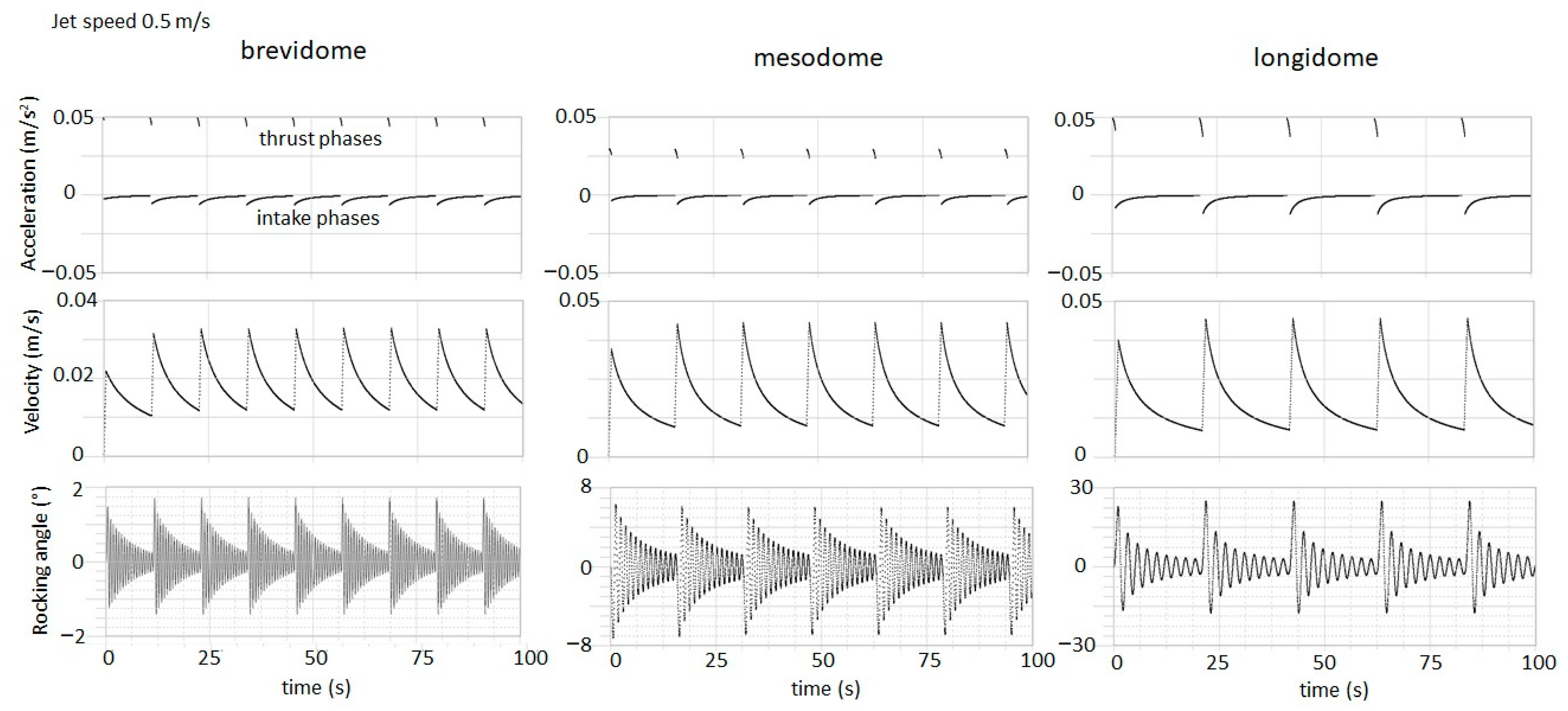
Figure 3.
Stability analysis for the three models of brevidome, mesodome, and longidome ammonoids. The analysis is presented in terms of the time average of the deviation of the rocking angle from the equilibrium as a function of the dimensionless thrust period where is the characteristic period of oscillation. This kind of arrangement shows the presence of resonances. The result depends little on the drag coefficient (see Figure S2 of Supplementary Materials).

Table 1.
Salient parameters calculated for the three models of ammonoids used as input for the computation of the ammonoid swimming. The density of the nacreous shell is 2.65
Table 1.
Salient parameters calculated for the three models of ammonoids used as input for the computation of the ammonoid swimming. The density of the nacreous shell is 2.65
| Type | Angle of Body Length (°) | Umbilical Radius (cm) | Mass of Soft Parts (g) | Mass of Shell (g) | |||||
|---|---|---|---|---|---|---|---|---|---|
| brevi | 116 | 6.48 | 5.53 | 1.100 | 19.15 | 36.60 | 46.30 | 80.6 | |
| meso | 200 | 6.89 | 6.76 | 0.493 | −27.96 | 50.76 | 19.89 | 71.1 | |
| longi | 380 | 6.33 | 5.95 | 0.112 | 30.01 | 67.21 | 16.48 | 79.9 |
Table 2.
Salient fluid-dynamical parameters are used as input for the computation of the ammonoid swimming. Jet pulse durations are close to 1 s for every examined case (to be precise, it is 0.97 s, 0.85 s, and 0.96 s for the brevidome, mesodome, and longidome models, respectively).
Table 2.
Salient fluid-dynamical parameters are used as input for the computation of the ammonoid swimming. Jet pulse durations are close to 1 s for every examined case (to be precise, it is 0.97 s, 0.85 s, and 0.96 s for the brevidome, mesodome, and longidome models, respectively).
| Name | Drag Coefficient, Frontal | Drag Coefficient, Skin Friction | Drag Coefficient, Rotational | Added Mass Coefficient | Jet Speed (cm/s) | Fraction of the Maximum Water Volume Storable in the Mantle Cavity | |
|---|---|---|---|---|---|---|---|
| Symbol | |||||||
| Value | 0.5 | 0.016 | 0.016 | 0.5 | 50 | 0.25 | 0.15 |
Table 3.
Some of the salient results from the model.
| Type | Maximum Rocking Angle (°) | Period of Oscillation (s) | Hydrostatic Qualitative Assessment | |
|---|---|---|---|---|
| brevi | 3.3 | 1.75 | 0.58 | stable |
| meso | 4.3 | 6.20 | 1.22 | intermediate |
| longi | 4.6 | 22.60 | 2.27 | unstable |
Disclaimer/Publisher’s Note: The statements, opinions and data contained in all publications are solely those of the individual author(s) and contributor(s) and not of MDPI and/or the editor(s). MDPI and/or the editor(s) disclaim responsibility for any injury to people or property resulting from any ideas, methods, instructions or products referred to in the content. |
© 2023 by the author. Licensee MDPI, Basel, Switzerland. This article is an open access article distributed under the terms and conditions of the Creative Commons Attribution (CC BY) license (https://creativecommons.org/licenses/by/4.0/).
Share and Cite
MDPI and ACS Style
De Blasio, F.V. The Hydrodynamics of Ammonoid Swimming: Equations of Motion and Rocking Resonances. Foss. Stud. 2023, 1, 34-46. https://doi.org/10.3390/fossils1010004
AMA Style
De Blasio FV. The Hydrodynamics of Ammonoid Swimming: Equations of Motion and Rocking Resonances. Fossil Studies. 2023; 1(1):34-46. https://doi.org/10.3390/fossils1010004
Chicago/Turabian StyleDe Blasio, Fabio Vittorio. 2023. "The Hydrodynamics of Ammonoid Swimming: Equations of Motion and Rocking Resonances" Fossil Studies 1, no. 1: 34-46. https://doi.org/10.3390/fossils1010004