Abstract
Wind tunnel testing of small-scale models is one of the most useful techniques to predict the performance of real-scale applications. In this work, the aerodynamic design and the construction of a small-scale model of a straight-bladed vertical axis wind turbine for wind tunnel testing has been performed. Using a double multiple streamtube model (DMST), different solidity values for the turbine and different airfoil geometries were compared to select the final design. Once an optimal design was selected, a numerical simulation using Computational Fluid Dynamics (CFD) was performed in order to obtain a more precise description of the flow field as well as the performance of the model. Future work will comprise the characterization of the model and the comparison of the experimental and numerical results.
1. Introduction
The development of renewable energy sources is a major concern in many countries. In this context, vertical axis wind turbines (VAWT) represent a feasible solution for in situ clean energy generation in urban areas, being able to produce electricity from lower wind speeds than horizontal axis wind turbines (HAWT). Another advantage of VAWTs over HAWTs is that they do not require constant reorientation to keep according to the wind flow direction. On the other hand, the main drawback of VAWTs is their difficulty to self-start for low wind velocities [1], as a result of the continuously changing incidence angle between the wind flow and the blade airfoil.
Wind tunnel testing of small-scale models is one of the most useful techniques to predict the performance of real-scale applications. In this work, the aerodynamic design and the construction of a small-scale model of a straight-bladed vertical axis wind turbine for wind tunnel testing has been performed.
2. Experimental Facility
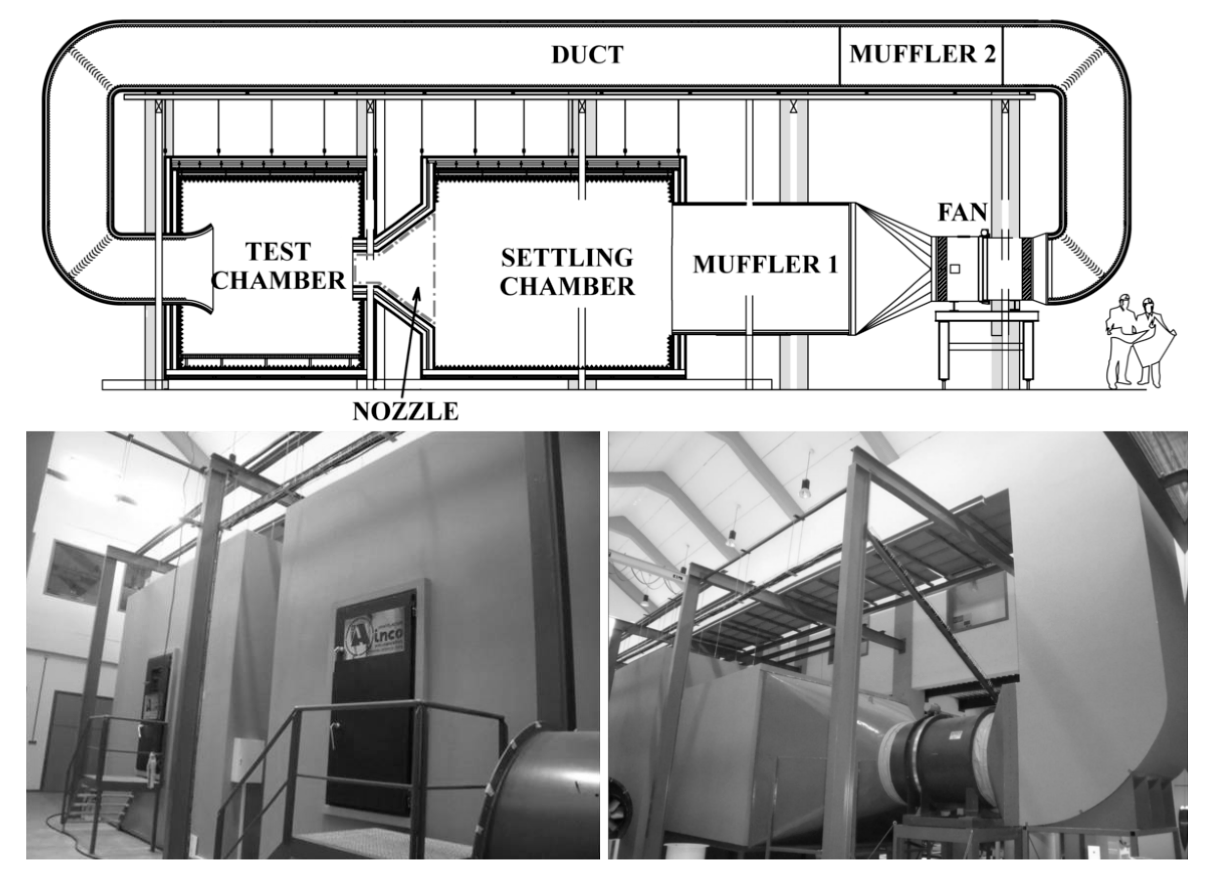
The wind tunnel to be employed for the characterization of the model is a closed-loop, open jet wind tunnel, comprising a test chamber 4.2 m long with a cross-sectional area of 4.45 × 2.80 m2 (width × height). The nozzle discharge section is 1.15 × 1 m2. The scheme of the wind tunnel is shown in Figure 1. Following the recommendations for wind tunnel blockage values from NASA [2], the maximum dimensions of the prototype to reduce blockage were calculated to be 0.8 m × 0.6 m (width × height). Thus, the diameter of the small-scale rotor was chosen to be D = 0.8 m and the blade span was chosen as H = 0.6 m, the maximum possible size to capture as much energy from the wind as possible. The wind tunnel is also suited to perform acoustic measurements.
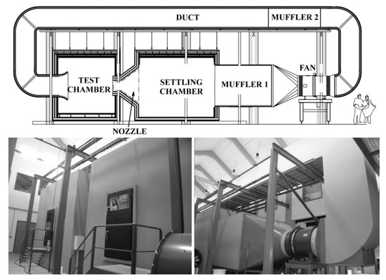
Figure 1.
Wind tunnel to be employed for the tests.
3. Aerodynamic Design of the Model
In order to select an appropriate airfoil for the blades, the methodology explained in [3] was applied. Using a double multiple streamtube model (DMST), different solidity values for the turbine and different airfoil geometries were compared to select the final design. This model combines momentum and blade element theories to evaluate the performance of the turbine in a very short lapse of time compared to Computational Fluid Dynamics (CFD) simulations. The details of the discretization and calculation scheme of the model, as well as its validation, may be found in [3].
An optimal solidity of σ = 1/3, based on the criteria of maximum energy yield and relatively low rotational speeds at operation, and the DU-06-W-200 airfoil were selected for the turbine model. This airfoil, developed in the TU Delft [4], is supposed to possess self-starting capabilities. With these values, an airfoil chord of c = 44.4 mm resulted for a three-bladed rotor. The final geometric characteristics of the VAWT model are collected in Table 1.

Table 1.
Geometrical characteristics of the VAWT model.
4. Numerical Simulation of the Performance of the Model
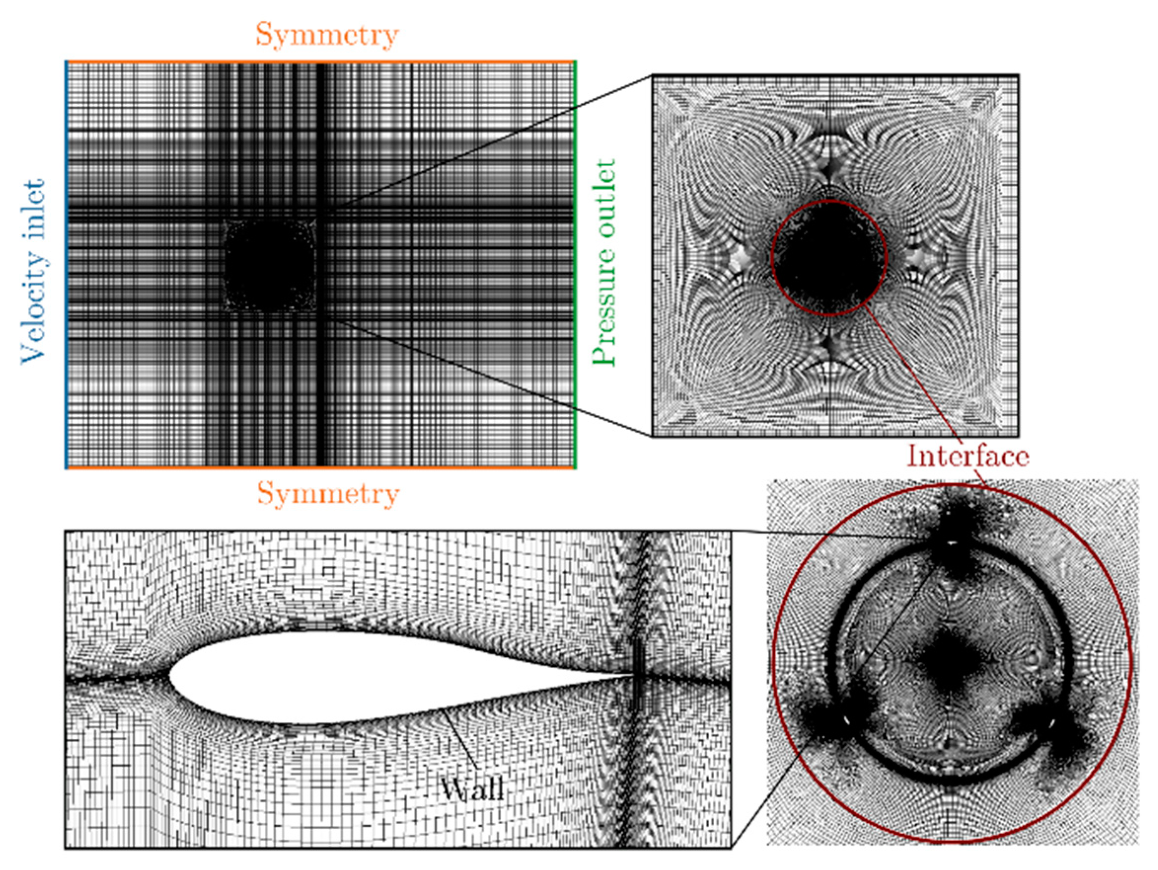
Once an optimal design was selected, a numerical simulation using Computational Fluid Dynamics (CFD) was performed in order to obtain a more precise description of the flow field as well as the performance of the model. Figure 2 shows the simulation domain, mesh and boundary conditions applied. The mesh was generated using the software GAMBIT®.
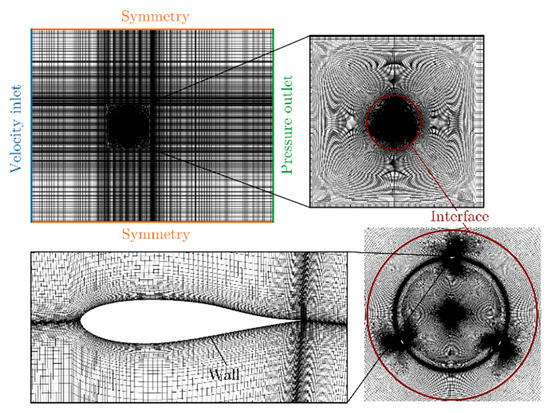
Figure 2.
Simulation domain, mesh and boundary conditions.
The Navier-Stokes equations that describe the fluid dynamics were solved with ANSYS FLUENT®, using the k-ω-SST model for the turbulence closure. A velocity-inlet condition of 10 m/s was imposed at the domain inlet, and a pressure-outlet condition equal to atmospheric pressure was applied at the domain exit. Symmetry conditions have been applied to the lateral limits of the domain, and the wall boundary condition has been applied to the blades. Finally, an interface zone separates the rotor moving zone from the rest of the domain.
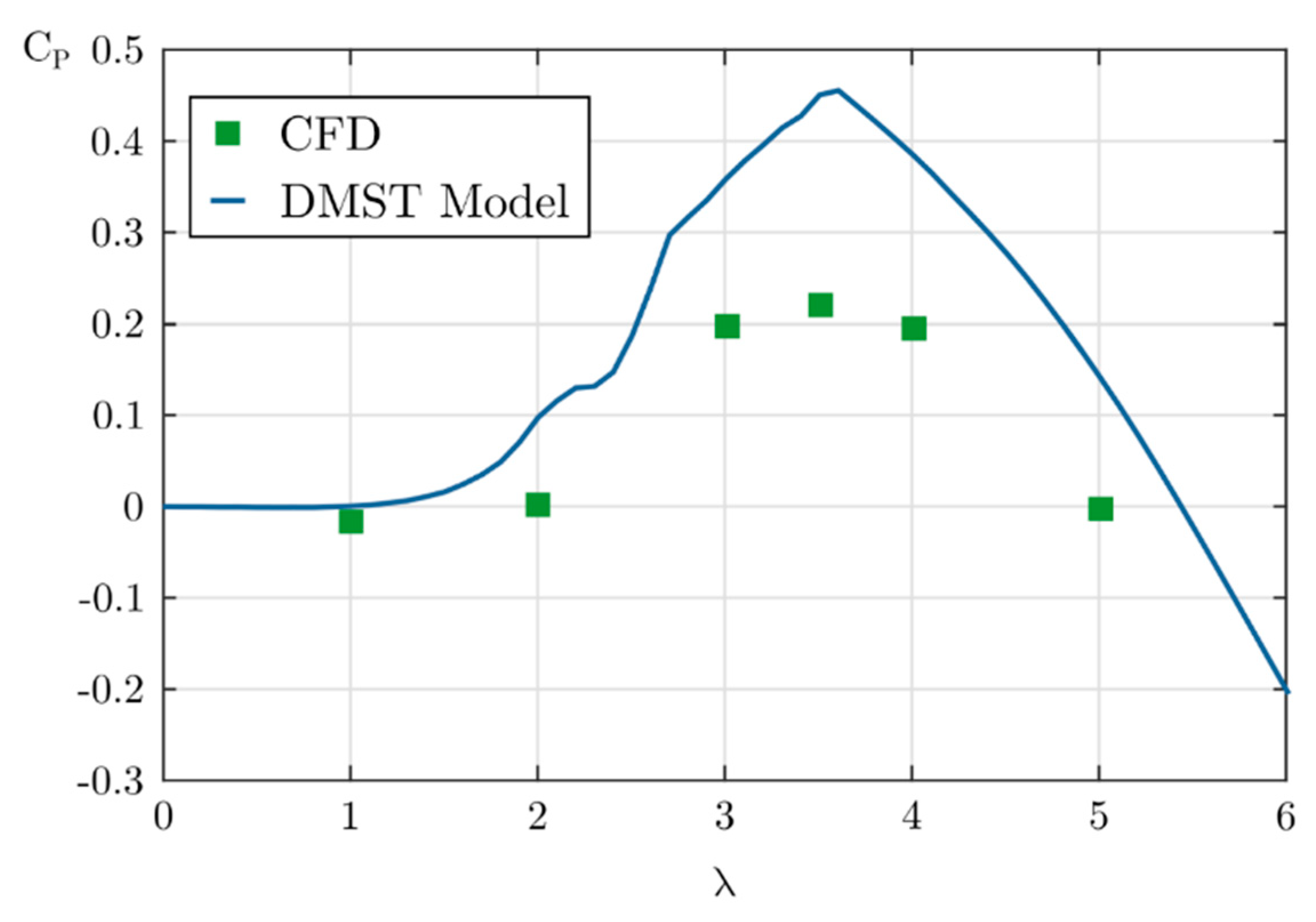
Figure 3 shows the power curve of the proposed design, predicted by both the streamtube model and the CFD simulations. Both predict the maximum performance of the turbine at the same tip speed ratio value of 3.5 (this is the relationship between the rotational velocity of the blades and the incoming wind velocity). However, there are some differences between the values of the expected power coefficients. These may be attributed to the effect of the wakes shed on the upwind part of the turbine on the downwind blades as well as to the assumptions performed by the streamtube model about the flow behavior. These aspects are to be confirmed after the experimental characterization of the model.
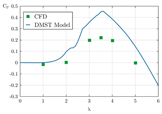
Figure 3.
Predicted power curve with the DMST model and CFD simulation.
5. Construction of the Prototype
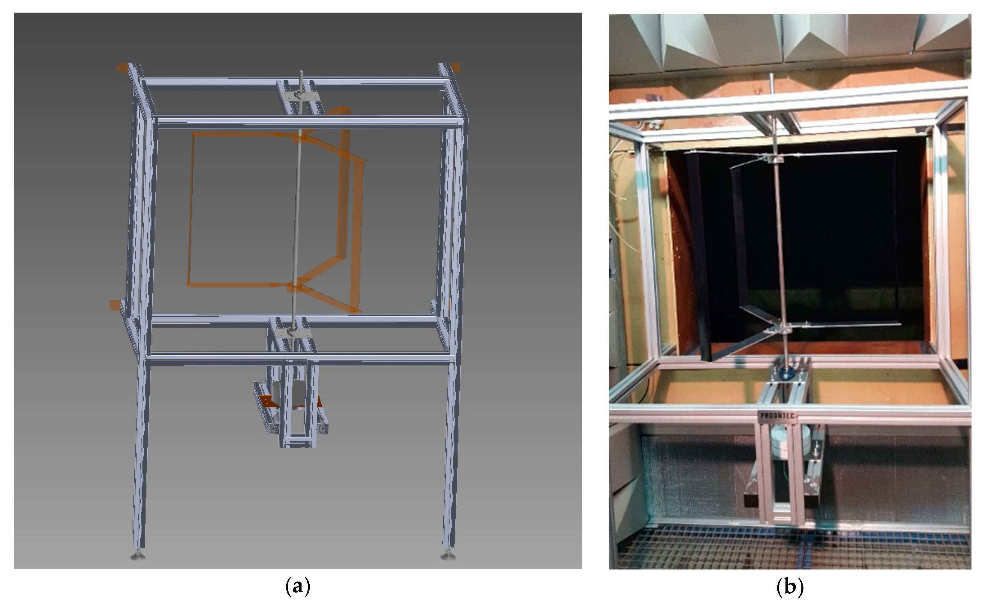
The blades were fabricated with polyamide via Selective Laser Sintering (SLS). An aluminum shaft of 15 mm diameter was employed, and support arms were specifically design to join the blades to the turbine shaft. Finally, a support structure was built with aluminum profiles to hold the turbine at the correct position. Figure 4 shows the design of the rotor alongside the support structure and the final mounting in the wind tunnel test chamber.
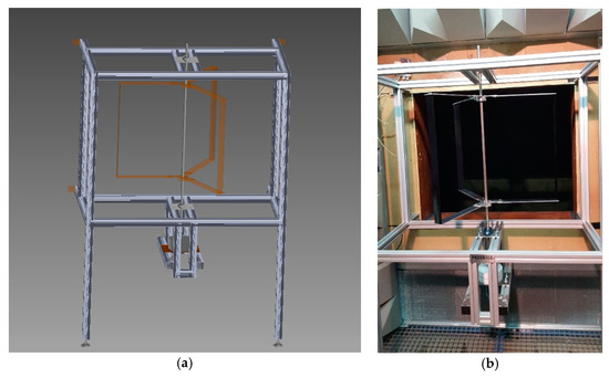
Figure 4.
Final prototype design: (a) CAD view; (b) Assembly and placing into the wind tunnel.
6. Conclusions
The aerodynamic design and construction of a small-scale model of a straight-bladed vertical axis wind turbine has been performed using both streamtube models and CFD simulations. Streamtube models are able to compare quickly between different designs, whereas CFD simulations, at the expense of higher computational times, yield a more accurate prediction of the performance of a particular design. Future work will comprise the characterization of the model and the comparison of the experimental and numerical results.
Author Contributions
All the authors contributed substantially to this work: the design of the model using the streamtube model, the computational fluid dynamics simulations of the proposed design, the analysis of the results and the mechanical design and construction of the prototype. A.M.-F. collected all the results and wrote the paper.
Acknowledgments
This work has been supported by the “FPU” predoctoral research scholarship provided by the Spanish Ministry of Education, Culture and Sports. The authors also want to acknowledge the support from the Projects “Prototipo experimental para la contrastación de modelos de predicción de prestaciones de turbinas eólicas de eje vertical (VAWT)” (SV-18-GIJON-1-05) from the University Institute of Industrial Technology of Asturias, financed by the City Council of Gijon, Spain, “Diseño optimizado de una turbina eólica de eje vertical” from the University of Oviedo Foundation, financed by the company AST Ingeniería and “Desarrollo y construcción de turbinas eólicas de eje vertical para entornos urbanos” (ENE2017-89965-P) from the Spanish Ministry of Economy, Industry and Competitiveness.
Conflicts of Interest
The authors declare no conflict of interest. The founding sponsors had no role in the design of the study; in the collection, analyses, or interpretation of data; in the writing of the manuscript, and in the decision to publish the results.
References
- Hill, N.; Dominy, R.; Ingram, G.; Dominy, J. Darrieus turbines: The physics of self-starting. Proc. Inst. Mech. Eng. A J. Power Energy 2009, 223, 21–29. [Google Scholar] [CrossRef]
- Daugherty, J.C. NASA AMES Unitary Plan Wind Tunnel Blockage Recommendation; NASA Ames: California, USA, 1984. [Google Scholar]
- Meana-Fernández, A.; Solís-Gallego, I.; Oro, J.M.F.; Díaz, K.M.A.; Velarde-Suárez, S. Parametrical evaluation of the aerodynamic performance of vertical axis wind turbines for the proposal of optimized designs. Energy 2018, 147, 504–517. [Google Scholar] [CrossRef]
- Claessens, M.C. The Design and Testing of Airfoils for Application in Small Vertical Axis Wind Turbines. Master’s Thesis, TU Delft, Delft, The Netherlands, 2006. [Google Scholar]
Publisher’s Note: MDPI stays neutral with regard to jurisdictional claims in published maps and institutional affiliations. |
© 2018 by the authors. Licensee MDPI, Basel, Switzerland. This article is an open access article distributed under the terms and conditions of the Creative Commons Attribution (CC BY) license (https://creativecommons.org/licenses/by/4.0/).

