Article

Adaptive Single Neuron Anti-Windup PID Controller Based on the Extended Kalman Filter Algorithm

by
Jesus Hernandez-Barragan
,
Jorge D. Rios
,
Alma Y. Alanis
,
Carlos Lopez-Franco
,
Javier Gomez-Avila
and
Nancy Arana-Daniel
*
Centro Universitario de Ciencias Exactas e Ingenierías, Universidad de Guadalajara, Blvd. Marcelino García Barragán 1421, Guadalajara C.P. 44430, Jalisco, Mexico
*
Author to whom correspondence should be addressed.
Electronics 2020, 9(4), 636; https://doi.org/10.3390/electronics9040636 (registering DOI)
Submission received: 7 March 2020 / Revised: 6 April 2020 / Accepted: 7 April 2020 / Published: 11 April 2020

Abstract

:
In this paper, an adaptive single neuron Proportional–Integral–Derivative (PID) controller based on the extended Kalman filter (EKF) training algorithm is proposed. The use of EKF training allows online training with faster learning and convergence speeds than backpropagation training method. Moreover, the propose adaptive PID approach includes a back-calculation anti-windup scheme to deal with windup effects, which is a common problem in PID controllers. The performance of the proposed approach is shown by presenting both simulation and experimental tests, giving results that are comparable to similar and more complex implementations. Tests are performed for a four wheeled omnidirectional mobile robot. Tests show the superiority of the proposed adaptive PID controller over the conventional PID and other adaptive neural PID approaches. Experimental tests are performed on a KUKA® Youbot® omnidirectional platform.

1. Introduction

Presently, Proportional–Integral–Derivative (PID) controllers are still among the most popular controllers used in the industry [1,2,3]. However, a PID is just adequate for a nominal process; it performs poorly for a system with uncertainties in operating conditions or environmental parameters [2,4,5]. It is well known that if the mathematical model of a plant is available, various techniques to determine PID controller parameters exist. Based on that, improvements and tuning mechanisms were proposed in the literature for conventional PID controllers. However, those techniques are mainly offline methodologies, and in most cases, they require a model of the system, which is commonly not available [1,2,3]. Among these techniques, adaptive neural PID controllers are presented as an option due to neural networks characteristic that allows them to adapt themselves to changes in operating conditions and environmental parameters, giving the controller the capability of adapting its parameters online [5,6,7]. Adaptive control techniques are important to solve problems in robotics research, such as control of robot manipulators [8,9], control of mobile robots [10,11] and formation control [12], control of underwater vehicles [13,14], control for teleoperation systems [15] and industrial applications [16,17].
Adaptive neural PID controllers have been presented mainly in three different forms:
  • Single neuron PID controllers
    Examples of this group are works [6,18,19,20,21].
    These adaptive controllers are base on a single neuron whose inputs are the proportional error (P), integral of the error (I), and derivative of the error (D) (see Figure 1).
  • Multi-layer neural PID controllers
    Examples of this group are works [4,22,23,24,25,26].
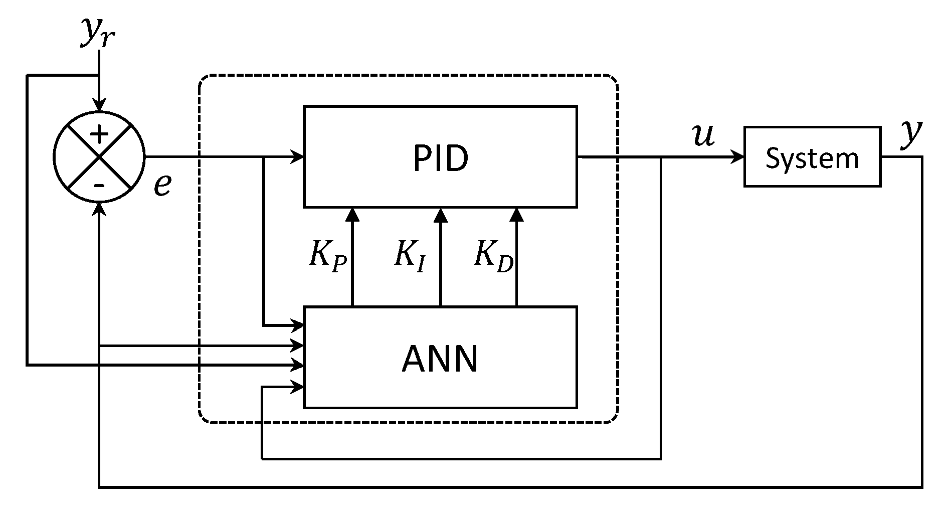
    These works are mainly based on an architecture as shown in Figure 2, where the output layer only has one neuron, and the immediately before layer to this output layer has three neurons, each one dedicated to the proportional gain ( K P ), the integral gain ( K I ), and the derivative gain ( K D ), respectively. The inputs are the proportional error (P), integral of the error (I), and derivative of the error (D). In some works, the inputs include the system output and its reference.
  • Hybrid neural PID controllers
    Examples of this group are [5,27,28].
    These adaptive neural PID controllers are based on improving the performance of a conventional PID controller (Figure 3). Typically, the neural network chooses online the proportional gain ( K P ), the integral gain ( K I ), and the derivative gain ( K D ) parameters of the controller. However, they tend to have slow learning rates, complex architectures, and high computational cost [4,23].
Training methods for the previous mentioned adaptive neural PID controllers are mostly based on backpropagation. Also, most of them only report simulation results using benchmark systems that do not necessarily represent real-world problems. Another common problem with PID controllers is the windup effect [29]. The windup effect occurs when the cumulative error in the integral control action produces a saturation on the actuators, which while on the saturation zone, the system loses controllability [30,31]. The windup effect contributes to poor performance, overshoot, high settling time, and instability [32,33]. Anti-windup methods were proposed to deal with these issues, among them, the limiter integrator, conditional integration, back-calculation, the observer approach, modified tracking anti-windup, and others [31,33]. The inclusion of anti-windup strategies in control designs is essential to be considered. The previously mentioned adaptive neural PID controllers do not include it.
This work proposes an adaptive single neuron PID controller trained with the Extended Kalman Filter (EKF) training algorithm. The EKF for neural networks were proven to have faster learning speeds and convergence times than training based on backpropagation, which make them ideal for experimental and real-time tests [34,35]. Moreover, the neuron PID controller includes a back-calculation scheme to deal with windup effects. The proposed anti-windup scheme uses the information of the cumulative error and the input saturation to compute the integral action dynamically. No special tuning is required to adjust the contribution of input saturation, which is needed by conventional back-calculation methods. The performance of the proposed controller is shown through simulation and experimental results using an omnidirectional robot. For simulation tests, the robot is simulated on Matlab® (Matlab is a registered trademark of the MathWorks, Inc.), on the other hand, for the experimental case a KUKA® (KUKA is a registered trademark of KUKA Aktiengesellschaft Germany) Youbot® (Youbot is a registered trademark of KUKA Aktiengesellschaft Germany) is used. Moreover, comparative results are presented with respect to the conventional PID controller, an adaptive single neuron PID controller, and an adaptive multilayer PID controller. A case of study is also presented to compare the performance of a PID controller with an anti-windup method against the proposed adaptive controller. The control objective is set as trajectory tracking, where through the tests and a smaller tracking error is obtained with the proposed controller compared to the other implemented techniques. Since the proposal is based on a neuron and an the EKF training algorithm, then, it is essential to mention the works (Sento, 2016, [24] and Gomez, 2016, [26]) where multilayer PID controllers are presented. However, those works only present simulation results; the first one uses an inverted pendulum system and a DC motor system. The second one presents results using a quadrotor system and a control scheme that presents a neural PD controller. Moreover, both approaches do not include an anti-windup scheme.
The main contribution of this work is an adaptive single neuron PID controller trained with an extended Kalman filter training algorithm, which includes an anti-windup scheme to overcome the overshoot and settling time inconveniences. The proposed controller scheme offers excellent results compared with other similar proposals and also compared to more complex ones.
A mobile system is considered to be autonomous if its motion is based on its own knowledge of the environment. Mobile robots can make decisions and perform appropriate actions without the intervention of a human user. To perform an autonomous motion, control techniques are required. The use of controllers that require the tuning of gains is not appropriated because the intervention of a user is needed every time the model changes. However, the proposed adaptive neuron controller provides an auto-tuning mechanism that contributes to robot autonomy.
Path planning is an important task to be solved for autonomous robot systems. Path planning consists of the determination of a path from an initial point to an endpoint, without collision with obstacles in the environment. Moreover, the autonomous guided vehicle (AGV) robots are widely used to transport materials between assembly stations. The AGV robots need to use a controller technique to follow special paths, which are usually electrical guide wires based on sensors. A trajectory tracking control algorithm is crucial to follow the given paths successfully. The proposed approach proved to be robust and reliable for control tracking tasks that are beneficial for autonomous mobile systems.
The work outline is as follows:
  • in Section 2 the proposed adaptive neuron anti-windup PID controller is presented, where EKF neural PID controller is presented, where Section 2.1 explains the EKF training algorithm.
  • Section 3 presents the implementation of the propose adaptive controller for position tracking of an omnidirectional mobile robot. In Section 3.1 the robot kinematics are presented for illustrative purposes, Section 3.2 presents the conventional PID controller implementation scheme, and Section 3.3 presents the adaptive control scheme.
  • in Section 4, both simulation (Section 4.1) and experimental results (Section 4.3) are presented, showing the performance of the proposed single neuron PID controller against the conventional PID and others neural PID controllers.
  • in Section 5, important conclusions are presented and discussed.

2. Adaptive Single Neuron PID Controller Based on the Extended Kalman Filter Algorithm

An artificial neuron is a mathematical simplification of a biological neuron; however, simple as it is, an artificial neuron is capable of accomplishing multiple tasks. Many artificial neurons can then be put together to achieve even more complex tasks [7]. Similar to a neuron and a neural network, they learn a task of function obtaining information of the environment, such knowledge or information is stored in the synaptic weights ω , the output of a neuron is computed as represented in Equation (1)
y ^ = ϕ ( ω x )
where ω is a weight vector, x the input vector, y ^ is the output of the neuron, and ϕ is an activation function. Training can be perform using different paradigms please see [7,36].
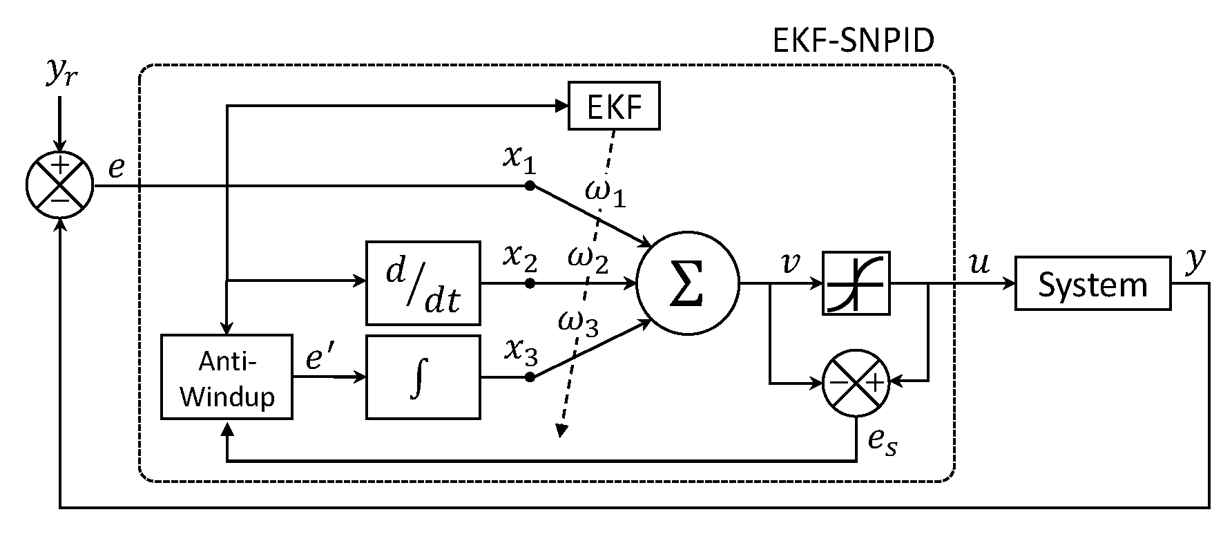
The proposed adaptive single neuron PID controller is illustrated in Figure 4, where e is the error (2) of the system under consideration, this error is the difference between the reference ( y r ) and the system output (y). The error e is the output of the anti-windup scheme (8). x 1 , x 2 , and x 3 are the inputs to the neuron and they are define as the proportional error (3), the integral of the error (5), and the derivative of the error (4) [37]. The weights ω 1 , ω 2 , and ω 3 , are adapted online using the extended Kalman filter algorithm described in Section 2.1, and they represent the K P , K I , and K D gains, respectively. v is the weighted sum (6), u is the output of the neuron (7), where as activation function tanh ( · ) is selected and α scales the amplitude of tanh.
e k = y r k y k
x 1 k = e k
x 2 k = e k e k 1
x 3 k = j = 1 k e k
v k = i = 1 3 ω i k x i k
u k = α tanh v k
the activation function tanh ( · ) reacts in the range [ 1 , 1 ] . Moreover, the parameter α needs to be selected depend on the control action requires for control tasks.
In the presence of actuator saturation, the cumulative error in the integral action produces windup effects. Back-calculation methods are often used to overcome these inconveniences. In general, back-calculation methods consist of reducing the integral action by feeding back the difference between saturated and unsaturated control signals. In order to prevent the windup effects, the feed-back difference e s is computed (9). The error e s defines the differences between the outputs u and v, and it is only considered when the value of v exceeds the saturated control signal u scaled by the parameter α , see (7). The anti-windup scheme consists of computing the error e , which handle the integral action. This scheme is defined as
e k = e k + e s k if | v k | > α e k otherwise
where
e s k = u k v k
The anti-windup scheme is conducted as follows: when the control signal u is saturated, then the error e is considered to be the actual error e plus the feed-back difference e s to reduce the cumulative error. When the control signal u is not saturated, the error e is the same as the error e. In this case, the cumulative error is not reduced. Typically, limitations in actuators provoke saturation. However, the presented anti-windup scheme prevents the actuator saturation by the selection of α .
It is important to remark that most of the reported adaptive neural PID controllers present training strategies mainly based on the backpropagation algorithm. In this work, the proposed adaptive neuron is trained online using an Extended Kalman Filter (EKF) algorithm that is described in the next section. An important advantage of online training is that the network can adapt itself to changes in the nature of the problem under consideration.

2.1. Adaptive Neuron Training Based on the EKF Algorithm

Several algorithms were reported for the training of neural networks, most of them with the problem of having a slow learning rate and high sensitivity to initial conditions. On the other hand, algorithms based on the Kalman filter are an alternative [34,38], as they reduce the number of neurons and epochs. Moreover, they improve learning convergence [39], and they proved to be reliable for online and offline training for several applications for both feedforward and recurrent neural networks [34,38,40,41,42]. The Kalman filter is used to estimate the state of a linear system with additive white noise, both in the state and in the output using a recursive solution, which uses previous state and the current input [34]. In the case of neural networks, due to the nonlinear mapping EKF is required, and the weights of the neural network become the state variables to be estimated. The error between the measured output and the network output is considered additive white noise. The training goal is to find an optimal weight vector that minimizes the prediction error [34,38]. The EKF is used due to the mapping of the neural network is nonlinear [34,38,43]. The idea behind the use of the EKF to train the ANN is that other training algorithms, such as gradient descent, recursive least squares and backpropagation, are particular cases of the Kalman filter; for this reason, the EKF is suitable for training [44,45]. Moreover, Neural networks trained with the EKF demonstrated faster learning speeds and convergence times than networks trained with algorithms based on backpropagation [34,43].
The training algorithm for the proposed scheme is an EKF algorithm as proposed in [38], which was proven to be reliable for many applications using multilayer and recurrent neural networks [35,38,41]. Control scheme of the training is depicted in Figure 5. The training of this neuron is performed by an online supervised scheme in which the desired response is the desired trajectory, this is the reason such an error is the one considered for the training, which is going to train the neuron to give control signal such as the trajectory error is minimized.
The EKF training algorithm is given by Equations (10)– (12) [43].
K k = P k H k R k + H k P k H k 1
ω k + 1 = ω k + η K k e k
P k + 1 = P k K k H k P k + Q k
H j k = u k ω j k = u k v k v k ω j k = α sech 2 v k x j k
where ω R 3 is the weight vector, K R 3 × 1 is the Kalman gain vector, P R 3 × 3 , Q R 3 × 3 , and R R 1 × 1 are covariance matrices of weight estimation error, estimation noise, and error noise, respectively. η R is the Kalman filter learning rate, and H R 3 × 1 is a matrix whose entries H j are the derivative of the neural network output with respect to each weight Equation (13), u R is the neuron output, the error e R is defined as the difference between the desired output and the neuron output (2) [43].
The training objective is to have a set of weight ω such as the signal u minimizes the error between the desired reference and the system output in (2). In the EKF algorithm, the learning rate η is a scalar. However, it is proposed to use η R 3 × 1 to provide a learning rate to adjust each weight ω i independently with η i , respectively. Finally, the proposed neuron PID controller trained with the Extended Kalman Filter algorithm is called EKF-SNPID. A brief description of the proposed approach is given in the flowchart of Figure 6.

3. Implementation of the Adaptive Neuron PID Controller for an Omnidirectional Mobile Robot

Omnidirectional mobile robots were used in many robotic applications due to their movement capabilities, which allow them simultaneously to move towards any position and reach any desired orientation [46,47,48,49]. In contrast to the limit movement capabilities of a conventional mobile robot with two or four wheels due to their nonholonomic kinematics constraints [50]. In this work, the proposed single neuron PID controller is to make an omnidirectional mobile robot reach a desired position and orientation; for this case, the control computes velocities.

3.1. Omnidirectional Mobile Robot Kinematics

The considered omnidirectional mobile robot in this work is made up of four mecanum wheels placed similarly to a conventional vehicle (Figure 7). The pose of the robot with respect to the world frame is given by three degrees of freedom (DOF), which are the positions x, and y, and the orientation θ . Velocities of the mobile robot in the base frame are given by v x , v y , and v θ . Velocity v i correspond to the velocity of each wheels with i = 1.2.3.4 , where v i = r i × w i , where r i is the radius of the wheels, and w i is angular velocity. The parameter L is half of the distance between the front and the rear wheels, and l is half of the distance between the left and right wheels.
The inverse kinematics of the omnidirectional mobile robot in the base frame are given by (14) [51].
v 1 t v 2 t v 3 t v 4 t = 1 1 L + l 1 1 L + l 1 1 L + l 1 1 L + l v x t v y t v θ t
Velocities v x v y v θ are mapped into the velocities x ˙ y ˙ θ ˙ of the world frame using the transformation (15).
x ˙ t y ˙ t θ ˙ t = cos θ t sin θ t 0 sin θ t cos θ t 0 0 0 1 v x t v y t v θ t
Equation (16) is obtained from Equations (14) and (15).
v 1 t v 2 t v 3 t v 4 t = 2 sin θ + π 4 2 cos θ + π 4 L + l 2 cos θ + π 4 2 sin θ + π 4 L + l 2 cos θ + π 4 2 sin θ + π 4 L + l 2 sin θ + π 4 2 cos θ + π 4 L + l x ˙ t y ˙ t θ ˙ t = J θ t x ˙ t y ˙ t θ ˙ t
where J θ is a transformation matrix, which maps the mobile robot velocities x ˙ y ˙ θ ˙ into the velocities for each of the wheels.
For further information about the kinematics of the considered mecanum omnidirectional mobile robot, please go to references [52,53].

3.2. Conventional Velocity Control Design

To achieve the position tracking, proper velocities have to be computed, then, the controller has to find velocities u x k , u y k , and u θ k at step time k, to drive the mobile robot, from the current pose (17) to the desired pose (18). The error between the desired pose and current pose is defined as (19):
x k y k θ k
x r k y r k θ r k
x e k y e k θ e k = x r k x k y r k y k θ r k θ k
A PID control can be use to compute the velocities v i k of the mobile robot in order to asymptotically stabilize the system, for i = 1, 2, 3, 4 [51]. A discrete PID control laws [37] at step k are given in Equations (20)–(22), respectively. For this control scheme, there is one PID module for each error x e k , y e k , and θ e k . Parameters K P x , K I x and K D x are the proportional, integrative and derivative gains for error x e , respectively. Similarly, the parameters K P y , K I y and K D y are the gains for error y e , and K P θ , K I θ and K D θ are the gains for error θ e .
u x k = K P x x e k + K I x j = 1 k x e j + K D x x e k x e k 1
u y k = K P y y e k + K I y j = 1 k y e j + K D y y e k y e k 1
u θ k = K P θ θ e k + K I θ j = 1 k θ e j + K D θ θ e k θ e k 1
Based on (16), the control outputs u x k , u y k and u θ k are mapped to each wheel control velocity u j k with j = 1.2.3.4 , using transformation matrix J θ k as follows
u 1 k u 2 k u 3 k u 4 k = J θ k u x k u y k u θ k
The conventional PID is widely used to control mobile robots due to its simplicity and performance [51,54,55,56]. It is well known that the main problem of the conventional PID is the manual tuning of the proportional, integrative, and derivative gains. However, this paper presents an adaptive single neuron PID approach to overcome this inconvenience. The proposed approach can adjust itself online during the operation of the system.

3.3. Control Scheme Using the Adaptive Single Neuron PID Controller

The proposed control scheme based on the adaptive single neuron PID controller trained with EKF algorithm (EKF-SNPID) of an omnidirectional mobile robot is shown in Figure 8. In order to minimize the errors x e , y e and θ e , an adaptive PID controller module is designed for each DOF. Then, each output control signal (24) corresponding to each single neuron PID control module which is mapped into the control velocities signals (25) for each wheel, respectively. The system output is given by the pose of the mobile robot (26).
u x k u y k u θ k
u 1 k u 2 k u 3 k u 4 k
x k y k θ k
It is important to note that even with the inclusion of the anti-windup block to the single neuron architecture (25), the computed control signal is bounded, then such control signal designed for a dynamic system, such as the one for the mobile robot (15) is a feed forward neural control law, which composes a stable system [57,58,59].

4. Results

In Section 4.1 results of both simulation and experimental tests of the proposed adaptive single neuron PID controller trained with extended Kalman filter (EKF-SNPID) compared to conventional PID, backpropagation trained adaptive neural PID controller (BP-PIDNN) [4], and an adaptive neuron PID controller trained with Hebbian learning rule (HR-PIDNN) [19]. Then, in Section 4.1.1, the proposed EKF single neuron PID controller is compared with a conventional PID controller with a back-calculation anti-windup method [29].
The presented kinematic model of the mobile robot is given in continuous time domain. This model is not used by the proposed EKF single neuron controller scheme. For simulation tests, the kinematic model is programmed on Matlab® where it is discretize using zero-order hold Matlab® function method. For the experimental tests, the information is sent a received on discrete instants of time.

4.1. Simulation Results

For this section, it is important to clear out that in the literature, the reported adaptive neural PID controllers do not integrate an anti-windup scheme. In this way, the proposed scheme is compared against different adaptive neural PID controllers as they where reported. Moreover, limits for control signals are not set due to lose of controllability of the techniques the proposal is compared with.
Simulation experiments consist of the tracking of different trajectories. Test are implemented in Matlab®. Parameters for the omnidirectional mobile robot are set as: L = 0.2355 m, l = 0.15 m, r = 0.0475 m, and sampling time k = 0.05 s.
For conventional PID controller, proportional gains are set as: K P x = 0.3 , K P y = 0.3 and K P θ = 0.2 , integral gains K I x = 0.2 , K I y = 0.2 and K I θ = 0.1 , and derivative gains K D x = 0.1 , K D y = 0.1 and K D θ = 0.05 . In addition, for adaptive neural PID controllers, weights are initialized randomly.
Parameter setting for proposed EKF-SNPID controller are: matrices P and Q are initialized as diagonal matrices with P 11 = P 22 = P 33 = 1 and Q 11 = Q 22 = Q 33 = 0.1 , the parameter R = 0.0001 , Kalman filter learning rates η 1 = 0.1 , η 3 = 0.1 and η 2 = 0.01 and α = 0.3 . The selection of these parameters was chosen experimentally. Considered trajectories at each step time k are generated as follows:
  • a sinusoidal trajectory is computed as
    x r k = 0.05 k y r k = 0.2 sin 1 0.5 x r k π θ r k = π 8
  • a rose curve trajectory generated as
    a = 0.2 + 0.05 cos 3 0.05 k π x r k = a cos 0.05 k π y r k = a sin 0.05 k π θ r k = π 4
To compare the performance of the considered controllers, resulting tracking and control signals are shown in graphs. Additionally, the root mean square (RMS) and mean absolute deviation (MAD) measures of the obtained errors are reported.

4.1.1. Simulation Test: Sinusoidal Reference

Trajectory tracking results for the sinusoidal trajectory reference are shown in Figure 9. As with the circular trajectory case, the proposed adaptive PID controller achieves the best tracking among the other compared controllers.
Velocity control signals for the sinusoidal trajectory reference are provided in Figure 10. The proposed EKF-SNPID controller reports faster performance than the others.
The system response for the sinusoidal trajectory reference is shown in Figure 11 where Figure 11a shows the system response for x. In this case, it is shown that all compared controllers achieve the reference successfully. Respect to system response for y, the proposed adaptive PID controller outperformed the others, see Figure 11b. The proposal reported a less steady-state error. In contrast, the other controllers have bigger errors. In Figure 11c, the system response for θ is presented. In this case, there is not overshoot provided by the proposed EKF-SNPID.
The RMS and MAD results for the sinusoidal trajectory reference are presented in Table 1. The proposed adaptive neuron PID controller outperforms the other compared controllers.

4.1.2. Simulation Test: Rose Curve Reference

Figure 12 shows the trajectory following results for the rose curve trajectory. Also for this case, the proposed adaptive PID controller outperformed the other controllers.
Figure 13 provides the velocity control signal for the rose curve trajectory. Velocity control signals for EKF-SNPID are lower than the others.
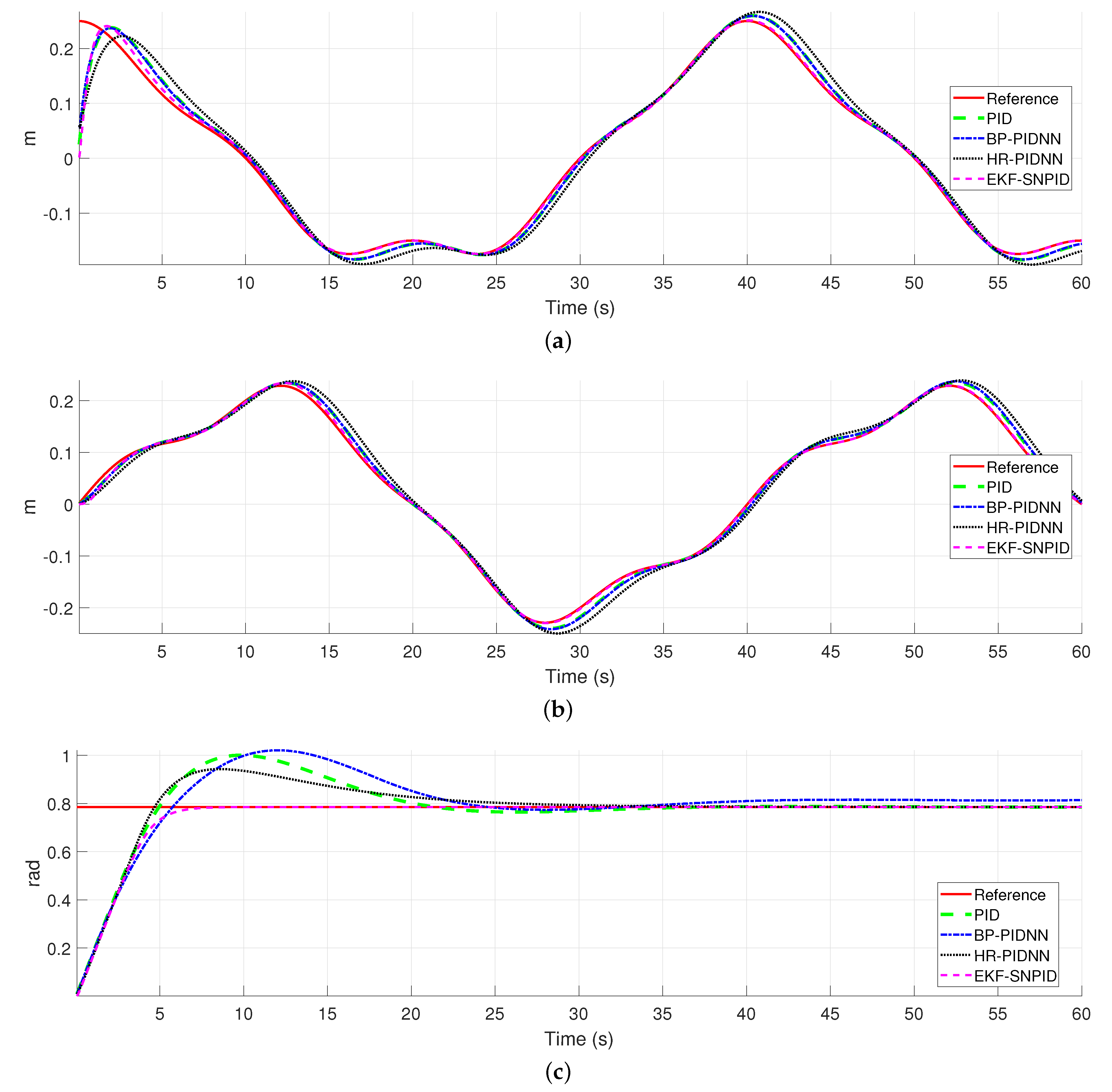
Figure 14 shows the system response for the rose curve trajectory test. The system response for x, y, and θ are shown in Figure 14. The proposed adaptive PID controller follows in a better way the desired references than the other controllers. In this case, the proposed approach has the lowest steady-state errors. Additionally, the proposed controller reported a fast system response without overshoot respect to θ , see Figure 14c.
Table 2 reports the RMS and MAD results for the rose curve trajectory. In this case, the BP-PIDNN reported the best RMS respect to the x e error. On the other hand, the proposed EKF-SNPID controller performed better than the other controllers for the y e and θ e error. Additionally, the proposal achieved the best results with the lowest MAD results.
Based on the reported results so far, the BP-PIDNN controller performed better than the conventional PID controller. However, the performance of the proposed EKF-SNPID controller is superior to the compared controllers, respect to the best transient response, the smaller steady-state errors, and lower overshoot results. Additionally, the performance of the PID controller for tracking is acceptable. However, it is necessary to adjust the PID gains manually to improve its performance. In contrast, the proposed adaptive EKF-SNPID controller does not require any adjustment.

4.2. Anti-Windup Tests

The following simulations results show the performance of the proposed neuron PID controller with the integration of the back-calculation anti-windup method. Simulations consist of the tracking of a trajectory with offsets. These offsets provoke velocity saturation in the mobile robot when trying to reach the necessary speeds to get to the trajectory. The performance of the proposed adaptive single neuron controller is compared against a PID with back-calculation anti-windup [29]. The conventional PID is also considered for simulations to contrast the windup effects. These tests are implemented in Matlab®.
The omnidirectional mobile robot of the previous simulation is also used for the following tests. Similarly, parameter settings of the considered controllers are chosen. Moreover, the back-calculation anti-windup on PID requires a parameter for the feeding back information [29], which is defined as T s , and its value is selected as 0.1 . This tuning is not required by the proposed EKF-SNPID controller.
The considered trajectory at each step time k are given as follows:
  • An approximated trapezoidal trajectory which is calculated as
    x r k = 0.1 k b = 3.0 + 0.3 sin 1 1.5 x r k π y r k = 3.2 if b 3.2 3.2 if b < 3.2 b otherwise θ r k = π 3
To compare the performance of the considered controllers in this test, results are shown in graphs. Moreover, the RMS and MAD results are presented in terms of percent error. To compare the performance of the proposed approach against the PID controller, we proposed to measure the percent error as
% error = PID R M S EKF - SNPID R M S PID R M S × 100
where a positive percent error indicates that the proposed approach performs better than PID, and a negative percent error indicates that PID overcomes the proposed approach. The same equation is used to compare the proposed controller against the PID with anti-windup. Similarly, the percent error of MAD results are also measured.

Simulation Test: Trapezoidal Reference

Trajectory tracking and Velocity control signal for the trapezoidal reference are give in Figure 15. The conventional PID presents a high tracking error caused by the windup effects, see Figure 15a. The Figure 15c shows that the PID with anti-windup reports better tracking results, but the tracking response is slow compared to the proposed EKF-SNPID with anti-windup that shows the fastest tracking response without windup effects, see Figure 15e. The Figure 15b,d,f reports that the saturation limits are reached by all controllers. The control signals are saturated at u x = 0.3 m/s, u y = 0.3 m/s and u x = 0.3 rad/s.
The Figure 16 reports the system response for the trapezoidal trajectory tracking. The conventional PID reports the highest overshoot. The PID reduces the overshoot with anti-windup. Moreover, the proposed EKF-SNPID suppressed the overshoot and it reaches the reference faster than the others.
The percent errors for this test are give in Figure 17. As can be seen, a percent error is shown for each error of the mobile robot pose x e , y e and θ e . A percent error for RMS and MAD results is also computed. Figure 17a reports the comparison of the proposed EKF-SNPID against the conventional PID and Figure 17b illustrates the of EKF-SNPID against the PID with anti-windup. The reported results for both comparison are positive percent errors. This indicates that the proposed adaptive EKF-SNPID performs betters than the compared controllers.
This test indicates that the conventional PID controller suffers from overshot, which is provoked by saturation velocity. The use of the back-calculation method in the PID highly reduces this inconvenience. However, its response time and tracking results are poor. The conventional back-calculation requires the tune of a gain parameter to improve this performance. In contrast, the proposed EKF-SNPID with anti-windup outperformed the conventional PID and the PID with anti-windup. The proposal reduces overshoot effectively. Moreover, it has a better response time and tracking performance, even in the presence of saturation limits. Additionally, it does not require any adjustment or tuning.

4.3. Experimental Results

Experiment tests are performed using a four-wheeled omnidirectional mobile robot. The considered omnidirectional mobile robot is a KUKA® Youbot® platform (Figure 18). Its parameters are L = 0.2355 m and l = 0.1 m, and the wheel radius r = 0.0475 m. For the experimental test, the performance of the proposed EKF-SNPID controller, which includes the back-calculation anti-windup, is compared to the PID controller with anti-windup. The PID and the proposed approach were implemented in C++ using the KUKA® Youbot® API. The sampling time for the system is set to 0.05 s.
In the case of the PID controller, proportional gains are set as K P x = 1.5 , K P y = 1.5 and K P θ = 0.5 , integral gains are set as K I x = 0.5 , K I y = 0.5 and K I θ = 0.3 , and derivative gains are set as K D x = 0.01 , K D y = 0.01 and K D θ = 0.01 . For the back-calculation method, the parameter tuning T s was selected as 0.1 .
For the proposed adaptive EKF-SNPID controller, Kalman filter settings are given below. The matrices P and Q are initialized as diagonal matrices with P 11 = P 22 = P 33 = 1 and Q 11 = Q 22 = Q 33 = 0.1 . The parameter r is set as 0.0001 . The Kalman filter learning rates are set as η 1 = 0.2 , η 3 = 0.2 and η 2 = 0.01 and α = 0.3 . Moreover, initial weights are set randomly. All these parameters were chosen experimentally.
The experiments consist of some trajectory tracking tasks. The use of two trajectories with different degrees of difficulty. was considered. The considered trajectories at step time k are generated as follows:
  • a sinusoidal trajectory is computed as
    x r k = 0.1 k y r k = 0.2 sin x r k π θ r k = π 4
  • a rose curve trajectory with offsets is generated as
    a = 0.2 + 0.05 cos 5 0.1 k π x r k = 2.5 + a cos 0.1 k π y r k = 2.5 + a sin 0.1 k π θ r k = π 4
For the simulation results, to compare the performance of the proposed EKF-SNPID and the PID controller, tracking and control signals results are illustrated in graphs. Moreover, the RMS and MAD measures of the achieved errors are reported in tables. Additionally, the RMS and MAD results are reported in terms of percent error as well.

4.3.1. Experimental test: sinusoidal reference

Figure 19 reports trajectory tracking and the velocity control signal of the test for a sinusoidal desired reference. Figure 19a,b show that the proposed EKF-SNPID controller outperformed PID. In this case, the proposal showed the best tracking result compared to PID, which performs poorly. From Figure 19c,d, it is seen that proposed EKF single neuron PID controller is adjusting itself to reject perturbation and changes during experimental test.
Figure 20 shows system response results for the sinusoidal trajectory. System response for x, y and θ are reported in Figure 20a–c, respectively. In this test, PID controller shows bigger steady-state errors. In contrast, the adaptive EKF-SNPID controller performed better. In the case of the system response for θ , PID controller provides a bigger overshoot and transient response, see Figure 20c.
Table 3 reports the RMS and MAD results for the sinusoidal trajectory. In this case, the RMS and MAD results of the proposed EKF-SNPID controller are better than PID.

4.3.2. Experimental Test: Rose Curved Reference

Trajectory tracking and velocity control signals of test for rose curve trajectory are shown in Figure 21. This test includes velocity saturation since the trajectory includes offsets. Figure 21a,b show the trajectory results for PID and for proposed EKF-SNPID controllers, respectively. In this test, the EKF-SNPID performed better than PID. The velocities control signal for both controllers reached the saturation limits in the first 4 seconds, see Figure 21c,d.
Figure 22 gives the system response for rose curve trajectory. The system response for x is shown in Figure 22a and the system response for y is shown in Figure 22b. For both cases, the adaptive EKF-SNPID controller outperformed PID with a better tracking results and faster system response. Additionally, the proposal reported the smallest steady-state errors. Both controller suppressed overshot, but PID controller showed slow response. The Figure 22c shows the system response for θ . In this case, there is no presence of overshoot in the system response of the proposed adaptive controller.
The RMS and MAD results for rose curve trajectory tests are reported in Table 4. The adaptive EKF-SNPID controller performed better than PID. In this case, better RMS and MAD results are provided by the proposal.
Finally, the percent errors for experimental results are give in Figure 23. This Figure reported the comparison among the adaptive EKF-SPID and PID with anti-windup. RMS and MAD percent errors for each error of the mobile robot pose x e , y e and θ e are shown in Table 4. Figure 23a presents the percent results for the sinusoidal tracking results and the Figure 23b shows the percent results for the rose curve tracking results. The percent error for both tracking results are positive percentages, which indicates that the proposed adaptive EKF-SNPID performs betters than PID.
Based on the results of the experiments, the performance of the adaptive EKF-SNPID controller is superior to PID controller with anti-windup. The results of PID controller present more significant steady-state errors for the required references. In contrast, the proposed approach reported smaller steady-state errors. PID controller needs to adjust its parameter setting to improve the performance. On the other hand, these experiments proved that the proposed EKF-SNPID controller can adjust its parameters to improve its performance. Moreover, the performance of the PID under perturbations and changes during the operation of the experiment is poor. In contrast, the proposed EKF-SNPID can adjust itself to overcomes these inconveniences. Additionally, the performance of EKF-SNPID to handle with windup effects is superior to PID controller with conventional back-calculation anti-windup method. Both controllers suppressed the overshoot provoked by saturation limits. However, the system time response of the proposed EKF-SNIP is faster.
The parameter setting for conventional PID controller was heuristically determined. Simulations and experiments results indicates that it is required to adjust the parameters of PID control to improve its performance. Even if the model is known and the gains are properly adjusted, unmodelled dynamics and uncertainties are present, moreover, the model changes when adding or changing sensors and it should be tuned again regardless of the method used. In contrast, the proposed single neuron PID adjusts dynamically these parameters to overcome this inconvenient.

5. Conclusions

In this paper, an adaptive single neuron PID controller trained with the EKF algorithm was proposed. Simulations and experiments test was implemented to show the performance of the proposed adaptive PID controller. Tests were designed for position tracking control of an omnidirectional mobile robot. A comparative study against a conventional PID controller and other adaptive neural PID controllers were included. The simulations report that the performance of the proposed adaptive neuron PID controller is superior to the compared controllers, respect to best transient response, smaller steady-state errors, and lower overshoot results. The use of the EKF algorithm improves faster learning and convergence speeds compared to backpropagation. An anti-windup test was also included to test the performance of the proposed controller under saturation limits. The proposal showed a better time and tracking response than the PID controller with a back-calculation anti-windup method. The experimental results indicate that the proposed adaptive controller outperformed the performance of PID with better system response under perturbations and changes during the operation of the experimental. Moreover, the conventional PID controller requires the tuning of its gains to improve the performance, which is not necessary for the proposed adaptive single neuron PID controller.
Based on the obtained results, the proposed scheme offers good performance compared to more computationally demanding techniques. This makes it an excellent option to be implemented in similar systems or as part of more complex systems as autonomous vehicles, where fast, reliable responses are needed. Also, it can be seen as future work and implementation of a multilayer approach of the proposal.
As future work, the proposed adaptive PID control can be used to control nonholonomic mobile robots by including the nonholonomic constraints in the control scheme. Moreover, the parameter setting of the EKF algorithm was heuristically determined. However, to improve the performance of the proposed adaptive PID, the use of metaheuristic techniques can be used to optimize the EKF parameters. Additionally, the proposed control method can be extended to handle time-delay systems. Finally, the application of the proposed controller is online based on the Youbot API through ethernet cable connection on the onboard computer. A study of the proposed scheme considering latency is left as future work.

Author Contributions

All of the experiments in this paper have been designed and performed by J.H.-B. and J.D.R. The reported results on this work were analyzed and validated by A.Y.A., C.L.-F., N.A.-D. and J.G.-A. All authors are credited for their contribution on the writing and edition of the presented manuscript. All authors have read and approved the final version of the manuscript.

Funding

The authors thank the support of CONACYT Mexico, through Projects CB256769 and CB258068 (“Project supported by Fondo Sectorial de Investigación para la Educación”), and PN4107 (“Problemas Nacionales”).

Conflicts of Interest

The authors declare no conflict of interest.

Abbreviations

The following abbreviations are used in this manuscript:
ANNArtificial Neural Networks
PIDProporional Integrative Derivative
PProportional error
IIntegral of the error
DDerivative of the error
DOFDegrees of freedom
BP-PIDNNNeuron PID controller trained with Back Propagation algorithm
HR-PIDNNNeuron PID controller trained with Hebbian learning rule
EKF-SNPIDSingle neuron PID controller trained with Extended Kalman filter
mmeters
m/smeters per second
sseconds
radradian
rad/sradian per second
RMSRoot Mean Square
MADMean Absolute Deviation

References

  1. Åström, K.; Hägglund, T. Pid Controllers; Setting the standard for automation; International Society for Measurement and Control: Research Triangle Park, NC, USA, 1995. [Google Scholar]
  2. Tian, Y.C.; Tadé, M.O.; Tang, J. A nonlinear PID controller with applications. In Proceedings of the 14th IFAC World Congress 1999, Beijing, Chia, 5–9 July 1999; Volume 32, pp. 2657–2661. [Google Scholar] [CrossRef]
  3. Ogata, K. Modern Control Engineering; Instrumentation and controls series; Prentice Hall: Upper Saddle River, NJ, USA, 2010. [Google Scholar]
  4. Chen, Y.m.; He, Y.l.; Zhou, M.f. Decentralized PID neural network control for a quadrotor helicopter subjected to wind disturbance. J. Cent. South Univ. 2015, 22, 168–179. [Google Scholar] [CrossRef]
  5. Hernández-Alvarado, R.; García-Valdovinos, L.; Salgado-Jiménez, T.; Gómez-Espinosa, A.; Fonseca-Navarro, F. Neural network-based self-tuning PID control for underwater vehicles. Sensors 2016, 16, 1429. [Google Scholar] [CrossRef] [PubMed] [Green Version]
  6. Zhang, M.; Li, W. Single Neuron PID Model Reference Adaptive Control Based on RBF Neural Network. In Proceedings of the International Conference on Machine Learning and Cybernetics, Dalian, China, 18–21 August 20006; pp. 3021–3025. [Google Scholar] [CrossRef]
  7. Haykin, S. Neural Networks and Learning Machines; Pearson Education: London, UK, 2011. [Google Scholar]
  8. Baek, J.; Jin, M.; Han, S. A New Adaptive Sliding-Mode Control Scheme for Application to Robot Manipulators. IEEE Trans. Ind. Electron. 2016, 63, 3628–3637. [Google Scholar] [CrossRef]
  9. Rahmani, M.; Ghanbari, A.; Ettefagh, M.M. Robust adaptive control of a bio-inspired robot manipulator using bat algorithm. Expert Syst. Appl. 2016, 56, 164–176. [Google Scholar] [CrossRef]
  10. Chen, Y.; Kong, H.; Li, Z.; Ke, F. Trajectory-Tracking for a Mobile Robot Using Robust Predictive Control and Adaptive Control. In Proceedings of the 3rd International Conference on Advanced Robotics and Mechatronics (ICARM), Singapore, 18–20 July 2018; pp. 30–35. [Google Scholar]
  11. Pirník, R.; Hruboš, M.; Nemec, D.; Mravec, T.; Božek, P. Integration of Inertial Sensor Data into Control of the Mobile Platform. In Proceedings of the 2015 Federated Conference on Software Development and Object Technologies, Zilina, Slovakia, 19 November 2015; Janech, J., Kostolny, J., Gratkowski, T., Eds.; Springer International Publishing: Cham, Switzerland, 2017; pp. 271–282. [Google Scholar]
  12. Wang, H.; Guo, D.; Liang, X.; Chen, W.; Hu, G.; Leang, K.K. Adaptive Vision-Based Leader–Follower Formation Control of Mobile Robots. IEEE Trans. Ind. Electron. 2017, 64, 2893–2902. [Google Scholar] [CrossRef]
  13. Carlucho, I.; Paula, M.D.; Wang, S.; Petillot, Y.; Acosta, G.G. Adaptive low-level control of autonomous underwater vehicles using deep reinforcement learning. Robot. Auton. Syst. 2018, 107, 71–86. [Google Scholar] [CrossRef] [Green Version]
  14. Makavita, C.D.; Jayasinghe, S.G.; Nguyen, H.D.; Ranmuthugala, D. Experimental Study of Command Governor Adaptive Control for Unmanned Underwater Vehicles. IEEE Trans. Control. Syst. Technol. 2019, 27, 332–345. [Google Scholar] [CrossRef]
  15. Kebria, P.M.; Khosravi, A.; Nahavandi, S.; Shi, P.; Alizadehsani, R. Robust Adaptive Control Scheme for Teleoperation Systems With Delay and Uncertainties. IEEE Trans. Cybern. 2019, 1–11. [Google Scholar] [CrossRef]
  16. Bozek, P.; Ivandic, Z.; Lozhkin, A.; Lyalin, V.; Tarasov, V. Solutions to the characteristic equation for industrial robot’s elliptic trajectories. Tehnicki vjesnik Technical Gazette 2016, 23, 1017–1023. [Google Scholar]
  17. Bako, B.; Božek, P. Trends in Simulation and Planning of Manufacturing Companies. In Proceedings of the International Conference on Manufacturing Engineering and Materials, ICMEM, Nový Smokovec, Slovakia, 6–10 June 2016; Volume 149, pp. 571–575. [Google Scholar]
  18. Liu, T.; Juang, J. A single neuron PID control for twin rotor MIMO system. In Proceedings of the IEEE/ASME International Conference on Advanced Intelligent Mechatronics, Singapore, 14–17 July 2009; pp. 186–191. [Google Scholar] [CrossRef]
  19. Rivera-Mejía, J.; Léon-Rubio, A.; Arzabala-Contreras, E. PID based on a single artificial neural network algorithm for intelligent sensors. J. Appl. Res. Technol. 2012, 10, 262–282. [Google Scholar] [CrossRef]
  20. Lopez-Franco, C.; Gomez-Avila, J.; Alanis, A.; Arana-Daniel, N.; Villaseñor, C. Visual servoing for an autonomous hexarotor using a neural network based PID controller. Sensors 2017, 17, 1865. [Google Scholar] [CrossRef] [PubMed]
  21. Jiao, J.; Chen, J.; Qiao, Y.; Wang, W.; Wang, C.; Gu, L. Single Neuron PID Control of Agricultural Robot Steering System Based on Online Identification. In Proceedings of the IEEE Fourth International Conference on Big Data Computing Service and Applications (BigDataService), Bamberg, Germany, 26–29 March 2018; pp. 193–199. [Google Scholar] [CrossRef]
  22. Shu, H.; Pi, Y. PID neural networks for time-delay systems. Comput. Chem. Eng. 2000, 24, 859–862. [Google Scholar] [CrossRef]
  23. Shu, H.; Guo, X.; Shu, H. PID neural networks in multivariable systems. In Proceedings of the IEEE Internatinal Symposium on Intelligent Control, Vancouver, BC, Canada, 30 October 2002; pp. 440–444. [Google Scholar] [CrossRef]
  24. Sento, A.; Kitjaidure, Y. Neural network controller based on PID using an extended Kalman filter algorithm for multi-variable non-linear control system. In Proceedings of the Eighth International Conference on Advanced Computational Intelligence (ICACI), Chiang Mai, Thailand, 14–16 February 2016; pp. 302–309. [Google Scholar] [CrossRef]
  25. Zeng, G.Q.; Xie, X.Q.; Chen, M.R.; Weng, J. Adaptive population extremal optimization-based PID neural network for multivariable nonlinear control systems. Swarm Evol. Comput. 2019, 44, 320–334. [Google Scholar] [CrossRef]
  26. Gomez-Avila, J. Chapter 5—Adaptive PID Controller Using a Multilayer Perceptron Trained With the Extended Kalman Filter for an Unmanned Aerial Vehicle. In Artificial Neural Networks for Engineering Applications; Alanis, A.Y., Arana-Daniel, N., López-Franco, C., Eds.; Academic Press: Cambridge, MA, USA, 2019; pp. 55–63. [Google Scholar] [CrossRef]
  27. Zhang, Y.; Yu, X.; Bi, M.; Xu, S. An adaptive neural PID controller for torque control of hybrid electric vehicle. In Proceedings of the 6th International Conference on Computer Science Education (ICCSE), Singapore, 3–5 August 2011; pp. 901–903. [Google Scholar] [CrossRef]
  28. Bobtsov, A.; Guirik, A.; Budko, M.; Budko, M. Hybrid parallel neuro-controller for multirotor unmanned aerial vehicle. In Proceedings of the 8th International Congress on Ultra Modern Telecommunications and Control Systems and Workshops (ICUMT), Lisbon, Portugal, 18–20 October 2016; pp. 1–4. [Google Scholar] [CrossRef]
  29. Åström, K.; Murray, R. Feedback Systems: An Introduction for Scientists and Engineers. In Feedback Systems: An Introduction for Scientists and Engineers; Princeton University Press: Princeton, NJ, USA, 2008. [Google Scholar]
  30. Kumar, S.; Negi, R. A comparative study of PID tuning methods using anti-windup controller. In Proceedings of the 2nd International Conference on Power, Control and Embedded Systems, Allahabad, India, 17–19 December 2012; pp. 1–4. [Google Scholar] [CrossRef]
  31. Angel, L.; Viola, J.; Paez, M. Evaluation of the windup effect in a practical PID controller for the speed control of a DC-motor system. In Proceedings of the IEEE 4th Colombian Conference on Automatic Control (CCAC), Medellín, Colombia, 15–18 October 2019; pp. 1–6. [Google Scholar] [CrossRef]
  32. Bohn, C.; Atherton, D.P. An analysis package comparing PID anti-windup strategies. IEEE Control. Syst. Mag. 1995, 15, 34–40. [Google Scholar]
  33. Kheirkhahan, P. Robust anti-windup control design for PID controllers. In Proceedings of the 17th International Conference on Control, Automation and Systems (ICCAS), Jeju, South Korea, 18–21 October 2017; pp. 1622–1627. [Google Scholar] [CrossRef]
  34. Haykin, S. Kalman Filtering and Neural Networks. In Adaptive and Cognitive Dynamic Systems: Signal Processing, Learning, Communications and Control; Wiley: Hoboken, NJ, USA, 2004. [Google Scholar]
  35. Alanis, A.; Sanchez, E. Discrete-Time Neural Observers: Analysis and Applications; Elsevier Science: Amsterdam, The Netherlands, 2017. [Google Scholar]
  36. Goodfellow, I.; Bengio, Y.; Courville, A. Deep Learning; MIT Press: Cambridge, MA, USA, 2016. [Google Scholar]
  37. Moradi, M.H.; Katebi, M.R.; Johnson, M.A. Predictive PID control: A new algorithm. In Proceedings of the IECON’01, 27th Annual Conference of the IEEE Industrial Electronics Society (Cat. No.37243), Denver, CO, USA, 29 November–2 December 2001; Volume 1, pp. 764–769. [Google Scholar] [CrossRef]
  38. Sanchez, E.; Alanis, A.; Loukianov, A. Discrete-Time High Order Neural Control: Trained with Kalman Filtering; Studies in Computational Intelligence; Springer: Berlin/Heidelberg, Germany, 2008. [Google Scholar]
  39. Feldkamp, L.A.; Prokhorov, D.V.; Feldkamp, T.M. Conditioned adaptive behavior from Kalman filter trained recurrent networks. In Proceedings of the International Joint Conference on Neural Networks, Portland, OR, USA, 20–24 July 2003; Volume 4, pp. 3017–3021. [Google Scholar]
  40. Camacho, J.D.; Villaseñor, C.; Alanis, A.Y.; Lopez-Franco, C.; Arana-Daniel, N. KAdam: Using the Kalman Filter to Improve Adam algorithm. In Progress in Pattern Recognition, Image Analysis, Computer Vision, and Applications; Nyström, I., Hernández Heredia, Y., Milián Núñez, V., Eds.; Springer International Publishing: Cham, Swityerland, 2019; pp. 429–438. [Google Scholar]
  41. Alanis, A.; Arana-Daniel, N.; Lopez-Franco, C. Artificial Neural Networks for Engineering Applications; Elsevier Science: Amsterdam, The Netherlands, 2019. [Google Scholar]
  42. Rios, J.; Alanis, A.; Lopez-Franco, C.; Arana-Daniel, N.; Sanchez, E. Neural Networks Modelling and Control: Applications for Unknown Nonlinear Delayed Systems in Discrete-Time; Elsevier Science & Technology: Amsterdam, The Netherlands, 2020. [Google Scholar]
  43. Sanchez, E.; Alanis, A. Redes Neuronales: Conceptos Fundamentales y Aplicaciones a Control Automático; Automática Robótica, Pearson Educación: Madrid, Spain, 2006. [Google Scholar]
  44. Leung, H.; Haykin, S. The complex backpropagation algorithm. IEEE Trans. Signal Process. 1991, 39, 2101–2104. [Google Scholar] [CrossRef]
  45. Ruck, D.W.; Rogers, S.K.; Kabrisky, M.; Maybeck, P.S.; Oxley, M.E. Comparative analysis of backpropagation and the extended Kalman filter for training multilayer perceptrons. IEEE Trans. Pattern Anal. Mach. Intell. 1992, 686–691. [Google Scholar] [CrossRef]
  46. Kundu, A.S.; Mazumder, O.; Dhar, A.; Lenka, P.K.; Bhaumik, S. Scanning Camera and Augmented Reality Based Localization of Omnidirectional Robot for Indoor Application. Procedia Comput. Sci. 2017, 105, 27–33. [Google Scholar] [CrossRef]
  47. Wu, J.; Lv, C.; Zhao, L.; Li, R.; Wang, G. Design and implementation of an omnidirectional mobile robot platform with unified I/O interfaces. In Proceedings of the IEEE International Conference on Mechatronics and Automation (ICMA), Changchun, China, 5–8 August 2017; pp. 410–415. [Google Scholar] [CrossRef]
  48. Zhang, G.; Qin, W.; Qin, Q.; He, B.; Liu, G. Varying gain MPC for consensus tracking with application to formation control of omnidirectional mobile robots. In Proceedings of the 12th World Congress on Intelligent Control and Automation (WCICA), Guilin, China, 12–15 June 2016; pp. 2957–2962. [Google Scholar] [CrossRef]
  49. Sharifi, M.; Young, M.; Chen, X.; Clucas, D.; Pretty, C. Mechatronic design and development of a non-holonomic omnidirectional mobile robot for automation of primary production. Cogent Eng. 2016, 3. [Google Scholar] [CrossRef]
  50. Li, Z.; Yang, C.; Su, C.; Deng, J.; Zhang, W. Vision-Based Model Predictive Control for Steering of a Nonholonomic Mobile Robot. IEEE Trans. Control. Syst. Technol. 2016, 24, 553–564. [Google Scholar] [CrossRef]
  51. Tsai, C.; Tai, F.; Lee, Y. Motion controller design and embedded realization for Mecanum wheeled omnidirectional robots. In Proceedings of the 9th World Congress on Intelligent Control and Automation, Taipei, Taiwan, 21–25 June 2011; pp. 546–551. [Google Scholar] [CrossRef]
  52. Viboonchaicheep, P.; Shimada, A.; Kosaka, Y. Position rectification control for Mecanum wheeled omni-directional vehicles. In Proceedings of the IECON’03, 29th Annual Conference of the IEEE Industrial Electronics Society (IEEE Cat. No.03CH37468), Roanoke, VA, USA, 2–6 November 2003; Volume 1, pp. 854–859. [Google Scholar] [CrossRef]
  53. Taheri, H.; Qiao, B.; Ghaeminezhad, N. Kinematic Model of a Four Mecanum Wheeled Mobile Robot. Int. J. Comput. Appl. 2015, 113, 6–9. [Google Scholar] [CrossRef]
  54. Ardiyanto, I. Task Oriented Behavior-Based State-Adaptive PID (Proportional Integral Derivative) Control for Low-Cost Mobile Robot. In Proceedings of the Second International Conference on Computer Engineering and Applications, Bali Island, Indonesia, 26–29 March 2010; Volume 1, pp. 103–107. [Google Scholar] [CrossRef]
  55. Normey-Rico, J.E.; Alcalá, I.; Gómez-Ortega, J.; Camacho, E.F. Mobile robot path tracking using a robust PID controller. Control. Eng. Pract. 2001, 9, 1209–1214. [Google Scholar] [CrossRef]
  56. Carlucho, I.; Paula, M.D.; Villar, S.A.; Acosta, G.G. Incremental Q-learning strategy for adaptive PID control of mobile robots. Expert Syst. Appl. 2017, 80, 183–199. [Google Scholar] [CrossRef]
  57. Khalil, H.K. Nonlinear Systems, 3rd ed.; Prentice-Hall: Upper Saddle River, NJ, USA, 2002; The book can be consulted by contacting: PH-AID: Wallet, Lionel. [Google Scholar]
  58. Ren, C.; Sun, Y.; Ma, S. Passivity-based control of an omnidirectional mobile robot. Robot. Biomim. 2016, 3, 10. [Google Scholar] [CrossRef] [PubMed] [Green Version]
  59. Shukla, S.; Singh, P.; Behera, L. A passivity based system design for non-holonomic mobile robot in presence of delay and traffic disturbances. In Proceedings of the 12th IEEE Conference on Industrial Electronics and Applications (ICIEA), Siem Reap, Cambodia, 18–20 June 2017; pp. 733–738. [Google Scholar] [CrossRef]
Figure 1. Single neuron PID controller scheme.
Electronics 09 00636 g001
Figure 2. Multilayer PID controller scheme.
Electronics 09 00636 g002
Figure 3. Hybrid PID controller scheme. ANN: Artificial Neural Networks.
Electronics 09 00636 g003
Figure 4. Adaptive single neuron PID controller.
Electronics 09 00636 g004
Figure 5. Adaptive single neuron anti-windup PID control scheme. EKF-SNPID: the proposed adaptive neuron PID controller trained with EKF algorithm.
Electronics 09 00636 g005
Figure 6. Flowchart of the proposed adaptive neuron PID controller trained with EKF algorithm.
Electronics 09 00636 g006
Figure 7. Schematic of an omnidirectional mobile robot conformed of four mecanum wheels. See Figure 18 for a real mobile robot.
Electronics 09 00636 g007
Figure 8. Adaptive single neuron anti-windup PID control scheme for a omnidirectional mobile robot.
Electronics 09 00636 g008
Figure 9. Trajectory following results for the sinusoidal trajectory. (a) Trajectory following for PID. (b) Trajectory following for BP-PIDNN. (c) Trajectory following for HR-PIDNN. (d) Trajectory following for EKF-SNPID.
Electronics 09 00636 g009
Figure 10. Velocity control signal results for the sinusoidal trajectory. (a) Velocity control signal of PID. (b) Velocity control signal of BP-PIDNN. (c) Velocity control signal of HR-PIDNN. (d) Velocity control signal of EKF-SNPID.
Electronics 09 00636 g010
Figure 11. System response for the sinusoidal trajectory. (a) System response for x. (b) System response for y. (c) System response for θ .
Electronics 09 00636 g011
Figure 12. Trajectory following results for the rose curve trajectory. (a) Trajectory following for PID). (b) Trajectory following for BP-PIDNN. (c) Trajectory following for HR-PIDNN. (d) Trajectory following for EKF-SNPID.
Electronics 09 00636 g012
Figure 13. Velocity control signal results for the rose curve trajectory. (a) Velocity control signal of PID. (b) Velocity control signal of BP-PIDNN. (c) Velocity control signal of HR-PIDNN. (d) Velocity control signal of EKF-SNPID.
Electronics 09 00636 g013
Figure 14. System response for the rose curve trajectory. BP-PIDNN: Neural PID controller trained with Back Propagation algorithm. HR-PIDNN: Neuron PID controller trained with Hebbian learning rule. EKF-SNPID: the proposed neural PID controller trained with Extended Kalman filter. Label s: seconds. Label m: meters. Label rad: radian. (a) System response for x. (b) System response for y. (c) System response for θ .
Electronics 09 00636 g014
Figure 15. Trajectory following and Velocity control signal results for the trapezoidal trajectory with offsets. (a). Trajectory following for PID. (b) Velocity control signal of PID. (c) Trajectory following for PID with anti-windup. (d) Velocity control signal of PID with anti-windup. (e) Trajectory following for EKF-SNPID. (f) Velocity control signal of EKF-SNPID.
Electronics 09 00636 g015
Figure 16. System response for the trapezoidal trajectory with offsets. (a) System response for x. (b) System response for y. (c) System response for θ .
Electronics 09 00636 g016aElectronics 09 00636 g016b
Figure 17. RMS and MAD percent errors results for the trapezoidal trajectory with offsets. The percent errors x, y and theta were computed based on the RMS and MAD results of the mobile robot error pose x e , y e and θ e , respectively. (a) Percent error for EKF-SNPID vs PID. (b) Percent error for EKF-SNPID vs. PID with anti-windup.
Electronics 09 00636 g017
Figure 18. Omnidirectional KUKA® Youbot® platform. (a) side and (b) front views.
Electronics 09 00636 g018
Figure 19. Experimental results for the sinusoidal trajectory. (a) Trajectory following for PID. (b) Trajectory following for EKF-SNPID. (c) Velocity control signal of PID. (d) Velocity control signal of EFK-PIDNN.
Electronics 09 00636 g019
Figure 20. System response for the sinusoidal trajectory. (a) System response for x. (b) System response for y. (c) System response for θ .
Electronics 09 00636 g020
Figure 21. Experimental results for the rose curve trajectory. (a) Trajectory following for PID. (b) Trajectory following for EKF-SNPID. (c) Velocity control signal of PID. (d) Velocity control signal of EKF-SNPID.
Electronics 09 00636 g021
Figure 22. System response for the rose curve trajectory. (a) System response for x. (b) System response for y. (c) System response for θ .
Electronics 09 00636 g022aElectronics 09 00636 g022b
Figure 23. RMS and MAD percent errors results for EKF-SNPID vs PID with anti-windup. The percent errors x, y and theta were computed based on the RMS and MAD results of the errors x e , y e and θ e from Table 4, respectively. (a) Percent error results for sinusoidal trajectory. (b) Percent error results for rose curve trajectory.
Electronics 09 00636 g023
Table 1. Simulation results for the sinusoidal trajectory. The best results are highlighted in bold.
MeasureMethod x e y e θ e
RMSPID4.6702 × 10 3 1.8181 × 10 2 6.6922 × 10 2
BP-PIDNN5.0489 × 10 3 1.7526 × 10 2 6.7741 × 10 2
HR-PIDNN9.4373 × 10 3 3.9668 × 10 2 8.5651 × 10 2
EKF-SNPID4.1447 × 10 3 5.0465 × 10 3 5.0092 × 10 2
MADPID3.0401 × 10 3 1.6364 × 10 2 3.0477 × 10 2
BP-PIDNN3.1118 × 10 3 1.5772 × 10 2 3.1253 × 10 2
HR-PIDNN6.2210 × 10 3 3.5599 × 10 2 4.7817 × 10 2
EKF-SNPID1.2864 × 10 3 2.6786 × 10 3 1.9203 × 10 2
Table 2. Simulation results for the rose curve trajectory. The best results are highlighted in bold.
MeasureMethod x e y e θ e
RMSPID2.0057 × 10 2 8.5850 × 10 3 1.4285 × 10 1
BP-PIDNN1.8210 × 10 2 9.6169 × 10 3 1.5274 × 10 1
HR-PIDNN2.7587 × 10 2 1.8114 × 10 2 1.3674 × 10 1
EKF-SNPID1.8662 × 10 2 3.7495 × 10 3 1.2650 × 10 1
MADPID1.0300 × 10 2 6.6289 × 10 3 6.6001 × 10 2
BP-PIDNN9.6779 × 10 3 7.4597 × 10 3 7.7155 × 10 2
HR-PIDNN1.8695 × 10 2 1.4109 × 10 2 5.9445 × 10 2
EKF-SNPID4.9995 × 10 3 5.7139 × 10 3 3.4104 × 10 2
Table 3. Experimental results for the sinusoidal trajectory. The best results are highlighted in bold.
MeasureMethod x e y e θ e
RMSPID1.0232 × 10 2 2.4106 × 10 2 1.3638 × 10 1
EKF-SNPID8.6468 × 10 3 7.8939 × 10 3 1.1402 × 10 1
MADPID4.8462 × 10 3 2.1612 × 10 2 5.3743 × 10 2
EKF-SNPID2.9027 × 10 3 5.6546 × 10 3 3.7291 × 10 2
Table 4. Experimental results for the rose curve trajectory. The best results are highlighted in bold.
MeasureMethod x e y e θ e
RMSPID3.8207 × 10 2 3.4422 × 10 2 1.3833 × 10 1
EKF-SNPID2.6344 × 10 2 2.0574 × 10 2 1.1510 × 10 1
MADPID2.9415 × 10 2 2.7517 × 10 2 5.4825 × 10 2
EKF-SNPID1.2798 × 10 2 1.3251 × 10 2 3.8303 × 10 2