Integrated Computational Material Design for PMC Manufacturing with Trapped Rubber


Abstract
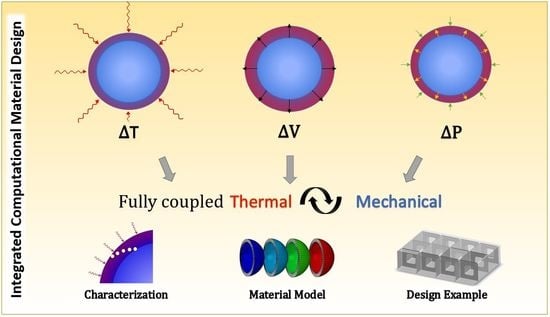
1. Introduction
2. Materials and Methods
2.1. Modeling
Molding Assembly
2.2. Materials and Implementation
2.3. Evaluation
2.4. Experimentation
3. Results and Discussion
3.1. Modeling
3.1.1. Temperature Change
3.1.2. Pressure Change
3.2. Validation
3.3. Sensitivity Analysis
3.4. TRP Design
4. Conclusions
- (1)
- A computational model has been developed based on the previous experimental characterization [29] of TRP. An efficient fully coupled thermomechanical simulation has been formulated from a combination of tested and calculated material and manufacturing assembly parameters. The use of reduced integration elements in both metal and rubber sections reduced the total simulation runtime by approximately 30%, with minimal influence on surface pressures (<1%).
- (2)
- A sensitivity analysis has been conducted on the model to established significant parameters in TRP. The most significant variable in TRP design, based on this investigation, is the designed gap, or spacing between the assembly components. The maximum pressures obtained are highly dependent on the gap. Too small a gap between rubber and mold resulted in large pressures and elastic deformations of the mold; such distortions are often reported as the failure mode of TRP developed through trial and error. A computational model, such as the one presented in this paper, can be used to optimize the gap via inverse parameter identification. Additionally, based on this finding it is recommended that a high-precision mold is used for curing the silicone rubber and that shrinkage is accounted for during the initial curing step.The thermal conductivity is also a significant parameter in the simulation. In this paper, thermal conductivity is back-calculated based on previous experimental data. This method relies on the assumption that the material is homogeneous. For nanocomposite TRP materials, it may be important to measure thermal conductivity more precisely, using techniques such as laser flash analysis (LFA).
- (3)
- A TRP design process has been simulated for a well-established autoclave cure continuous fiber composites prepreg. Using the fully coupled computational model developed in this paper, the full processing simulation was run in less than 10 min on a local computer.
Author Contributions
Funding
Acknowledgments
Conflicts of Interest
References
- Rudd, C.D.; Long, A.C.; Kendall, K.N.; Mangin, C.G.E. Liquid Moulding Technologies: Resin Transfer Moulding, Structural Reaction Injection Moulding and Related Processing Techniques, SAE International; Woodhead Publishing Lt.: Cambridge, UK, 1997. [Google Scholar]
- NIAR. Polymer Matrix Composites Guidelines for Characterization of Structural Materials; Composite Materials Handbook (CMH-17-1G): Volume 1; SAE International: Wichita, KS, USA, 2012. [Google Scholar]
- Stevens, R.P.; Quinn, S.; Veal, R.; Gerrard, S.; Tsimplis, M.; Dulieu-Barton, J.; Thomsen, O. Modernising Composite Materials Regulations: A Position Paper; University of Southampton: Southampton, UK, 2017. [Google Scholar]
- Lapointe, F.; Lebel, L.L. Fiber Damage and Impregnation during Multi-Die Vacuum Assisted Pultrusion of Carbon/PEEK Hybrid Yarns. Polym. Compos. 2019, 40, E1015–E1028. [Google Scholar] [CrossRef]
- Hexcel Corporation. HexPly® M21: Product Data Sheet. 2016. Available online: https://www.alquilujointernacional.eu/wp-content/uploads/2019/01/Caracter%C3%ADsticas-fibra-de-carbono-unidireccional.pdf (accessed on 5 May 2020).
- Black, S. Press-Molding Method Emulates Autoclave: Rubber Tool Insert Avoids Consolidation Pressure “Dead Zones” and Slashes Cost. Available online: https://www.compositesworld.com/articles/press-molding-method-emulates-autoclave (accessed on 8 August 2020).
- Fernlund, G.; Rahman, N.; Courdji, R.; Bresslauer, M.; Poursartip, A.; Willden, K.; Nelson, K. Experimental and numerical study of the effect of cure cycle, tool surface, geometry, and lay-up on the dimensional fidelity of autoclave-processed composite parts. Compos. Part A 2002, 33, 341–351. [Google Scholar] [CrossRef]
- Maistros, G.M.; Partridge, I.K. Monitoring autoclave cure in commercial carbon fibre/epoxy composites. Compos. Part B 1998, 29, 245–250. [Google Scholar] [CrossRef]
- Centea, T.; Grunenfelder, L.K.; Nutt, S.R. A review of out-of-autoclave prepregs—Material properties, process phenomena, and manufacturing considerations. Compos. Part A 2015, 70, 132–154. [Google Scholar] [CrossRef]
- Johnston, A.; Vaziri, R.; Poursartip, A. A Plane Strain Model for Process-Induced Deformation of Laminated Composite Structures. J. Compos. Mater. 2001, 35, 1435–1468. [Google Scholar] [CrossRef]
- Anderson, J.P.; Altan, M.C. Properties of Composite Cylinders Fabricated by Bladder Assisted Composite Manufacturing. J. Eng. Mater. Technol. 2012, 134. [Google Scholar] [CrossRef]
- Renaudin, J.P.; Renard, P. Method of Manufacturing a Golf Shaft of Complex Shape by Internal Bladder Pressurization. U.S. Patent US6071460A, 15 August 1997. [Google Scholar]
- Fink, B.K.; Hsiao, K.-T.; Mathur, R.; Gillespie, J.W.; Advani, S.G. An Analytical Vacuum-Assisted Resin Transfer Molding (VARTM) Flow Model; ARL-TR-2354; Army Research Laboratory: Harford County, MD, USA, 2000. [Google Scholar]
- Wu, D.; Larsson, R.; Blinzler, B. A preform deformation and resin flow coupled model including the cure kinetics and chemo-rheology for the VARTM process. Int. J. Mater. Form. 2020. [Google Scholar] [CrossRef]
- Hatch, D.M.; Larsen, R.J. High Temperature Consolidation Process. U.S. Patent US4409048A, 11 October 1975. [Google Scholar]
- Kemp, D.N. Fixed-Volume, Trapped Rubber Molding Method. U.S. Patent US4889668A, 26 December 1989. [Google Scholar]
- Barraclough, D.J. Molding of Composite Materials. U.S. Patent US4624820A, 25 November 1986. [Google Scholar]
- Baran, I.; Cinar, K.; Ersoy, N.; Akkerman, R.; Hattel, J.H. A Review on the Mechanical Modeling of Composite Manufacturing Processes. Arch Comput. Methods Eng. 2017, 24, 365–395. [Google Scholar] [CrossRef]
- Gray, D.S.; Tien, J.; Chen, C.S. High-Conductivity Elastomeric Electronics. Adv. Mater. 2004, 16, 393–397. [Google Scholar] [CrossRef]
- Keohan, F.K.; Wei, X.F.; Wongsarnpigoon, A.; Lazaro, E.; Darga, J.E.; Grill, W.M. Fabrication and evaluation of conductive elastomer electrodes for neural stimulation. J. Biomat. Sci. 2007, 18, 1057–1073. [Google Scholar] [CrossRef]
- Sanchez-Hidalgo, R.; Blanco, C.; Menendez, R.; Verdejo, R.; Lopez-Manchado, M.A. Multifunctional Silicone Rubber Nanocomposites by Controlling the Structure and Morphology of Graphene Material. Polymers 2019, 11, 449. [Google Scholar] [CrossRef] [PubMed]
- Sarrazin, H.; Kim, B.; Ahn, S.H.; Springer, G.S. Effects of processing temperature and lay-up on springback. J. Compos. Mater. 1995, 29, 1278–1294. [Google Scholar] [CrossRef]
- Gigliotti, M.; Wisnom, M.R.; Potter, D. Development of curvature during the cure of AS4/8552 [0/90] unsymmetric composite plates. Compos. Sci. Technol. 2003, 63, 187–197. [Google Scholar] [CrossRef]
- Johnston, A. An Integrated Model of the Development of Process-Induced Deformation in Autoclave Processing of Composite Structures. Ph.D. Thesis, The University of British Columbia, Vancouver, BC, Canada, 1997. [Google Scholar]
- Bogetti, T.A.; Gillespie, J.W., Jr. Process-induced stress and deformation in thick-section thermoset composite laminates. J. Compos. Mater. 1992, 26, 626–660. [Google Scholar] [CrossRef]
- Ruiz, E.; Trochu, F. Numerical analysis of cure temperature and internal stresses in thin and thick RTM parts. Compos. A 2005, 36, 806–826. [Google Scholar] [CrossRef]
- Young, W.B. Compacting pressure and cure cycle for processing of thick composite laminates. Compos. Sci. Technol. 1995, 54, 299–306. [Google Scholar] [CrossRef]
- Velu, R.; Calais, T.; Jayakumar, A.; Raspall, F. A Comprehensive Review of Bio-Nanomaterials for Medical Implants and Feasibility Studies on Fabrication of Such Implants by Additive Manufacturing Technique. Materials 2020, 13, 92. [Google Scholar] [CrossRef]
- Khalili, P.; Boulanger, T.; Blinzler, B.J. Elastomer Characterization Method for Trapped Rubber Processing. Polymers 2020, 12, 686. [Google Scholar] [CrossRef]
- Mooney, M. A theory of large elastic deformation. J. Appl. Phys. 1940, 11, 582–592. [Google Scholar] [CrossRef]
- Rivlin, R.S. Large elastic deformations of isotropic materials. IV. Further developments of the general theory. Philosophical Transactions of the Royal Society of London. Ser. A Math. Phys. Sci. 1948, 241, 379–397. [Google Scholar]
- Österlöf, R. Modelling the Viscoplastic Properties of Carbon Black Filled Rubber. Ph.D. Thesis, KTH, Stockholm, Sweden, 2016. [Google Scholar]
- Lion, A.; Diercks, N.; Caillard, J. One the directional approach in constitutive modelling: A general thermomechanical framework and exact solutions for Mooney-Rivlin type elasticity in each direction. Int. J. Solids Struct. 2013, 50, 2518–2526. [Google Scholar] [CrossRef]
- Dassault Systèmes®. Abaqus Analysis User’s Manual 6.14; Dassault Systèmes®: Vélizy-Villacoublay, France, 2014. [Google Scholar]
- SKF Sweden AB. Material for Bearing Rings and Rolling Elements. In SKF Material Properties Data Sheet; SKF, Sweden AB: Gothenburg, Sweden, 2019. [Google Scholar]
- Metals Depot®. 6061-T6511 Aluminum Bar, Metals Depot Material Properties Data Sheet2019. Available online: https://www.metalsdepot.com/aluminum-products/aluminum-flat-bar (accessed on 15 February 2019).
- Easy Composites TM. Condensation Cure Silicone Rubber: CS25—Technical Datasheet; Easy Composites Ltd.: Staffordshire, UK, 2018. [Google Scholar]
- Granta Design Limited. Properties of Silicone Rubber. 2001. Available online: https://www.azom.com/properties.aspx?ArticleID=920 (accessed on 12 February 2019).
- Unsworth, J.; Duarte, F.J. Heat diffusion in a solid sphere and Fourier theory: An elementary practical example. Am. J. Phys. 1979, 47, 981. [Google Scholar] [CrossRef]
- Hasselström, A.K.J.; Nilsson, U.E. Thermal Contact Conductance in Bolted Joints; Chalmers University of Technology: Gothenburg, Sweden, 2012. [Google Scholar]
- Cooper, M.G.; Mikic, B.B.; Yovanovich, M.M. Thermal Contact Conductance. Int. J. Heat Mass Transfer 1968, 12, 279–300. [Google Scholar] [CrossRef]
- Babu, K.N. Thermal Contact Resistance: Experiments and Simulation. Master’s Thesis, Chalmers University of Technology, Gothenburg, Sweden, 2015. [Google Scholar]
- Salerno, L.J.; Kittel, P. Thermal Contact Conductance; NASA Technical Memorandum 110429; Ames Research Center: Mountain View, CA, USA, 1997. [Google Scholar]
- Mikic, B.B.; Rohsenow, W.M. Thermal Contact Resistance; Report No. DSR 74542-41; Engineering Projects Lab, MIT: Cambridge, MA, USA, 1966. [Google Scholar]
- Dugasta, G.; Settar, A.; Chetehouna, K.; Gascoin, N.; Marceau, J.L.; Bouchez, M.; De Bats, M. Experimental and numerical analysis on the thermal degradation of reinforced silicone-based composites: Effect of carbon fibres and silicon carbide powder contents. Thermochim. Acta 2020, 686, 178563. [Google Scholar] [CrossRef]


| Property | Value | Units |
|---|---|---|
| Mooney–Rivlin (C1) | 2.50 × 10⁸ | Pa |
| Mooney–Rivlin (D1) | 8.05 × 10⁻¹¹ | Pa |
| Density | 1.049 | g/cm3 |
| Conductivity | 1.9 | W/mK |
| Specific Heat Capacity | 1050 | J/kgK |
| Coefficient of Thermal Expansion | 286 × 10−6 | /K |
| Stainless Steel/Rubber Interface | Aluminum/Rubber Interface | |||
|---|---|---|---|---|
| Conductance (W/K) | Clearance (m) | Conductance (W/K) | Clearance (m) | |
| Gap Conductance | 1.05 | 0 | 4.07 | 0 |
| 0.9 | 0.0025 | 0.9 | 0.0025 | |
| 0.038 | 0.005 | 0.038 | 0.005 | |
| 0 | 0.01 | 0 | 0.01 | |
| Conductance (W/K) | Pressure (Pa) | Conductance (W/K) | Pressure (Pa) | |
| Contact Conductance | 1.05 | 0 | 4.07 | 0 |
| 1.37 | 100 | 5.29 | 100 | |
| 1.78 | 700 | 6.88 | 700 | |
| 32.4 | 1.00 × 10⁶ | 126.25 | 1.00 × 10⁶ | |
| Parameter | Minimum | Maximum | Response |
|---|---|---|---|
| Initial gap | 0.00 mm | 0.02 mm | Changes in final pressure from 17,000 to 0 kPa (Figure 6). |
| Silicone rubber thermal conductivity | 0.2 W/mK [38] | 2.55 W/mK [38] | No change in final pressure, the difference in temperature from the inner surface to the outer surface of the rubber changes from 1.0 °C at the minimum to 0.05 °C at the maximum value. |
| Interface thermal conductance | 0.9 W/K | 250 W/K | No change in final pressure. Using the maximum value, the rubber temperature increase starts 80% earlier and exponent is increased by a power of one compared to the minimum value. |
| Specific heat capacity | 1050 J/k [38] | 1300 J/k [38] | No change in final pressure, less than 0.01% change in the temperature over time. |
© 2020 by the authors. Licensee MDPI, Basel, Switzerland. This article is an open access article distributed under the terms and conditions of the Creative Commons Attribution (CC BY) license (http://creativecommons.org/licenses/by/4.0/).
Share and Cite
Blinzler, B.J.; Khalili, P.; Ahlström, J. Integrated Computational Material Design for PMC Manufacturing with Trapped Rubber. Materials 2020, 13, 3825. https://doi.org/10.3390/ma13173825
Blinzler BJ, Khalili P, Ahlström J. Integrated Computational Material Design for PMC Manufacturing with Trapped Rubber. Materials. 2020; 13(17):3825. https://doi.org/10.3390/ma13173825
Chicago/Turabian StyleBlinzler, Brina J., Pooria Khalili, and Johan Ahlström. 2020. "Integrated Computational Material Design for PMC Manufacturing with Trapped Rubber" Materials 13, no. 17: 3825. https://doi.org/10.3390/ma13173825
APA StyleBlinzler, B. J., Khalili, P., & Ahlström, J. (2020). Integrated Computational Material Design for PMC Manufacturing with Trapped Rubber. Materials, 13(17), 3825. https://doi.org/10.3390/ma13173825