Article

Robust Stabilization of Underactuated Two-Wheeled Balancing Vehicles on Uncertain Terrains with Nonlinear-Model-Based Disturbance Compensation

School of Aerospace and Mechanical Engineering, Korea Aerospace University, Goyang 10540, Republic of Korea
*
Author to whom correspondence should be addressed.
Actuators 2022, 11(11), 339; https://doi.org/10.3390/act11110339
Submission received: 28 October 2022 / Revised: 17 November 2022 / Accepted: 18 November 2022 / Published: 21 November 2022
(This article belongs to the Special Issue Modeling, Optimization and Control of Robotic Systems)

Abstract

:
Two-wheeled inverted pendulum (TWIP) vehicles are prone to lose their mobility and postural stability owing to their inherently unstable and underactuated dynamic characteristics, specifically when they encounter abruptly changed slopes or ground friction. Overcoming such environmental disturbances is essential to realize an agile TWIP-based mobile platform. In this paper, we suggest a disturbance compensation method that is compatible with unmanned TWIP systems in terms of the nonlinear-model-based disturbance observer, where the underactuated dynamic model is transformed to a fully actuated form by regarding the gravitational moment of the inverted pendulum as a supplementary pseudo-actuator to counteract the pitch-directional disturbances. Consequently, it enables us to intuitively determine the disturbance compensation input of the two wheels and the pitch reference input accommodating to uncertain terrains in real time. Through simulation and experimental results, the effectiveness of the proposed method is validated.

1. Introduction

Due to its maneuverability and high payload-to-weight ratio, the two-wheeled inverted pendulum (TWIP), typically with two parallel wheels, is still receiving much attention as a mobile platform for personal transporters [1], autonomous vehicles [2,3], robotic wheelchairs [4], wheeled humanoids [5,6], and wheeled bipedal robots [7]. It belongs to inherently unstable and underactuated systems with fewer actuators than the degrees of freedom needed for their control, which can be justified only when the instability of the pendulum is actively utilized to accomplish agile motions committed to diverse manipulation tasks. Inevitably, it is highly sensitive to external disturbances caused by uncertain environments, and the risk of turnover becomes higher while autonomously driving on unknown surfaces with varying slope and ground friction.
As a matter of fact, the posture control performance of unmanned TWIPs can be greatly improved by modifying the structural design. For example, a movable center of gravity enables more swift movements at the start and stop of the run [8]. The reaction wheel is also effective in compensating for the internal disturbances caused by embedded manipulators [9]. However, the TWIP employing the additional actuators is not an underactuated system anymore and requires paying the price of a much heavier weight and complicated mechanism.
Error-based linear feedback controls such as PID controls and LQRs [10] are certainly limited in covering the wide range of pitch motions that the TWIP robot can experience as the terrain slope and wheel friction are unexpectedly changed. In other words, a set of control gains well-adjusted for a plain does not guarantee postural stability and driving performance on a different slope because the strong nonlinear effect is closely concerned with the pitch motion. The nonlinear control schemes including the adaptive control [11], the Lyapunov-based control [12], the SDRE optimal control [13], etc., can be applied to extend the range of possible pitch angles until the turnover happens. Nonetheless, to make the inverted pendulum motion quickly converge to the equilibrium point, it is desired to adopt an anticipative compensation input to directly cope with the lumped uncertainty, including modeling errors and the external disturbances not considered in the error-based nominal feedback control design.
The preceding results on the robust compensator design of TWIP can be classified into the extended state observer [14], the nonlinear disturbance observer [15], sliding mode control methods [16,17], as well as the combined synthesis of a disturbance observer and a sliding control [18]. These works prove that it is a challenging problem to determine the disturbance compensation input for underactuated systems because they do not have a one-to-one correspondence between the actuators and the degrees of freedom. Despite the rigorous outcomes mostly in terms of Lyapunov-based designs, they are taking rather highly complicated forms of many tuning parameters and switching functions to ensure the asymptotic stability for lumped disturbances. Thus, aside from the mathematical completeness, this could inevitably raise an implementation issue for real systems because the driving performance highly depends on a sophisticated gain-tuning process.
Focusing more on the slope-climbing problem for unmanned TWIP systems, the dynamic equations on an inclined surface were described with respect to the 2D longitudinal motion [19] and the 3D motion [20]. The slope angle of the terrain was estimated by using a disturbance observer in [21]. The effects of the terrain inclination on the stability of TWIP were accounted for in [22]. The reaction torque observer against the ramp disturbances was suggested to determine the equilibrium pitch angle in [23]. A so-called second sliding controller was designed to improve the velocity tracking performance on inclined surfaces in [16]. These examples demonstrate that the terrain uncertainty with an unknown slope is a dominant factor that determines the tracking performance and postural stability of TWIPs.
In this paper, we propose a new solution to tackle the stabilization problem of unmanned TWIP-balancing vehicles in uncertain terrains in terms of the nonlinear-model-based disturbance observer (NDOB). The highlight of this study lies in regarding the gravitational moment acting on the inverted pendulum as a pseudo-actuator and transforming the dynamic model of the underactuated TWIP into a fully actuated one by modulating the input matrix. As relevant performances were carried out through the whole-body coordination control in [5,6,7], how to aggressively utilize the gravity of the pendulum is essential to accomplish the balanced agile motions of a TWIP system. In the previous robust control frameworks [14,15,16,17,18] for underactuated TWIPs, it cannot be clearly described how the disturbance estimates along the forward, pitch, and yaw motions are resolved into the compensation input channels. In contrast, the proposed scheme clarifies that the forward and yaw directional disturbances can be compensated through two input channels, and the body disturbances hindering the pitch motion can be indirectly attenuated in terms of a real-time pitch reference input dealing with the pitch directional disturbance estimates. Thus, the proposed method has the merit of explicitly reflecting the dynamic correlations of the underactuated TWIP by using a compensation input design and making the feedback gain tuning easier.
The rest of this paper is organized as follows: In Section 2, a description is provided in terms of how the unmanned TWIP robot behaves on a ramp while it performs both velocity and posture control at the same time. In Section 3, the related issues in applying the NDOB to the TWIP as an underactuated system are discussed, and finally, an effective compensation strategy for suppressing lumped disturbances is proposed with real-time pitch reference generation. Section 4 is devoted to the driving simulations and experiments on slopes to verify the effectiveness of the proposed method. Finally, conclusions are drawn in Section 5.

2. Dynamic Characteristics of TWIP on Inclined Surfaces
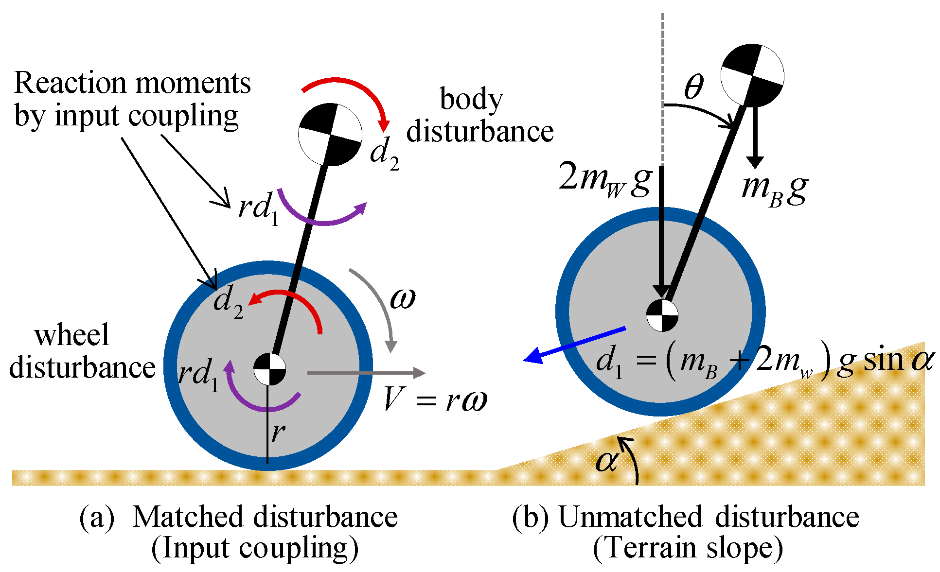
2.1. Dynamic Model

The schematic of the TWIP robot is represented in Figure 1, and the parameters and variables are defined in Table 1, where it has two inputs ( T L , T R ) corresponding to the left and right wheel torques and three outputs ( x , θ , ψ ) to describe the three degrees of freedom. As has been described in [24], seven holonomic and three nonholonomic constraints for the wheeled mobile robot can be considered in formulating the dynamic model of the TWIP. However, it finally leaves the following set of differential equations with respect to the three controlled states of forward velocity, pitch, and yaw rate as
M ( q ) q ¨ + C ( q , q ˙ ) q ˙ + G ( q ) = B τ M ( q ) = [ m 11 m 12 0 m 21 m 22 0 0 0 m 33 ] ,   C ( q , q ˙ ) = [ 0 c 12 c 13 0 0 c 23 c 31 c 32 0 ] G ( q ) = [ g 1 g 2 g 3 ] ,   B = [ 1 / r 1 / r 1 1 d / 2 r d / 2 r ] ,   τ = [ T R T L ]
where q = [ x , θ , ψ ] T is the generalized coordinates, M ( q ) is the inertia matrix, C ( q , q ˙ ) is the Coriolis and centrifugal matrix, G ( q ) is the gravity vector, B is the input matrix, and τ is the input vector. The elements of the matrices and vectors are specified in Appendix A.
Considering the dynamic characteristics of TWIP systems, pitch and forward motions are strongly coupled, as the off-diagonal elements in the first and second row of the inertia matrix indicate, whereas the yaw motion is rarely affected by the other motions, although the Coriolis and centrifugal terms define the correlation among them. Hence, the performances of the pitch and velocity control are highly interdependent since the two states ( x ˙ , θ ) must be simultaneously controlled by sharing the single input of τ = T R + T L from the two wheels in the longitudinal direction, whereas the yaw rate for steering can be independently controlled through the difference between the two wheel torques. If a linear system analysis is conducted for the TWIP around an equilibrium point, the closed-loop transfer function regarding the pitch and velocity control will have the same characteristic equation.
The TWIP robot belongs to the acrobot [25] where the two wheels and the inverted pendulum share the wheel axis as the common rotational hinge, and the wheel actuators are mounted on the chassis as a part of the pendulum body, which results in input couplings between the wheel and the pendulum body due to the reaction torque. When a driving torque is exerted to rotate the wheels, the same amount of reverse torque is delivered to the inverted pendulum, and it brings about a pitch motion. The opposite direction of the first and second row in the input matrix B in Equation (1) indicates the input coupling between the forward and pitch motions. The TWIP mechanism distinctly differs from the pendubot [25] systems, such as a cart–pendulum system, where the wheel torques do not directly work on the pendulum. However, a few studies adopted the cart–pendulum system as the nominal model of the TWIP [26].

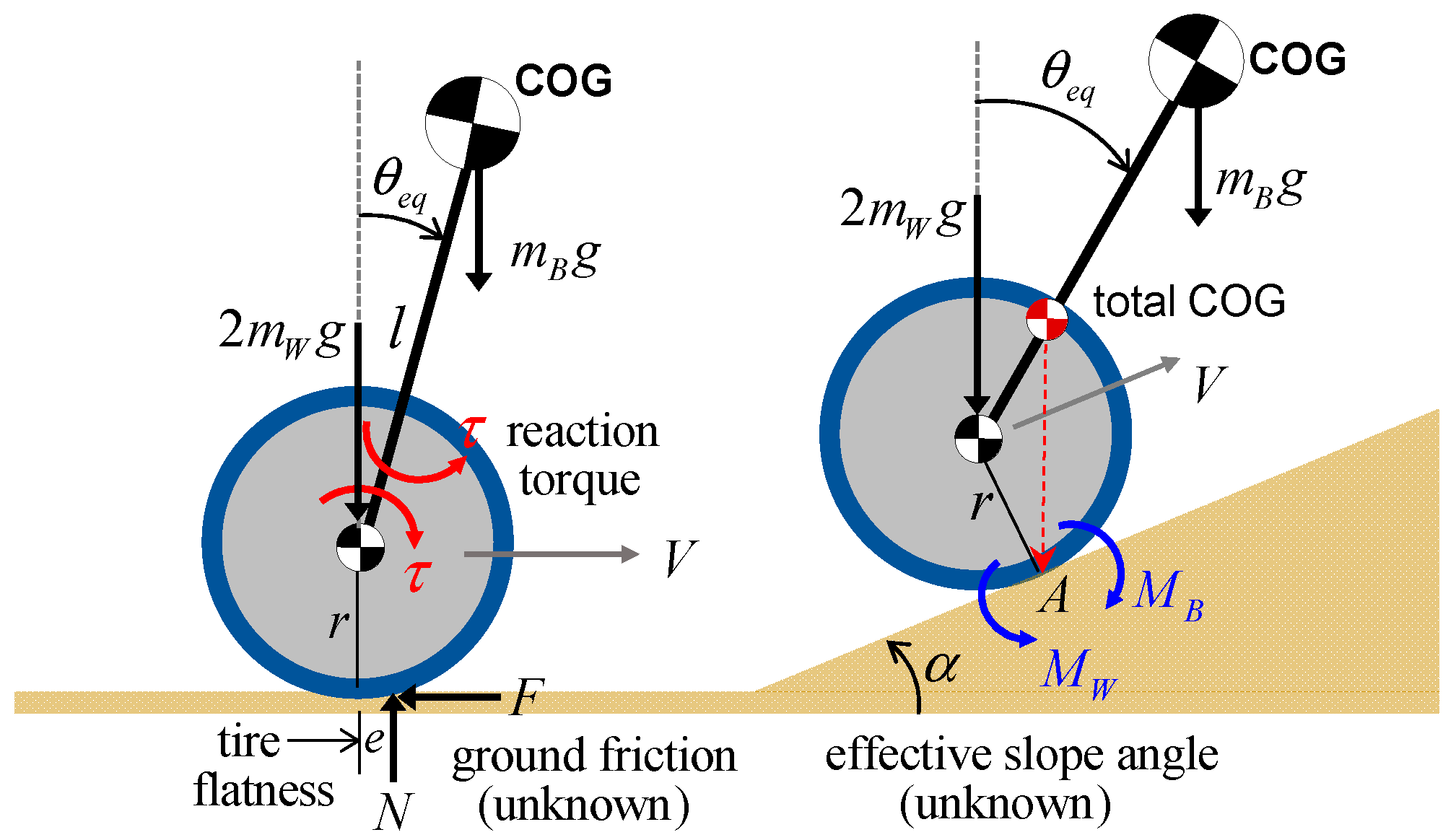
2.2. Finding Static Equilibrium Point on Inclined Surfaces

For a quick understanding of the effect of uncertain terrains with an arbitrary slope angle and surface friction, the longitudinal motion of the TWIP is represented in Figure 2. If the TWIP robot keeps its static equilibrium state on a slope at a constant speed or standstill, the sum of the gravitational moments with respect to the contact point by the weights of the wheels and the inverted pendulum body is equal to zero. That is,
M A = M w M B = 2 m w g r sin α m B g ( l sin θ r sin α ) = ( m B + 2 m w ) g r sin α m B g l sin θ = 0
Then, we have the equilibrium pitch angle against the slope as
θ e q = sin 1 [ ( m B + 2 m w ) r m B l sin α ]
The above relationship holds by assuming a point contact between the wheels and the ground surface. As denoted in the left of Figure 2, even when the TWIP is moving with a constant speed on a plane, it has a nonzero equilibrium pitch angle because of the tire flatness and ground friction. Hence, the time-varying slope angle on the right of Figure 2 can be regarded as an effective ramp disturbance including the frictional effect in the longitudinal direction.
When the TWIP mobile robot meets an unexpected slope, it slows down in uphill climbing and accelerates downhill. To surmount the ramp disturbances, the pitch angle of the inverted pendulum must be swiftly transferred near the equilibrium point. In the case of human-riding TWIP transporters, a skillful rider can readily travel on a ramp by leaning the pitch angle of the body to find the equilibrium point. In other words, the human rider is involved in the control loop as an additional actuator to supplement the underactuated inverted pendulum. However, the safety, and the driving performance of the unmanned TWIP mobile robot on uncertain terrains, highly depend on how quickly the equilibrium pitch angle can be found by the control system against the ramp disturbances.

2.3. Limit of Error-Based Feedback Control

As a typical error-based feedback controller, the PID control law has the robustness property for a certain range of biased disturbances and are widely applied in practical systems. However, a TWIP robot on a slope is a good example where the error-based controls with a fixed gain setting, including linear and nonlinear schemes, show performance limitations. Since the pitch and forward motions of the TWIP are dynamically coupled, and their control performances are in a trade-off relationship, it is time-consuming to attain the final gains satisfying both performances even in numerical simulations. Moreover, the optimal values of the gain setting are varied depending on the inclination of the terrain, because the equilibrium point of the pitch angle is accordingly moved.
The simulation result in Figure 3 compares the uphill driving performance of the prototype in Figure 1 when the velocity reference is 1 m/s, and the PID control is applied with the same gain setting adjusted for the flat surface, where the TWIP robot meets the slopes with different angles at 4 s. When the integral control action is activated, the pitch angle finally converges to the equilibrium point according to the relationship in Equation (3), and although the zero-pitch reference is assigned for the unknown terrain, the velocity tracking performance is greatly degraded as the slope angle increases. This means that the PID controller is vulnerable to ramp disturbances, mainly because it takes some time to reach the pitch equilibrium point, and usually puts more weight on the conservative pitch control gains for the safety of the TWIP from turnovers.
As another example, Figure 4 shows the experimental results for the prototype, where the two cases concerned with the gain tuning issue are compared, while the robot is accelerated and decelerated on a flat surface. Case 1 employs the control gains that give more weight to the pitch control than the velocity tracking performance, whereas Case 2 is the opposite. Naturally, Case 2 with a velocity-weighted controller shows a better tracking performance, but it accompanies a large pitch motion to make the robot rapidly accelerate and decelerate by utilizing the gravity of the inverted pendulum. The pitch-weighted control of Case 1 is advantageous in keeping the upright posture of the robot, but it sacrifices swift velocity tracking. In summary, when an error-based feedback controller is applied, the velocity tracking performance and the posture stabilization of the inverted pendulum are irreconcilable on uncertain terrains unless the pitch equilibrium point is given in real time.

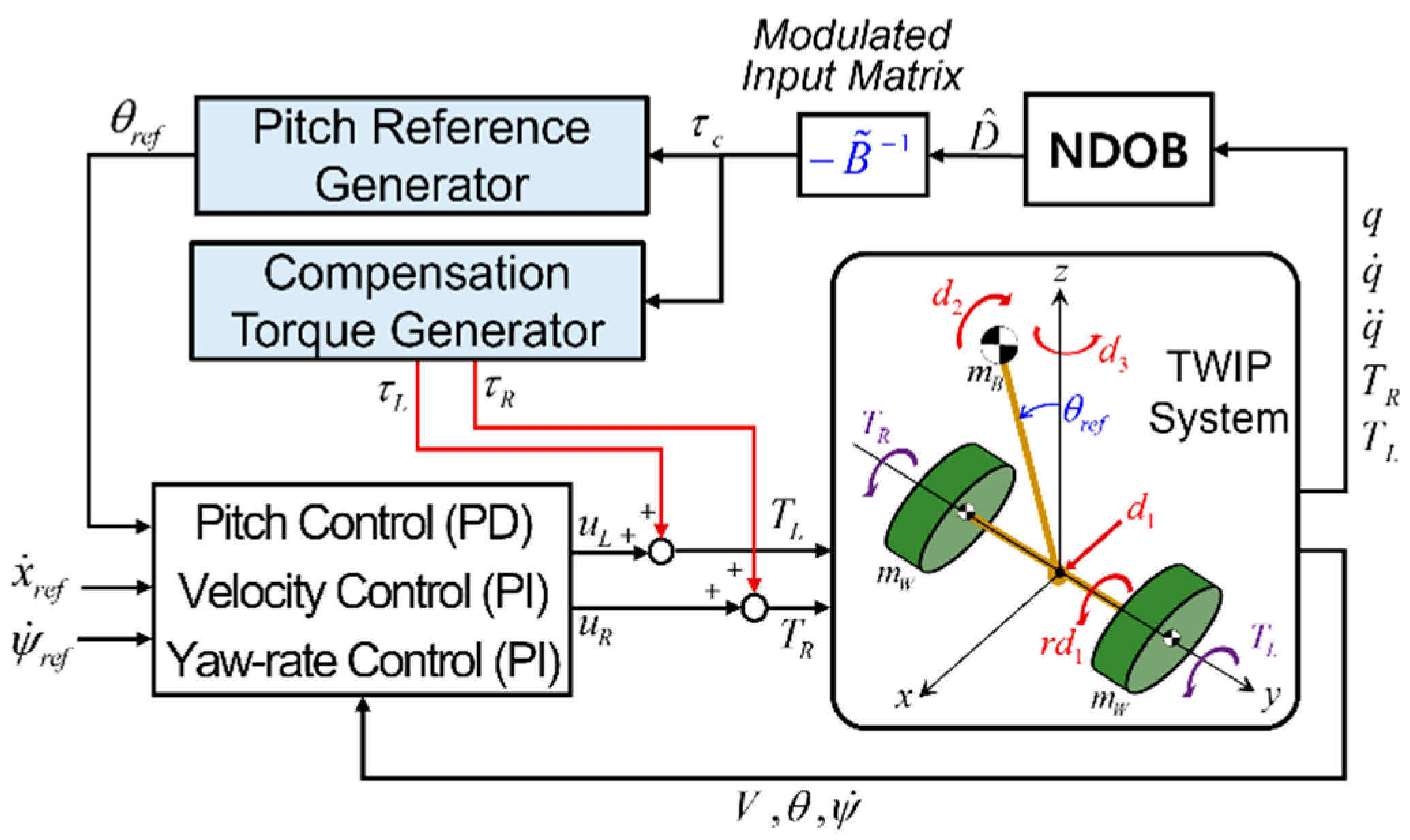
3. NDOB-Based Disturbance Compensation

3.1. NDOB Application to Underactuated TWIPs

A great merit of applying the disturbance observer technique is that it can deal with the lumped disturbance, including the model’s parametric uncertainties and external disturbances, and it allows for the freedom to maintain the current nominal feedback controller, whether it is a linear scheme or a nonlinear one [27]. Considering the strong nonlinear dynamic characteristics of the inverted pendulum, which could happen due to the wide pitch variations against the ramp disturbances, it is reasonable to adopt a nonlinear disturbance observer (NDOB) directly based on differential equations rather than a transfer-function-based linear observer.
Although there exist a few different versions in the NDOB formulations depending on the incorporated state equations and filtering structure [27,28,29], the fundamental notion is that the lumped disturbance at the current time can be equivalently estimated using the nominal model as
D ^ ( t ) = Q · [ M q ¨ ( t ) + C q ˙ ( t ) + G ( t ) B τ ( t λ ) ]
under the assumption that the input variation between the control intervals λ is very small, i.e., τ ( t ) τ ( t λ ) , and all the states are available. The linear operator Q represents a low-pass filter to suppress the high-frequency noises in sensor signals and data. One of the main issues in implementing Equation (4) is how to construct the acceleration terms since the acceleration data are not available in most robotic systems. To eliminate the requirement of any acceleration measurement, an auxiliary variable vector was used in the modified NDOB [29], and the setup of the relevant parameters of the TWIP was developed in [15]. In reality, the acceleration data can be obtained by applying filtered derivatives to the joint measurements, and it works well, as the mobile robot is traveling near a constant speed without high maneuvers.
Prior to establishing a disturbance rejection scheme based on the NDOB, we need to ascertain the drawback of the conventional NDOB in applying it to the underactuated TWIP systems. The dynamic model for the underactuated TWIP in Equation (1) can be rewritten by considering the lumped disturbance reflecting all the internal and environmental uncertainties other than the nominal parameters as
M n × n ( q ) q ¨ + C n × n ( q , q ˙ ) q ˙ + G n × 1 ( q ) = B n × r τ r × 1 + D n × 1 D n × 1 = d m n × 1 + d u n × 1 = B n × r τ d r × 1 + d u n × 1
where r = 2 is the number of inputs, n = 3 is the number of outputs, and D = [ d 1     d 2     d 3 ] T is the lumped disturbance with three elements, which can be defined as the wheel disturbance for the forward motion of the two wheels, the body disturbance for the pitch motion of the inverted pendulum, and the yaw disturbance for the steering motion, respectively. Again, the lumped disturbance vector can be divided into the matched disturbance d m , satisfying the matching condition, and the unmatched disturbance d u , which does not exist in the column space of the input matrix in Equation (1). In Equation (5), τ d can be thought of as the transformation of the matched disturbance into the input channels.
To determine the compensation torques for the disturbance estimates through the input channels, the compensation input τ c must satisfy the relationship of B τ c = D ^ = [ d ^ 1     d ^ 2     d ^ 3 ] T . However, the nonsquare input matrix has only the left inverse B + = ( B T B ) 1 B T since the number of rows is larger than the columns. Then, if the conventional NDOB compensation input τ c = B + D ^ is applied, the compensation error is equivalent to
D ~ D D ^ = D + B τ c = D B B + D ^ = ( B τ d + d u ) B B + ( B τ ^ d + d ^ u ) = ( B τ d B ( B + B ) τ ^ d ) 0 + ( d u B B + d ^ u )
where the first part corresponding to the matched disturbance can be almost rejected since B + B = I , but the residual compensation error caused by the unmatched disturbance still perturbs the system response since B B + I .
On the other hand, by taking the left pseudo-inverse of the input matrix in Equation (1), we have
D ~ = D B B + D ^ = [ d 1 1 ( 1 + r 2 ) d ^ 1 + r ( 1 + r 2 ) d ^ 2 d 2 r 2 ( 1 + r 2 ) d ^ 2 + r ( 1 + r 2 ) d ^ 1 d 3 d ^ 3 ]
As the first and second elements represent, the wheel disturbance and the body disturbance cannot be clearly attenuated, because when both estimates are transferred to the underactuated input channels, they are directly correlated by the input coupling of the acrobot. The last yaw disturbance compensation error is not affected by the other two compensation elements since the yaw motion is free of the input coupling. However, if the lumped disturbance of the TWIP satisfies the matching condition, the relationship of d ^ 2 = r d ^ 1 holds, as depicted in Figure 5. A simple example of the matched disturbance is the viscous and Coulomb friction exerted on the wheel axis. In this case, the compensation error Equation (7) is reduced to
D ~ = [ d 1 d ^ 1       d 2 d ^ 2       d 3 d ^ 3 ] T
which indicates that the matched disturbances are completely rejected through the input channels if all the states in Equation (4) can be exactly reconstructed in real time.
A great part of the lumped disturbance acting on the TWIP robot can be classified as unmatched disturbances, e.g., model parametric errors, rolling resistance due to the tire flatness, wheel–slip phenomena, the eccentric center of the gravity of the pendulum from the wheel axis, and most importantly, the environmental disturbance by the inclined terrains. If the effective slope angle in Figure 2 is considered in the nominal model Equation (1), the pitch angle θ in the elements of matrices of M and C is changed to θ + α , as shown in Appendix A, and the first element of the gravity vector has g 1 = ( m B + 2 m W ) g sin α [16,20]. As the static equilibrium condition in Equation (2) implies, this additional gravity term arising from the unknown terrain, as denoted in Figure 5, dominantly affects the velocity tracking performance and the upright posture stabilization of the TWIP as a wheel disturbance. Assuming only a ramp disturbance due to terrain uncertainty, the lumped disturbance of the TWIP at a steady state can be represented by
D r a m p = [ ( m B + 2 m W ) g sin α 0 0 ]
The above disturbance certainly does not satisfy the matching condition because it does not exist in the column space of the input matrix. In other words, it cannot be expressed as a linear combination of the column vectors of B in Equation (1).

3.2. Disturbance Rejection by Input Matrix Modulation

As we have seen, the conventional NDOB techniques generating equivalent compensation torques to the lumped disturbances through the input channels are fundamentally limited in attenuating the unmatched disturbances of underactuated systems. Related to this issue, the NDOB-combined sliding mode controls employed the so-called dynamic surface in [15], and a novel sliding surface in [18], to achieve an asymptotically stable sliding mode for unmatched disturbances. Additionally, the second sliding controller in [16], the integral-type sliding surface suggested in [17] for TWIP systems, and the second-order sliding control suggested for underactuated systems in [30] belong to this class. However, the chattering problem due to the switching control action is unavoidable when the behavior of the TWIP deviates far from the nominal sliding dynamics, and the complicated parameters and gain structures, which were inevitable to guarantee the Lyapunov stability, would be a great barrier to find an appropriate gain setting for the stable convergence of the inverted pendulum to the equilibrium point.
Compared with nominal error-based feedback controls, the above-mentioned robust control schemes can significantly contribute to the stabilization of underactuated TWIPs as the system’s uncertainty increases. However, it will reach a certain limit of velocity tracking performance if the zero-pitch reference is kept for unknown ramp disturbances because it intrinsically violates the static equilibrium condition in Figure 2. Although the center of gravity (COG) movement of the inverted pendulum, along with the pitch motion, bothers the upright posture of the TWIP, it must be actively utilized to implement high-maneuver manipulations in terms of the balanced mobile platform and keep the static equilibrium state on inclined surfaces.
The inverted pendulum body of TWIP systems can be regarded as a gravitational actuator if the pitch motion is fairly stabilized all the time. The whole-body controls in [5,6,7] are good examples utilizing the gravity of the inverted pendulum. However, they can be enabled only when appropriate pitch references are given for the center of gravity through an extra planning process. In this regard, a dynamic-model-based trajectory in [31] has been proposed for swift velocity transition on flat surfaces. In this paper, we suggest how the real-time pitch reference of the TWIP accommodating to uncertain terrains can be generated in terms of the NDOB. First, the gravity term of the nominal model in Equation (1) is merged into the input vector by regarding it as a pseudo-actuator. Then, we have
M ( q ) q ¨ + C ( q , q ˙ ) q ˙ = B ~ u + D B ~ = [ 1 / r 1 / r 0 1 1 1 d / 2 r d / 2 r 0 ] ,   u = [ T R T L m B g l sin θ ] ,   D = [ d 1 d 2 d 3 ]
where the modulation of the input matrix into a full-rank and square one temporarily makes the TWIP system a fully actuated system. Then, the compensation input satisfying the relationship of B ~ τ c = D ^ for the disturbance estimates in terms of a specific NDOB formulation can be determined by
τ c = [ τ R τ L m B g l sin θ r e f ] = B ~ 1 D ^ = [ ( r 2 d ^ 1 + r d d ^ 3 ) ( r 2 d ^ 1 r d d ^ 3 ) ( r d ^ 1 + d ^ 2 ) ]
Hence, the compensation input consists of two direct torque inputs ( τ R , τ L ) for the right and left wheels and an indirect gravitational moment, which can be generated in real time by assigning the pitch reference input as follows:
θ r e f = sin 1 ( r d ^ 1 + d ^ 2 m B g l )
which satisfies a dynamic equilibrium between the disturbance input and the gravitational moment. Then, as far as the pitch control loop successfully follows the pitch reference, we have the disturbance compensation error, D ~ = D B ~ B ~ 1 D ^ = D D ^ in the same form as Equation (8) instead of Equation (7). As shown, the wheel disturbance as well as the body disturbance, as defined in Equation (5), are involved in the equilibrium condition according to the input coupling effect. If only the uncertain slope is considered as a dominant disturbance denoted in Equation (9), and the TWIP is moving at a constant speed, the pitch reference is supposed to be coincident with the equilibrium pitch angle in Equation (3). On the other hand, it goes to zero when it meets d ^ 2 = r d ^ 1 for the matched disturbances depicted in Figure 5. However, this happens only if the wheels make a point of contact when traveling on flat surfaces, which cannot occur in reality.
Some researchers investigated how to generate a pitch reference for the smooth climbing of the TWIP on inclined surfaces. For example, state estimators including the slope angle [21] and a pitch angle disturbance observer [23] were synthesized based on the linear models around the equilibrium point. However, they are inadequate to cover a wide range of pitch motions, which can arise via abrupt slope changes and other heavy disturbances. Above all, the current formulation has the merit of consistently generating the torque compensation input and the real-time pitch reference input simultaneously, without an extra trajectory planner and irrespective of the disturbance estimation algorithm.
The overall schematic of the proposed dynamic compensation scheme is represented in Figure 6, where the disturbances associated with the forward and yaw motions are attenuated by the torque compensation inputs of the two wheels according to Equations (4) and (11), and the body disturbance is suppressed as the pitch control loop is activated with the pitch reference assignment according to Equation (12). Separately from the disturbance compensation input, the nominal feedback control loop for the three-degree-of-freedom motion is fundamentally based on the error-based PID control logic. The velocity and steering commands ( x ˙ r e f , ψ ˙ r e f ) can be given arbitrarily, but the pitch reference command θ r e f is highly dependent upon the terrain’s condition. When the controllers for the velocity, pitch, and yaw motion are generated as ( u x , u θ , u ψ ) , respectively, the nominal control inputs of the right and left wheels can be determined by
u R = u x + u θ + u ψ 2 ,   u L = u x + u θ u ψ 2
As indicated, if the pseudo-fully actuated system model in Equation (10) is incorporated in the NDOB-based compensator design, it does not discriminate the matched and unmatched disturbances, and the relationship between the disturbance estimates and compensation inputs becomes clarified. Applying it to TWIP systems, the complicated design issues in [15,16,17,18] concerning multiple sliding surfaces and switching control gains to ensure the robust stability of underactuated systems can be much reduced.

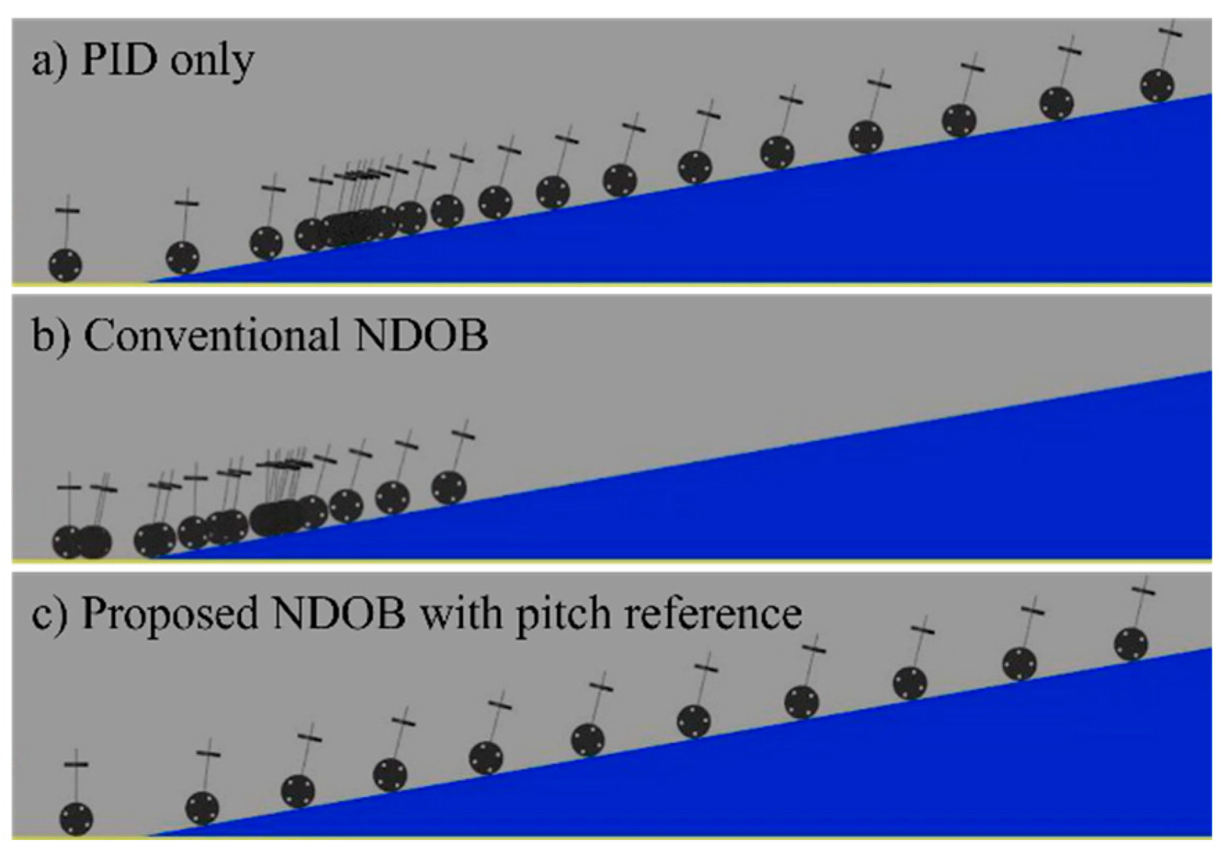
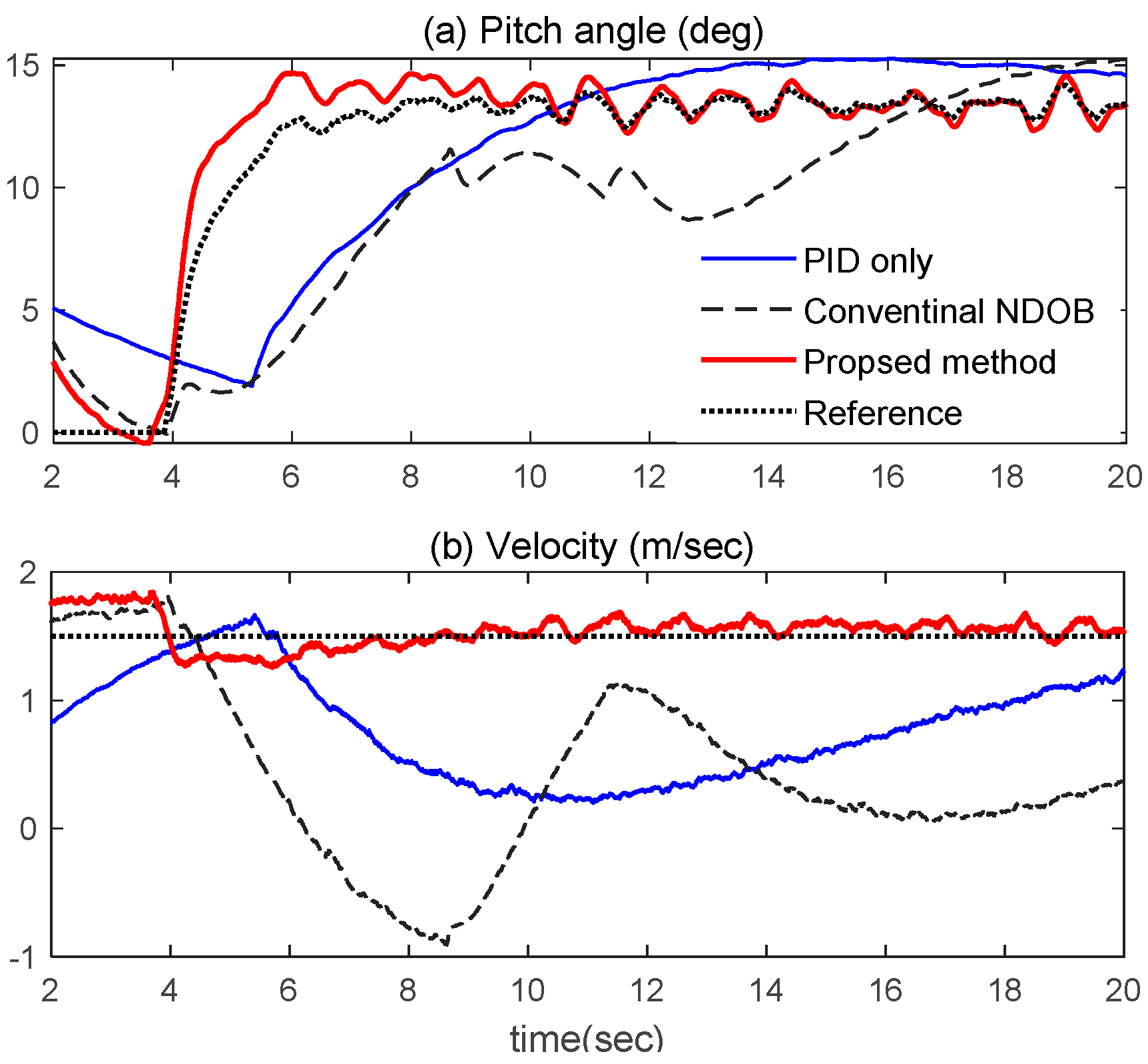
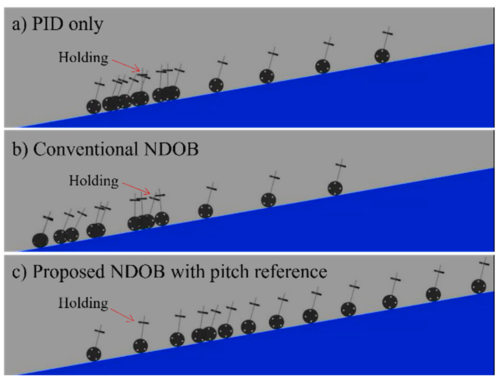
4. Numerical Simulations

To demonstrate the robustness of the proposed technique with respect to uncertain terrains with arbitrary slopes, comparative simulations were carried out using the Simscape Multibody Toolbox [32]. This software provides a dynamic simulation environment for multibody systems and useful tools for modeling the spatial contact force between the wheels and driving surfaces based on the stick–slip friction model. The parameters of the prototype TWIP mobile robot are given in Table 2. The PID controller was applied as a nominal controller for the forward velocity, the pitch angle, and the yaw rate for steering. The gain setting of the nominal controller was adjusted for smooth traveling on plains with more weighting on keeping the upright posture, as previously mentioned in Section 2.3. The video clips related to the simulation results in Figure 7, Figure 8, Figure 9 and Figure 10 can be found at https://youtu.be/YqzDefO85s8 (accessed on 25 May 2022).
Firstly, as shown in Figure 7 and Figure 8, the TWIP had a reference velocity of 1.5 m/s, and it entered the ramp with an unknown slope at around 4 s. (1) In the case of only the PID controller with no pitch reference, the velocity tracking performance deteriorated as soon as the robot encountered the ramp disturbance. For smoothly climbing an inclined surface, the pitch angle of the inverted pendulum had to be transferred to a new equilibrium point as the feedback control was activated. Although the robot managed to climb the ramp again owing to the integral control action, it took quite a long time until the final velocity reached the reference value; (2) when a conventional NDOB compensation input was added to the nominal controller, the tracking performance was more degraded. This is mainly because the reaction torque delivered to the pendulum body in response to the compensation input occurred at the pitch-up moment, and it hindered the pitch motion from reaching the equilibrium point; (3) finally, when the proposed compensation method was applied, it generated the pitch references for the inverted pendulum in real time to keep the equilibrium state compatible to the inclined surface, and it caused the robot to steadily ascend the uncertain slope following the reference velocity.
Secondly, as shown in Figure 9 and Figure 10, as the TWIP robot steadily climbed the ramp, the velocity reference changed from 1.5 m/s to 0 m/s at 10 s to hold a stationary state for 3 s. (1) When applying only the PID controller with a zero-pitch reference, it had great difficulty in making the robot stand still on a ramp. As indicated in Figure 10a, when the zero-velocity command was assigned, it tended to recover the upright posture, which resulted in a severe retreat of the TWIP owing to the gravitational moment acting on the wheels; (2) the compensation input by the conventional NDOB was not helpful at all to keep the standstill position, because the residual disturbance in Equation (7) due to the input couplings continually perturbed the forward and pitch motion at the same time; (3) the proposed NDOB with the real-time pitch reference generation enabled us to have a smooth stop and restart during the uphill movement.
As indicated in Section 2.3, even if a PID controller is applied, a steady traveling of the TWIP on a specific slope can be realized by sophisticated gain tuning for the uphill or downhill driving with more emphasis on the tracking performance rather than keeping the upright posture. However, it does not guarantee an identical transient performance on a different slope and accompanies poor postural stability for unexpected body disturbances, because the static equilibrium point of the inverted pendulum moves according to the varying slope.
For uphill traveling with ramp disturbances, another practical issue that must be considered about the PID controller, as a representative error-based nominal controller, is the actuator saturation problem induced by a long-time accumulation of tracking errors. Although the integral control function is indispensable for overcoming the gravitational effect, it could invoke a large overshoot and rapid increase in velocity as soon as the ramp disturbance vanishes. An anti-windup scheme, such as the clamping technique in [33], can be applied to solve this problem. In contrast, the NDOB-based robust compensation method proposed in this paper greatly relaxes the burden of the nominal feedback gains to achieve a consistent tracking performance regardless of the terrain condition. Additionally, it makes the nominal PID controller free of the anti-windup issue since the additional disturbance compensation input fundamentally has an integral control property to counteract gravitational disturbances. Thus, it enables us to apply moderate velocity gains, and even the integral function can be excluded from the nominal controller.

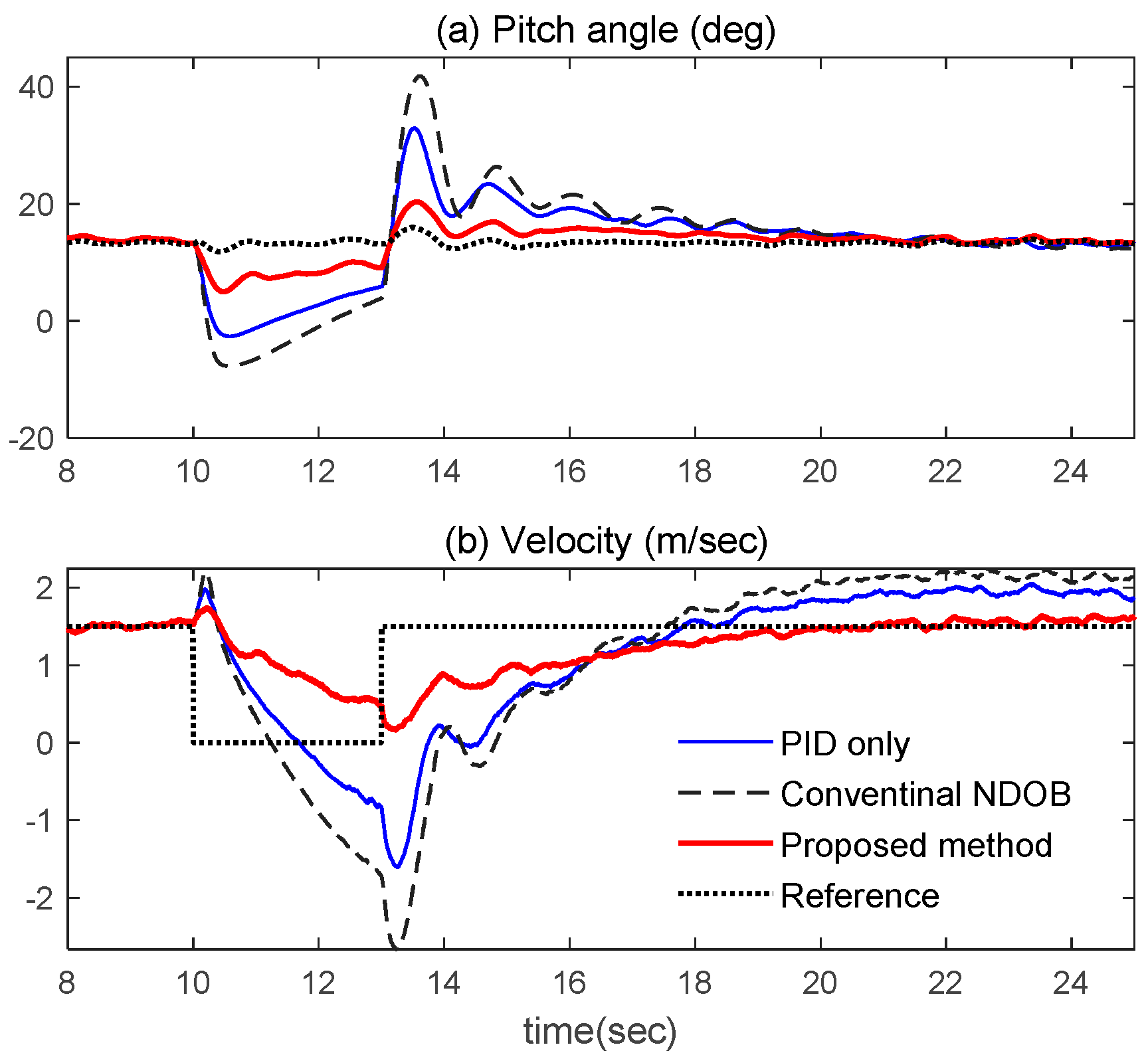
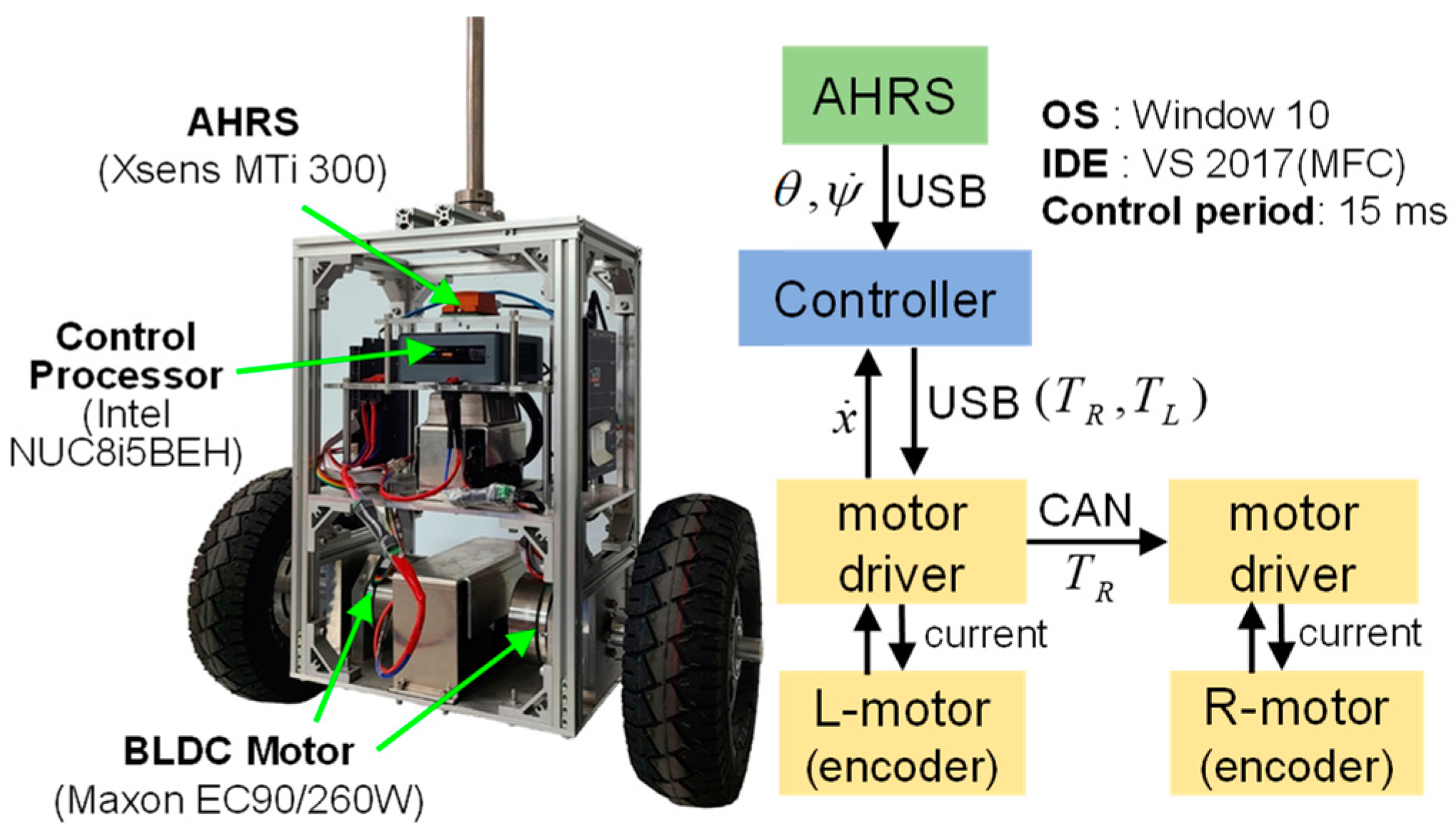
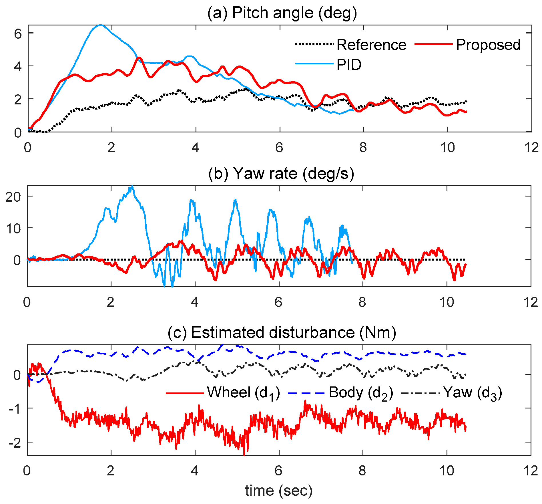
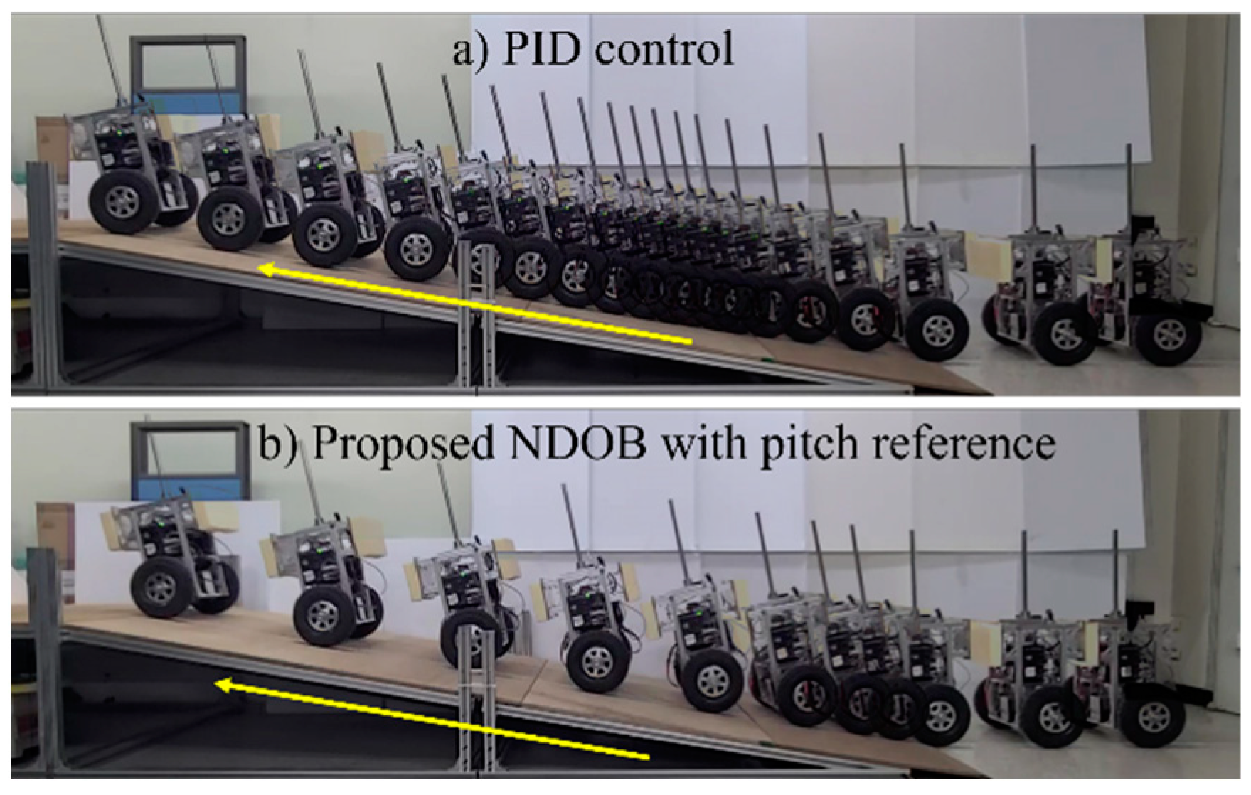
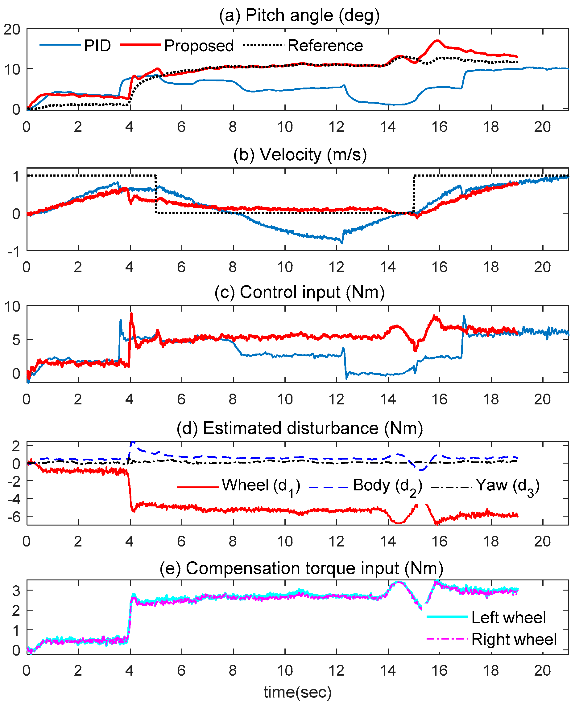
5. Experimental Results

The prototype in Figure 11 had the same nominal parameters as those listed in Table 2. The experiments were classified into three cases: (1) standing still on a flat surface for an arbitrary longitudinal eccentricity as a dominant body disturbance; (2) straight traveling on a flat surface for a lateral eccentricity as a dominant yaw disturbance; (3) velocity tracking on a ramp as a dominant wheel disturbance. The video clips related to the experimental results in Figure 12, Figure 13, Figure 14, Figure 15, Figure 16 and Figure 17 can be found at https://youtu.be/fvrYeNSiiH4 (accessed on 25 May 2022).
As shown in Figure 12, while the robot was holding its upright posture on the plane, a dummy weight was placed on the body to make a longitudinal eccentricity of the COG with respect to the wheel axis. When the PID control was the only function to stabilize the pitch motion, the robot drifted away quite a long distance from the initial position until the feedback system made the pitch angle converge to the new equilibrium point. However, when the proposed NDOB compensation scheme was activated, the moving distance was minimal owing to the prompt generation of the pitch references shown in Figure 12a. The symmetrical shape of the disturbance estimates in Figure 12c for the longitudinal motion of the wheel and body indicated the input coupling of the acrobot.
As shown in Figure 13, the COG of the pendulum was intentionally biased in the lateral direction. As a result, it predominantly worked as a yaw disturbance. Without the yaw attitude control, the lateral eccentric effect made the robot deviate far from the straight line in a short period of time when it was only under the PID yaw-rate control. In contrast, the proposed dynamic compensator prevented the robot from drifting by producing the appropriate torque compensation input for the yaw disturbance. On the other hand, the estimates in Figure 13c corresponding to the wheel and the body disturbances were mainly derived from the parametric errors due to the extra dummy weight.
An uphill driving experiment was then conducted to validate the robustness of the proposed scheme for uncertain terrains. As shown in Figure 14 and Figure 15, the TWIP robot met the inclined surface while driving on a flat plain with a reference velocity of 0.5 m/s and climbed the ramp with an unknown slope of 10 degrees. The results were almost the same as anticipated in the simulation studies. With only the nominal PID controller, the TWIP robot could hardly travel on a ramp since it took quite some time to reach the static equilibrium corresponding to the slope. Although a little slowdown of the speed occurred at the uphill entry, the proposed method enabled the TWIP to steadily climb the ramp by combining the quick generation of the pitch equilibrium angle and the torque compensation input in Equation (11). In the downhill phase, the situation was reversed. Under only the PID control, the robot greatly accelerated, due to the gravitational effect, until the pitch angle converged to the equilibrium point, but the real-time pitch reference in terms of the NDOB prevented a rapid increase in speed and achieved steady downhill movement.
Finally, as shown in Figure 16 and Figure 17, a zero-velocity command was given to the robot for 10 s in the middle of climbing. As shown, using the PID controller without an appropriate pitch reference generation, holding a standstill position on an unknown slope was almost impossible for the underactuated TWIP robot. However, in the NDOB-based robust control approach, the ramp disturbance could be promptly detected, and the posture control performance could be greatly improved by assigning the time-varying pitch reference according to the real-time disturbance estimates.

6. Conclusions

Compared with the previous results on the robust control of the TWIP as an underactuated system, a great merit of the proposed method lies in its physical intuitiveness in drawing the compensation input to tackle uncertain terrains. A sound understanding of the static equilibrium on the slope, the input coupling of the acrobot, and the performance limit of conventional NDOBs for unmatched disturbances led to the establishment of a clear relationship between the disturbance estimates and the compensation input. In addition to unmanned, two-wheeled balancing vehicles, the dynamic compensation scheme developed in this paper can be effectively applied to enhance the control capabilities of wheeled humanoids and mobile manipulators, which are fundamentally based on the TWIP technology, specifically when they are performing on uncertain terrains.

Author Contributions

Conceptualization, Y.K.; formal analysis, Y.K.; funding acquisition, S.K.; investigation, Y.K. and S.K.; methodology, Y.K.; project administration, S.K.; software, Y.K.; supervision, S.K.; writing—original draft preparation, Y.K.; writing—review and editing, S.K. All authors have read and agreed to the published version of the manuscript.

Funding

This work was supported by the National Research Foundation of Korea, grant number NRF-2022R1F1A1073383.

Conflicts of Interest

The authors declare no conflict of interest.

Appendix A

Elements of the Matrices and Vectors in Equation (A1)

m 11 = m B + 2 m w + 2 J / r 2 m 12 = m 21 = m B l cos θ m 22 = m B l 2 + I 2 m 33 = I 3 + 2 K + ( d 2 / 2 ) ( m w + J / r ) ( I 3 I 1 m B l 2 ) sin 2 θ c 12 = ( m B l sin θ ) θ ˙ 2 ,   c 13 = ( m B l sin θ ) ψ ˙ 2 c 23 = ( I 3 I 1 m B l 2 ) ( sin θ cos θ ) ψ ˙ 2 c 31 = ( m B l sin θ ) ψ ˙ x ˙ c 32 = 2 ( I 3 I 1 m B l 2 ) θ ˙ ψ ˙ g 1 = g 3 = 0 g 2 = m B g l sin θ

References

  1. Segway, A. Two-Wheeled Self-Balancing Personal Transporter. Available online: https://en.wikipedia.org/wiki/Segway (accessed on 25 May 2022).
  2. Personal Urban Mobility and Accessibility (PUMA). Available online: https://en.wikipedia.org/wiki/Personal_Urban_Mobility_and_Accessibility (accessed on 17 November 2022).
  3. Vermeiren, L.; Dequidt, A.; Guerra, T.M.; Rago-Tirmant, H.; Parent, M. Modeling, control and experimental verification on a two-wheeled vehicle with free inclination: An urban transportation system. Control Eng. Pract. 2011, 19, 744–756. [Google Scholar] [CrossRef]
  4. Takahashi, Y.; Kohda, M. Human riding experiments on soft front wheel raising of robotic wheelchair with inverse pendulum control. In Proceedings of the 2005 IEEE International Conference on Industrial Technology, Hong Kong, China, 14–17 December 2005; pp. 266–271. [Google Scholar]
  5. Boston Dynamics. Available online: https://www.bostondynamics.com/legacy (accessed on 25 May 2022).
  6. Zafar, M.; Hutchinson, S.; Theodorou, E.A. Hierarchical optimization for whole-body control of wheeled inverted pendulum humanoids. In Proceedings of the 2019 International Conference on Robotics and Automation (ICRA), Montreal, QC, Canada, 20–24 May 2019; pp. 7535–7542. [Google Scholar]
  7. Klemm, V.; Morra, A.; Gulich, L.; Mannhart, D.; Rohr, D.; Kamel, M.; de Viragh, Y.; Siegwart, R. LQR-Assisted Whole-Body Control of a Wheeled Bipedal Robot With Kinematic Loops. IEEE Robot. Autom. Lett. 2020, 5, 3745–3752. [Google Scholar] [CrossRef]
  8. Huang, J.; Ding, F.; Fukuda, T.; Matsuno, T. Modeling and velocity control for a novel narrow vehicle based on mobile wheeled inverted pendulum. IEEE Trans. Control Syst. Technol. 2013, 22, 1607–1617. [Google Scholar] [CrossRef]
  9. Larimi, S.R.; Zarafshan, P.; Moosavian, S.A.A. A New Stabilization Algorithm for a Two-Wheeled Mobile Robot Aided by Reaction Wheel. J. Dyn. Syst. Meas. Control 2014, 137, 011009. [Google Scholar] [CrossRef]
  10. Chan, R.P.M.; Stol, K.A.; Halkyard, C.R. Review of modelling and control of two-wheeled robots. Annu. Rev. Control 2013, 37, 89–103. [Google Scholar] [CrossRef]
  11. Li, Z.; Yang, C. Neural-Adaptive Output Feedback Control of a Class of Transportation Vehicles Based on Wheeled Inverted Pendulum Models. IEEE Trans. Control Syst. Technol. 2011, 20, 1583–1591. [Google Scholar] [CrossRef]
  12. Ravichandran, M.T.; Mahindrakar, A. Robust Stabilization of a Class of Underactuated Mechanical Systems Using Time Scaling and Lyapunov Redesign. IEEE Trans. Ind. Electron. 2010, 58, 4299–4313. [Google Scholar] [CrossRef]
  13. Kim, S.; Kwon, S. Nonlinear Optimal Control Design for Underactuated Two-Wheeled Inverted Pendulum Mobile Platform. IEEE/ASME Trans. Mechatron. 2017, 22, 2803–2808. [Google Scholar] [CrossRef]
  14. Canete, L.; Takahashi, T. Disturbance compensation in pushing, pulling, and lifting for load transporting control of a wheeled inverted pendulum type assistant robot using the extended state observer. In Proceedings of the 2012 IEEE/RSJ International Conference on Intelligent Robots and Systems, Vilamoura-Algarve, Portugal, 7–12 October 2012; pp. 5373–5380. [Google Scholar]
  15. Huang, J.; Ri, S.; Liu, L.; Wang, Y.; Kim, J.; Pak, G. Nonlinear Disturbance Observer-Based Dynamic Surface Control of Mobile Wheeled Inverted Pendulum. IEEE Trans. Control Syst. Technol. 2015, 23, 2400–2407. [Google Scholar] [CrossRef]
  16. Huang, J.; Guan, Z.-H.; Matsuno, T.; Fukuda, T.; Sekiyama, K. Sliding-Mode Velocity Control of Mobile-Wheeled Inverted-Pendulum Systems. IEEE Trans. Robot. 2010, 26, 750–758. [Google Scholar] [CrossRef]
  17. Xu, J.-X.; Guo, Z.-Q.; Lee, T.H. Design and Implementation of Integral Sliding-Mode Control on an Underactuated Two-Wheeled Mobile Robot. IEEE Trans. Ind. Electron. 2013, 61, 3671–3681. [Google Scholar] [CrossRef]
  18. Huang, J.; Zhang, M.; Ri, S.; Xiong, C.; Li, Z.; Kang, Y. High-order disturbance-observer-based sliding model control for mobile wheeled inverted pendulum systems. IEEE Trans. Ind. Electron. 2020, 67, 2030–2041. [Google Scholar] [CrossRef]
  19. Dai, F.; Gao, X.; Jiang, S.; Liu, Y.; Li, J. A multi-DOF two wheeled inverted pendulum robot climbing on a slope. In Proceedings of the 2014 IEEE International Conference on Robotics and Biomimetics (ROBIO 2014), Bali, Indonesia, 5–10 December 2014; pp. 1958–1963. [Google Scholar]
  20. Peng, K.; Ruan, X.; Zuo, G. Dynamic model and balancing control for two-wheeled self-balancing mobile robot on the slopes. In Proceedings of the 10th World Congress on Intelligent Control and Automation, Beijing, China, 6–8 July 2012; pp. 3681–3685. [Google Scholar]
  21. Takei, T.; Matsumoto, O.; Komoriya, K. Simultaneous estimation of slope angle and handling force when getting on and off a human-riding wheeled inverted pendulum vehicle. In Proceedings of the 2009 IEEE/RSJ International Conference on Intelligent Robots and Systems, St. Louis, MO, USA, 10–15 October 2009; pp. 4553–4558. [Google Scholar]
  22. Kausar, Z.; Stol, K.; Patel, N. The Effect of Terrain Inclination on Performance and the Stability Region of Two-Wheeled Mobile Robots. Int. J. Adv. Robot. Syst. 2012, 9, 218. [Google Scholar] [CrossRef]
  23. Hirata, K.; Kamatani, M.; Murakami, T. Advanced motion control of two-wheel wheelchair for slope environment. In Proceedings of the IECON 2013-39th Annual Conference of the IEEE Industrial Electronics Society, Vienna, Austria, 10–13 November 2013; pp. 6436–6441. [Google Scholar]
  24. Kim, S.; Kwon, S. Dynamic modeling of a two-wheeled inverted pendulum balancing mobile robot. Int. J. Control Autom. Syst. 2015, 13, 926–933. [Google Scholar] [CrossRef]
  25. Liu, Y.; Yu, H. A survey of underactuated mechanical systems. IET Control Theory Appl. 2013, 7, 921–935. [Google Scholar] [CrossRef] [Green Version]
  26. Dinale, A.; Hirata, K.; Zoppi, M.; Murakami, T. Parameter Design of Disturbance Observer for a Robust Control of Two-Wheeled Wheelchair System. J. Intell. Robot. Syst. 2014, 77, 135–148. [Google Scholar] [CrossRef]
  27. Chen, W.-H.; Yang, J.; Guo, L.; Li, S. Disturbance-Observer-Based Control and Related Methods—An Overview. IEEE Trans. Ind. Electron. 2015, 63, 1083–1095. [Google Scholar] [CrossRef] [Green Version]
  28. Chen, W.-H. Disturbance Observer Based Control for Nonlinear Systems. IEEE/ASME Trans. Mechatron. 2004, 9, 706–710. [Google Scholar] [CrossRef] [Green Version]
  29. Chen, W.-H.; Ballance, D.J.; Gawthrop, P.J.; Gribble, J.J.; Reilly, J.O. A nonlinear disturbance observer for two link robotic manipulators. IEEE Trans. Ind. Electron. 2000, 47, 932–938. [Google Scholar] [CrossRef] [Green Version]
  30. Riachy, S.; Orlov, Y.; Floquet, T.; Santiesteban, R.; Richard, J. Second order sliding mode control of underactuated me-chanical systems I: Local stabilization with application to an inverted pendulum. Int. J. Robust Nonlinear Control 2008, 18, 529–543. [Google Scholar] [CrossRef]
  31. Kim, S.; Kwon, S.J. Robust transition control of underactuated two-wheeled self-balancing vehicle with semi-online dy-namic trajectory planning. Mechatronics 2020, 68, 102366. [Google Scholar] [CrossRef]
  32. Simscape. Available online: https://mathworks.com/products/simscape-multibody.html (accessed on 25 May 2022).
  33. Tariq, M.; Bhattacharya, T.K.; Varshney, N.; Rajapan, D. Fast response Anti windup PI speed controller of Brushless DC motor drive: Modeling, simulation and implementation on DSP. J. Electr. Syst. Inf. Technol. 2016, 3, 1–13. [Google Scholar] [CrossRef]
Figure 1. Prototype and schematic of TWIP with two parallel wheels.
Actuators 11 00339 g001
Figure 2. Static equilibrium state of TWIP.
Actuators 11 00339 g002
Figure 3. Uphill driving simulation on an inclined surface.
Actuators 11 00339 g003
Figure 4. Velocity tracking control experiment on a flat surface.
Actuators 11 00339 g004
Figure 5. Examples of matched and unmatched disturbances.
Actuators 11 00339 g005
Figure 6. NDOB-based dynamic compensator with real-time pitch reference generation.
Actuators 11 00339 g006
Figure 7. Climbing a ramp with an unknown slope of 10 degrees.
Actuators 11 00339 g007
Figure 8. Climbing a ramp with an unknown slope of 10 degrees. The pitch references for PID and conventional NDOB were zero.
Actuators 11 00339 g008
Figure 9. Holding a standstill position on a ramp with an unknown slope of 10 degrees.
Actuators 11 00339 g009
Figure 10. Holding a standstill position on a ramp with an unknown slope of 10 degrees. The pitch references for PID and conventional NDOB were zero.
Actuators 11 00339 g010
Figure 11. System architecture of the TWIP prototype.
Actuators 11 00339 g011
Figure 12. Effect of the longitudinal eccentricity.
Actuators 11 00339 g012
Figure 13. Effect of the lateral eccentricity.
Actuators 11 00339 g013
Figure 14. Effect of the terrain uncertainty during uphill driving.
Actuators 11 00339 g014
Figure 15. Effect of the terrain uncertainty during uphill driving.
Actuators 11 00339 g015
Figure 16. Holding a standstill position on the slope.
Actuators 11 00339 g016
Figure 17. Holding a standstill position on the slope.
Actuators 11 00339 g017
Table 1. Variables and parameters of TWIP robot.
x Displacement along the forward direction
θ Pitch angle of inverted pendulum
ψ ˙ Yaw rate of the entire TWIP robot
T L , T R Torque of left and right wheels
d Distance between the parallel wheels
l Distance from the wheel axis to the center of gravity (length of inverted pendulum)
m B , m w Mass of inverted pendulum and each wheel
I 1 , I 2 , I 3 MOI of inverted pendulum body
K , J MOI of each wheel body
r Radius of wheel
Table 2. Dimensions of TWIP robot.
m B , m w 17.6, 2.2 (kg)
l , d , r 0.15, 0.47, 0.127 (m)
I 1 , I 2 , I 3 0.4032, 0.3297, 0.1907 (kg m2)
K , J 0.010, 0.018 (kg m2)
Publisher’s Note: MDPI stays neutral with regard to jurisdictional claims in published maps and institutional affiliations.

