Article

Evaluation of the Mass and Aerodynamic Efficiency of a High Aspect Ratio Wing for Prospective Passenger Aircraft

1
College of Aerospace Engineering, Nanjing University of Aeronautics and Astronautics, Nanjing 211106, China
2
College of Civil Aviation, Nanjing University of Aeronautics and Astronautics, Nanjing 211106, China
*
Author to whom correspondence should be addressed.
Aerospace 2022, 9(9), 497; https://doi.org/10.3390/aerospace9090497
Submission received: 9 July 2022 / Revised: 16 August 2022 / Accepted: 30 August 2022 / Published: 7 September 2022

Abstract

:
The application of the wings with a high aspect ratio for future-oriented transport category aircraft is being considered. Such a solution makes it possible to increase fuel efficiency by reducing induced drag. This goal is achieved by increasing the wingspan, when the wings made of composite materials are used. The wings of an increased span complicate the arrangement of the aircraft in the existing infrastructure of airports. To eliminate this drawback, the application of folding wingtips was considered. The effect of such a folding device on the mass of the airplane was estimated. The approach to estimating the mass of composite structures with folding wingtips has been proposed. A conceptual assessment of the Boeing 737 and A-320 aircraft with higher aspect ratio composite wings was performed.

1. Introduction

The task of improving the fuel efficiency of commercial aircraft is becoming increasingly urgent. Until recently, the evolutionary process of solving this task was related mainly to the continuous growth of fuel costs. However, the environmental requirements are becoming more and more critical nowadays. They are the foundation for the reduction in emissions of carbon and nitrogen oxides, and they significantly impact the climate and human health. International Civil Aviation Organization (ICAO), under Resolution A37-19 [1], has decided to achieve a 2% annual increase in global average fuel efficiency through 2050. According to Outlook for the global airline industry from April 2021, the Advisory Council for Aeronautics Research in Europe (ACARE) [2] set the following goals for civil aviation by the mid-21st century: CO2 emission reduction by 75%, NOx reduction by 90%, noise reduction by 65%.
The pandemic has further adjusted the problem of increasing fuel efficiency. The decrease in income of the people forces air carriers to think more and more about reducing the cost of air travel. Fuel costs can take 25% to 35% of direct operating costs. Additionally, the political environment in 2022 significantly impacts the cost of all energy resources, including aviation fuel—Figure 1.
The most general efficiency indicator for commercial (passenger) aircraft is the fuel consumption per passenger-kilometer. This indicator on the best long-range passenger aircraft currently reaches 19–20 g/(passenger-kilometers) [3,4,5].

2. On Improving Fuel Efficiency

As a rule, the first way of improving the fuel efficiency of long-range passenger aircraft is based on creating a new generation of engines, including those operated on cryogenic fuel. In [6,7,8,9], the economic efficiency of the transition to liquefied natural gas (LNG) was assessed.
Applying new aircraft configurations is a second way to increase fuel efficiency. The background can be found in these fundamental aircraft design books [10,11,12].
Of the wide variety, we note two aircraft schemes, which in our opinion, are the most promising: a blended wing body (BWB) [13,14,15] and a twin-fuselage configuration [16,17,18]. In this regard, the reference [19] can be noted, which considers the BWB configuration and its application for cryogenic fuel (Figure 2a). The twin-fuselage configuration (Figure 2b) is also quite attractive and promising for future commercial aircraft.
The third way to increase the fuel efficiency of passenger aircraft based on the existing layouts is by improving their aerodynamic performance. The main indicator of this direction is the lift-to-drag ratio (L/D). There are different approaches to increasing aerodynamic perfection. For this goal, aerodynamic configurations of aircraft with wings of medium sweep ( χ 30 ° ) and supercritical airfoils of the new generation are applied. Such airfoils with thickness/chord ratio C ¯ = 15 12 % increase the strength and stiffness of the wings and allow for the application of a higher aspect ratio ( λ = 8 10 ). Such wings today provide the maximum aerodynamic efficiency at cruising speeds of 840–900 km/h.
The maximum L/D ratio is usually reached in a cruising flight with optimal values of lift and drag coefficients (CL Kmax and CD). For long-range passenger aircraft developed in recent years, CL Kmax = 0.5–0.6. However, in this assessment, the great difficulty is the requirement to provide a reserve on the Mach number and the values of CL before the appearance of dangerous aeroelastic phenomena. Study and analysis of wing aerodynamic performance for such values of CL and M = 0.8–0.9 require high expenses for tests and extensive use of computer methods of calculations and simulation of aerodynamic performance. It is rather complex and laborious at the stage of conceptual design.
A rational and more effective approach to studying the possibility of improving aerodynamic perfection at the initial design stage is to reduce the aerodynamic drag of an aircraft. If it considers only the wing, its drag at subsonic speed consists of the form and induced
C D = C D   form + C D   ind = C D   0 + C L 2 π λ e v
where C D   0 —drag coefficient at zero lift force; λ —wing aspect ratio; e v —Oswald coefficient, taking into account the nature of the lift force distribution along the span.
The induced drag of a long-range transport at cruise conditions accounts for about 30% of the total drag [20,21,22], of which wave drag constitutes a small percentage. Reducing the induced drag is therefore of paramount importance.
Increasing the aspect ratio λ , optimizing the wing taper ratio η and sweep angle χ , which affects the coefficient e v , is a practical approach to ensure the reduction in CD by reducing the induced drag [11,20,21,22].
The main reason for preventing an increase in aspect ratio is providing the necessary wing stiffness. On commercial aircraft with wings made of traditional metallic (mostly aluminum alloys), the aspect ratio rarely exceeds the value of about 10. With the application of composite materials (CM), which are characterized by higher stiffness, this limitation has been significantly weakened.
However, increasing the wing aspect ratio, especially for large-size prospective aircraft, is also inhibited by the fact that aviation companies limit the wingspan due to the size of existing airport conditions. Figure 3 shows the wingspan data for transport category aircraft over the last 50 years, as well as the maximum wingspan values at airports of different categories, ARC (Airport Reference Code) and ADG (Airplane Design Group). According to the ADG classification, aircraft are divided into six groups by the wingspan l: lI < 15 m (49′); 15 m < lII < 24 m (79′); 24 m < lIII < 36 m (118′); 36 m < lIV < 52 m (171′); 52 m < lV <65 m (214′); 65 m < lVI < 80 m (262′). The aircraft with a wingspan of more than 80 m already require special airport conditions.
Since the need for improved operational efficiency has prompted manufacturers to combine technological advances with increased wingspan, the actual wingspan of new aircraft variants will inevitably be restricted by the limits set by the respective categories of airports.
The Boeing company used the original solution on the new Boeing 777X aircraft to overcome this limitation. It was designed based on the Boeing 777-300ER. Boeing 777X aircraft, including Boeing 777-8 and Boeing 777-9, can have a wing made of CM. It applies deflectable tips of wings—Figure 4. During takeoff, flight and landing, such tips in the unfolded state provide a span of l = 71.75 m (position on the left) and the area of the wing S = 466.8 m2, and at the folded “ground” state (position on the right) l = 64.85 m and S = 436.8 m2.
For this approach, two tasks should be considered. The first is the transition to CM wing structures, which will increase the current aspect ratio. The second is the application of folding wingtips if necessary (in the case of problems related to airport restrictions, see Figure 3).
The experience of using CM in commercial aircraft of the 21st century has increased significantly. Boeing (B787) and Airbus (A350) airplanes contain about 50% of CM. At the same time, the wing’s aspect ratio for the Boeing 787 is λ = 11, and for the A-350, λ = 9 (the choice of such a relatively small wing aspect ratio is apparently related to the need to keep this aircraft in the “E” category). Now, the certification testing of two airplanes with CM wings is being completed: the already mentioned Boeing 777X in the 777-9 variant with λ = 11 and the Russian MC-21 with λ = 11.5, which have about 40% of CM in the structure.
Until recently, folding wings were used on special-purpose aircraft. The closest to the topic at hand were these solutions used on deck aircraft to reduce their size when arranged and stored on an aircraft carrier.
In the late 1990s, the wing of the Boeing 777-200 aircraft was analyzed. This aircraft was classified as Category “E” (l < 65 m) by a span, with the possibility of reduction by folding devices to Category “D” (l < 52 m). This design solution would allow the aircraft to fit into the hangar gates designed for the DC-10 aircraft.
Wing’s aspect ratio is not the only effective approach to reducing the induced drag of an airplane. It can also be achieved by the application of tip plates, special forms of wingtips and other tips for lift surfaces, often called winglets. Their application in combination with deflected wingtips can also be effective in new aircraft variants.
Obviously, for designing airplanes with high wingspan, it is necessary to consider the limitations of the allowable dimensions, which may force the application of folding wingtips.
All of the above emphasize the importance of the conceptual evaluation of the effectiveness of increasing wing aspect ratio through the use of composite structures and, if necessary, the application of folding wingtips when launching a new project. To solve this problem, the assessment of the sensitivity of takeoff mass of basic aircraft to design changes, the adaptation of the universal mass equation for the wing made of CM and the approach for assessing the mass of folding wingtips were used.
This study aims to evaluate the effectiveness of increasing the aspect ratio of wings by using composite structures and the application of folding wingtips.

3. Impact of Parameters Changes on Maximum Takeoff Mass

Weight design is an essential part of all aircraft design stages, and the main parameter for this process is the maximum takeoff mass (MTOM)— m to . In 1939, the Society of Aviation Weight Engineers was organized and continues to exist today (since 1973, the Society of Allied Weight Engineers, Inc., Long Beach, CA, USA). In October 1954, at the meeting of this Society, a “Clear design thinking using the aircraft grow factor” report [25] was made, which opened the new approach in the direction of conceptual design and is also used in this research. The studies on this topic were implemented in [26,27,28,29,30]. The authors have not published new articles on this topic in recent years, except for [31].
In [32], it was proposed to call this approach “the takeoff mass sensitivity analysis” to design changes. The main parameter used in this method is the sensitivity factor of takeoff mass (SFM) for initial design change
μ m i = m to m i Δ m to Δ m i   0
It is necessary to find the SFM and the corresponding mass equivalents of the initial change of all its functional masses Δ m i   0 (index 0 indicates that these are initial changes) to calculate the final change of MTOM Δ m to as a result of design changes. The first task is to find the SFM for each i-th functional mass.
In a particular project case related to the initial change Δ m i   0 , MTOM can be represented by two components
m Dep + m Ind = m to
where m Dep and m Ind are dependent and independent of the initial change components of the MTOM.
Then, by writing (3) in relative form m ¯ Dep + m ¯ Ind = 1 , and according to the concept [14], SFM can be calculated as follows:
μ m i = 1 1 m ¯ Dep   = 1 m ¯ Ind
To implement this method, the takeoff mass is divided into the most important functional components, which have their specific relations with the MTOM
m to = i = 1 4 m i = m str + m eng . s + m fuel   s + m targ
where m str is the mass of structures (mass subsystem implements the aerodynamic principle of flight: wing, fuselage, tail, landing gear, control system); m eng . s is the mass of the engine subsystem, which provides the creation of thrust (engines, pylons, nacelles); m fuel   s is the mass of the fuel subsystem, which provides fuel for the engines (fuel and fuel storage and submit system); m targ is the mass of the target load that is associated with the appointment of aircraft: commercial load (payload) and service load, including the equipment payload, the equipment providing reliable operation of the aircraft, crew.
Equation (4) can be adjusted for the most general case when the initial design changes are related to all functional masses. For this goal, the results of [32] were used
μ m = Δ m to Δ m i   0 = 1 m ¯ targ + ( m ¯ eng . s + m ¯ fuel   s ) C D   fus / C D Δ m ¯ str   0 ( Δ m ¯ eng . s   0 + Δ m ¯ fuel   s   0 ) ( 1 C D   fus / C D )
where C D   fus and C D are aerodynamic drag coefficients of the fuselage and the whole aircraft; m ¯ is functional mass fractions m ¯ i = m i / m to .
In the final variant, the equations for estimating the final masses in a new structure for an initial change would be
Δ m to = μ m   i = 1 4 Δ m i   0
Δ m targ = Δ m targ   0
Δ m str = Δ m str   0 + ( m ¯ str + Δ m ¯ str   0 ) Δ m to
Δ m eng .   s = Δ m eng .   s   0 + ( m ¯ eng .   s + Δ m ¯ eng .   s   0 ) ( 1 C D   fus / C D ) Δ m to
Δ m fuel   s = Δ m fuel   s   0 + ( m ¯ fuel   s + Δ m ¯ fuel   s   0 ) ( 1 C D   fus / C D   ) Δ m to
In Equations (6) and (9)–(11) the values of Δ m ¯ i can be much less than other components, so in some cases they can be neglected, and then SFM for all functional masses will be the same:
μ m   targ   = μ m   str   = μ m   eng . s   = μ m   fuel   s = μ m   = 1 m ¯ targ + ( m ¯ eng . s + m ¯ fuel   s ) C D   fus / C D

4. Mass Analysis of Aircraft Structure

In the absence of data on the mass fraction m ¯ str , the semi-empirical relationships are usually called masses equations and are derived from statistical analysis of existing aircraft [33,34,35]. However, such equations are usually attached to certain types of structures and loads, particular load-carrying and geometric configurations, and the specific “content” of the unit under analysis (this is the so-called “non-loading” mass). Numerous studies show that masses equations give quite a wide range of results. As design practice shows, the 10% deviation of the estimated mass is quite acceptable at the initial design stage.
A semi-empirical equation from [12] was used to estimate the wing mass.
m ¯ wing = n calc λ ψ   0.022   m to 4 p 0 C ¯ root 0.75 ( cos χ 0.25 ) 1.5 ( 0.85 + C ¯ root / C ¯ tip 1 1 / η + 3 ) k 1 + 4.5 k 2 k 3 p 0 + 0.01
where n calc is the calculated load factor; p 0 is specific wing load p 0 = m to / S ; χ 0.25 is sweep angle along the quarter chord line; C ¯ root and C ¯ tip are the airfoil thickness ratio at the root and tip sections; η is a wing root-to-tip chord ratio; ψ is a coefficient that takes into account the unloading of the wing by bending moments from fuel tanks and concentrated loads:
ψ = 0.92 0.5 m ¯ fuel 0.1 k eng
k eng is a coefficient that takes into account the location of the engines; (for long-range aircraft k eng = 1.1 [12]); k 1 is a coefficient that takes into account the wing set service life ( k 1 = 1.1 [12]); k 2 is a coefficient that takes into account the type of wing’s high-lift devices ( k 2 = 1.5 [12]); k 3 is coefficient taking into account the type of sealing of fuel tanks ( k 3 = 1.1 [12]).
For the Boeing 777-300ER, the following input data were applied: m to = 351,500 kg; S = 427.8 m2; C ¯ root = 0.14; C ¯ tip = 0.09; λ = 9.8; χ 0.25 = 32 ° ; ψ = 0.68; η = 6.1. Additionally, in accordance with (13), the mass fraction of its wing will be m ¯ wing = 0.11.
For the other airframe units, the statistics data [36] were used for this type of aircraft (large twin-engines). As a result, the values m ¯ wing = 0.1–0.12; m ¯ fus = 0.1–0.12; m ¯ tail = 0.016–0.02; m ¯ lg = 0.04–0.06, then m ¯ str 0.26, were obtained.
Unfortunately, reliable masses equations for estimating the masses of airframe units from CM are not yet available, and for this purpose, correction factors are usually used. In this regard, the following approach was proposed based on the method from [37,38]. The universal structure of the mass equation for the aircraft units is expressed in the following view:
m i = φ σ ¯ C K P l P
where φ is the factor of mass completeness (takes into account the actual increase in the theoretical mass due to the presence of joints and non-loading elements in the structure, deviations from the optimal distribution of the material in favor of simplicity and manufacturability of structures, and other additions); σ ¯ is the specific strength of the primary structural material used in the unit; C k is loading factor, which takes into account the features of the external shape of the structure, its load-carrying layout and load distribution; P and l P are reference load and size of the considered structure unit.
This structure of the mass equation makes it possible to identify the main factors affecting the desired mass of the analyzed airframe unit: the level of structural and technological perfection and target completeness (φ); physical and mechanical properties of the structural material ( σ ¯ ); the load-carrying layout and its relationship to the acting load ( C k ); the size of the structure (S); the nature and level of its loading (P).
The evaluation of φ usually applies statistical data based on already existing structures. It is recommended to use high-precision mathematical simulation using FEM and numerical methods of aerodynamics to find C k in general case [39,40]. In [41], examples of analytical estimation in the conceptual prediction of fuselage mass in case of transition to CM were analyzed.
In this case, the maximum load taken by the wing was considered as the reference load P ( p = n calc m to g ). The distance from the plane of symmetry of the aircraft to the mean aerodynamic chord (MAC) was selected as the reference size l p ( l P = y MAC ), which was calculated through the span l and taper ratio β for a trapezoidal wing
y M A C = 1 6 1 + 1 1 / η + 1
The final expression of the equation for estimating the mass of the whole wing
m wing = φ   σ ¯ C K n calc m to g y MAC
The hardest parameters to calculate using this equation are φ , C K and σ ¯ , since the wing contains a wide range of materials with different densities, technologies and allowable stresses. These three parameters in the Equation (16) were combined and designated as β CM = φ   σ ¯ C K . Therefore, if the mass of the CM wing of the existing aircraft is known, the mass of the wing of a new aircraft of a similar type can be predicted with the help of β CM
m wing   CM = β CM n calc m to g y MAC

5. Estimation of the Mass of the Unit Providing the Wingtip Folding

It is obvious that the application of a folding unit will inevitably lead to an initial increase in the mass of the wing: firstly, as a result of the joints, in which the continuity of the structural elements is broken, and in the zone of the folding unit an additional mass for reinforcement is required m joint ; secondly, a device with the actuator for folding with mass m dev .   fold ; thirdly, an element ensuring fixing the wingtips in extreme positions, the mass of which is designated by m fix . A layout diagram of this unit is shown in Figure 5.
So, the mass of the whole unit related to the folding of the wingtips is
m fold = m joint + m dev .   fold + m fix
The estimation of these masses is a complex and sufficiently independent task. In [43], the expressions for calculating all the components in (18) were obtained using the example of a structure with the wingtip folding around the axis parallel to the longitudinal axis of the aircraft, as was performed on the Su-33 deck-based fighter.
The first component was considered in three load-carrying layout variants, based on the principal load–bending moment accommodation: 1–80% is accommodated by panels, 20% accommodated by spars (monoblock configuration); 2–60% accommodated by panels and 40% accommodated by spars (torsion-box configuration); 3–20% accommodated by panels and 80% accommodated by spars (spar configuration). The calculation was carried out for three positions of the folding unit y ¯ = 2 y F . a / l : 0.32, 0.48 and 0.64. In case the folded wing structure is based on a torsion-box load-carrying layout, the same approach can be use. In addition, the following designations were applied for the masses of the elements of the reinforced insert: the caps of two reinforced ribs ( m insert   1 ) and their webs ( m insert   2 ), as well as the fittings with eye lugs ( m insert   3 ), so m joint = m insert   1 + m insert   2 + m insert   3 . The ratio of masses of the considered elements to the mass of the initial wing was denoted as m ˜ i = m i / m wing . Figure 6a shows the values m ˜ i for the deck-based fighter Su-33, and Figure 6b shows the mass fractions of the folding unit for the fighter and passenger aircraft depending on the location of the unit on the wingspan. The graphs in Figure 6b were calculated based on approach [43] directly for commercial aircraft. The recalculation of the mass of the elements of the reinforced linear for the passenger aircraft was performed with the help of the factor k n calc , which takes into account the different values of design overloads for these two types of aircraft, for this case k n calc = 12/3.75, for which these structures should be calculated. The calculation of masses m ˜ dev .   fold and m ˜ fix was performed similarly as in [43].
For the Boeing 777-9, the folding unit is located at a distance of y ¯ = 0.9 and will have a specific mass of m ˜ fold 0.01 according to the dotted line in Figure 6b.

6. Design Evaluation of the Effect of Aspect Ratio on Induced Drag

The effect of geometric parameters of an aircraft wing on its full aerodynamic performance has been extensively studied. At the modern stage of development, the traditional direct task of the generation of geometric parameters of the wing during the preliminary design is solved. Furthermore, the final finishing of the wing parameters to their acceptable values is carried out only after long and expensive tests in the wind tunnel. Thus, based on the statistical data of a particular design company and the world’s aircraft analogs, the preliminary design stage cannot prevent the possibly unsatisfactory results of these tests. This fact leads to prolonging the designing process and, consequently, to an increase in the cost of the entire project. In this regard, there is a need to improve the approaches for the generation of geometric parameters of the wing at the preliminary design stage.
There are different ways [21,22] that consider the influence of the wing aspect ratio and taper ratio on the induced drag at the preliminary design stage. This approach allows for selecting the geometric parameters of the wing of the designed aircraft more accurately, in terms of minimizing the induced drag (for the cruising flight, it takes up to 30% of the total drag of the aircraft [20,21]). In this case, the time for processing aerodynamic tests is significantly reduced [22].
As follows from Equation (1), the induced drag is
C D   ind = C L 2 π λ e v
and the wing aspect ratio has a direct impact on the value of the induced component of the aerodynamic drag. The Oswald coefficient ev, which provides adjusting to the effective aspect ratio, can be calculated using Equation (21) from [11]:
e v = 4.61 1 0.045 λ 0.68 cos χ le 0.15 3.1
The influence of the conversion of the basic aircraft with a metal wing and aspect ratio λ = 9.6 (here, it is the Boeing 777-300ER) to a CM wing with a higher aspect ratio λ = 11 was analyzed in Table 1.
Table 1 shows the data for the basic aircraft Boeing 777-300ER [44] and its variant Boeing 777-9 [45], as well as the results of calculations of the induced and total drag of the aircraft using Equations (20) and (21).
As seen from the results shown in Table 1, the increase in aspect ratio by about 1.5 units leads to a decrease in induced drag by about 22.5% and total drag by about 13%.

7. Numerical Research

7.1. Case 1. Calculation of the Coefficients SFM and β CM

To verify the proposed approach to evaluating the initial effectiveness of new structural solutions for the wing, the example of the B777-300ER [46] was considered, based on which a series of new B777X [47] aircraft was created. There are currently two variants in production: 777-9 and 777-8. This example is similar to the variant of the new Boeing 777-9, which has a capacity of up to 426 passengers (in a two-class configuration) and, according to its designers, will be 20% more fuel efficient than its predecessor (10% due to the new engine and another 10% due to more advanced aerodynamics).
Compared to the basic aircraft with GE90-115B engines, the new analyzed aircraft variant uses GE9X-105B1A engines, which provide a 10% reduction in fuel costs due to new engineering solutions [47]. The composite wing of the new aircraft, as compared to the basic 777-300ER, has a 7 m longer span and a 7% larger area [46,47].
From the open references [46,47,48], the basic aircraft has m empt = 168.7 t, m fuel = 114 t, m eng = 2 × 8.25 t, m payload = 68.5 t. Moreover, from the condition i = 1 4 m ¯ i = 1 , it is possible to determine the values of all four specific masses of the functional components: m ¯ str = 0.26 (this mass has been calculated above); m ¯ eng . s = k eng . s m eng / m to = 0.06; m ¯ fuel   s = k fuel   s m fuel / m to = 0.35; m ¯ targ = 0.33. The next condition, the application of an existing engine, was considered. So, the engines’ mass enters into the category of masses independent from the MTOM. Based on these conditions, a simplified variant of Equation (13) was adjusted to calculate the SFM
μ m   = 1 m ¯ targ + m ¯ eng . s + m ¯ fuel   s C D   fus / C D = 1 0.33 + 0.06 + 0.32 × 0.25 = 2.13
Next, on the new aircraft variant similar to the Boeing 777-9, the wingspan and the wing area were increased to 71 m and 466.8 m2, respectively, which corresponds to λ = 11. For such a metal wing, according to (14), its mass is 42.8 t, i.e., it increases by the value Δ m wing   λ   0 = 42.8 − 35.9 = 6.9 t.
As a result of the transition of the wing to CM, the mass changes by the yet unknown value Δ m wing   CM   0 . In addition, there is an initial mass due to the folding unit, which in accordance with the above studies, is 1% of the mass of the wing of the basic aircraft Δ m wing   fold   0 0.4 t. Finally, one more initial addition of mass in the structure is due to increased fuselage length, Δ l fus = 76.7 − 73.9 = 2.8 m. The mass of the fuselage of the new aircraft increases proportionally to its length; then, for the basic aircraft this addition is Δ m fus   0 = Δ l fus   m fus   / l fus   = 2.8 × 351 × 0.096/73.9 = 1.28 t.
In this formulation, a higher aspect ratio of the wing, achieved by reducing the induced drag, decreased the fuel mass and, thus, the MTOM. For the main (cruising) part of the flight, considering the proportional relationship between fuel mass and thrust, and hence the drag, gives Δ m fuel   0 / Δ C D = m fuel / C D . Then, the initial change in fuel is due to the change in drag:
Δ m fuel   C D   0 = m ˜ f r u e l   c r m fuel   Δ C D / C D
where m ˜ f u e l   c r is the cruise flight mode fuel mass fraction.
For different commercial aircraft types, there are various relations between required fuel for takeoff, ascend, descent, landing and cruising flight. This feature greatly impacts the final evaluation of the aircraft’s fuel efficiency. Now, this relation is considered with a different aircraft type. The flight range has the main effect on this relation. Modern civil aviation has three types of aircraft: short-range, middle-range and long-range. In [12], there is an approach for determining fuel mass fraction based on dividing fuel mass into corresponding parts: cruise flight and others. With accidence to this approach [12], the mass of fuel fraction is:
m ¯ f u e l = 1 1 m ¯ f u e l   a s c exp R c p K V c r 1 1 k f
where R is flight range, cp is specific fuel consumption, K is cruise flight lift-to-drag ratio, V is cruise flight speed, kf is fuel factor that takes into account an initial engine’s start and warm-up, taxing, takeoff run and descent, landing run, and navigation fuel. For short-range aircraft, kf = 0.18–0.21, and for long-range aircraft, kf = 0.13–0.17, m ¯ f u e l   a s c is the fuel mass fraction for the ascend that can be calculated by the following equation:
m ¯ f u e l   a s c = H c r + V c r 2 2 g c p 1   300 V c r P ¯ 0 k c r P ¯ 0 k c r 1
where Hcr is the cruise flight altitude and P ¯ 0 is the initial thrust-to-weight ratio.
After transformation of Equations (24) and (25), the fuel mass fraction for cruise flight mode can be calculated:
m ˜ f u e l   c r = 1 k t m ¯ f u e l   a s c m ¯ f u e l
On the base of Equations (24)–(26), the dependence of cruise flight fuel mass fraction m ˜ f u e l   c r versus flight range was drawn (see Figure 7).
As a result, the total initial change in the mass of the new aircraft is
Δ m   0 = Δ m wing   λ   0 + Δ m wing   CM   0 + Δ m wing   fold   0 + Δ m fus   0 + Δ m fuel   C D   0
There is only one unknown value on the right side of this equation Δ m wing   CM   0 . For the Boeing 777-9, which is considered an example of a new aircraft, it is known that its MTOM is the same as that of the basic one. Thus, the final increase in MTOM Δ m MTOM = 0. Then, considering that Δ m   0 = 0, it follows from Equation (27) that Δ m wing   CM   0 = ( Δ m wing   λ   0 + Δ m wing   fold   0 + Δ m fus   0 + Δ m fuel   C D   0 ) . Substituting the calculated values Δ m i   0 into this equation, to determine the value of interest Δ m wing   CM   0 = − (7.5 + 0.5 + 1.3 − 14.8) = −5.5 t. Then, the mass of the CM wing with l = 71 m will be 38.7 t. If such a wing was metal, its mass would be 46.2 t. The found value allows us to estimate the parameter β CM introduced by us from (17), which takes into account the new material, the specifics of the load-carrying layout, the presence of folding units and other features of such a wing β CM = 0.000243 kg/(kg m2/s2). Such a generalized parameter β CM , taking into account the specifics of the structural material, the load-carrying layout, the folding devices and other design features, is introduced for conceptual design practice for the first time.
The resulting 13% reduction in fuel consumption for the cruising flight mode was obtained. Considering that for long-range aircraft, about 80% of the total fuel supply is spent on this flight segment, the actual fuel savings will be about 10%, which is in good agreement with the published data on the Boeing 777-9 [44,45].

7.2. Case 2. Aerodynamic Drag and Mass Changes Estimation

A similar task for the decrease in drag is also presented for the shorter range of commercial aviation. Consider such modern aircraft as the Boeing 737 Max8 [49] and Airbus A320Neo [50], and analyze their new variants with a wing aspect ratio of 11.5 (respectively, Boeing 737New and Airbus A320New). There are ARC “C” and ADG III requirements for this civil aircraft type, and they have a limit of the wingspan of about 36 m. Thus, any increase in their wingspan creates corresponding changes in their categories. This case is undesired, and a rational way to solve this problem is the application of the folding wingtips. A detailed analysis is required to determine all specifics of aerodynamic advantages and mass-increasing disadvantages.
In all variants of the basic and new aircraft, the presence of winglets with a height H winglet was provided. The effect of the winglets application was evaluated by Equation (8).
λ   eff = λ 1 + 1.9 h / l
The data required for aerodynamic calculations are presented in Table 2. In this case, the studies performed in [51] are used.
The data for mass calculations are presented in Table 3. At the same time, in the new aircraft variants, the wings are supposed to be made of CM and with an aspect ratio of 11.5.
As seen from the last column of Table 3, the reduction in fuel costs in the new variant of the Airbus A320, as in the case of the Boeing 777-9, reaches about 10%. For the new aircraft variant (Boeing 737 with composite wing and aspect ratio of 11.5), the fuel efficiency increases to 13%. It should be noted, however, that the main effect of reducing takeoff mass and, accordingly, fuel mass is provided by using composite material.

8. Discussion

The effect of the reduction in the induced drag by increasing the wing aspect ratio on improving fuel efficiency was assessed. Metal wing structures are replaced by composite ones to compensate for the increase in mass and decrease in stiffness. By the example of the long-range Boeing 777-300ER, it is shown that an increase in aspect ratio by 1.5 provides a 23% reduction in induced drag and a 13% reduction in total wing drag.
An increase in wing aspect ratio is related to an increase in wingspan. This fact can lead to a change in the required category of the airport and, consequently, limit the regions of application. The use of wings with folding tips is considered to eliminate this problem. In the proposed research, the approach of estimating the additional mass of wing folding devices for deck-based aircraft from [43] was adapted for passenger aircraft. It was shown that with the total length of folding wingtips of 10% of the wingspan, the wing mass increases by 1%.
Applying the takeoff mass sensitivity analysis to design changes makes it possible to conceptually assess the effect of aspect ratio, aerodynamic drag, structural material and the tip-folding device on the mass of commercial aircraft. This approach makes it possible to conceptually estimate the change in fuel consumption compared to the basic aircraft. It was shown that the fuel consumption of the Boeing 777-9 aircraft is reduced by 10% compared with the basic Boeing 777-300ER, which corresponds well with the Boeing company data.
The research analyzed the application of composite wings with an aspect ratio of 11.5 and folding tips for basic aircraft Boeing 737Max8 and Airbus A320Neo. It is noted that for such short-range aircraft, the drag reduction turned out to be less significant (up to 15%), but the increase in fuel efficiency, which is one of the most critical indicators of commercial aircraft competitiveness, reached 8–10%.
The proposed approach is applicable to aircraft of different types. As stated in the introduction to this research, it is possible to have an aircraft with a twin-fuselage or a blended wing body in the future. Such configurations also cause an increase in the wingspan. The approach discussed in the research can estimate the expected mass losses and ways to compensate for them, even at the preliminary design stage.

9. Conclusions

  • Based on an interdisciplinary approach to aircraft design, a methodology for the initial assessment of the fuel efficiency of passenger aircraft with higher aspect ratio wings made of composite materials and folding wingtips was developed.
  • Based on the analysis of the sensitivity of the takeoff mass of the basic aircraft to the design changes and Komarov’s universal mass equation, a new method for estimating the wing mass from composite materials was developed.
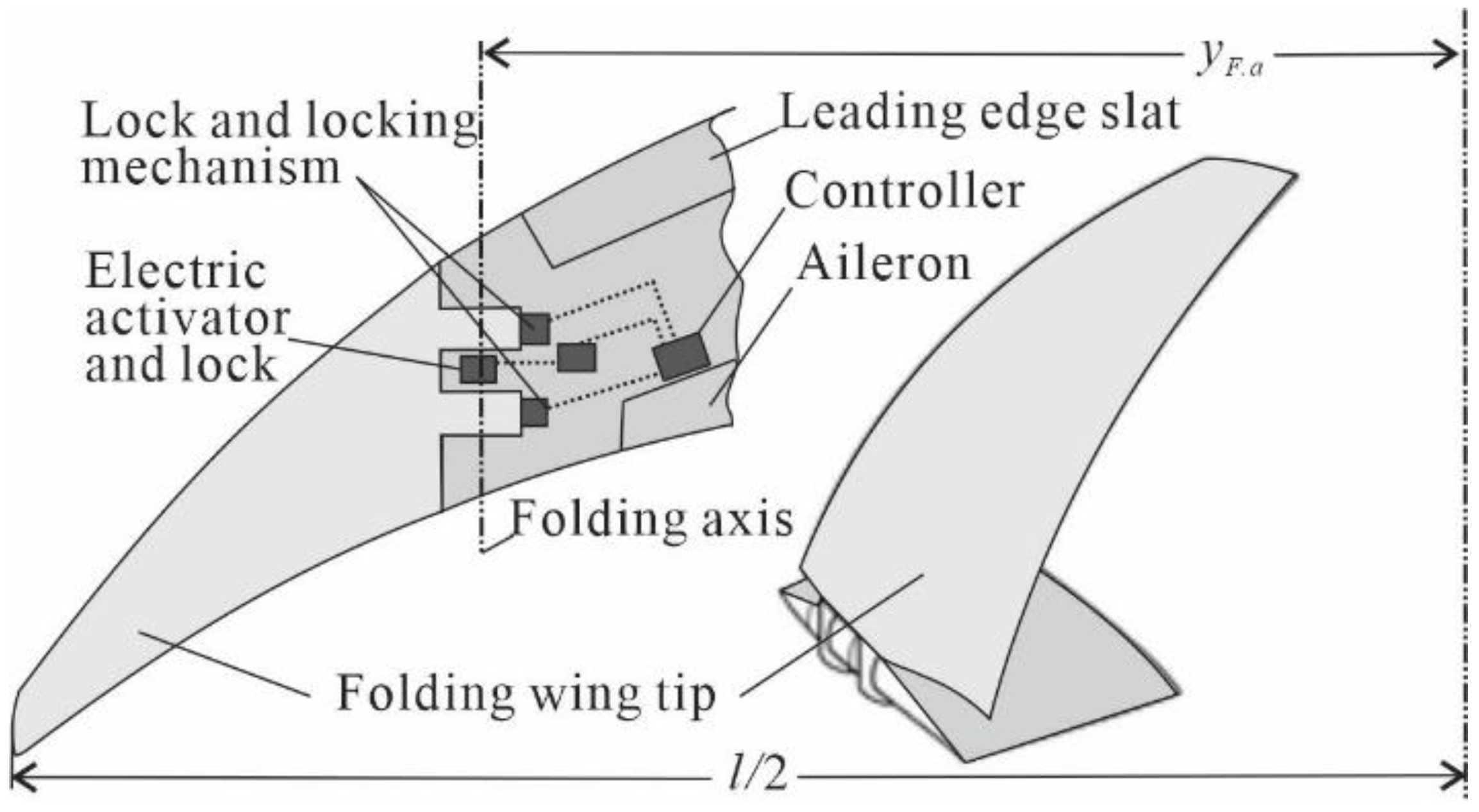
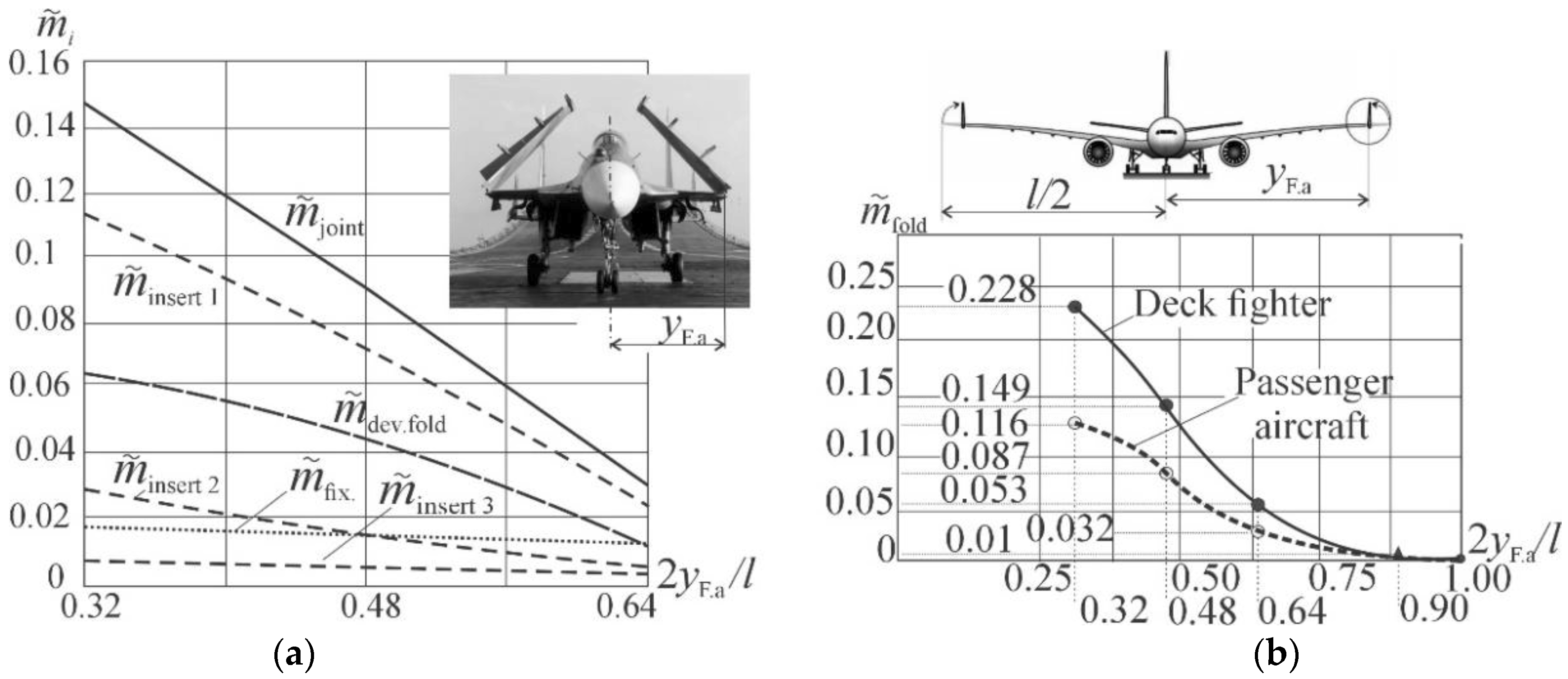
  • The approach to calculating the mass of the wing tip folding unit developed for deck-based aircraft was adapted for passenger aircraft.
  • The numerical fuel efficiency analysis was carried out using the proposed approach and the examples of Boeing and Airbus short-range commercial aircraft. It is shown that when transferring to wings with an aspect ratio of 11.5 made of composite materials, their fuel efficiency increases by 8–10% despite the use of folding wingtips.

Author Contributions

Conceptualization, A.K.; methodology, A.K. and D.T.; validation, A.K. and D.T.; investigation, A.K. and D.T.; writing—original draft preparation, A.K. and D.T.; writing—review and editing, D.T. All authors have read and agreed to the published version of the manuscript.

Funding

No external funding.

Institutional Review Board Statement

Not applicable.

Informed Consent Statement

Not applicable.

Data Availability Statement

Not applicable.

Conflicts of Interest

The authors declare no conflict of interest.

Nomenclature

CDaerodynamic drag coefficient,
C D   form aerodynamic drag coefficient of the form,
CD 0drag coefficient at zero lift force,
CDfusfuselage drag coefficient,
CDindinduced drag coefficient,
CKdimensionless factor characterizing the structure load-carrying scheme, and the nature of its loading,
CLlift force coefficient,
CL Kmaxlift force coefficient for maximum lift-to-drag ratio,
evspan efficiency factor,
c ¯ airfoil thickness ratio,
kfuel.smfuel.s/mfuel ratio,
keng.smeng.s/meng ratio,
lwingspan,
l fus   fuselage length,
lPreference size,
mDepmass dependent on mto,
mengengine mass,
meng.smass of the power plant,
mfuelfuel mass,
mfuel.sfuel system mass,
mIndmass independent on mto,
mpayloadpayload mass,
mstrmass of the structure,
mtargettarget mass,
mtomaximum takeoff mass,
mwing, mfus, mtail, mlgmass of structure units: wing, fuselage, tail and landing gear,
m ¯ i = m i / m to mass fraction from m to ,
m ˜ i = m i / m wing mass fraction from m wing ,
n calc load factor,
Preference load,
pspecific wing load,
Sarea of the wing,
y MAC distance from the plane of symmetry of the aircraft to the mean aerodynamic chord,
φ the coefficient taking into account the nonstructural elements and deviation from the theoretical variant in favor of manufacturability,
λ area of the wing,
η taper ratio (the ratio of tip chord to root chord),
χ le ,   χ 0.25swept angle wing at leading edge and at 0.25 chord,
μ msensitivity factor of takeoff mass (SFM),
ρ structural material density,
σ Upermissible stress,
σ ¯ specific strength of the main structural material.

References

  1. ICAO. Assembly Resolution on International Aviation and Climate Change (A37-19). In Proceedings of the Thirty-Fifth Session of the UNFCCC Subsidiary Body for Scientific and Technological Advice (SBSTA35), Bonn, Germany, 6–16 June 2011. [Google Scholar]
  2. ICAO. Present and Future Aircraft Noise and Emissions Trends Working Paper A37-WP/26. 2010. Available online: https://www.icao.int/environmental-protection/37thAssembly/wp026_en.pdf (accessed on 31 March 2022).
  3. Menouni, A.; Kretov, A.; Zhijin, W. Assessment of the passenger aircraft mass and efficiency with a fuselage without portholes. IOP Publishing. J. Phys. Conf. Ser. 2021, 1780, 012011. [Google Scholar] [CrossRef]
  4. EASA. ICAO Aircraft Engine Emissions Databank. European Union Aviation Safety Agency. 2019. Available online: https://www.easa.europa.eu/easa-and-you/environment/icaoaircraft-engine-emissions-databank (accessed on 1 March 2022).
  5. Seymour, K.; Held, M.; Georges, G.; Boulouchos, K. Fuel Estimation in Air Transportation: Modeling global fuel consumption for commercial aviation. Transp. Res. Part D Transp. Environ. 2020, 88, 102528. [Google Scholar] [CrossRef]
  6. Kretov, A.S.; Glukhov, V.V. Alternative Fuel in Transport Aviation and Estimation of Its Application Efficiency. Russ. Aeronaut. 2021, 64, 365–375. [Google Scholar] [CrossRef]
  7. Bicera, Y.; Dincer, I. Life cycle evaluation of hydrogen and other potential fuels for aircraft. Int. J. Hydrog. Energy 2017, 42, 10722–10738. [Google Scholar] [CrossRef]
  8. Verstraete, D. Long range transport aircraft using hydrogen fuel. Int. J. Hydrog. Energy 2013, 38, 14824–14831. [Google Scholar] [CrossRef]
  9. Hileman, J.I.; Stratton, R.W. Alternative jet fuel feasibility. Transp. Policy 2014, 34, 52–62. [Google Scholar] [CrossRef]
  10. Torenbeek, E. Advanced Aircraft Design: Conceptual Design, Analysis, and Optimization of Subsonic Civil Airplanes; John Wiley and Sons: Chichester, UK, 2013. [Google Scholar]
  11. Raymer, D.P. Aircraft Design: A Conceptual Approach, 6th ed.; AIAA: Reston, VA, USA, 2018. [Google Scholar]
  12. Poghosyan, M.A. Aircraft Design, 5th ed.; Innovative Engineering: Moscow, Russia, 2018. [Google Scholar]
  13. Val-Martinez, R.; Cuerno, C.; Perez, E.; Ghigliazza, H.H. Potential Effects of Blended Wing Bodies on the Air Transportation System. J. Aircr. 2010, 47, 1599–1604. [Google Scholar] [CrossRef]
  14. Chen, Z.; Zhang, M.; Chen, Y.; Sang, W.; Tan, Z.; Li, D.; Zhang, B. Assessment on Critical Technologies for Conceptual Design of Blended-Wing-Body Civil Aircraft. Chin. J. Aeronaut. 2019, 32, 1797–1827. [Google Scholar] [CrossRef]
  15. Okonkwo, P.; Smith, H. Review of Evolving Trends in Blended Wing Body Aircraft Design. Prog. Aerosp. Sci. 2016, 82, 1–23. [Google Scholar] [CrossRef]
  16. Udin, S.V.; Anderson, W.J. Wing mass formula for twin fuselage aircraft. J. Aircr. 1992, 29, 907–914. [Google Scholar] [CrossRef] [Green Version]
  17. Vedernikov, Y.V.; Chepiga, V.E.; Maslakov, V.P.; Kuklev, E.A.; Gusev, V.G. Configuration of the medium-haul twin-fuselage passenger aircraft. Int. J. Appl. Eng. Res. 2017, 12, 414–421. [Google Scholar]
  18. Ma, Y.; Elham, A. Twin-fuselage configuration for improving fuel efficiency of passenger aircraft. Aerosp. Sci. Technol. 2021, 118, 107000. [Google Scholar] [CrossRef]
  19. Kretov, A.S.; Glukhov, V.V. Application of Integrated Layout for “Cryogenic” Transport Category Aircraft. Russ. Aeronaut. 2022, 65, 10–24. [Google Scholar]
  20. Brushgens, G.S. Aerodynamic and Dynamic of Long-Haul Aircraft; TsAGI: Moscow, Russia, 1995. [Google Scholar]
  21. Riabkov, V.I.; Tiniakov, D.V. The method of forming the geometric parameters of lifting surfaces of aircraft transport category based on particular criteria and integral indicators of their effectiveness. J. Open Inf. Comput. Integr. Technol. Sci. Natl. Aerosp. Univ. 2011, 52, 41–48. [Google Scholar]
  22. Tiniakov, D.V. Integrated generation of the lift system surfaces geometric parameters on the preliminary designing stage of transport category airplanes. J. Open Inf. Comput. Integr. Technol. Sci. Natl. Aerosp. Univ. 2012, 53, 27–35. [Google Scholar]
  23. All the World’s Aircraft. Jane’s Publishing. Available online: https://janes.migavia.com (accessed on 11 July 2022).
  24. Boeing. Available online: https://www.boeing.com/777x/reveal/twitter-922798339946622976/ (accessed on 11 July 2022).
  25. Ballhays, W.F. Clear design thinking using the aircraft growth factor. In Proceedings of the 14th National Conference, Society of Aviation Weight Engineers, Fort Worth, TX, USA, 2–5 May 1955. [Google Scholar]
  26. Politkovsky, V.I.; Badyagin, A.A. On the Coefficient of Increasing the Launch Mass of the Aircraft. Izv.Vuz. Av. Tekhnika 1966, 9, 161–164. [Google Scholar]
  27. Ross, H. Effect of the Location of a Fixed Weight Penalty on the Aircraft Growth Factor. In Proceedings of the Social Aeronautic 28th Annual Conference, San Francisco, CA, USA, 5–8 May 1969; p. 0796. [Google Scholar]
  28. Gogolin, V.P. Determination of the Coefficient of Growth of Changes in Take-Off Weight During the Implementation of Changes in the Weight of the Structure. Vopr. Proekt. Letatel’nykh Appar. Tr. KAI 1973, 160, 11–15. [Google Scholar]
  29. Roskam, J. Airplane Design Part V: Component Weight Estimation; Roskam Aviation and Engineering Corp.: Ottawa, KS, USA, 1985. [Google Scholar]
  30. Hays, A.P. Zen and the art of airplane sizing. SAE Int. Paper 931255 1993, 102, 136–140. [Google Scholar] [CrossRef]
  31. Scholz, D. Understanding the aircraft mass growth and reduction factor. In Proceedings of the 15th European Workshop on Aircraft Design Education (EWADE 2020) and Research and Education in Aircraft Design (READ 2020), Warsaw, Poland, 21–23 October 2020; Available online: www.fzt.haw-hamburg.de/pers/Scholz/arbeiten/TextCheemaProject.pdf (accessed on 31 March 2022).
  32. Kretov, A. Sensitivity factors of aircraft mass for the conceptual design. J. Aircr. Eng. Aerosp. Technol. 2021, 93, 1470–1477. [Google Scholar] [CrossRef]
  33. Kowalski, M.; Goraj, Z.J.; Goliszek, B. The use of FEA and semi-empirical equations for weight estimation of a passenger aircraft. Aircr. Eng. Aerosp. Technol. 2021, 93, 1412–1420. [Google Scholar] [CrossRef]
  34. Dababneh, O.; Kipouros, T. A Review of Aircraft Wing Mass Estimation Methods. Aerosp. Sci. Technol. 2018, 72, 256–266. [Google Scholar] [CrossRef]
  35. Dorbath, F.; Gaida, U. Large Civil Jet Transport (MTOM > 40 t)—Statistical Mass Estimation. Luftfahrttechnisches Handbuch (LTH), 2013. Available online: https://www.lth-online.de/ueber-das-lth-informationen/lth-ausgabe.html (accessed on 31 March 2022).
  36. Kundu, A.K. Aircraft Design; Cambridge University Press: Cambridge, UK, 2010. [Google Scholar]
  37. Komarov, V.A. Mass analysis of aircraft structures: Theoretical foundations. J. Flight 2000, 1, 31–39. [Google Scholar]
  38. Komarov, V.A.; Weisshaar, T.A. New Approach to Improving the Aircraft Structural Design Process. J. Aircr. 2002, 39, 227–233. [Google Scholar] [CrossRef]
  39. Komarov, V.A.; Boldyrev, A.V.; Kuznetsov, A.S.; Lapteva, M.Y. Aircraft design using a variable density model. Aircr. Eng. Aerosp. Technol. 2012, 84, 162–171. [Google Scholar] [CrossRef]
  40. Komarov, V.A. Dimensionless criterion of the excellence of the power structures. J. Izv. Russ. Acad. Sci. Solid Mech. 2018, 4, 34–47. [Google Scholar]
  41. Kretov, A.S.; Shataev, P.A. Preliminary Assessment of the Mass of the Aircraft Fuselage as a Result of the Transition to Composite Materials. J. Russ. Aeronaut. 2020, 63, 386–396. [Google Scholar] [CrossRef]
  42. Awiation Week. Available online: https://aviationweek.com/commercial-aviation/boeing-777x-prototype-wingtip-tests-begin (accessed on 1 March 2022).
  43. Yarygina, M.V.; Popov, Y. Development of the weight formula for a folding wing. Russ. Aeronaut. 2012, 55, 120–126. [Google Scholar] [CrossRef]
  44. Mrazova, M. Future directions of fuel efficiency in aviation industry. INCAS Bull. 2013, 5, 71–86. [Google Scholar]
  45. Aircraft Technology Roadmap to 2050, IATA. Available online: https://www.iata.org/contentassets/8d19e716636a47c184e7221c77563c93/Technology-roadmap-2050.pdf (accessed on 1 March 2022).
  46. 777-200LR/-300ER/-Freighter; Airplane Characteristics for Airport Planning. Boeing: Arlington, VA, USA, 2015.
  47. 777-9; Airplane Characteristics for Airport Planning. Boeing: Arlington, VA, USA, 2018.
  48. Modern Airliners. Available online: https://modernairliners.com/boeing-777/boeing-777-specs/ (accessed on 1 March 2022).
  49. 737 MAX; Airplane Characteristics for Airport Planning. Boeing: Arlington, VA, USA, 2022.
  50. A320; Aircraft Characteristics. Airport and Maintenance Planning. Airbus: Blagnac, France, 2015.
  51. Kretov, A.; Tiniakov, D. Evaluation of Wing Structures at the Conceptual Stage of Transport Category Aircraft Project. Aviation 2022. accepted for publication. [Google Scholar]
Figure 1. Dynamics of aviation fuel cost change (Source: S&P Global, Refinitiv Eikon).
Aerospace 09 00497 g001
Figure 2. Existing and prospective aircraft with the same range and passenger capacity, but with greater fuel efficiency: (a) Boeing 747 and mixed wing-fuselage aircraft [19]; (b) A320neo and its two-fuselage counterpart [18].
Aerospace 09 00497 g002
Figure 3. Evolutionary aircraft wingspans and categories of airports and aircraft [23]. * For the Boeing 777X aircraft, two wingspans are shown: “ground” and “flight”.
Aerospace 09 00497 g003
Figure 4. Deflectable wingtips of the Boeing 777X [20,24].
Aerospace 09 00497 g004
Figure 5. The layout of the wingtip folding system [42].
Aerospace 09 00497 g005
Figure 6. Mass fractions of elements of the device for folding along the wingspan of the torsion-box load-carrying layout: (a) for the deck-based fighter [43]; (b) a mass fraction of the whole folding device for the fighter and passenger aircraft wing.
Aerospace 09 00497 g006
Figure 7. Dependence of cruise flight fuel mass fraction m ˜ f u e l   c r versus flight range: 1—Yak-40 with flight range 1000 km; 2—Tu-134 with flight range 2100 km; 3—Tu-154M with flight range 3900 km; 4—Airbus A320-200 with flight range 6100 km; 5—Airbus A310-300 with flight range 6500 km; 6—Boeing 777-200 with flight range 13,000 km; 7—Boeing 747-400 and Airbus A340-300 with flight range 13,500 km.
Aerospace 09 00497 g007
Table 1. Dependence of changes in CD ind on wing aspect ratio for Boeing 777 aircraft family.
ParametersS, m2l, m χ le , ° λ C D   ind C D  
Boeing-777-300ER427.864.8349.820.013370.02782
Boeing-777-9466.871.7630110.010350.02416
Table 2. Dependence of changes in CDind and CD on wing aspect ratio for Boeing 737Max 8 and Airbus A320Neo.
Parameterslflight, mlground, mS, m2 χ le , ° λhwinglet, m C D   ind C D   Δ C D   , %
Boeing-737-Max 8 (Base)35.935.912727102.920.0089740.0255
Boeing-737New
with new Aspect ratio
3935.91322711.50.0072820.0236–7.4
Airbus A320Neo (Base)35.835.81232710.52.430.008610.0235
Airbus A320New
with new Aspect ratio
3935.81322711.50.007520.0225–4.3
Table 3. Characteristics of masses for Boeing 737Max 8 and Airbus A320Neo and theirnew variants.
Parameters m to ,   t (Base) m fuel ,   t (Base) m wing ,   t by (13) m wing ,   t by (18) Δ m wing   λ   0   t Δ m wing   CM   0   t Δ m wing   fold   0 t Δ m fuel   Δ C D   0   t , by (23) μ m Δ m to ,   t , by (7) Δ m fuel ,   t by (11) Δ m fuel c r , %
by Figure 7
Δ m fuel %
Boeing-737-Max8 (Base)82.116.28.271.91 *
Boeing-737New9.585.841.31–3.740.1–1.2 –6.6–2.18–7.5–10.7
Airbus A320 Neo (Base)7818.97.961.85 *
Airbus A320New9.175.541.21–3.630.1–0.81 –5.8–1.9–5.7–8.15
* SFM values for Boeing-737 μ m = 1.91 and for Airbus A320 μ m = 1.85 were obtained in the research [51].
Publisher’s Note: MDPI stays neutral with regard to jurisdictional claims in published maps and institutional affiliations.

