An Application of a Magnetic Impulse for the Bending of Metal Sheet Specimens
Abstract
:1. Introduction
- The design and the construction of an experimental device intended to be used for the forming of metal sheets by a magnetic impulse as an unconventional way of forming metal sheets.
- The results of an experimental work conducted by means of the designed experimental device and to evaluate the obtained results in detail. Emphasis is especially placed on determining the achieved bending angle of experimental specimens.
- Novelty in the field of the forming of metal sheets by means of an ecological and economical way, namely, by means of the magnetic impulse to bend metal sheets with smaller dimensions.
2. Design and Construction of an Experimental Device
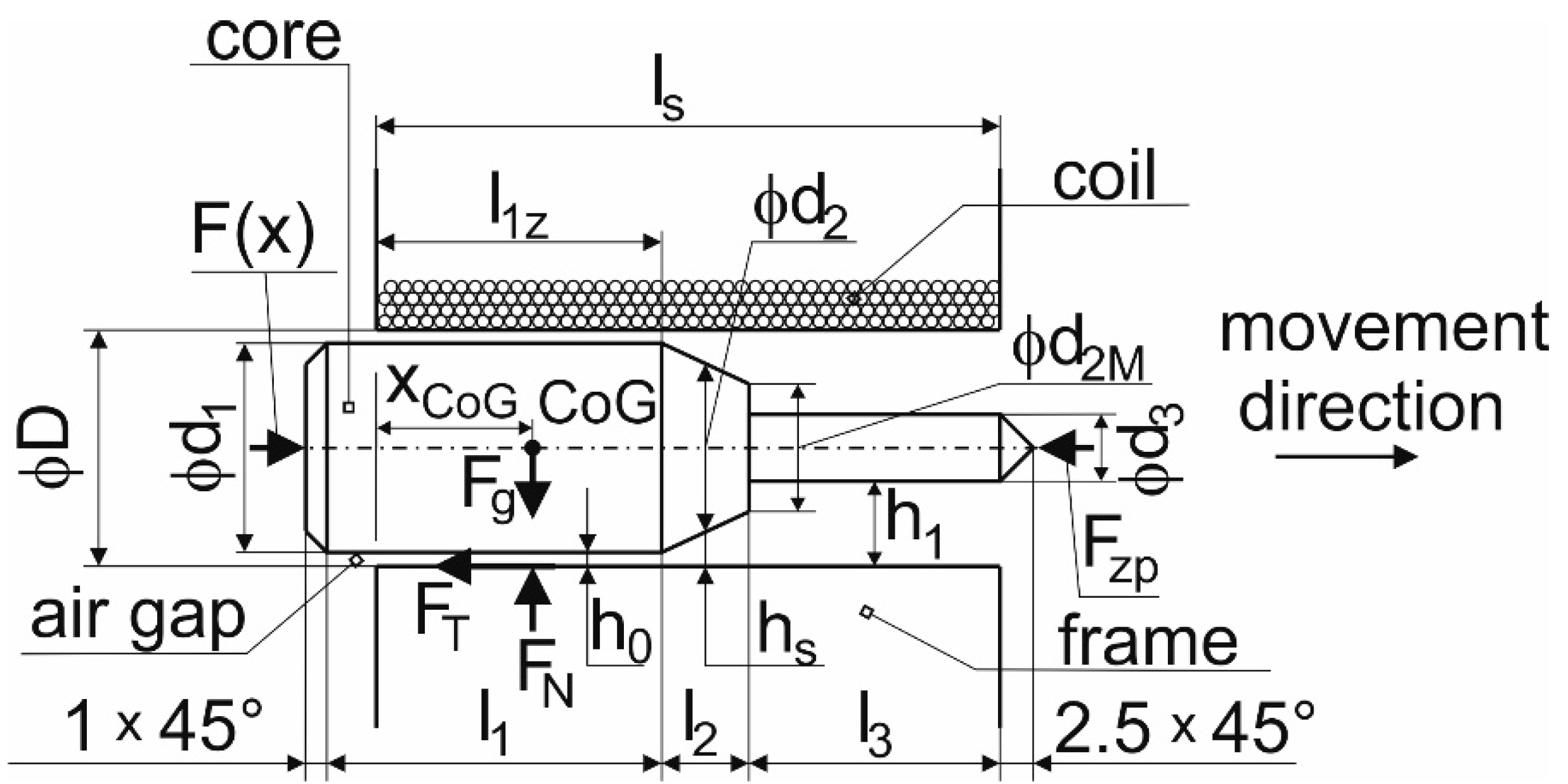
- F [N]—a quantified force moving the solenoid core;
- z [-]—the number of coil treads;
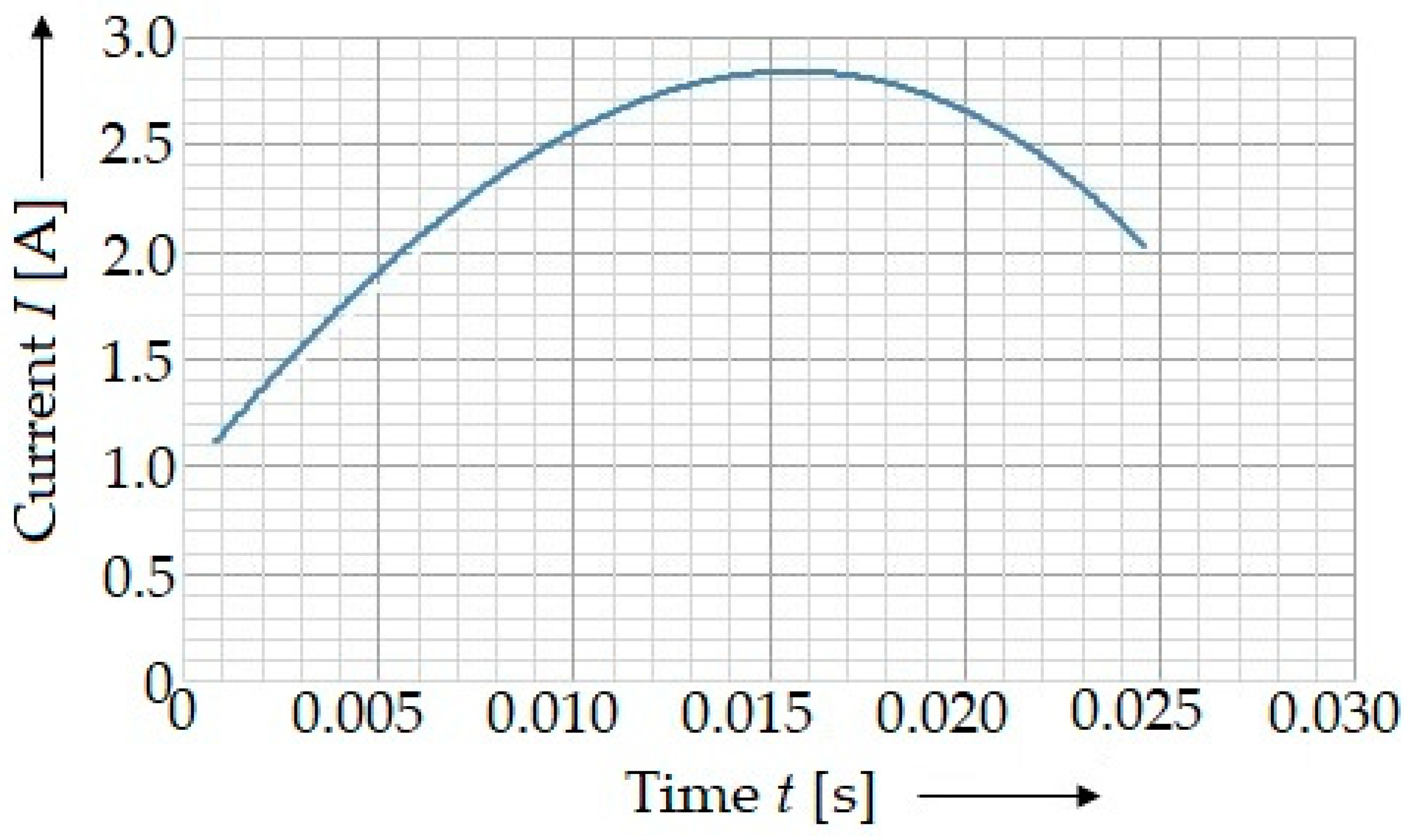
- I [A]—the current intensity in the solenoid;
- μ0 [N∙A−2]—the permeability of air, μ0 = 4∙π∙10−7;
- A [m2]—a cross-sectional area of the solenoid core;
- h [m]—an air-gap width between the core and coil of the solenoid;
- m [kg]—the weight of the solenoid core;
- g [m∙s−2]—the gravitational acceleration, g = 9.81 m s−2;
- A0 [m2]—a core area with the diameter d1, d1 = 17 mm, A0 = 2.2698 × 10⁻⁴ m2;
- As1 [m2]—a core area with the mean diameter of a cone d2s;
- A1 [m2]—a core area with the diameter d3;
- l1z [m]—an active length of the core with a diameter d1 in the solenoid at the beginning of a test;
- l2 [m]—an active length of the core with a diameter d2s in the solenoid during a test;
- l3 [m]—an active length of the core length with a diameter of d3 in the solenoid during a test;
- ls [m]—an active length of the solenoid coil;
- x [m]—a displacement of the core from the zero position at the beginning of the test in the direction of magnetism;
- h0 [m]—the minimal width of a gap between the core and the coil of the solenoid;
- hs1 [m]—the mean width of a width of the cone between the core and the coil of the solenoid;
- h1 [m]—the maximal width between the core and the coil of the solenoid;
- d2 [m]—the average diameter of a cone part;
- d2M [m]—the lower diameter of a cone part;
- d3 [m]—the diameter of the punch;
- d1 [m]—the diameter of the core;
- Fg [N]—the gravitational force of the core;
- FN [N]—the normal force due to the gravitational force Fg of the core;
- FT [N]—the tangential force due to the gravitational force Fg of the core and the friction;
- Fzp [N]—the resistance force of a specimen;
- D [m]—the internal diameter of the solenoid;
- CoG—the center of gravity of the core;
- xCoG [m]—the coordinate of the center of gravity of the core during its movement.
2.1. An Electrical Circuit for the Experimental Device
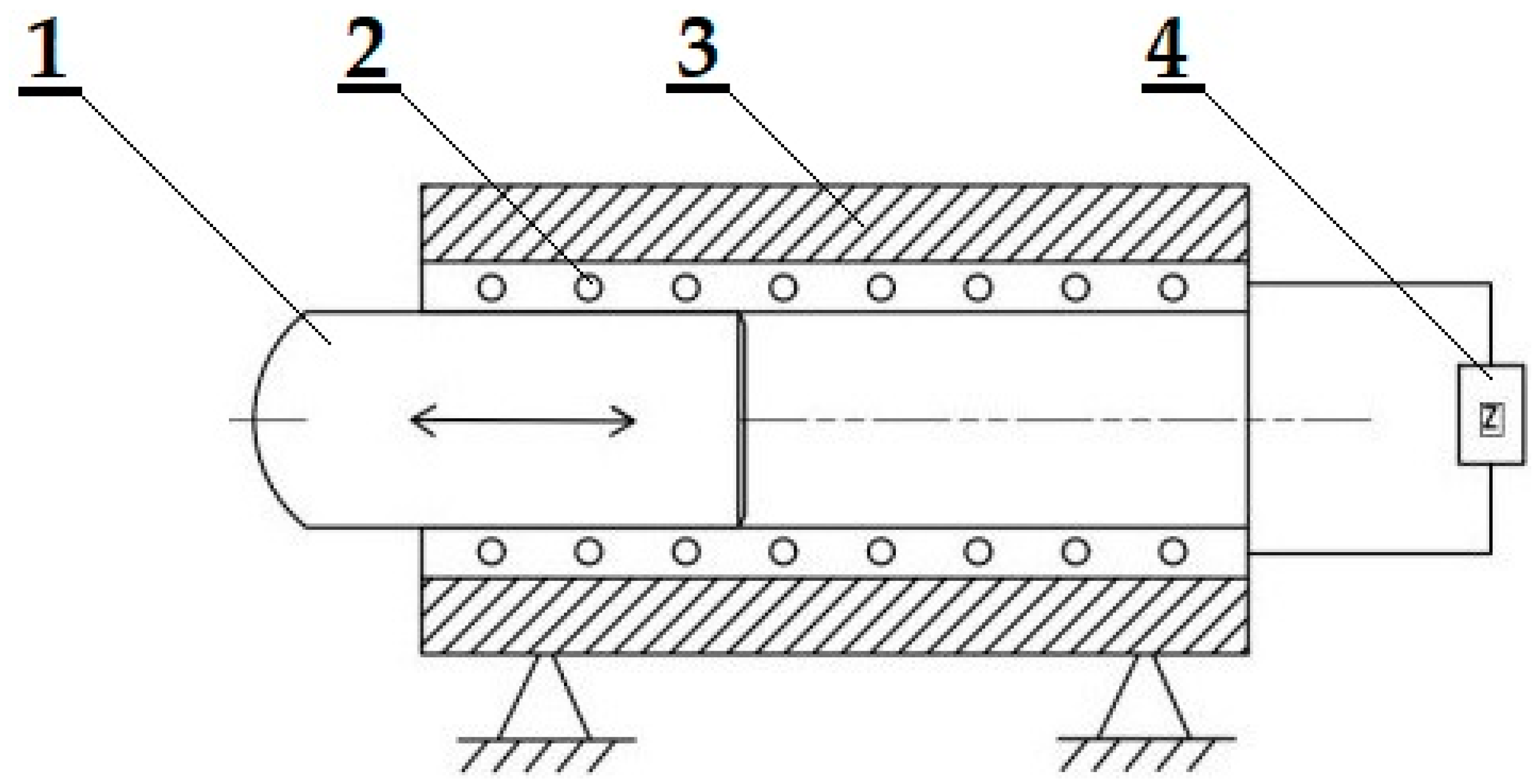
- Forming with a free core: the core moves in the horizontal direction in the solenoid cavity and, when it impacts the experimental specimens, its movement is stopped;
- A resilient core: the core is joined into a functional unit by means of a spring ensuring the displacement of the core after reaching the top dead center to the initial position.
2.2. A Movement of the Core in the Solenoid Cavity
3. A Mathematical Model of the Device Operation with a Stamp Using Experimentally Acquired Data
4. Experimental Tests
5. Results and Discussion
6. Conclusions
- Design of the original experimental-forming equipment;
- Verification of the suitability of the equipment in experimental conditions;
- Obtaining information about the course of the bending process and the results of the experiments.
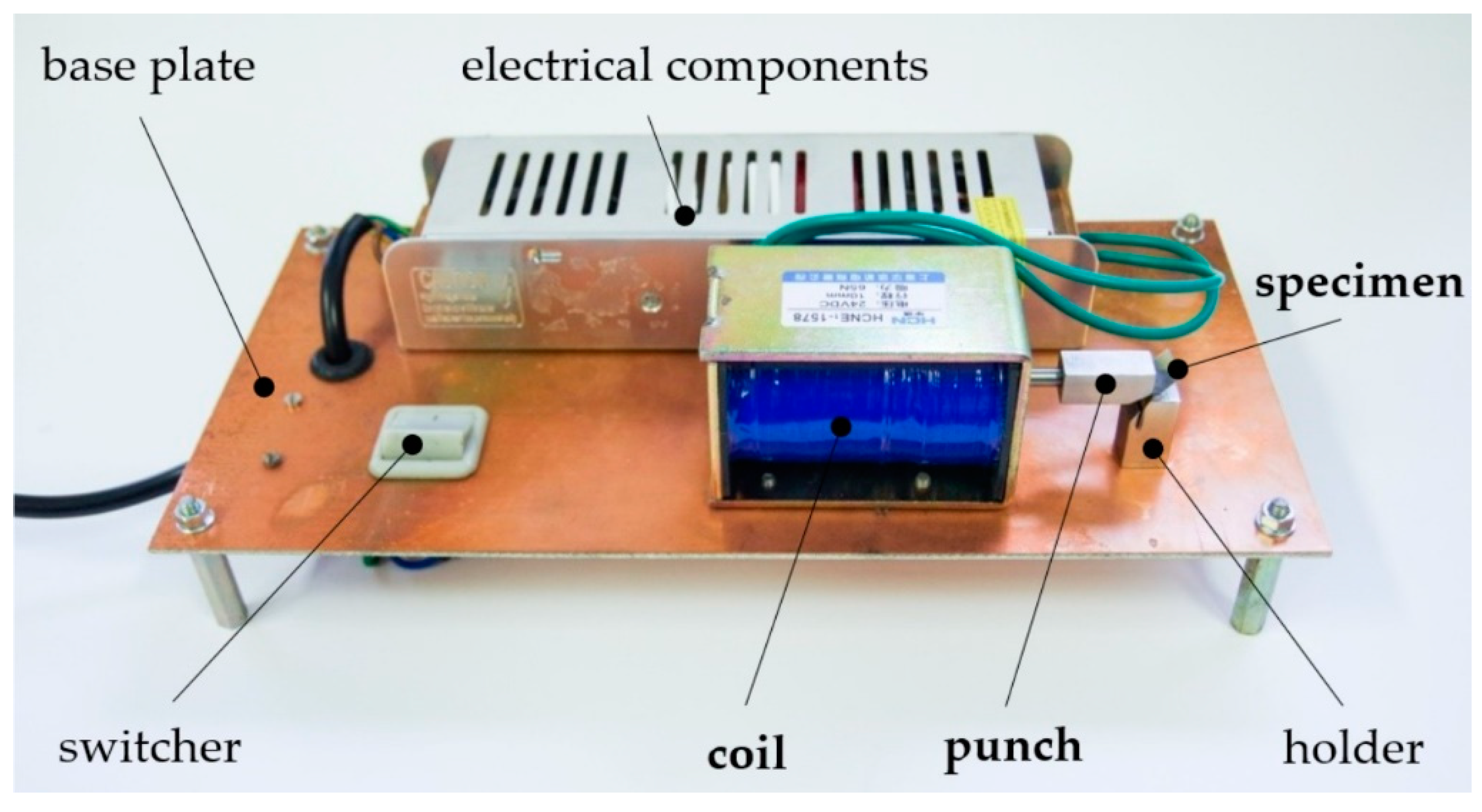
- The new experimental device for forming metal sheets was designed and manufactured.
- The working principle of the experimental device was described by the mathematical apparatus.
- The functionality of the experimental device was verified by experiments.
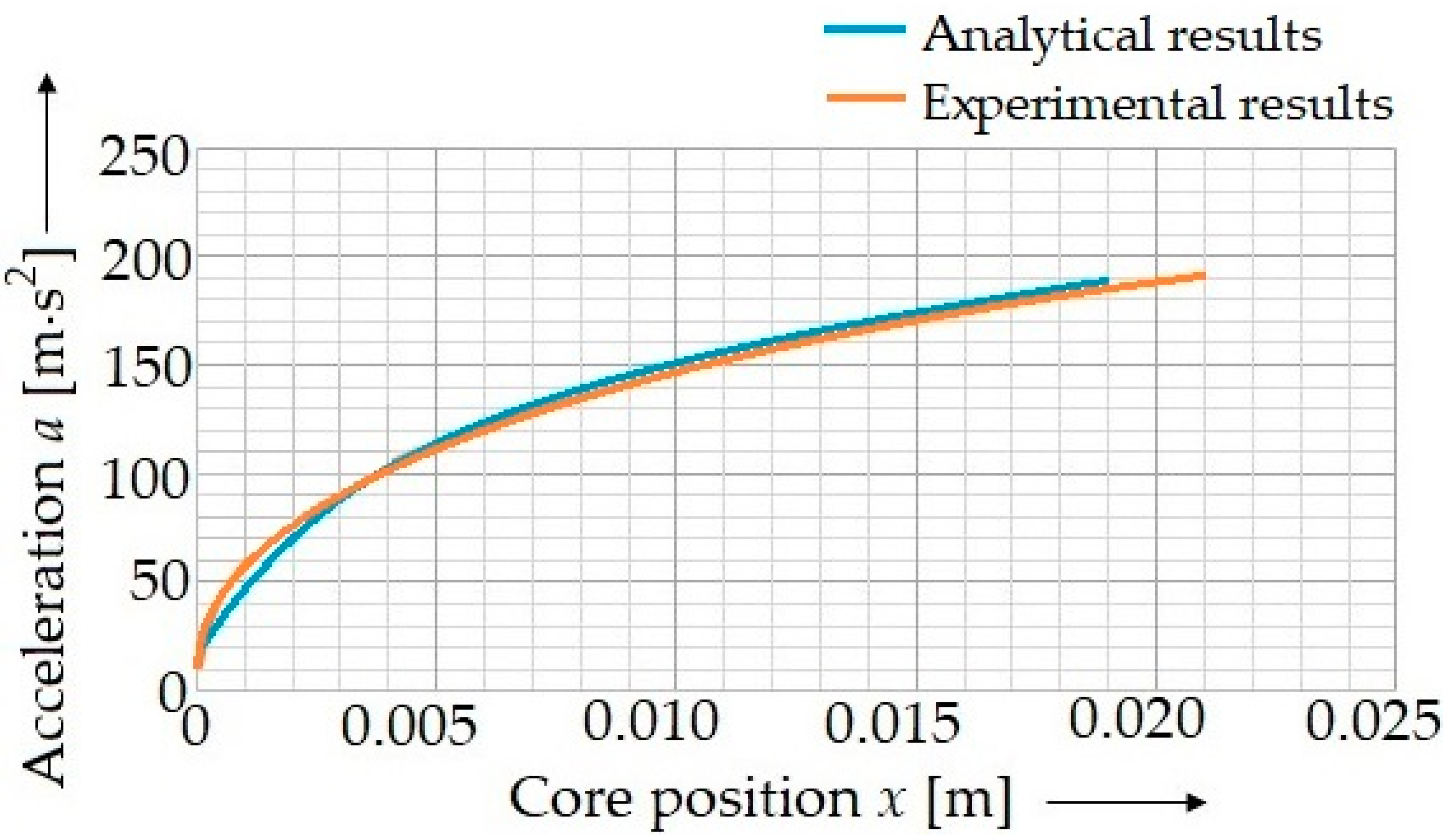
- The characteristics of the experimental device (focusing on the acceleration of the solenoid core) were determined by experimental tests and calculated by means of the mathematical apparatus. The results a high agreement with each other.
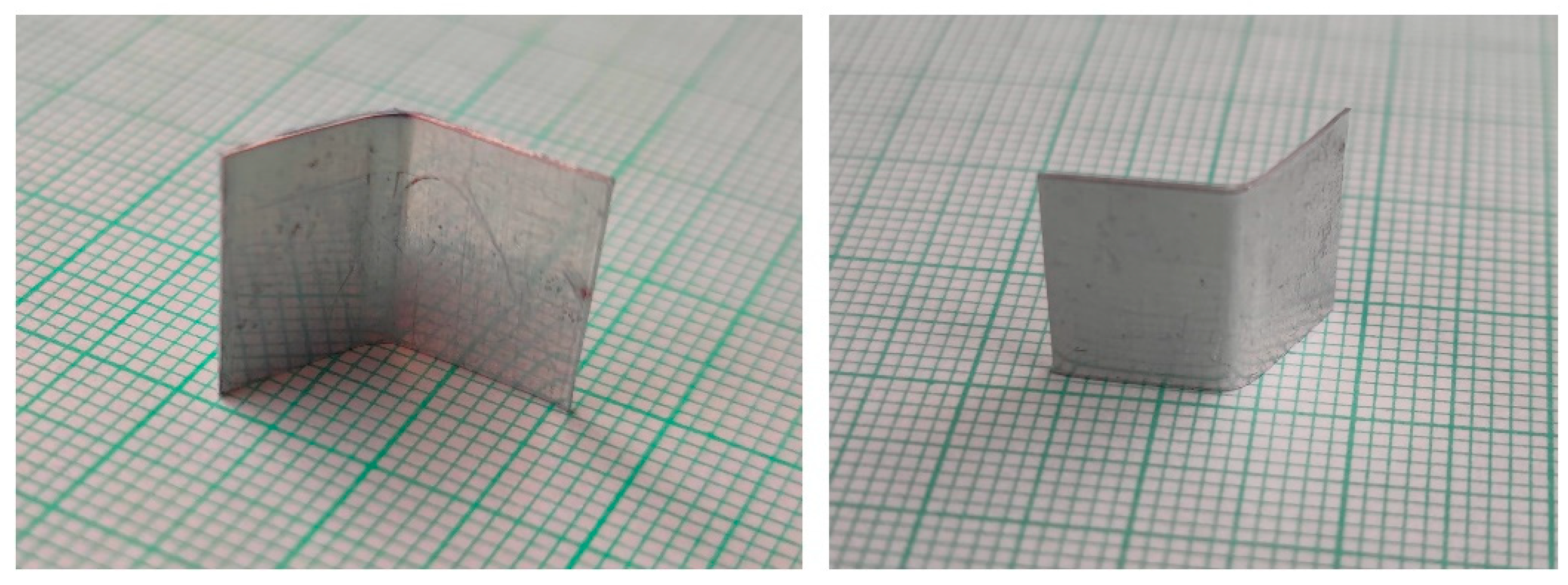
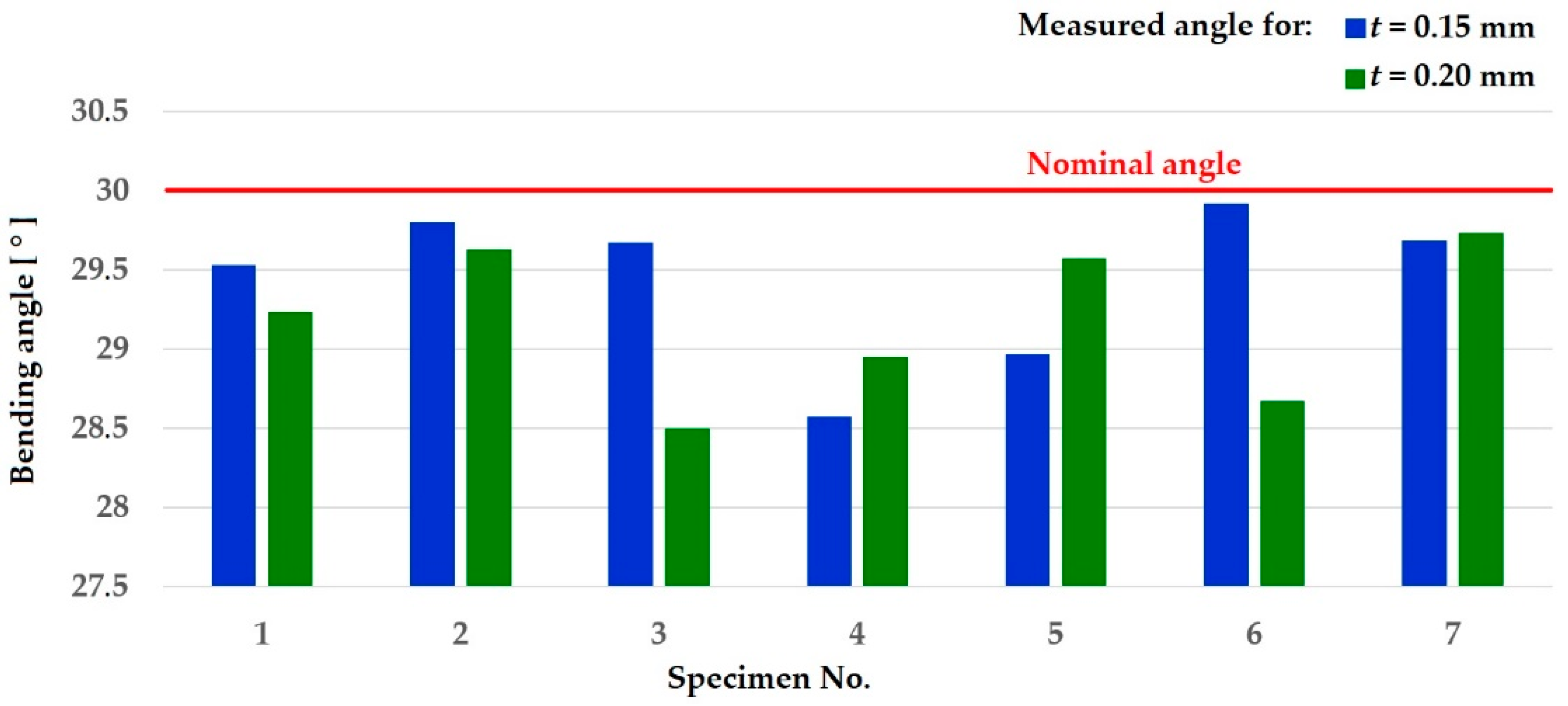
- The experimental device was used for the experiments to form metal sheets with the thicknesses of 0.15 mm and 0.20 mm. The results prove that the experimental device can be used for the bending of metal sheets.
- The proposed method can be applied to the practice of bending metal sheets in case of the construction of the device with the needed parameters.
- The forming of metal sheets can to contribute to the ecological and effective processes of forming metal sheets.
Author Contributions
Funding
Institutional Review Board Statement
Informed Consent Statement
Data Availability Statement
Acknowledgments
Conflicts of Interest
References
- Hai-Ping, Y.; Chin-Fang, L. Effects of coil length on tube compression in electromagnetic forming. Trans. Nonferrous Met. Soc. China 2007, 17, 1270–1275. [Google Scholar]
- Vanhunsel, P.; Van Wonterghem, M.; De Waele, W.; Faes, K. Groove design for form fit joints made by electromagnetic pulse clamping. Sustain. Constr. Des. 2011, 2, 432–441. [Google Scholar]
- Meng, Z.; Huang, S.; Hu, J.; Huang, W.; Xia, Z. Effects of process parameters on warm electromagnetic hybrid forming of magnesium alloy sheets. J. Mater. Process. Technol. 2011, 211, 863–867. [Google Scholar] [CrossRef]
- Golovashchenko, S.F. Electromagnetic Forming and Joining for Automotive Applications. Int. Conf. High Speed Form. 2006, 2, 201–206. [Google Scholar]
- Unger, J.; Stiemer, M.; Svendsen, B.; Blum, H. Multifield modeling of electromagnetic metal forming processes. J. Mater. Process. Technol. 2006, 177, 270–273. [Google Scholar] [CrossRef]
- Woodward, S.; Weddeling, C.; Daehn, G.; Psyk, V.; Carson, B.; Tekkaya, A.E. Production of low-volume aviation components using disposable electromagnetic actuators. J. Mater. Process. Technol. 2011, 211, 886–895. [Google Scholar] [CrossRef]
- Kamal, M.; Shang, J.; Cheng, V.; Hatkevich, S.; Daehn, G.S. Agile manufacturing of a micro- embossed case by a two-step electromagnetic forming process. J. Mater. Process. Technol. 2007, 190, 41–50. [Google Scholar] [CrossRef]
- Okoye, C.N.; Jiang, J.H.; Hu, Z.D. Application of electromagnetic-assisted stamping (EMAS) technique in incremental sheet metal forming. Int. J. Mach. Tools Manuf. 2006, 46, 1248–1252. [Google Scholar] [CrossRef]
- Krausel, V.; Schafer, R.; Engelbrecht, L. Gepulste electromagnetische Felder schneiden hochfest Bleche. Maschinenmarkt 2010, 4, 26–29. [Google Scholar]
- Kurka, P.; Landgrebe, D. Innovative Forming Technologies in Car Body Structures. In Proceedings of the 25th Anniversary International Conference on Metallurgy and Materials METAL 2016, Brno, Czech Republic, 25–27 May 2016. [Google Scholar]
- Bellitto, C.; Bauer, E.M.; Righini, G. On the crystal structures and magnetism of some hybrid organic-inorganic metal organophosphonates. Inorg. Chim. Acta 2008, 361, 3785–3799. [Google Scholar] [CrossRef]
- Cui, X.H.; Xiao, A.; Du, Z.H.; Yan, Z.Q.; Yu, H.L. Springback Reduction of L-Shaped Part Using Magnetic Pulse Forming. Metals 2020, 12, 390. [Google Scholar] [CrossRef] [Green Version]
- Kurlaev, N.V.; Matveev, K.A.; Ahmed Soliman, M.E.; Detinov, M.B. Forming the straight flange of a rib by pulsed-magnetic field pressure. In Proceedings of the 3rd International Conference on Advanced Technologies in Aerospace, Mechanical and Automation Engineering, Krasnoyarsk, Russia, 20–21 November 2020. [Google Scholar]
- Heidhoff, J.; Beckschwarte, B.; Riemer, O.; Schönemann, L.; Herrmann, M.; Schenck, C.; Kuhfuss, B. Electromagnetic embossing of optical microstructures with high aspect ratios in thin aluminum sheets. In Proceedings of the 24th International ESAFORM Conference on Material Forming, Virtual Conference, Liege, Belgium, 14–16 April 2021. [Google Scholar]
- Beckschwarte, B.; Herrmann, M.; Schenck, C.; Kuhfuss, B. Determination of plastic material properties of thin metal sheets under electromagnetic forming conditions. In Proceedings of the 24th International ESAFORM Conference on Material Forming, Virtual Conference, Liege, Belgium, 14–16 April 2021. [Google Scholar]
- Nescoromniy, S.V.; Strizhakov, E.L.; Rogozin, D.V. Research and Development of Tubular Products Magnetic Pulse Welding-Forming Technology for Space Engineering. In Proceedings of the 2nd International Conference on Industrial Engineering, ICIE 2016, Chelyabinsk, Russia, 19–20 May 2016. [Google Scholar]
- Ibrahim, A.D.; Hussein, H.M.A.; Ahmed, I.; Nasr, E.A.; Kamrani, A.; Abdelwahab, S.A. Computer-aided design of traditional jigs and fixtures. Appl. Sci. 2022, 12, 3. [Google Scholar] [CrossRef]
- Bergmann, B.; Denkena, B.; Beblein, S.; Picker, T. FE-Simulation based design of wear-optimized cutting edge roundings. J. Manuf. Mater. Process. 2021, 5, 126. [Google Scholar] [CrossRef]
- Li, Z.; Jiang, H.; Wang, M.; Jia, H.; Han, H.; Ma, P. Microstructure and Mechanical Properties of Al-Mg-Si Similar Alloy Laminates Produced by Accumulative Roll Bonding. Materials 2021, 14, 4200. [Google Scholar] [CrossRef] [PubMed]
- Beckschwarte, B.; Langstadtler, L.; Schenck, C.; Herrmann, M.; Kuhfuss, B. Numerical and Experimental Investigation of the Impact of the Electromagnetic Properties of the Die Materials in Electromagnetic Forming of Thin Sheet Metal. J. Manuf. Mater. Process. 2021, 5, 18. [Google Scholar] [CrossRef]
- Rezinkin, O.L.; Rezinkina, M.M.; Gryb, O.G.; Revutsky, V.I. Cold pressing of ferroelectric-ferromagnetic layered composites for nonlinear forming lines of high-voltage impulse generators. Funct. Mater. 2017, 24, 168–174. [Google Scholar] [CrossRef]
- Gabajová, G.; Furmannová, B.; Medvecká, I.; Grznár, P.; Krajčovič, M.; Furmann, R. Virtual training application by use of augmented and virtual reality under university technology enhanced learning in Slovakia. Sustainability 2019, 11, 6677. [Google Scholar] [CrossRef] [Green Version]
- Grznár, P.; Gregor, M.; Gašo, M.; Gabajová, G.; Schickerle, M.; Burganová, N. Dynamic simulation tool for planning and optimisation of supply process. Int. J. Simul. Model. 2021, 20, 441–452. [Google Scholar] [CrossRef]
- Moravec, J. Electromagnetic forming of thin-walled tubes. In Proceedings of the International Conference on Metallurgy and Materials METAL 2017, Brno, Czech Republic, 24–26 May 2017. [Google Scholar]
- Moravec, J. Unconventional method of forming circumferential rings on sheet metal parts. In Proceedings of the Anniversary International Conference on Metallurgy and Materials METAL 2018, Brno, Czech Republic, 23–25 May 2018. [Google Scholar]
- Moravec, J. Magnetic field application in area sheet metal forming. In Proceedings of the International Conference on Metallurgy and Materials METAL 2016, Brno, Czech Republic, 25–27 May 2016. [Google Scholar]
- Moravec, J. Electromagnetic Sheet Metal Forming, Elektromagnetische Blechumformung; University of Žilina: Žilina, Slovak Republic, 2019. [Google Scholar]
- Kapil, A.; Sharma, A. Magnetic pulse welding: An efficient and environmentally friendly multi-material joining technique. J. Clean. Prod. 2015, 100, 35–58. [Google Scholar] [CrossRef]
- Kapil, A.; Sharma, A. Coupled electromagnetic-structural simulation of magnetic pulse welding. In Advances in Material Forming and Joining, 1st ed.; Narayanan, R.G., Dixit, U.S., Eds.; Springer: New Delhi, India, 2015; pp. 255–272. [Google Scholar]
- Psyk, V.; Risch, D.; Kinsey, B.L.; Tekkaya, A.E.; Kleiner, M. Electromagnetic forming–A review. J. Mater. Process. Technol. 2011, 211, 787–829. [Google Scholar] [CrossRef]
- Schimpf, P. A detailed explanation of solenoid force. Int. J. Recent Trends Eng. Technol. 2013, 8, 7–14. [Google Scholar]




| Element | Si | Mn | S | Cr | Mo | Ni |
| Specimen No. 1, t = 0.15 mm | 0.94 | 1.29 | 0.026 | 17.0 | 0.52 | 6.57 |
| Specimen No. 2, t = 0.20 mm | 0.96 | 1.30 | 0.034 | 17.2 | 0.44 | 6.75 |
| Element | Cu | Nb | V | Pb | Fe | |
| Specimen No. 1, t = 0.15 mm | 0.34 | 0.01 | 0.06 | 0.02 | 73.7 | |
| Specimen No. 2, t = 0.20 mm | 0.21 | 0.016 | 0.10 | 0.029 | 72.9 |
| Specimen No. | Bending Angle (°) | Deviation from the Required Angle (°) | ||
|---|---|---|---|---|
| t = 0.15 mm | t = 0.20 mm | t = 0.15 mm | t = 0.20 mm | |
| 1 | 29°32′ | 29°14′ | 28′ | 46′ |
| 2 | 29°48′ | 29°38′ | 12′ | 12′ |
| 3 | 29°40′ | 28°30′ | 20′ | 1°30′ |
| 4 | 28°34′ | 28°57′ | 1°26′ | 1°3′ |
| 5 | 28°58′ | 2934′ | 1°2′ | 26′ |
| 6 | 29°55′ | 28°40′ | 5′ | 1°20′ |
| 7 | 29°41′ | 29°44′ | 19′ | 16′ |
Publisher’s Note: MDPI stays neutral with regard to jurisdictional claims in published maps and institutional affiliations. |
© 2022 by the authors. Licensee MDPI, Basel, Switzerland. This article is an open access article distributed under the terms and conditions of the Creative Commons Attribution (CC BY) license (https://creativecommons.org/licenses/by/4.0/).
Share and Cite
Moravec, J.; Blatnický, M.; Dižo, J. An Application of a Magnetic Impulse for the Bending of Metal Sheet Specimens. Materials 2022, 15, 3558. https://doi.org/10.3390/ma15103558
Moravec J, Blatnický M, Dižo J. An Application of a Magnetic Impulse for the Bending of Metal Sheet Specimens. Materials. 2022; 15(10):3558. https://doi.org/10.3390/ma15103558
Chicago/Turabian StyleMoravec, Ján, Miroslav Blatnický, and Ján Dižo. 2022. "An Application of a Magnetic Impulse for the Bending of Metal Sheet Specimens" Materials 15, no. 10: 3558. https://doi.org/10.3390/ma15103558
APA StyleMoravec, J., Blatnický, M., & Dižo, J. (2022). An Application of a Magnetic Impulse for the Bending of Metal Sheet Specimens. Materials, 15(10), 3558. https://doi.org/10.3390/ma15103558


