1. Introduction
Fiber-reinforced polymer plastics (FRPs) possess superior specific strengths and stiffness in comparison to other structural composites, such as metal or ceramic-reinforced composites. The relative ease of manufacturing, light weight, wide range of physical properties and high corrosion resistance make FRPs very desirable for several applications [
1,
2].
Compared to other structural fibers, carbon fibers are utilized when fatigue resistance, moderate strength and electrical conductivity are needed and when weight savings are crucial. Recently, nanofilament forms of carbon reinforcement, such as carbon nanotubes (CNTs) and carbon nanofibers [
3], have gained growing interest in the composites community, due to their attractive mechanical properties. However, researchers have attempted to incorporate CNTs in polymer matrices and have met limited success, due to the extreme difficulty in uniformly dispersing CNTs in polymeric matrices, because of the large surface area of CNTs [
4]. The high-aspect ratio CNTs tend to entangle and form agglomerates when dispersed into a viscous polymeric matrix. Sonication [
3] and calendaring [
5] have been employed extensively to mitigate this problem, but both techniques are not feasible beyond ~3.0 wt% CNT, due to the formation of aggregates [
6]. A combination of dispersion and extrusion techniques have been reported in the literature for producing CNT composites [
6] with a tailored microstructure, e.g., aligned CNTs. However, in both dispersion and extrusion techniques, producing uniform and well-dispersed CNT composites is difficult, due to the phase separation stemming from the stronger van der Waals interactions amongst the CNTs bundles compared with that between the CNTs and the polymer matrix [
7]. Furthermore, excessive sonication of CNTs toward better dispersion might result in breaking them into shorter tubes, thus reducing their aspect ratios [
8] and, consequently, negatively affecting their derived composite mechanical performance.
One viable alternative to prevent nanofilaments agglomeration is to anchor one end of the nanofilament to the substrate, thereby creating a stable multiscale structure. This approach can be implemented by physically growing the nanofilaments directly on the surface of the substrate (in this study, the substrate is micro-scale carbon fiber bundles). Carbon nanotubes have been grown on most substrates, such as silicon, silica and alumina [
9]. However, there are fewer reports discussing CNT growth on carbon materials; in particular, yarns and fabrics [
10]. Two challenges face CNT growth on carbon substrates, namely: (i) the transition metals that catalyze the CNTs growth can easily diffuse into the carbon substrates and; (ii) different phases of carbon materials are able to form on the graphite substrates, because the CNT growth conditions are identical to the graphite or diamond-like carbon growth [
11].
Recently, carbon nanofilaments were grown on carbon fibers, both polyacrylonitrile- (PAN) and pitch-based, by hot filament chemical vapor deposition (HFCVD) using H
2 and CH
4 as precursors [
12]. Nickel clusters were electrodeposited on the fiber surfaces to catalyze the growth, and uniform CNT coatings were obtained on both the PAN and pitch-based carbon fibers. Multi-walled CNTs with smooth walls and low impurity content were also grown on a carbon fiber cloth using plasma-enhanced chemical vapor deposition (PECVD) from a mixture of acetylene and ammonia [
13]. In this case, a cobalt colloid was utilized to achieve the good coverage of nanofibers on the carbon cloth. The main draw back to CNT growth via CVD is the damage induced on the carbon fiber surface due to the high-temperature synthesis (>750 °C) [
11,
12]. Qu
et al. [
14] reported a new method for the uniform deposition of CNTs on carbon fibers. However, this method requires processing at 1100 °C in the presence of oxygen, and such a high temperature is anticipated to severely damage the carbon fibers. One approach to circumvent the thermal damage due to the synthesis at elevated temperature environments is to utilize ceramic-based thermal barrier coatings, such as SiC or SiO
2.
In this study, carbon nano-filaments were grown utilizing a moderate temperature (
i.e., 550 °C) under atmospheric pressure. This atmospheric pressure process, derived from the process, graphitic structures by design (GSD) [
15,
16], is rapid, and the temperature is low enough (
i.e., 550 °C) to avoid severe structural damage to the substrate macroscale carbon fibers; and, the process is inexpensive and readily scalable. The GSD process does not utilize any toxic hydrocarbons or catalysts (e.g., xylene and metallocene) unlike CCVD [
17]. Finally, GSD could offer the opportunity to place CNTs in pre-designated locations (where the catalyst is pre-deposited), whereas utilizing the CCVD technique, CNTs grow everywhere. This investigation sheds some light on the effect of the growth technique on the quasistatic mechanical properties of FRPs made out of a hybrid reinforcement that utilizes carbon nanofilaments grown on the surface of carbon fibers.
2. Results and Discussion
Based on previous experiences, the nickel film should be fragmented into particles to grow carbon nanofilaments via GSD; otherwise, it might lead to the growth of either graphene of graphite [
18]. A reduction step at 550 °C under a N
2-H
2 environment was carried out for 2 h under atmospheric pressure to fragment the nickel film into nanometer-sized particles and to remove any nickel oxides (
Figure 1a). These particles are retained on the tips of the nanofilaments grown via GSD, as shown in
Figure 1b.
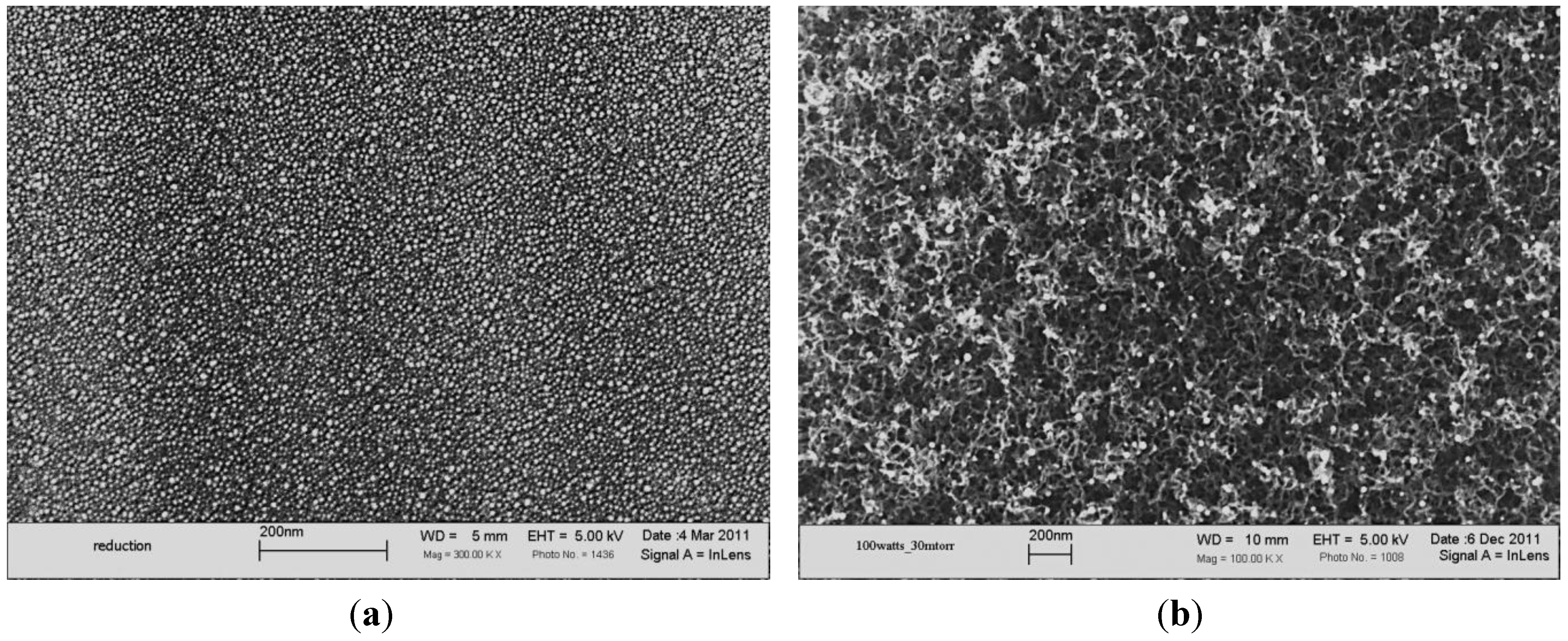
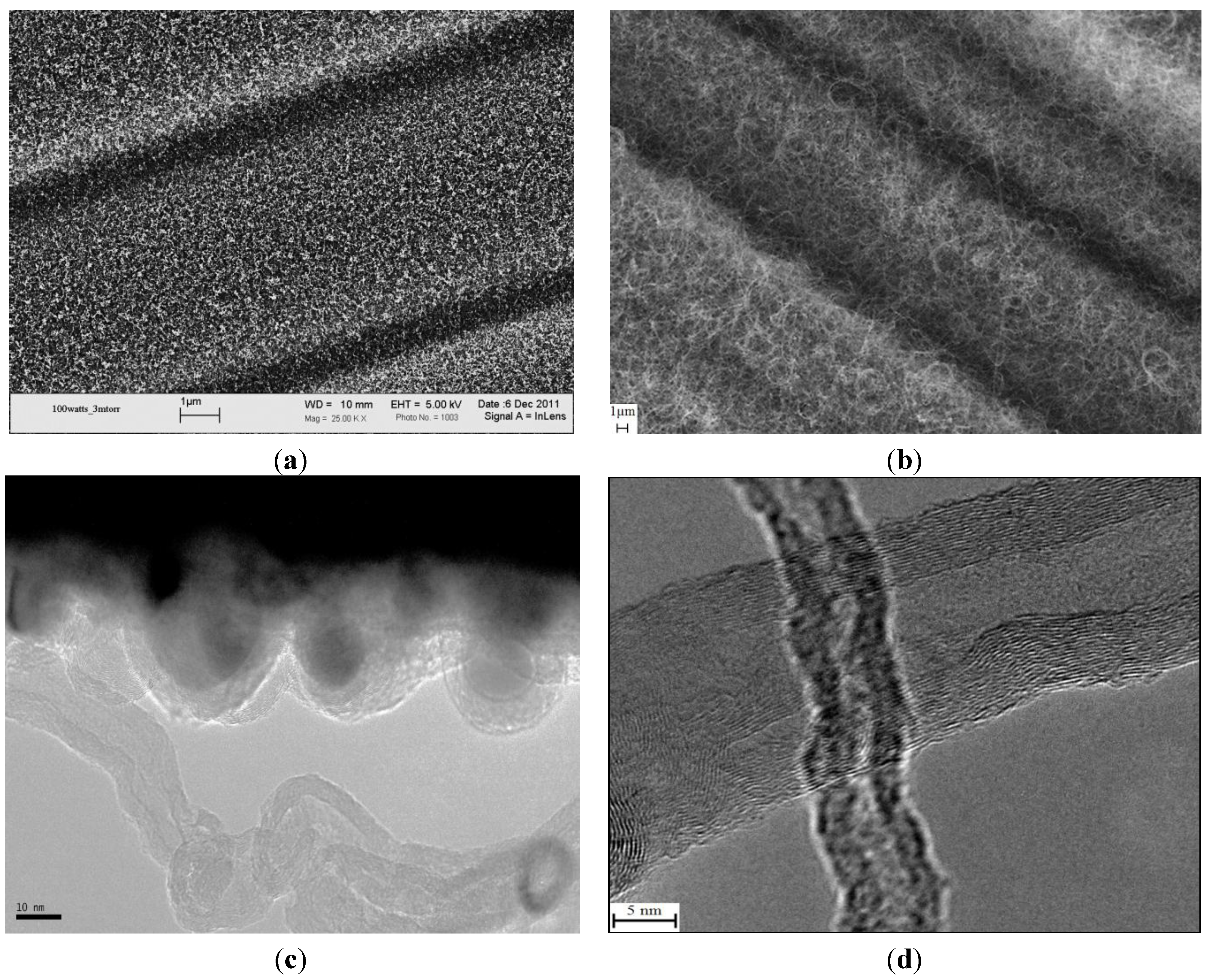
The SEM micrographs in
Figure 2a,b exhibit a uniform growth of CNTs utilizing GSD and CCVD techniques, respectively, on the surface of PAN-based carbon fibers, where the nickel catalytic particles were deposited (for the case of GSD). Both fibers were precoated with 75 nm-thick films of SiO
2, in anticipation of better thermal shielding against the synthesis temperature. The morphologies of the grown nanofilaments are shown in the TEM micrographs (
Figure 2c, d). The GSD-synthesized nanofilament does not exhibit well-defined walls and possesses a diameter of less than 20 nm, whereas the CCVD yielded better defined multiwall CNTs (MWCNTs) with variable diameters.
Since the samples comprising the surface-grown nanofilaments were exposed to elevated temperatures (
i.e., 550–680 °C), reference samples of raw fabric and SiO
2 sputter-coated fabric were exposed to an identical thermal environment similar to GSD (except for prohibiting the growth without the flowing of hydrocarbon gas) for later comparison. These samples are referred to as “heat treated” throughout this study. The Raman spectra were measured for the raw PAN-based carbon fabric, SiO
2 sputter-coated fabric, heat-treated fabric, heat-treated SiO
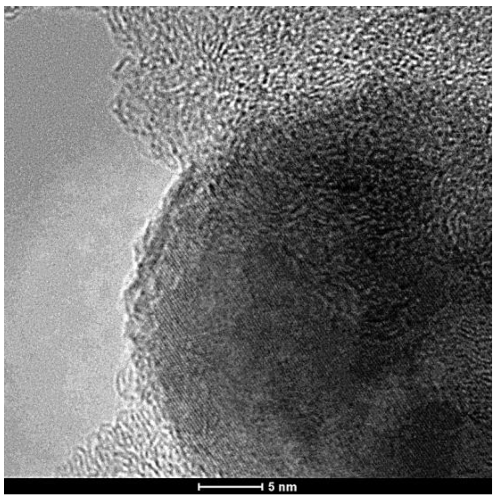
2 sputter-coated fabric and samples with CNTs grown on their surfaces via the GSD and CCVD techniques. While the as-sputtered nickel thin film is amorphous, evidenced by the ordered fringe patterns of
Figure 3, upon fragmentation and reduction, the nickel particles become crystalline.
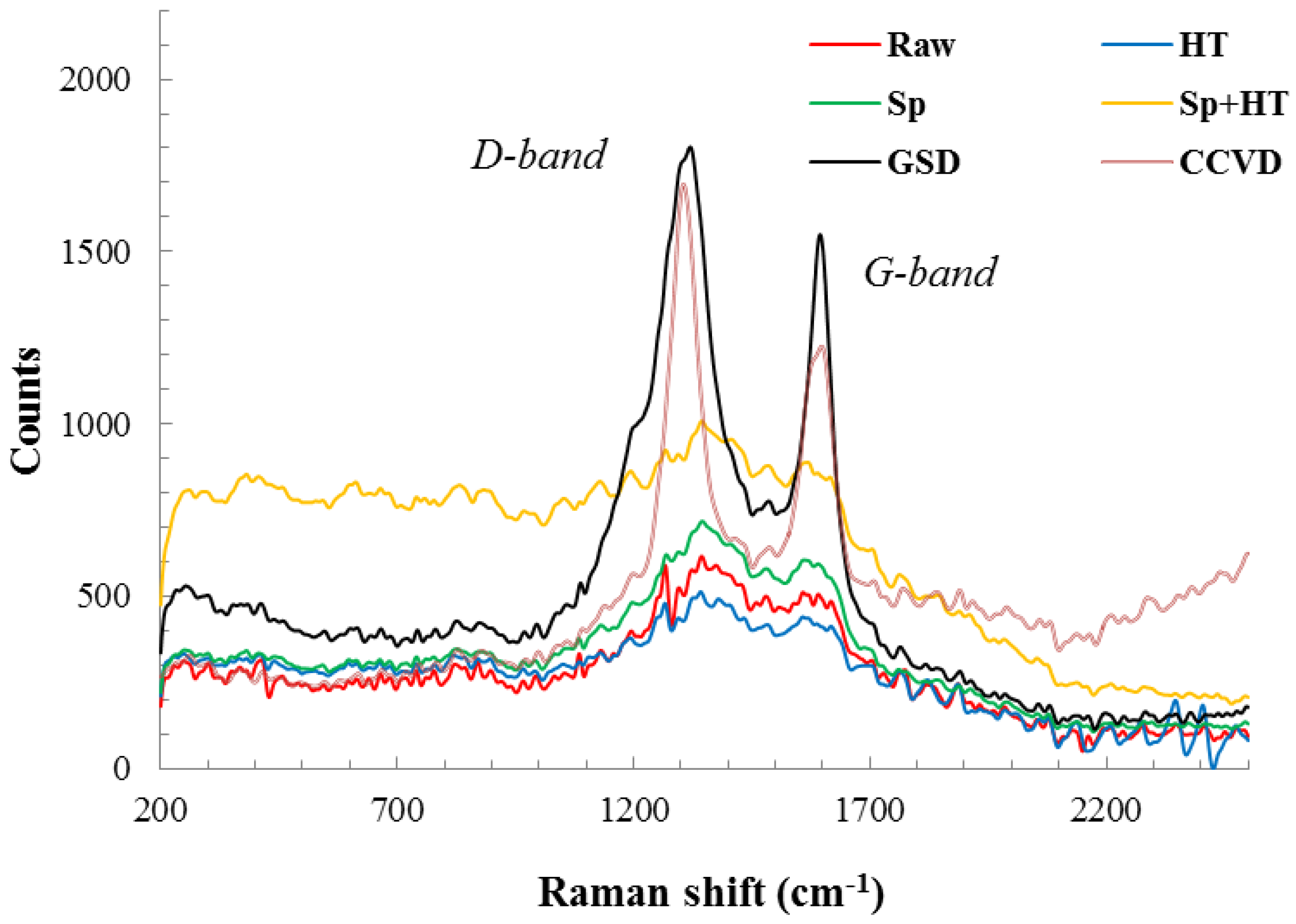
For carbonaceous materials, the Raman spectra exhibit two distinct bands. The disorder induced D band at 1354.7 cm
−1 in the MWCNT spectra and between 1330 and 1390 cm
−1 in single wall carbon nanotubes (SWCNT) The tangential mode G band, related to the ordered graphitic structure, appears at 1581.2 cm
−1 for the MWCNT and between 1595 and 1605 cm
−1 for the SWCNT [
19].
Raman peaks (
Figure 4) for all of the samples without nanofilament growth are very weak, regardless of the prior surface treatment, and do not exhibit the presence of a crystalline form of carbon. The raw carbon fibers did not display significant peaks. It is well known that PAN-based carbon fibers do not exhibit the G band (unlike graphitic pitch-based fibers); rather, they exhibit the turbostratic appearance of the D line, which corresponds to the structural disorder caused by the existence of the sp
3 bonds [
20].
Sputtering the fibers with nickel and SiO
2 films assisted in contrasting the G band for the fibers. Furthermore, heat treating of the samples with the deposited films made the D and G bands more pronounced. The CNTs grown on the surfaces of the PAN-based carbon fiber fabric via GSD or CCVD demonstrate the D-band center value at 1350 cm
−1 and the G-band at 1580 cm
−1, respectively; in good agreement with those of the Raman spectra of MWCNTs. Although these peaks are also observed for graphite [
21], it is evident from the SEM and TEM micrographs of the nanofilaments that the Raman peaks cannot be from graphite.
Figure 1.
SEM micrographs for (a) nickel particles formed after the reduction process under N2-H2 at 550 °C; (b) nanofilaments grown utilizing the graphitic structures by design (GSD) technique with nickel particles attached to their tips.
Figure 1.
SEM micrographs for (a) nickel particles formed after the reduction process under N2-H2 at 550 °C; (b) nanofilaments grown utilizing the graphitic structures by design (GSD) technique with nickel particles attached to their tips.
Figure 2.
The SEM micrograph of nanofilaments grown via (a) GSD and (b) chemical vapor deposition (CCVD); The TEM micrograph of the morphologies of nanofilaments grown via (c) GSD and (d) CCVD.
Figure 2.
The SEM micrograph of nanofilaments grown via (a) GSD and (b) chemical vapor deposition (CCVD); The TEM micrograph of the morphologies of nanofilaments grown via (c) GSD and (d) CCVD.
Figure 3.
The TEM micrograph of a nickel particle from which a carbon nanofilament was grown.
Figure 3.
The TEM micrograph of a nickel particle from which a carbon nanofilament was grown.
Figure 4.
Raman spectra of the surfaces of different processed carbon fibers. Specimens are based on raw polyacrylonitrile (PAN)-based carbon fabric (Raw), SiO2 sputter-coated fabric (Sp), heat-treated fabric (HT), SiO2 sputter-coated then heat-treated fabric (Sp + HT), and with CNTs grown on their surfaces via graphitic structures by design (GSD) and catalytic chemical vapor deposition (CCVD).
The intensity ratio of the two bands (I
D/I
G) can be conceded as a quantitative measure of the amount of structurally-ordered graphite crystallite in the carbonaceous material. From
Figure 4, the decrease in the intensity ratio (I
D/I
G) was more noticeable for the carbon fibers with MWCNTs grown by CCVD. This reveals that the degree of crystallinity of the MWCNTs grown using CCVD is higher than that for the nanofilaments grown via GSD. Moreover, the width of the D peak for the CCVD sample is narrower than that for the sample prepared via GSD. This is indicative of a higher degree of order in the MWCNTs prepared via CCVD compared to the nanofilaments grown via GSD, which was confirmed by the TEM images,
Figure 2c,d.
The stiffness of the two-lamina composites is governed by the carbon fiber’s core and, hence, is less likely to be affected by the elevated temperatures of CCVD and GSD if an inert atmosphere is employed. However, the tensile strength is highly influenced by the quality of the surface of the carbon fibers and the strength of the adhesion (uniform stress transfer) between the matrix and the fibers. Therefore, the ultimate tensile strength is expected to be affected by the surface coating, heat treatment and the growth time.
The morphology, length and density of the grown CNTs or nanofilaments are postulated to affect the polymer matrix infusion into the CNT or nanofilament layer and, subsequently, the interfacial bonding at the fiber/epoxy interface.
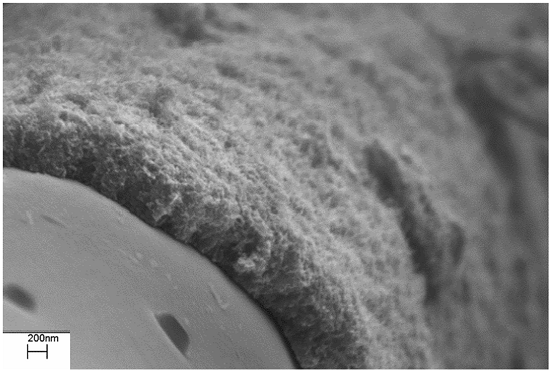
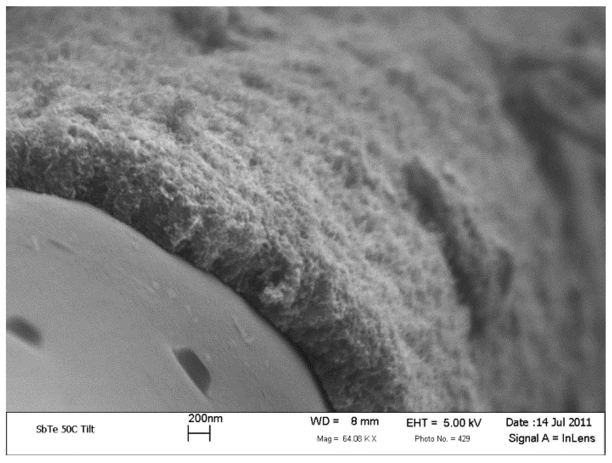
Figure 5 shows SEM micrograph of a cross-sectional view of carbon fiber covered with a dense layer of GSD-grown nanofilament. The thickness of the layer (1 h growth time) is almost 0.5 microns. The length of the grown CNTs can be controlled by the initial thickness of the nickel layer and the growth time. The filament layer seems to be coherent and connected to the surface of the PAN carbon fibers. However, to attain a good adhesion between the polymer/fiber, it is imperative that the polymer matrix infuses into the dense CNT forest.
Figure 5.
Cross-sectional SEM micrograph of a carbon fiber grafted with surface-grown carbon nanofilament utilizing the GSD technique.
Figure 5.
Cross-sectional SEM micrograph of a carbon fiber grafted with surface-grown carbon nanofilament utilizing the GSD technique.
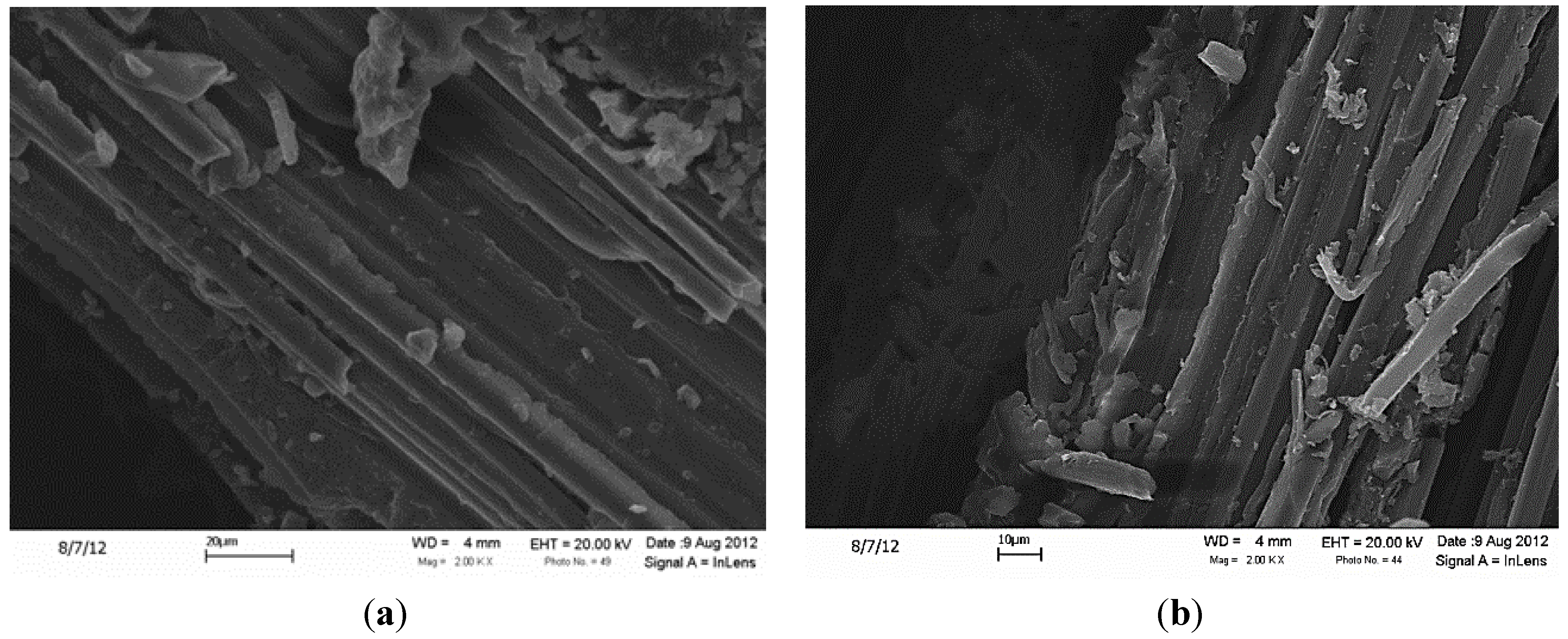
The carbon monofilaments only grew on the exposed fiber bundles on the upper and lower surfaces of the woven carbon fabrics (
i.e., what will be the ply interfaces in a composite lamina). However, they did not influence the polymer matrix penetration to the regions adjacent to the grown nanofilaments (see
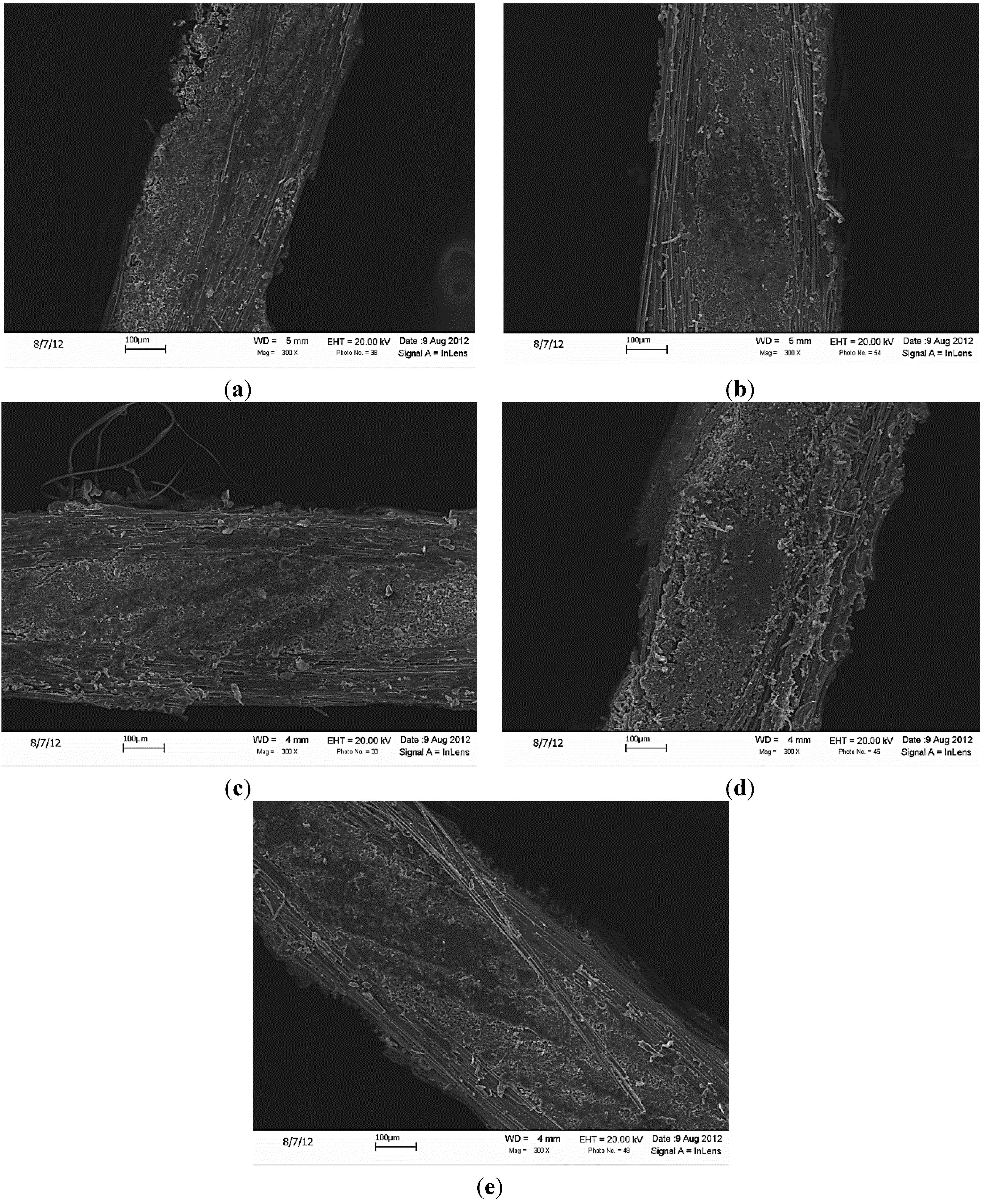
Figure 6). As observed from the SEM micrographs of the cross-sections of different samples (
Figure 7), the overall penetration of the matrix seems to be identical for all the samples. However, while grafting of CNTs was achieved with a minimal weight penalty, it affected the volume fractions of the composite panels. The volume fractions for different composite configurations are summarized in
Table 1.
The tensile test results were, therefore, normalized with respect to the corresponding volume fractions according to the composites rule of mixture. Although the rule of mixture does not provide the most accurate prediction of tensile properties, it is employed here to justify the comparison between the different samples and to provide a better contrast of the effects of the different surface treatments on the tensile properties. The results of the tension tests are summarized in
Table 2.
Figure 6.
Polymer matrix penetration of the region adjacent to the nanofilaments for the composites based on the (a) CCVD and (b) GSD methods.
Figure 6.
Polymer matrix penetration of the region adjacent to the nanofilaments for the composites based on the (a) CCVD and (b) GSD methods.
Figure 7.
The cross-sections of all fabricated composite samples were investigated under scanning electron microscopy (SEM). The cross-sectional images of all samples, as well as the magnified images for the GSD and CCVD samples are shown below. The SEM micrographs show the same level of matrix penetration for all samples. (a) R; (b) R + HT; (c) Sp + HT; (d) GSD; (e) CCVD.
Table 1.
Fiber volume fractions for the specimens based on raw PAN-based carbon fabric (Raw), SiO2 sputter-coated fabric (Sp), heat-treated fabric (HT), SiO2 sputter-coated then heat-treated fabric (Sp + HT) and with CNTs grown on their surfaces via graphitic structures by design (GSD) and catalytic chemical vapor deposition (CCVD).
| Composite Sample | Label | Vf (%) |
|---|
| Raw | R | 56 |
| Heat treated | HT | 57 |
| SiO2 sputter-coated | Sp | 55 |
| SiO2 sputter-coated then heat treated | Sp+HT | 54 |
| CNT grown with GSD | GSD | 49 |
| CNT grown with CCVD | CCVD | 49 |
Table 2.
Tensile mechanical properties for the specimens based on raw PAN-based carbon fabric (Raw), SiO2 sputter-coated fabric (Sp), heat-treated fabric (HT), SiO2 sputter-coated then heat-treated fabric (Sp + HT) and with CNTs grown on their surfaces via GSD and CCVD.
Table 2.
Tensile mechanical properties for the specimens based on raw PAN-based carbon fabric (Raw), SiO2 sputter-coated fabric (Sp), heat-treated fabric (HT), SiO2 sputter-coated then heat-treated fabric (Sp + HT) and with CNTs grown on their surfaces via GSD and CCVD.
| Fiber’s configuration | Young’s modulus (GPa) | Tensile strength (MPa) |
|---|
| Raw | 40.4 ± 1.2 | 606 ± 31 |
| HT | 41.4 ± 0.9 | 556 ± 44 |
| Sp | 40.6 ± 3.6 | 547 ± 42 |
| Sp + HT | 44.1 ± 1.4 | 557 ± 27 |
| GSD | 43.7 ± 2.6 | 585 ± 37 |
| CCVD | 38.9 ± 4.8 | 184 ± 10 |
The normalized mechanical properties (
Table 2) indicate that the stiffness of the composite was retained upon exposure to moderate temperatures (
i.e., 550 °C in N
2 atmosphere). This observation is manifested by the heat-treated fabric (HT) and the HT and SiO
2 sputter-coated fabric (HT + Sp) samples. The surface alteration via coating with SiO
2 and the heat treatment or the presence of GSD-CNTs on the surface resulted in an increase in the stiffness (see
Table 2). However, the sample with CCVD-grown CNTs on the SiO
2 layer exhibited a slight degradation of almost 4% in the stiffness of the corresponding composite. This degradation can be attributed to the higher temperature of the CCVD reaction that accelerates carbon diffusions and partially deteriorates the carbon fiber and, to a lesser extent, to the poor adhesion between the epoxy/fibers and CNT/fiber.
Heat treatment of the carbon fabric also leads to the removal of the sizing and, thus, alteration of the surface of the fibers. Removing the sizing through heat treatment resulted in an 8% reduction in the strength of the composite compared to the reference composite with the sizing intact (
Table 2). The introduction of the SiO
2 layer (Sp sample) lessens the bonding between the epoxy and fibers and, thus, induces a slight reduction in the strength of the composite. The heat treatment of the sputter-coated fabrics (see the Sp + HT sample) does not appear to influence the adhesion of fiber/matrix and the strength of the composites; the strength of the Sp and the Sp + HT composites were virtually identical. Grafting the nanofilaments directly onto the fibers allows for the placement of high volume fractions of un-agglomerated nanofillers. This volume fraction is far larger than what can be effectively achieved when CNTs are pre-mixed with the epoxy matrix (typically within 3% for proper dispersion). It is speculated that the highly viscous matrix (viscosity of 950 cps) might not be efficient in fully impregnating the dense surface-grown nanofilament forests. Conversely, the enhanced fiber/matrix adhesion due to the interactions between the surface grown CNTs and the polymer matrix yielded an improved stress transfer to the fibers compared to all other samples with modified surfaces (
i.e., Sp, Sp + HT and HT). The composite based on the GSD grown nanofilaments counterbalanced some of the undesired effects from the presence of the SiO
2 layer and heat treatment on the strength. While the strength of the GSD samples improved by 5% compared to the Sp + Ht ones, it was still 3.5% lower than the strength of the reference samples. Nevertheless, the harsh thermal environment of CCVD (
i.e., exposure to the temperature of 680 °C) causes drastic degradation of the fibers due to temperature-accelerated diffusion and oxidation of carbon, which deteriorates the carbon fiber core and surface. Moreover, the surface of the fibers is malformed due to the presence of nanofilaments (possibly not fully attached to the fiber) on the surface of the SiO
2-coated carbon fibers. Test coupons based on FRPs with CCVD surface-grown CNTs ruptured in a very brittle manner. A 70% decrease in the strength of the composites based on CCVD-CNTs can be primarily attributed to the severe degradation of the fiber surfaces, due to the elevated synthesis temperatures. Among the tested samples, only the SiO
2-coated (Sp) and SiO
2-coated/heat-treated (Sp + HT) samples exhibited delamination during the tension tests.
The carbon fiber samples were weighed pre- and post-processing in the synthesis reactor. The measurements were repeated for the samples with SiO2 coating only (the Sp + HT sample was considered as the reference for calculating the weight of CNTs) and for the samples with SiO2 coating and nickel catalyst (the ones that CNTs grow on later). Utilizing a digital scale with an accuracy of ±0.0001 g, we conclude that for both samples processed via GSD and CCVD, the weight fractions of the CNTs in the composite is less than 0.05 wt%.
The hand layup process that was used for the fabrication of the panels does not effectively control the volume fractions of composites. However, the normalized tensile test results confirmed the hypothesis that the core of the fibers is unaffected by the elevated reaction temperatures of both GSD and CCVD. Among all the samples, the tensile strength of the panels fabricated from the CCVD-processed fabrics degraded significantly. Thermally-induced surface damage to the fiber surface and the weak interaction between the surface CNTs and polymer matrix are the main reasons for the mechanical weakening of the CCVD composite samples. The conclusion that can be drawn is that the CCVD technique allows for the placement of high-quality crystalline CNTs (compared to the nanofilaments grown via GSD) at the price of significantly degrading the mechanical properties, due to the severe substrate fiber damage.
The reduction of tensile properties of the GSD samples (
Table 2) is at worst 3.5% for the strength. The CCVD yielded even more significant reductions of 4% and 70% for the modulus and the strength, respectively. The degradation of the composites properties due to thermal annealing of the base carbon fibers during CCVD was observed by several other groups. For example, when utilizing CCVD for growing CNTs on the surface of IM7 carbon fibers (much stronger and denser than the AS4 fibers) at 750 °C for 1 h, Qian
et al. [
22] reported a 15%–25% reduction on the tensile strength. Zhang
et al. [
17] performed a CCVD to grow CNTs over T650 and IM7 carbon fibers and observed that the strength of the corresponding composite based on T650 fibers with grafted CNTs compared to composite based on the raw fibers drops by 46% when the growth temperatures was 800 °C. In contrast, under the same growth conditions, the composites based on IM7 carbon fibers with grafted CNTs exhibited a reduction of 70% of the original strength.

 ,
, 


