Abstract
Inefficient utilization of the frequency spectrum due to conventional regulatory limitations and physical performance limiting factors, mainly the Signal to Noise Ratio (SNR), are prominent restrictions in digital wireless communication. Pattern Based Communication System (PBCS) is an adaptive and perceptual communication method based on a Cognitive Radio (CR) approach. It intends an SNR oriented cognition mechanism in the physical layer for improvement of Link Spectral Efficiency (LSE). The key to this system is construction of optimal communication signals, which consist of encoded data in different pattern forms (waveforms) depending on spectral availabilities. The signals distorted in the communication medium are recovered according to the pre-trained pattern glossary by the perceptual receiver. In this study, we have shown that it is possible to improve the bandwidth efficiency when largely uncorrelated signal patterns are chosen in order to form a glossary that represents symbols for different length data groups and the information can be recovered by the Artificial Neural Network (ANN) in the receiver site.
MSC Codes:
68T10
1. Introduction
The fundamental restriction in data transmission through communication channels has two crucial aspects. These are transmitting the data within spectral bandwidth limitations and making this transmission robust to noise with the highest possible data bit rate. As proposed by the Shannon Limit Theorem [1], the channel capacity is directly proportional to the spectral bandwidth and Signal to Noise Ratio (SNR) and in order to maximize the channel capacity both parameters should be optimized.
The ratio of Energy per bit to Noise Power Spectral Density Ratio (Eb/N0) expresses the relation between SNR and Link Spectral Efficiency (LSE). The following equation shows this function. The most important aim of PBCS is to maximize the LSE value at the possible lowest SNR level. This situation directly points the minimization of the area under the graph for Eb/N0 vs. Bit Error Rate (BER) space:
where S is a power of signal, N is a power of noise, W is a spectral bandwidth and C is the channel capacity to transmit the data.
Spectral bandwidth usage is defined in line with certain standards. It needs to be used in the most optimized way to maximize the spectral efficiency. Although conventional RF communication systems concentrate on transmitting the data with the highest possible data rate by using specified modulation methods and certain assigned channels, they neglect to optimize the utilization of the spectral bandwidth. This gap was handled in 1999 by Mitola’s concept of Cognitive Radio (CR) [2] that optimizes bandwidth efficiency by sensing the free spectral bandwidth sections and fills these sections by switching among modulation techniques.
The existing modulation techniques deal with the capacity problem in terms of the speed of data transmission. They manage to work under specified SNR value; still they are far from the Shannon boundary. Therefore, communication systems are in need of a new and efficient spectral bandwidth modulation technique, that allows data transfer with approximately zero BER, even under the influence of higher noise.
The system proposed in this paper involves a new modulation and encoding technique, which consists of the construction of largely uncorrelated signal pattern (waveform) sets called glossaries. Each glossary in the glossary space can be chosen with two components. These are the free SNR capacity of the communication channel and the LSE, which is the proportion of the data bit rate (bps) and the spectral bandwidth (Hz). In this new technique, the channel capacity determines the available data bit rate to perform the transmission. Then, similar to the CR concept, there is an adaptive mechanism in Pattern Based Communication System (PBCS) that switches between the glossaries due to difference between the measured noise level of the assigned channel and the SNR limitation of the glossary that maximizes the LSE.
In the receiver, the disarrangements caused by possible delays and reflections in the communication medium are corrected via a pattern separation process that puts the patterns in correct order (synchronization) and eliminates multipath effect with the time delay estimation algorithms. Then these corrected patterns are fed into the Artificial Neural Network (ANN). Having been trained for all possible sets of glossaries, the ANN recovers the incoming noise added signal pattern into the associated binary code. The information is reconstructed by concatenating these binary codes.
PBCS can provide some advantages for military communications where robustness against noise generated by jammers is an important issue. It can be used to transmit the signal with minimal error, even within improved SNR characteristics, by adaptively switching to an appropriate pattern glossary set. Moreover, since the glossaries are formed by the user, an external party cannot decode the signal pattern without knowledge of the glossary. This also allows the system to be used as part of an encryption system. High link spectral efficiency capability allows an increased data rate in low frequency ranges, which improves the data transfer performance of submarine communication systems.
2. PBCS Model
When the signal from the transmitter reaches the receiver, it is distorted by both natural and man-made noises acting upon it during the transmission process. In the proposed PBCS, the communication task is fulfilled, when, in the receiver, the distorted signal patterns are matched with the original patterns by the ANN, which is trained a priori and offline. The fundamental reason for selecting ANN as the recognition layer of the system is the sensitivity of ANN while recognizing the amplitude, frequency and phase changes in the communication signal. The primary aim of PBCS is to separate the glossary patterns by using this feature of an ANN. From the CR perspective, the PBCS has the objective of optimizing the SNR vs. LSE relationship of the communication system by making dynamic band utilization through pre-defined glossaries, which have distinct characteristics.
A prominent subject under the CR concept is spectrum sensing, on which extensive work has been reported in the literature. This work includes Matched Filtering (MF) [3], Waveform-based sensing, Cyclostationary-based Sensing [4,5], Energy Detector-based Sensing [6] and Radio Identification [7,8]. Among these, MF is the closest method to PBCS. The most significant disadvantage in the practical use of MF is the fact that the information about bandwidth, operating frequency, modulation type and order, pulse shaping, frame format etc. should also be known by the receiver, whereas the proposed system overcomes this disadvantage, since the information is embedded into the ANN recognition process.
There are various methods that utilize ANN to achieve spectrum sensing. Palicot et al. [9] have managed to successfully determine the bandwidth and its shape by using RBNN (Radial-based Neural Network). In another study, Gandetto et al. [10] have used Feed-Forward Back Propagation Neural Networks (FFBPNN) and Support Vector Machine (SVM) with Radial Bases Function (RBF) to make time-frequency analysis. On the other hand, Tsagkaris et al. [11] have introduced and evaluated the learning schemes those are based on artificial neural networks and their study could be used to predict the capabilities (e.g., data rate) of a specific radio configuration. Finally, Fehske et al. [12] have used Spectral Correlation Density (SCD) and Spectral Coherence Function (SCF) to perform Multi-layer Perceptron (MLP) to sense the spectrum. As opposed to these methods, the proposed system develops its own modulation technique by using Amplitude Frequency Phase Shift Keying (AFPSK) and the data communication is achieved when the signal waveforms constructed through this method are recognized by MLP.
The aim of this study is to evaluate the robustness of the proposed system against to the noise model in the communication channel. It is assumed that the effects of other communication channel models are handled by conventional methods in the literature. For instance, the multipath channel model effect on the performance is handled by the time delay estimation algorithm by using ANN [13]. The channel capacity determines the LSE and the measured noise level of the assigned channel points SNR value on the communication band. To select the most appropriate glossary from the glossary space, PBCS uses LSE to obtain from the data transfer rate availability in the channel capacity. Then, it measures the noise level of the assigned channel and it points SNR value on the communication band. Using these two values, it chooses the most appropriate glossary (Gi) from the glossary space (G) for transmission. Since the glossary space is known by both the transmitter and receiver, the received glossary information functions as the switch between ANN’s at the receiver side. The ANN decodes the information and offers it to the user service.
PBCS is designed for multi-purpose utilization as a single-user or multi-user access. Different information sources (Sx, x = 1…n, in Figure 1) can be located in the transmitter side. Tx and Rx point the transmitter and the receiver blocks of PBCS, respectively. As mentioned in a previous study [14], the combined source signals and noise can be separated by the receiver. While the digital information is encoding, each binary word is assigned to the artificially constructed patterns in its glossary. Since this procedure realizes the modulation of the signal, there is no need for additional modulation in transmission. These modulated signals can be simultaneously transmitted through the communication medium. The natural noise is automatically added to these different signal patterns on the communication medium. The antenna at the receiver side percepts the combined and distorted information. Recognition layer can decode this received and synchronized signal. Figure 1 shows the generalized view of the PBCS structure.
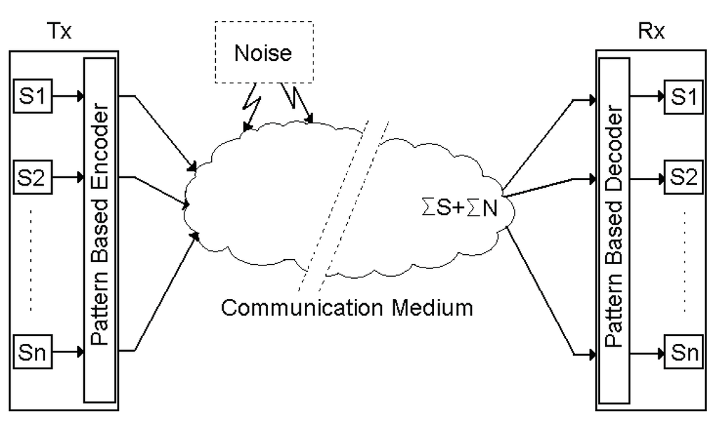
Figure 1.
Generalized pattern based communication system structure.
PBCS requires a dynamic radio frequency (RF) Front-end because of dynamic spectrum utilization. This need was already handled when the studies of Akos et al. [15] in which so-called Direct RF Sampling was applied to the RF Front-end. Then, Psiaki et al. [16] have presented a new algorithm that finds the minimum sampling frequency and thus avoids overlap. The most important advantage of this study was the fact that Direct RF Sampling had the capability of processing multiple-frequency bands using a single front end.
3. PBCS Structure
As in all communication systems, digital information is modulated in the transmitter and demodulated in the receiver based on some method. In PBCS, the modulation is performed by using Sinusoidal Pattern Envelope Construction (SPEC), which will be explained in the following sub-section. On the other hand, the demodulation, which is another important process that determines efficiency and the performance of the system, corresponds to the offline pre-training of the ANN. This will also be explained in the Receiver Structure and ANN Design sub-section.
3.1. Transmitter Structure and Constructing the Glossary
The sequence of M-bit information is fed into a buffer. According to the size of the glossary, buffer takes the n-bit sequence from this information. This n-bit binary sequence is matched with any n-bit glossary (i.e., the binary sequence “010” is mapped to second pattern in selected 3-bit glossary). The encoder output is fed into the pattern sequencer. It concatenates these patterns in sequence. The concatenated pattern sequence is transmitted through RF Front-end. As seen, by not requiring any modulation and/or coding layer, the glossary construction algorithm forms the basis of PBCS. Figure 2 shows the transmitter structure of the PBCS.
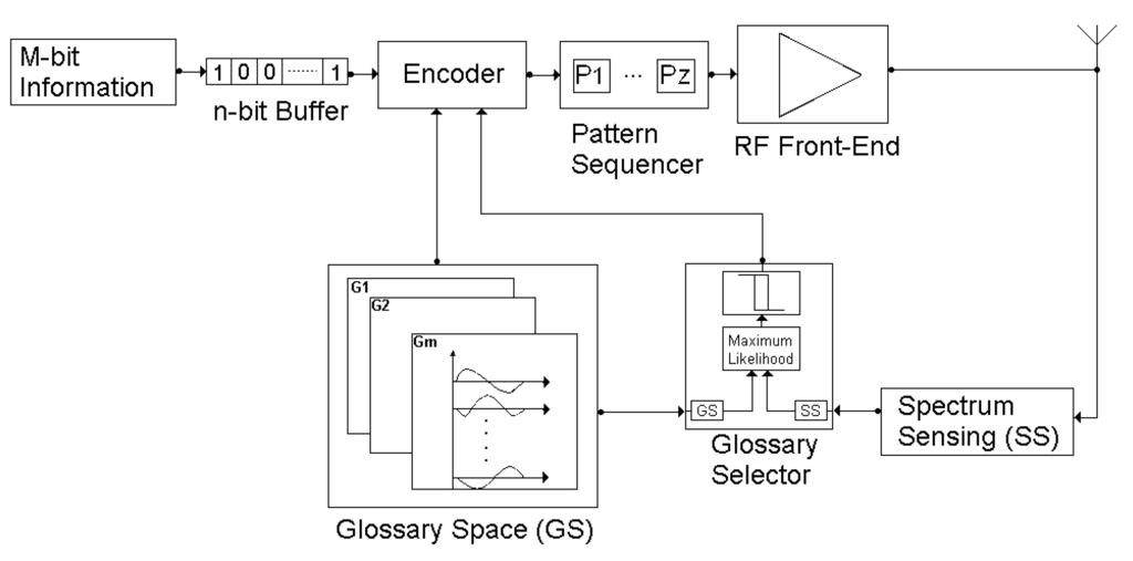
Figure 2.
PBCS transmitter structure.
The “Glossary Selector” block has the most important role in PBCS performance. This block takes the glossary space information and channel spectral situation as an input. According to these inputs, this block calculates the maximum likelihood value. It uses a hysteresis function to determine the set of most proper glossaries in the glossary space. The reason for the usage of the hysteresis function in the glossary selector block is that the system gives the priority to the active glossary to reduce the communication costs. The encoder uses the information of the bit stream size at the buffer and it selects the best-fit glossary from the glossary set given by the glossary selector.
It is assumed that in order to construct the glossary space, the three fundamental parameters of the communication signal need to be shifted. For that reason, the AFPSK modulation method is used in PBCS. On the other hand, as far as the efficient use of spectral bandwidth is concerned, for an optimum solution this shifting operation needs to be sinusoidal instead of linear. For this purpose, the quarter sinus forms have been used as the basis units in the shift keying. The choice of quarter sinuses as the basis bears the advantage of making the shifts in the signal smooth thus prevents the unexpected extra spectral usage. Moreover, as a fundamental necessity of the RF communication, the constructed signal patterns satisfy the following three conditions: (1) Zero DC component: Average of each symbol and the series of symbols must be zero, so that the RF energy can efficiently be transferred. (2) Continuity: First and Second Derivatives of the symbol and the consequent symbols must be continues in order to prevent non-transferrable harmonics beyond the pass-band. (3) Bandwidth limitation: Spectral distribution of the generated signal should ideally be inside the pre-defined frequency interval. These features also provide a perfect fit during the pattern synchronization. SPEC space defined above is shown in Figure 3. One of the alternatives is shown in bold in the following figure.
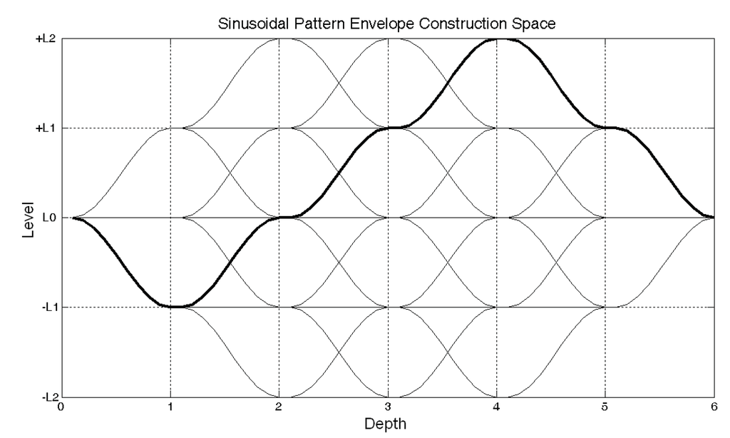
Figure 3.
SPEC space for Level: ±2 and Depth:6.
In Figure 3, the waveform envelope combinations for ±2 levels and 6 depth layers are given as an example. All possible outcomes in the SPEC space are formed by the changes in the amplitude, frequency and phase parameters of the signal. The three possible alterations between each depth layer can be a positive or negative quarter sinus or constant level. Since the changes in the signal parameters form the basis of the pattern system, they should be as uncorrelated as possible in the space in which they are located. Therefore, the glossary patterns are constructed so that depending on the number of bits that the glossary should contain, the most uncorrelated number of sinusoidal changes is chosen (i.e., for a 4-bit glossary, 16 routes). The vertical levels in the SPEC space represent the maximum and the minimum values that any of the signal characteristics can take. For instance, in a case of phase equals to 5 degrees, the spaces defined between the limits +L2 = +5 and −L2 = −5; shifting is made between these two values. Similarly, when the frequency change is chosen to be between 2410 MHz and 2414 MHz, 2414 MHz and 2410 MHz are assigned to +L2 and -L2 respectively. Thus, basic signal glossary space G is formulated in Equation (2):
Each row represents a group of n(x) signal pattern inside the respective SNR and LSE limitations. Although the chosen glossary set Gi can be changed due to channel conditions, the signal pattern sequence is constructed from the same glossary for a certain data frame length. This is required for synchronization between the transmitters and the receivers besides satisfying the continuation of the communication signal. Each communication pattern is the consequence of signal patterns from one of the “m” glossaries. The number of signal pattern n(x) is determined by encoding of the binary data to be transferred. For instance, if Gx is 4-bit glossary, n(x) is set to 16. jth signal pattern from the ith glossary is defined as:
where Ai,j(t), fi,j(t), and Φi,j(t) varies between −1 (minus quarter sinus change) and +1 (plus quarter sinus change) with respect to one of the envelope combinations shown in Figure 3 and they satisfy SNR and LSE conditions assigned for the ith glossary. f0 is the central frequency, A0 is the mean value of amplitude interval, ∆A and ∆f is the allowed limitation on amplitude and frequency change for each level. In the initial condition of t = 0 (at L0), which corresponds to (0, 0, 0) coordinate on the SPEC space, the formula the basic signal pattern is simplified into the following:
3.2. Receiver Structure and ANN Design
In the PBCS receiver the signal distorted by the communication medium arrives at the RF Front-end, where, after a pattern separation (synchronization and elimination of multipath effect) process, it will be fed into the ANN as an input. Since ANN is pre-trained for the patterns, it can recover the distorted signal into known patterns, and outputs the associated bit sequences. These bit sequences are concatenated by the Bit Sequencer layer in order to come up with the original information. This procedure is described below in Figure 4.
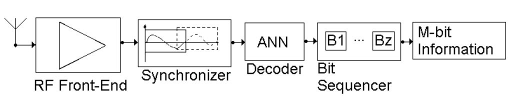
Figure 4.
PBCS receiver structure.
In the receiver, the layer that has the most crucial effect on the performance of the system is the ANN and specifically its design. The ANN design process includes the training and the test procedure. In the training phase, the ANN is trained offline according to the glossary patterns, which are called the training set. Distorted by the communication medium, the training set now becomes the test set, which is used to check the performance of the pre-trained ANN.
The ANN concept was first proposed by Haykin [17] under the name of MLP (Multilayer Perceptron). Hierarchically structured, the ANN achieved successful results in complex classification and pattern recognition problems. Therefore, in this study, ANN is used in order to recognize the signal patterns, which are constructed based on the RF signal construction principles.
The MLP has one input and one output layer, and in addition, it may have one or several hidden layers. Essentially, it is referred to as Black-box in some studies; it aims to determine any function between input and output values. The difference between the output of ANN and the expected output is fed into the system using the back-propagation algorithm. After a number of repetition, which is determined with respect to the user defined finishing criterion, a function can be formulated between the input and the output.
Many methods are developed in the literature for back-propagation algorithms. Since it was the most applicable to the proposed system, the “Steepest Descent” one was chosen in this study. This method based on minimization of the quadratic cost function by tuning the network parameters. The mathematical expression is this algorithm as below:
where w represents the weights of the ANN, k is the number of iterations, ε is error between the output of ANN and the actual value, η is the learning rate. Learning rate can be selected as a constant or an adaptive coefficient. An adaptive learning method is preferred for ANN in the PBCS receiver. The well-known adaptive method for the learning rate update is called as “additive increment and multiplicative decrement”. This approach provides a cost effective solution in terms of simplicity and more robust behavior to find the best value of learning rate. The formulization of this procedure is in the following equation:
Another important aspect in ANN design is to determine the number of hidden layers and of neurons located in these layers. From the low complexity and high applicability perspectives, a single hidden layer is chosen in PBCS design. The number of neurons in this layer is determined by the cross-validation method. On the other hand, the number of neurons at input layer is set as equal to the number of samples for each pattern. The number of neurons at the output layer is selected as equal to the number of patterns in the glossary.
The constructed signal pattern (waveform) P(t), is sampled by the unit time delay and S(t) is obtained with the sample and hold circuit. Each sample corresponds to the neurons of the input layer. The number of neurons in the hidden layer is determined by the cross-validation in an offline process. The outputs y1, y2,…, yq indicates recognition levels between the glossary and the applied signal in the q-tap frame. The encoder block in this figure encodes the ANN output, which is converted into the respective binary signal sequences in the glossary order. The binary sequences at each frame instant are added to recover all the information at the receiver where these frames were encoded by ordering the patterns at the origin.
The error in ANN is calculated in terms of mean squared error (MSE). The aim is to decrease this error at each training and to finally bring it below the user defined threshold. The resulting error value is given in the equation below:
where d is the actual response and y is calculated response. The difference between them signed as error (e). q represents the number of neuron at output layer. MSE can be calculated as:
where e, D, τ and ε denote error of neural network at output, dimension of array, total number of patterns in the training set and mean squared error sequentially.
The synaptic weights are adjusted to minimize the quadratic cost function. However this process is different between the layers. For example, the adjustment of synaptic weights between hidden layers and output layer is given by the Equation (10) and Equation (11):
where ψ is activation function, which will be explained below in detail. H represents the number of neuron at hidden layer. Furthermore, the adjustment of synaptic weight coefficients between the input layer and the hidden layer is given by Equation (12):
where I represents the number of neuron at input layer and η indicates learning-rate. Designer can design it as constant or adaptive. In case the network does not converge, Rumelhart et al. [18] has generalized the formula. It uses to determine weight coefficients including α momentum parameter. This formula is given in Equation (13):
The activation function is effective on the sensitivity of the output layer. There are many activation functions in the literature. Three main functions are called sigmoid, linear and tangent hyperbolic and are shown in Figure 5. Due to the appropriation of upper and lower limit and its transition function, the sigmoid function has been selected as the activation function in our case. The problem in this system is to determine which pattern has been entered by the input layer. Therefore, the output corresponding to the input pattern should be one, and the rest should be zero. The most proper activation function for this purpose is the sigmoid as given in Equation (14):
However, this function carries the problem of determining a constant (“λ”) at the formula, which affects the performance of the ANN directly. This value is determined by test experiments.
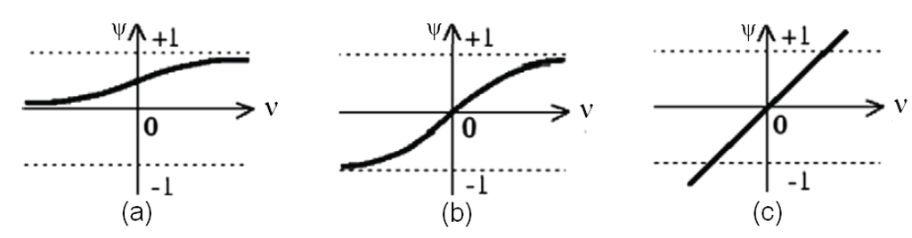
Figure 5.
Activation Functions: (a) Sigmoid, (b) Tangent Hyperbolic, (c) Linear.
The parameters used in this system are the constant user defined momentum coefficient and the adaptive learning rate coefficient. The hidden layer neuron quantity of ANN is determined by the cross-validation algorithm. The Sigmoid activation function was selected in the output layer. The ANN design obeying the above constraints is represented in Figure 6.
Both the transmitter and receiver sides of PBCS are formed in line with unique algorithms in order to enable a more dynamic utilization for the communication medium. The following section will cover and analyze the simulation results regarding the design process of PBCS.
4. Simulation and Test Results
The objective of this study was to design a system which can manage SNR vs. LSE relationship depending on the user expectations and spectrum availabilities. In line with this objective, for each bit level, distinct glossaries were constructed and the number of neurons in the associated ANN is determined through the cross-validation process. The results of this process are given below.
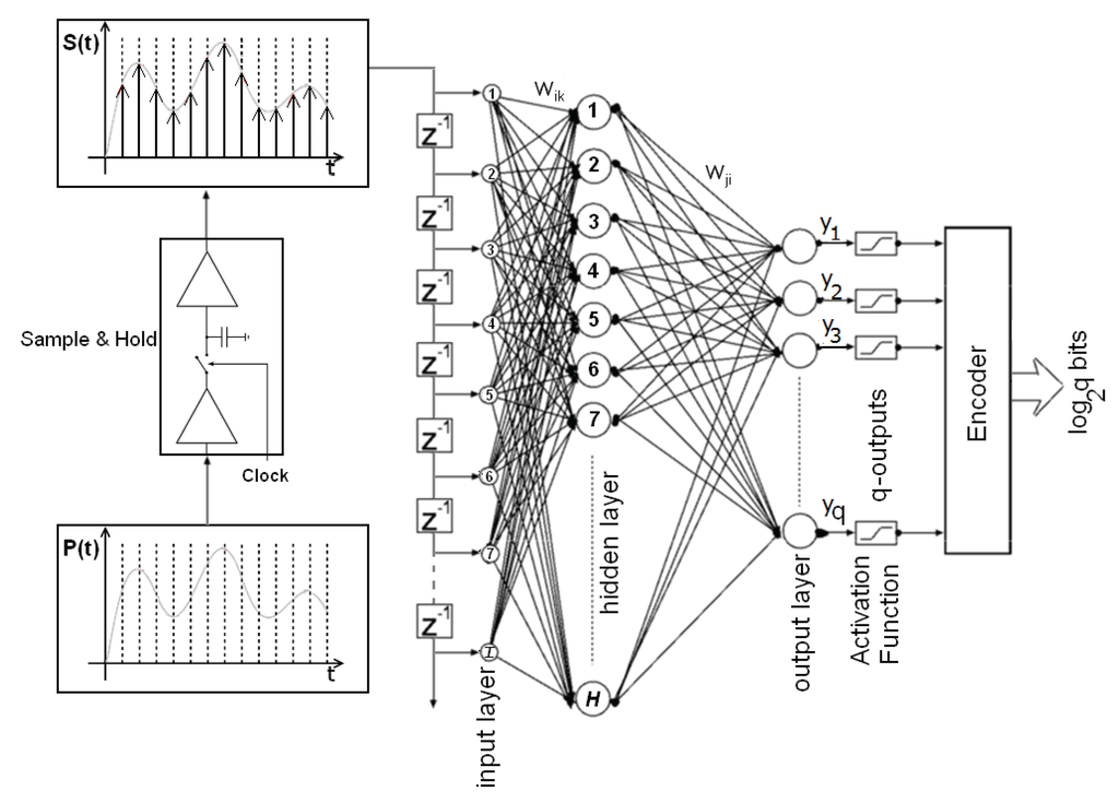
Figure 6.
The general view of MLP neural network architecture. P(t) is the pattern in the active glossary, and S(t) is the sampled form of the pattern.
The most important innovation in PBCS is to design a system, which can manage SNR depending on the user request in terms of LSE. According to the user request and channel conditions, it switches the communication signals and find out the best point. Six different glossaries are constructed with different boundary conditions for the signal parameters (A, F and P). These glossaries are constructed by the usage of SPEC algorithm for depth 6 and level ±2. MLP is designed with single hidden layer. The number of neurons in the hidden layer is determined with the cross-validation method (Figure 7). The momentum coefficient is set to 0.5. The coefficient for the sigmoid is selected as λ = 0.6. The learning rate is adjusted in adaptive manner. The glossary space G is constructed with these rules and parameters. This matrix has six rows and each row has different number of column regarding the bit level of glossary. Some glossaries constructed with the SPEC algorithm are listed in Table 1. These values indicate the interval boundaries in SPEC space. Minimum and maximum values for each feature points –L2 and +L2 levels, respectively.
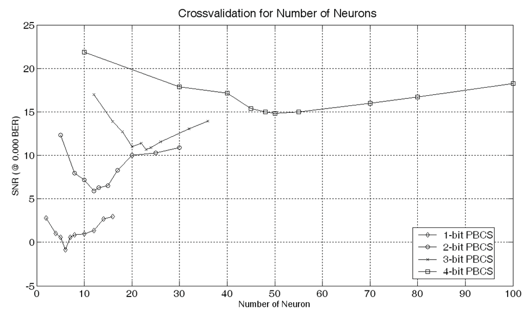
Figure 7.
Cross-validation for determining the number of neurons.

Table 1.
Glossary interval boundaries for SPEC space @ 2.412 GHz central frequency.
| Glossary | Amin (V) | Amax (V) | Fmin (MHz) | Fmax (MHz) | Фmin (°) | Фmax (°) |
|---|---|---|---|---|---|---|
| G1 (1-bit) | 0.09 | 0.10 | 2410 | 2414 | −45 | +45 |
| G2 (1-bit) | 0.09 | 0.10 | 2401 | 2423 | −90 | +90 |
| G3 (1-bit) | 0.09 | 0.10 | 2410 | 2414 | −15 | +15 |
| G4 (2-bit) | 0.09 | 0.10 | 2401 | 2423 | −90 | +90 |
| G5 (4-bit) | 0.09 | 0.10 | 2410 | 2414 | −35 | +35 |
| G6 (4-bit) | 0.09 | 0.10 | 2408 | 2416 | −35 | +35 |
The Shannon boundary is drawn by using the Shannon limit theorem that is based on a function of signal bandwidth and the SNR rate [1] of the system. Just the parameters of this theorem are adapted to the space parameters of SNR vs. LSE. Hence Equation (15) is derived and Shannon boundary line in Figure 8 is drawn with respect to Equation (15):
Figure 8 shows the flexible structure of PBCS in SNR vs. LSE space. Many distinct glossaries are constructed by using the SPEC algorithm and the AFPSK method. Constructed communication signals are then band pass filtered with respect to IEEE 802.11.a/g channel mask model [19]. According to the user demand and channel conditions, PBCS switches to the best point for optimizing the communication system performance. The marks in Figure 8 show the best working point regarding the glossary at 10−5 BER.
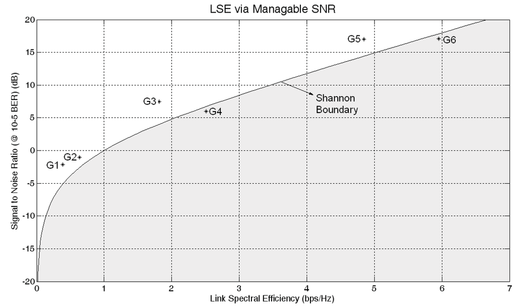
Figure 8.
LSE via manageable SNR and comparison with Shannon boundary.
The most significant feature of the proposed method is its competence to operate at a region around Shannon boundary. This provides the manageable SNR capability by adaptive switching to optimal signal pattern (communication waveform) set between high noise redundancy and high data bandwidth requirements under observed spectrum conditions. Since the pre-trained signal patterns are used in this system; the Shannon boundary is seen as it is virtually broken at some points (G4 and G6) in SNR vs. LSE space. This depends on the difference between the bandwidth of recovered digital data based on priori information in glossary and the raw physical data bandwidth inside the communication medium. In other words, use of predefined patterns in glossaries also provides a sort of soft compression of the information and virtually working beyond the Shannon boundary depends on the nature of data and the selected glossary features. In fact, since a sort of error recovery is also processed during the decoding of the received signal by a trained ANN, it cannot be seen as violation of the physical limitation set by Shannon Theorem.
Another observation is that the PBCS is robust to high levels of Additive White Gaussian Noise (AWGN). Figure 9 represents the distortion effect of the AWGN on the signal patterns for the selected SNR values. The pre-trained ANN can recognize the pattern under this noise pressure. This distortion on one of the glossary pattern G1 is shown in Figure 8. The data is recovered under −2.12 dB SNR value with 10−5 BER.
The comparison between the Eb/N0 curves of the PBCS for specific glossaries and of the MF performance is given in the Figure 10.
According to the performance evaluation, the proposed method gives better results than the MF for specific glossaries. This figure shows that G4 has 28.2% and G2 has 92.2% better performance than MF. These values are derived from the area calculation under the graph between ultimate Shannon limit (−1.59 dB) and 10 dB in Figure 10. SNR level affects the Eb/N0 value exponentially, although the LSE is linear dependent. Therefore, the slope of the curve takes different positions regarding to the position of the glossary in SNR vs. LSE space. It must be considered that besides the use of fixed signal pattern sets (Glossary) for each graph in simulation results, performance optimization of the PBCS mainly depends on adaptive switching between set of patterns due to SNR capability and the sensed SNR under dynamic requirement and availability variations. MF has better performance than G4 for high BER values when the comparison is made for fixed glossary set.
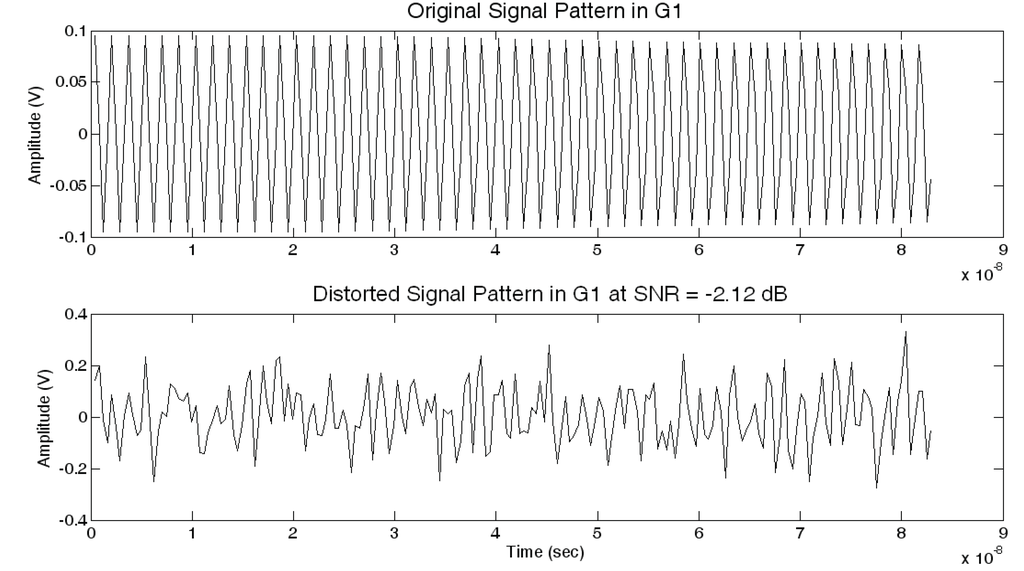
Figure 9.
The distortion on signal pattern with AWGN in Glossary 1 (G1).
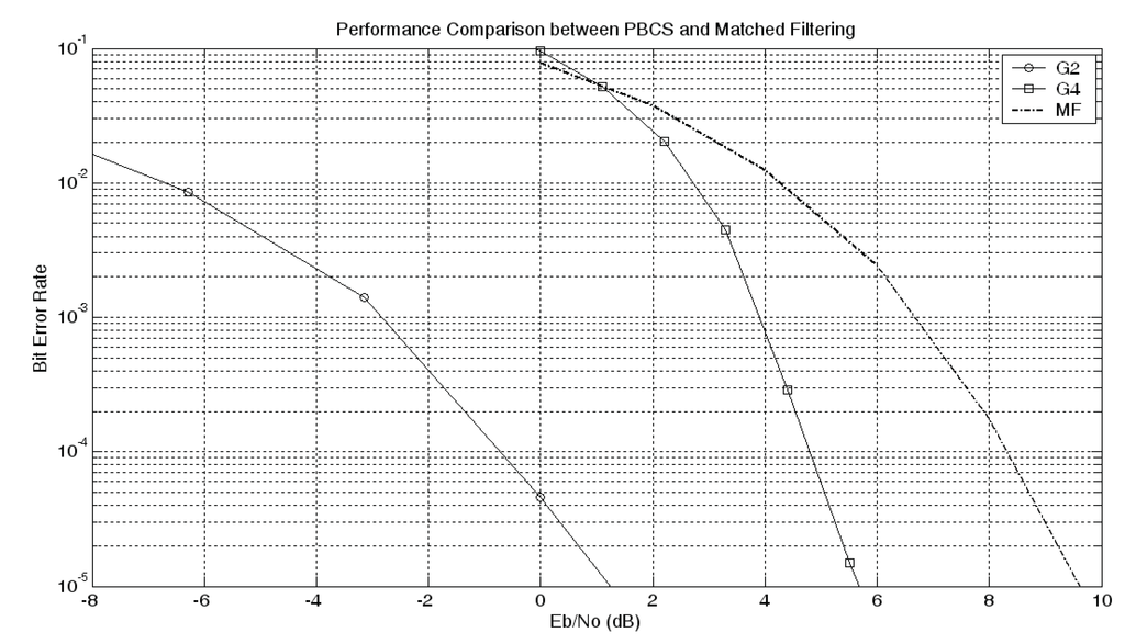
Figure 10.
Performance comparison between PBCS and matched filtering.
A block diagram of a semi-hardware lab test platform is shown in Figure 11. This test platform is independent of RF front-end features and designed to confirm assumptions at baseband only. ANN and the calculations are performed on a PC connected via I/O cards.
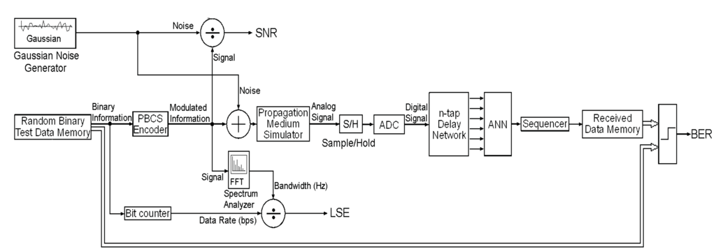
Figure 11.
Block diagram of PBCS test platform.
Some glossaries constructed with SPEC algorithm for 8 KHz central frequency are listed in Table 2. These glossaries are used to test baseband performance of PBCS.
Table 2.
Glossary interval boundaries for SPEC space @ 8 kHz central frequency.
| Glossary | Amin (V) | Amax (V) | Fmin (Hz) | Fmax (Hz) | Фmin (°) | Фmax (°) |
|---|---|---|---|---|---|---|
| G7 (1-bit) | 0.75 | 1.00 | 7995 | 8005 | −5 | +5 |
| G8 (1-bit) | 0.50 | 1.00 | 7998 | 8002 | −3 | +3 |
| G9 (1-bit) | 0.01 | 1.00 | 7990 | 8010 | −10 | +10 |
Randomly generated binary information is encoded here by the PBCS encoder. The base frequency is selected as 8 kHz for the principle validation. The spectral bandwidth utilization is measured through a spectrum analyzer. Each pattern in baseband is sampled by 40 kHz Analog to Digital Converter (ADC). The digital information is fed into ANN by the use of Delay Network. ANN decodes the digital signal to binary words and the sequencer concatenates the ANN output. The comparator measures the BER with respect to buffered original and the information recovered by the PBCS receiver. LSE values for three different glossaries at three different SNR rates are listed in Table 3.
Table 3.
PBCS performance analysis @ 8 kHz test platform.
| Input | Output | |||
|---|---|---|---|---|
| Glossary | Bandwidth (Hz) | BER | SNR (dB) | LSE (bps/Hz) |
| G7 | 5.75 | 10−5 | 20.25 | 10.869 |
| G8 | 7.21 | 10−5 | 15.75 | 8.668 |
| G9 | 381.56 | 10−5 | −3.10 | 0.163 |
In real-time applications, multi-path effect is an important factor that is effective in both RF communication and underwater ultrasonic communication. Although we have developed solutions by making some improvements to the ANN structure against multi-path effect problems, they have not been taken into consideration here in order not to increase complexity at this level. Solutions and performance for medium property related problems within specified frequency range will be published as joint work of this study.
As shown by the simulation results, PBCS provides the advantage of selecting the most suitable point among different possible combinations in the SNR vs. LSE space. Practically, there are two significant problems of PBCS a) high sampling rate and processing power requirement, if direct RF sampling is preferred after RF signal receiver b) on-line training of ANN with the received signal, if it is down converted to baseband. The minimum sampling rate should be twice the central frequency according to the Nyquist Theorem. Moreover, the recognition layer, namely ANN, can be realized either by a floating point Digital Signal processor (DSP) or a Field Programmable Gate Array (FPGA) with sufficient amount of multiplier and adder elements inside. A critical consideration is the recognition time performance of the neural receivers in hardware design. We preferred using FPGAs instead of DSPs especially for the recognition mechanism since the progress can totally be mathematically modeled and requires higher speed processing as the base frequency increases. Although the decoding process takes around 0.00014 s/bits during the given simulations on a standard PC platform (Intel T2400 @ 1.83 GHz for MATLAB on a Windows XP system), this changes dramatically when we directly program on an embedded system. FPGA based hardware implementation also provides real time performance assurance. For example the FPGA EP4SE230 from Altera STRATIX IV E family has 18-bit 1,288 multipliers in one package and this allows the construction of neural networks with 120 by 5 by 2 neurons in each layer respectively. These numbers indicate the quantity of nodes in the input, hidden and output layers of any used neural network in simulation results for 1-bit glossary.
5. Conclusions
Inspired by the recognition capability of the human, Pattern Based Communication System (PBCS) follows the perceptual selectivity of a human being. When a human recognizes sounds, the brain keeps perceiving sounds in the native language while shutting down to the others. The trained brain can selectively focus on to chosen conversation among all other sounds even if its portion is much less than all other heard sounds at same time. In PBCS, the communication system selectively recognizes and recovers the communication signal in known patterns and just like the human brain it ignores the unknown patterns. The objective of PBCS is to optimize the data transmission performance under varying spectral and SNR limitations.
In this study we proposed a signal construction method called SPEC for PBCS so that the user can construct band limited glossaries for different target data transmission rates and SNR values. The signal patterns (waveforms) are constructed according to proposed SPEC method and matched with the binary information in the transmitter in computer simulation and the laboratory tests. The distorted and received communication signal pattern is recovered by an Artificial Neural Network (ANN) implemented on a PC in both cases. The output is then concatenated by the bit sequencer to obtain the original information. During the laboratory tests, generated and distorted signals patterns are sampled in the baseband and processed on a scaled PC platform after digitalization. The low frequency laboratory measurements (Table 3) validate the simulation results when we neglect communication medium property related effects. As a result, SPEC method provides the necessary band limited and perceivable signals for pattern glossaries of PBCS and the proposed system offers advantages for variable communication performance requirements between noise redundancy and high link spectral efficiency.
References
- Shannon, C.E. A mathematical theory of communication. Bell Syst. Tech. J. 1948, 27, 623–656. [Google Scholar] [CrossRef]
- Mitola, J. Cognitive radio for flexible mobile multimedia communications. In Proceedings of the IEEE Mobile Multimedia Communications, MoMuC’99, San Diego, CA, USA, 15–17 November 1999; pp. 3–10.
- Turin, G.L. An introduction to matched filters. IRE Trans. Inform. Theor. 1960, 6, 311–329. [Google Scholar] [CrossRef]
- Gardner, W.A. Signal interception: A unifying theoretical framework for feature detection. IEEE Trans. Commun. 1988, 36, 897–906. [Google Scholar]
- Gardner, W.A.; Spooner, C.M. Signal interception: Performance advantages of cyclic-feature detectors. IEEE Trans. Commun. 1992, 40, 149–159. [Google Scholar] [CrossRef]
- Urkowitz, H. Energy detection of unknown deterministic signals. Proc. IEEE 1967, 55, 523–531. [Google Scholar] [CrossRef]
- Arslan, H. Cognitive Radio, Software Defined Radio, and Adaptive Wireless Systems; Springer: Dordrecht, The Netherlands, 2007. [Google Scholar]
- Yücek, T.; Arslan, H. A survey of spectrum sensing algorithms for cognitive radio applications. IEEE Commun. Surveys Tuts. 2009, 11, 116–130. [Google Scholar] [CrossRef]
- Palicot, J.; Roland, C. A new concept for wireless reconfigurable receivers. IEEE Commun. Mag. 2003, 41, 124–132. [Google Scholar] [CrossRef]
- Gandetto, M.; Guainazzo, M.; Regazzoni, C.S. Use of time-frequency analysis and neural networks for mode identification in a wireless software-defined radio approach. EURASIP J. Appl. Signal Process. 2004, 2004, 1778–1790. [Google Scholar] [CrossRef]
- Tsagkaris, K.; Katidiotis, A.; Demestichas, P. Neural network-based learning schemes for cognitive radio systems. Comput. Commun. 2008, 31, 3394–3404. [Google Scholar] [CrossRef]
- Fehske, A.; Gaeddert, J.; Reed, J. A new approach to signal classification using spectral correlation and neural networks. In Proceedings of the IEEE International Symposium on New Frontiers in Dynamic Spectrum Access Networks, Baltimore, MD, USA, 8–11 November 2005; pp. 144–150.
- He, Z.Y.; Li, H.L. High-resolution multipath time delay estimation using a neural network. In IEEE Proceedings of the Acoustics, Speech, and Signal Processing, Toronto, Canada, 14–17 April 1991; Volume 2, pp. 1469–1472.
- Üstündag, B.; Orcay, O. Pattern Based Encoding for Cognitive Communication. In Proceedings of the IEEE 3rd International Conference on Cognitive Radio Oriented Wireless Networks and Communications, Singapore, 15–17 May 2008; pp. 1–6.
- Akos, D.M.; Stockmaster, M.; Tsui, J.B.Y.; Caschera, J. Direct bandpass sampling of multiple distinct RF signals. IEEE Trans. Commun. 1999, 47, 983–988. [Google Scholar] [CrossRef]
- Psiaki, M.L.; Steven, P.; Jung, P.H.; Kintner, P.M. Design and practical implementation of multi-frequency RF front ends using direct RF sampling. IEEE T. Microw. Theory 2005, 53, 3082–3089. [Google Scholar] [CrossRef]
- Haykin, S. Neural Networks, A Comprehensive Foundation; Prentice Hall: Upper Saddle River, NJ, USA, 1999. [Google Scholar]
- Rumelhart, D.E.; Hinton, G.E.; Williams, R.J. Learning representations by back-propagating errors. Nature 1986, 323, 533–536. [Google Scholar] [CrossRef]
- IEEE Computer Society. IEEE Standards Interpretation for IEEE Std 802.11TM-2007: IEEE Standard for Information technology—Telecommunications and information exchange between systems—Local and metropolitan area networks—Specific requirements—Part 11: Wireless LAN Medium Access Control (MAC) and Physical Layer (PHY) Specifications; 2008; IEEE Std. 802.11.TM. [Google Scholar]
© 2011 by the authors; licensee MDPI, Basel, Switzerland. This article is an open access article distributed under the terms and conditions of the Creative Commons Attribution license (http://creativecommons.org/licenses/by/3.0/).