A Hybrid Cooperative Coding Scheme for the Relay-Eavesdropper Channel

Abstract
: This paper considers the four-node relay-eavesdropper channel, where a relay node helps the source to send secret messages to the destination in the presence of a passive eavesdropper. For the discrete memoryless case, we propose a hybrid cooperative coding scheme, which is based on the combination of the partial decode-forward scheme, the noise-forward scheme and the random binning scheme. The key feature of the proposed hybrid cooperative scheme is that the relay integrates the explicit cooperation strategy and the implicit cooperation strategy by forwarding source messages and additional interference at the same time. The derived achievable secrecy rate shows that some existing works can be viewed as special cases of the proposed scheme. Then, the achievable secrecy rate is extended to the Gaussian channel based on Gaussian codebooks, and the optimal power policy is also identified in the high power region. Both the analysis and numerical results are provided to demonstrate that the proposed hybrid cooperative coding scheme outperforms the comparable ones, especially in the high power region.1. Introduction
The concept of information theoretic secrecy was first introduced by Shannon in [1], where a key is used to protect confidential messages over noiseless transmissions. When considering the noisy transmission, Wyner introduced the wiretap channel in [2], where the received signal at the eavesdropper was assumed to be a degraded version of the signal at the legitimate receiver. Csiszár and Körner extended this degraded wiretap channel to a more general broadcast channel with confidential messages and found the secrecy capacity in [3]. Wyner’s channel has also been extended to the wiretap channel with side information, where the side information was assumed to be non-casually known to the transmitter [4,5]. Recently, secrecy problems have been considered in various multi-user setups. For example, multiple access channels (MACs) were studied in [6–9], where an external eavesdropper was introduced in [6,7], while each legitimate user in [8,9] acted as an eavesdropper for the messages intended to the other users. Broadcast channels (BCs) were considered in [10,11], where each user is also an eavesdropper for the messages intended to the others. Relay channels were studied in [12–17], where an external eavesdropper was introduced in [12–15], while the relay node in [16,17] was an untrusted helper, i.e., this untrusted helper also acted as an eavesdropper to the main receiver.
Since user cooperation can potentially enhance the security, many existing works have designed cooperative secure transmission schemes for multi-user networks. These existing cooperation schemes can be divided into two different types: the explicit cooperation strategy and the implicit cooperation strategy. The explicit cooperation strategy means that the helper nodes send messages that are correlated to the intended messages, such as the decode-forward (DF) scheme [12] or the partial DF [13] for relay-eavesdropper channels. The implicit cooperation strategy requires helper nodes to send interference messages that are independent of the intended messages, such as cooperative jamming (CJ) [6], noise-forward (NF) [12] and the interference-assisted scheme [14].
Different from these works in [6,12–14] that consider these two types of cooperation strategies separately, this paper aims to design a hybrid cooperative coding scheme that integrates the explicit cooperation strategy and the implicit cooperation strategy together. Most recently, hybrid cooperative coding schemes have been considered in [7,15] for the MAC channel with conference and secrecy constraints. Compared to the works in [7,15], which are based on an assumption that there exist secret communication links between a source and its helper partner, the proposed hybrid cooperative coding scheme is applicable to a more practical relay-eavesdropper channel in which the transmissions from the source to the relay can be overheard by the eavesdropper.
The contributions of the this paper can be summarized as follows. Firstly, we propose a hybrid cooperative coding scheme for the four-node relay-eavesdropper channel, where a relay node helps the source to send secret messages to the destination in the presence of a passive eavesdropper. The basic idea is to combine the partial DF scheme [18] for relay channels, the NF [12] scheme for relay-eavesdropper channels and random binning [2] for wiretap channels. Note that the NF and random binning schemes can provide useful randomness to protect the secret messages. The key feature of the proposed hybrid cooperative scheme is that the relay integrates the explicit cooperation strategy and the implicit cooperation strategy by forwarding source messages and additional interference at the same time. The derived achievable secrecy rate shows that the proposed scheme generalizes some existing works, such as the DF [12], partial DF [13] and NF [12] schemes for relay-eavesdropper channels. Secondly, the achievable rate result is extended to the memoryless Gaussian channel based on Gaussian codebooks. Then, the optimal power policy is developed for the proposed scheme in the high power region, and the result shows that the secrecy rate achieved by the proposed scheme can be sufficiently large in the high power region, even if the source-relay link is weak. This is benefited from the fact that the interference generated at the relay can protect the transmissions from the source to the relay by confusing the eavesdropper. Finally, we illustrate the proposed scheme through some examples of the Gaussian network topologies. The numerical results show that our scheme outperforms the comparable ones, especially when the transmit power is large.
In the following, the details about the differences between the proposed scheme and the existing ones are provided in order to further highlight the contribution of this paper.
The channel model and the coding scheme developed in [19] are fundamentally different from those in this paper. First, the work in [19] considers the relay-eavesdropper channel model with parallel subchannels, whereas this paper considers the relay-eavesdropper channel model with only a single communication channel. Second, the coding scheme in [19] uses a subset of channels to perform the DF scheme and the remaining ones to perform the NF scheme, and the interaction between these two relaying schemes exists only across different subchannels. In contrary, by using the superposition coding scheme, the partial DF and NF schemes in the proposed coding scheme are strongly connected to each other in the same channel.
The work in [20] combined partial DF, NF and compress-and-forward (CF) schemes for the discrete memoryless relay-eavesdropper channel. In Section 3.4, we will show that the use of the CF scheme does not offer any performance gains in terms of the secrecy rate. Compared to the scheme in [20] that is based on the successive decoding strategy for separately decoding different messages, the proposed scheme utilizes the backward decoding strategy to jointly decode the common part (known by both the source and relay) of the source messages. Moreover, the proposed scheme decodes the interference messages from the relay after decoding the common part of the source messages, whereas the scheme in [20] decodes these two types of messages in a reversed order. This results in different secrecy rates achieved by these two coding schemes, and their performances will be compared in detail in Section 3.4.
The rest of this paper is organized as follows. In Section 2, the notations, the channel model and the main result are given for the discrete memoryless relay-eavesdropper. Section 3 extends the main result to the Gaussian case, for which an achievable secrecy rate, a power policy in the high power region and some numerical results are provided. The achievable secrecy rate associated with the proposed hybrid coding scheme for the discrete memoryless relay-eavesdropper channel is established in Section 4. Finally, conclusions are provided in Section 5.
2. System Model and Achievable Secrecy Rate
2.1. Notations
Throughout this paper, a random variable, its realization and its finite alphabet are denoted with an upper case letter (e.g., X), the corresponding lower case letter (e.g., x) and the corresponding calligraphic letter (e.g.,
 ), respectively. The probability distribution of the random variable, X, is denoted as p(x) = pX(x) for simplicity, where x ∈
. Furthermore, we use Xn to denote a random n-vector (X1, …, Xn) and use xn = (x1, …, xn) to denote a specific n-vector value in
), respectively. The probability distribution of the random variable, X, is denoted as p(x) = pX(x) for simplicity, where x ∈
. Furthermore, we use Xn to denote a random n-vector (X1, …, Xn) and use xn = (x1, …, xn) to denote a specific n-vector value in
 , which is the n-th Cartesian power of
.
, which is the n-th Cartesian power of
.
Moreover, let Xi and X(]i [) denote the set {X(j), 1 ≤ j < i} and the set {X(j), 1 ≤ j < i or i < j ≤ n}, respectively. In addition, [1 : B] = {1, 2, …, B}, [x]+ = max{x, 0}, , and ∊k is arbitrarily small positive number for ∀κ. Finally, denotes the set of jointly typical n-sequences with respect to p(x1, x2) (more details can be seen in [21]).
2.2. Discrete Memoryless Relay-Eavesdropper Channel
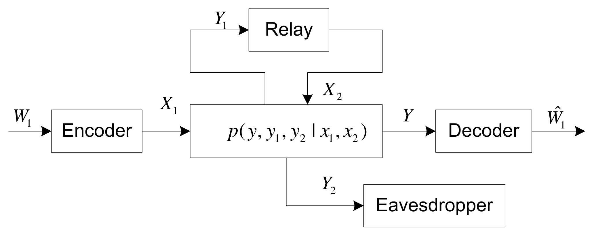
As shown in Figure 1, this paper considers a four-node discrete memoryless channel, where the source (X1) wishes to send a message W1 ∈
 = {1, …, M} to the destination (Y), while keeping it secret from an external eavesdropper (Y2), with the help of a full duplex relay node, (X2, Y1). This channel is first introduced in [12], termed as the relay-eavesdropper channel, which consists of a transition probability distribution (
 ×
×
 , p(y, y1, y2|x1, x2),
  ×
×
 ×
×
 ). Here, the finite sets,
,
, denote the input alphabets at the source and the relay, respectively, while the finite sets,
,
,
, denote the output alphabets at the destination, the relay and the eavesdropper, respectively. The (M, n,) code of this system consists of a stochastic encoder, f1, at the source that maps the message, W1, into a codeword,
, a stochastic encoder, f2, at the relay that maps its received signals (Y1,1, …, Y1,i−1) before time i into a channel input, X2,i, and a decoding function φ :
). Here, the finite sets,
,
, denote the input alphabets at the source and the relay, respectively, while the finite sets,
,
,
, denote the output alphabets at the destination, the relay and the eavesdropper, respectively. The (M, n,) code of this system consists of a stochastic encoder, f1, at the source that maps the message, W1, into a codeword,
, a stochastic encoder, f2, at the relay that maps its received signals (Y1,1, …, Y1,i−1) before time i into a channel input, X2,i, and a decoding function φ :
 → W1. The average error probability is:
The secrecy level is measured by the equivocation rate . A prefect secrecy rate, Rs, is said to be achievable if for any ε > 0, there exists a sequence of codes (M, n,), such that:
2.3. Achievable Secrecy Rate
Before the presentation of our main result, we first define some parameters as follows.
Definition 1
Let ℘ denote the set of all the joint distributions of the random variables (U, V1, X1, X2, Y1, Y2) that factor as:
In this definition, one can observe that (V1, X1) − U − X2 is a Markov chain, where U represents the common message known by the source and the relay. Conditioned on U, (V1, X1) and X2 can be generated at the source and the relay, respectively.
Definition 2
For a given p ∈ ℘, define two rates, R11(p) and R12(p), as:
Note that R11(p) is the rate of the private secret message at the source that is not known by the relay, while R12(p) is the rate of the common secret message that is known by the source and the relay.
Based on the above definitions, the following theorem gives an achievable secrecy rate for the discrete memoryless relay-eavesdropper channel.
Theorem 1
For the considered relay-eavesdropper channel, the following secrecy rate is achievable.
Proof
The proposed achievable scheme is based on the careful combination of the partial DF [18] scheme for relay channels, the NF scheme [12] for relay-eavesdropper channels and random binning for wiretap channels [2]. Specifically, the proposed coding scheme integrates some essential techniques, such as rate splitting, superposition Markov block encoding [18] (Theorem 7), random binning [2], backward decoding and interference injecting [12], etc. In the following, we will outline the proposed hybrid cooperative coding scheme, and the details of the complete proof will be provided in Section 4. (Note that in the next paragraph, a message is said to be a common message if it has been known by both the source and the relay in a certain block, such as w0b in Block b. Otherwise, it is said to be a private message, such as w11b and w2b, which are only known by the source and the relay, respectively.)
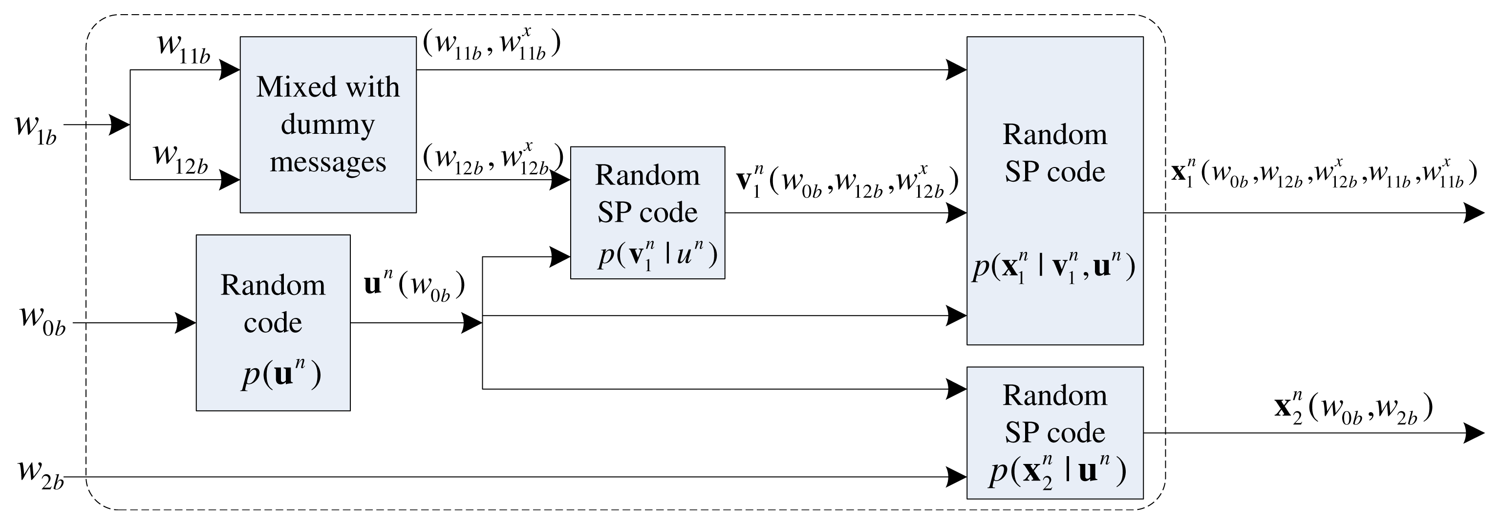
Briefly speaking, for a given joint distribution, p ∈ ℘, the whole transmission duration is formed by B Markov blocks, in which B −1 secret messages will be sent. At Block b, the new secret message, w1b, is first split into two parts: one part needs to be transmitted directly from the source to the destination (w11b); and the other part needs to be decoded by the relay (w12b). Here w11b and w12b are mixed with dummy messages and , respectively. In the encoding process, the random variable, U, in Theorem 1 represents the common message . Note that w0b was decoded by the relay at the end of the previous block, i.e., Block b−1, and becomes the common message in this block. The random variable, V1, represents the superposition code in which the new message (w12b,) is superimposed on the common message, w0b, where (w12b,) needs to be decoded by the relay at the end of Block b and will become the common message, w0b+1, in Block b + 1. In this sense, V1 also carries the common part of the source message, but for the next block. The channel input, X1, represents the superposition code in which the private message (w11b,) is superimposed on w0b and (w12b,). At the same block, noise injection is realized at the relay via sending the so-called “interference message”, w2b, i.e., the relay randomly generates a private interference message, w2b, in order to confuse the eavesdropper. The channel input, X2, represents the superposition code in which the interference message, w2b, is superimposed on the common message, w0b, where w0b has been decoded by the relay at the end of the previous block. The encoder structure of the proposed cooperative coding scheme is briefly illustrated in Figure 2.
Remark 1
Since the relay simultaneously forwards the common part of the source messages and private interference, the proposed scheme can be viewed as a hybrid cooperative scheme that combines the explicit and implicit cooperation strategies. The key feature of such a hybrid cooperative scheme is that it can improve the signal strength through the main channel and suppress the eavesdropping capability at the same time.
Remark 2
The use of the channel prefixing technique (e.g., Appendices B and C in [12]) may further increase the secrecy rate. However, we do not consider this technique in this paper to avoid the intractability of its evaluation, which simplifies the achievable result in Theorem 1.
The achievable secrecy rate in Theorem 1 generalizes some existing coding schemes for the relay eavesdropper channels.
Remark 3
If we set X1 = V1 and X2 = U inEquations (4) and (5), Theorem 1 reduces to:
which is consistent with the secrecy rate achieved by the DF scheme in [12] (Theorem 2).
Remark 4
If we set U = V1 = ∅︀ in Equations (4) and (5), Theorem 1 reduces to:
which is consistent with the secrecy rate achieved by the NF scheme in [12] (Theorem 3).
Remark 5
If we set and U = X2, Theorem 1 reduces to:
which is consistent with the secrecy rate achieved by the partial DF scheme in [13] (Theorem 8).
3. Gaussian Relay-Eavesdropper Channel
In this section, the memoryless Gaussian relay-eavesdropper channel is considered, where the received symbols at the relay (Y1), the destination (Y ) and the eavesdropper (Y2) are:
Here, N1, N, N2 ~  (0, 1), which are the Gaussian adaptive noises; hαβ denotes the channel coefficient between node α ∈ {s, r} and node β ∈ {r, d, e}, α ≠ β. The average power constraints at the source and the relay are P1 and P2, respectively.
3.1. Achievable Secrecy Rate
In this subsection, we use a joint Gaussian distribution to get an achievable secrecy rate.
We let U, V1,0, X1,0, X2,0 ~
(0, 1), and they are independent of each other. Then, the variables, V1, X1 and X2, are set to be:
where r ∈ {−1, 1}, which is used to determine the covariance of the channel inputs, X1 and X2, to be positive or negative. In these relationships, U represents the common message shared by both the source and the relay in a certain block; V1,0 represents the new source message that needs to be decoded by the relay and will become the common message in the next block; X1,0 represents the private source message; X2,0 represents the private interference message at the relay.
To satisfy the power constraints, we require the power tuple
in Equations (11)–(13) to lie in
 , where
denotes the power allocation set that is given by:
, where
denotes the power allocation set that is given by:
Now, based on Theorem 1 and the above definitions, an achievable secrecy rate is given in the following lemma.
Lemma 1
For the Gaussian relay-eavesdropper channel, the following secrecy rate is achievable:
where and are defined as:
Proof
We calculate each piece of mutual information in Equations (4) and (5) using the variables defined in Equations (11)–(13), and this lemma can be proven.
3.2. Power Policy in the High Power Region
According to the achievable secrecy rate in Lemma 1, the following lemma takes an example to illustrate how to allocate the transmit powers at the source and the relay in the high power region.
Lemma 2
Let, and assume P1 = P2 = P for simplicity. When P →∞, c > 0 and, the optimal power allocation for Equation (15) satisfies:
where f(x) ≐ xy denotes that f(x) is exponentially equal to xy, i.e., (≤̇ and ≥̇ are defined similarly).
Proof
Refer to Appendix A.
According to this power policy and the derivations in Appendix A, the achievable secrecy rate in Lemma 1 satisfies:
The above relationship reflects that the achievable secrecy rate, , is arbitrarily large as P →∞.
Remark 6
Since we have only required the source-relay channel gain to be positive (i.e., c > 0) in Lemma 2, it shows that the proposed hybrid cooperative scheme can achieve a sufficiently large secrecy rate even for a weak source-relay channel (i.e., c is small). This is because the interference at the relay with the power,, can protect the transmissions from the source to the relay by confusing the eavesdropper. In this case, the bottleneck of the source-relay channel (i.e., hsr) suffered by the DF scheme ([12]) and partial DF scheme ([13]) can be greatly mitigated by introducing the interference at the relay node, and the proposed hybrid cooperative scheme can efficiently overcome the bottleneck of the source-relay channel.
3.3. Numerical Results
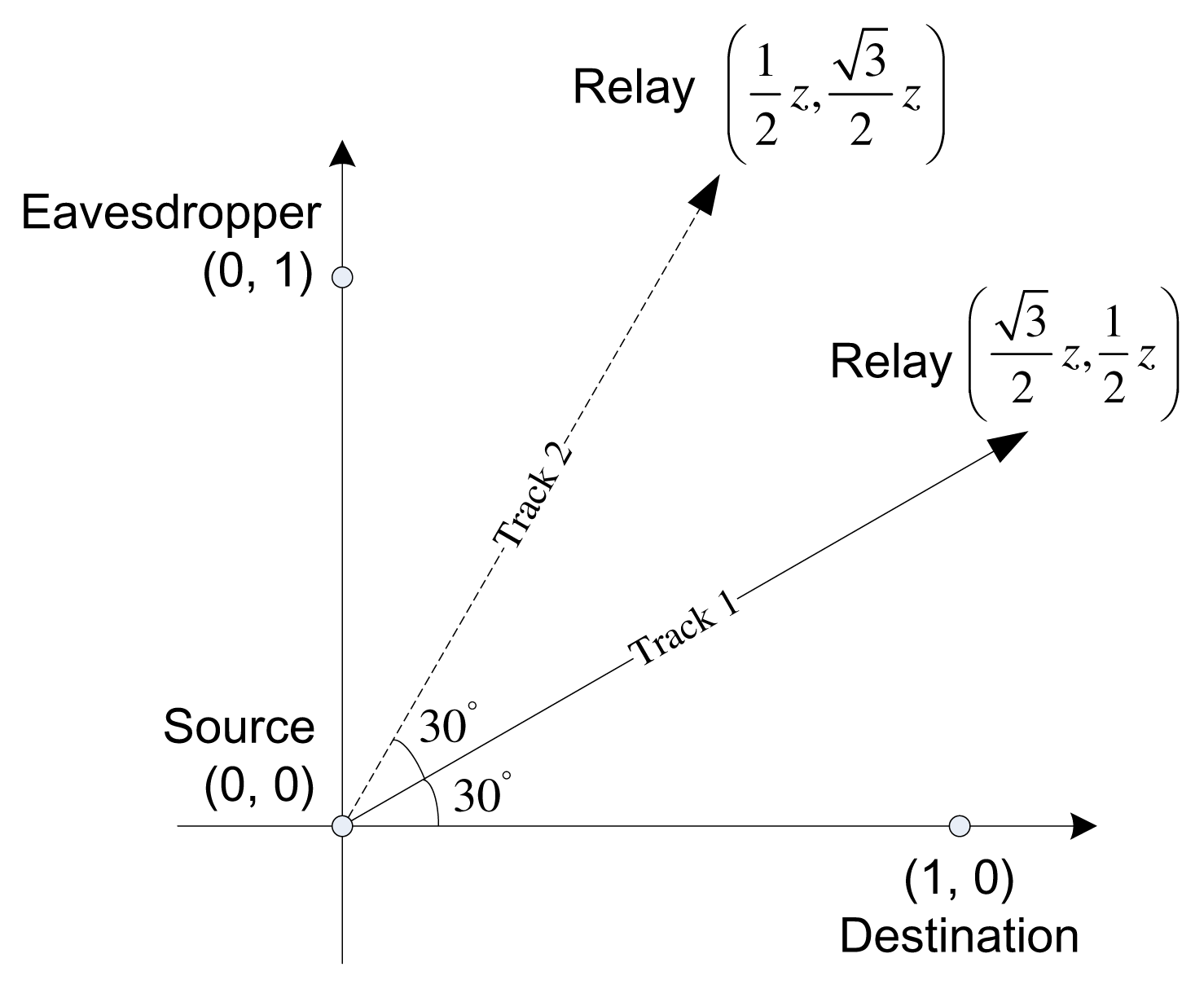
In this subsection, we will provide some numerical results to demonstrate the performance of the proposed hybrid cooperative scheme. Specifically, in the Gaussian relay-eavesdropper channel (10), the channel gain between node α ∈ {s, r} and node β ∈ {r, d, e} (α ≠ β) is . Here, dαβ is the distance between α and β and γ is the path loss exponent, which is set as γ = 2. Based on these definitions, we use the network geometry shown in Figure 3, where the source, the destination and the eavesdropper are located at (0,0), (1,0) and (0,1), respectively. In addition, the relay is located at ( ) in Track 1 and ( ) in Track 2, where z > 0. When the relay is in Track 1, it is nearer to the destination than to the eavesdropper; when the relay is in Track 2, it is nearer to the eavesdropper than to the destination. To show the performance of the proposed coding scheme, the DF scheme in [12], the partial DF scheme in [13], the NF scheme in [12] and the CJ scheme in [6] are taken to be the comparable ones. Note that when considering the network geometry in Figure 3, one will see that the DF scheme [12] achieves exactly the same secrecy rate as that of the partial DF scheme [13]. In computing the upper bound, following the same parameter setting in [12], we have used the upper bound in [12] (Theorem 1) using Gaussian inputs for the ease of computation. As discussed in [12], Gaussian inputs are not necessarily optimal for the upper bound.
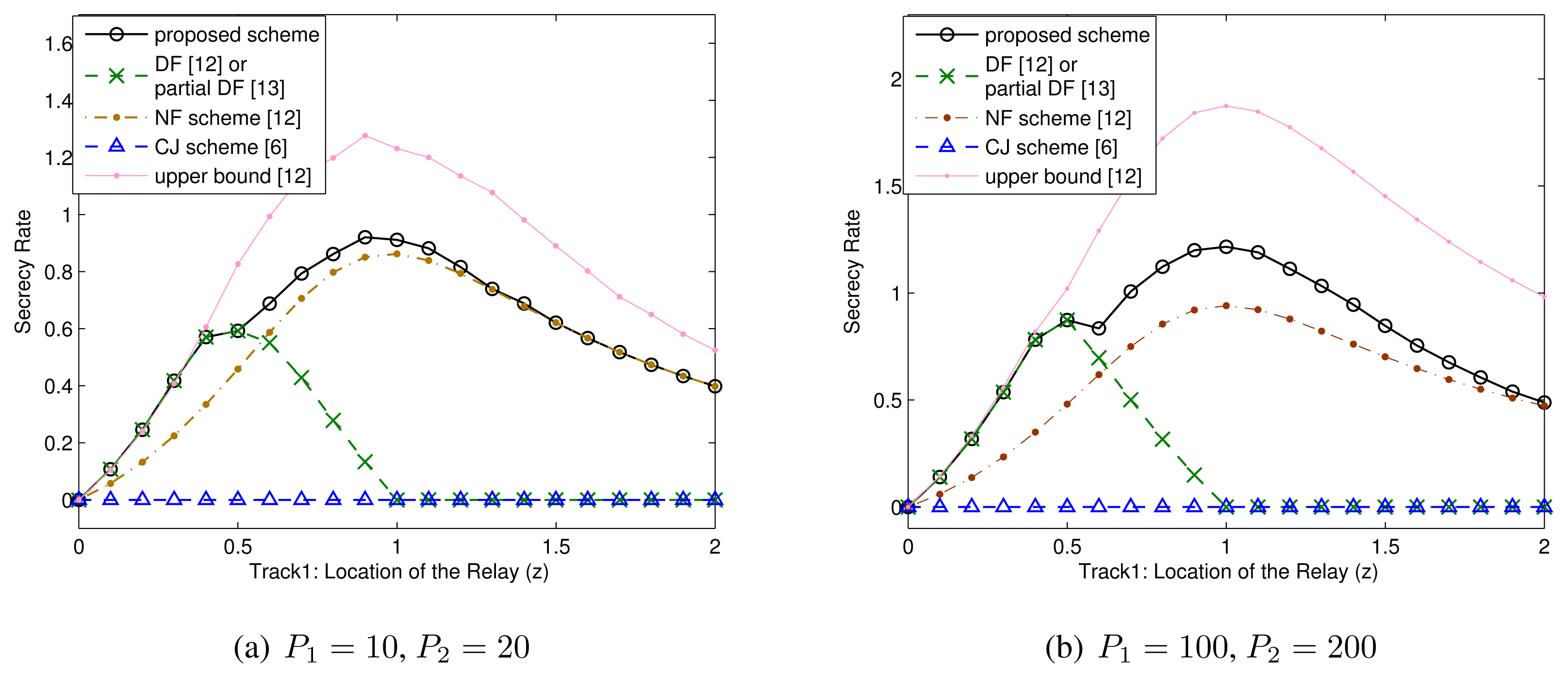
Figure 4 shows that achievable secrecy rates achieved the proposed scheme and the comparable ones for the case that the relay is in Track 1. In the first sub-figure, i.e., Figure 4a, we consider the moderate transmit power pair (P1, P2) = (10, 20). From this sub-figure, one can see that the DF scheme [12] (or the partial DF scheme [13]) can only perform well when the relay is very near to the source (i.e., z is small). However, the proposed hybrid cooperative scheme with artificial interference can still perform well when the relay is not near the source (i.e., z is large). When 0 < z < 1.3, the proposed scheme can achieve an exactly larger secrecy rate in comparison with the NF scheme [12]. Interestingly, the proposed scheme can still outperform the NF scheme when 1 < z < 1.3, which means that partially decoding the source message at the relay is useful, even if hsr < hse. This is because the interference at the relay can protect the transmissions from the source to the relay by confusing the eavesdropper. When z > 1.3, the proposed scheme reduces to the NF scheme, and the relay should not decode any source message in this case. In the second sub-figure, i.e., Figure 4b, we consider the high transmit power pair (P1, P2) = (100, 200). From this sub-figure, one can see that the performance gain between the proposed scheme and each comparable one is enlarged. This is because the performance of the proposed scheme can be greatly enhanced when the transmit powers at the source and the relay increase, as shown in Lemma 2 and Remark 6.
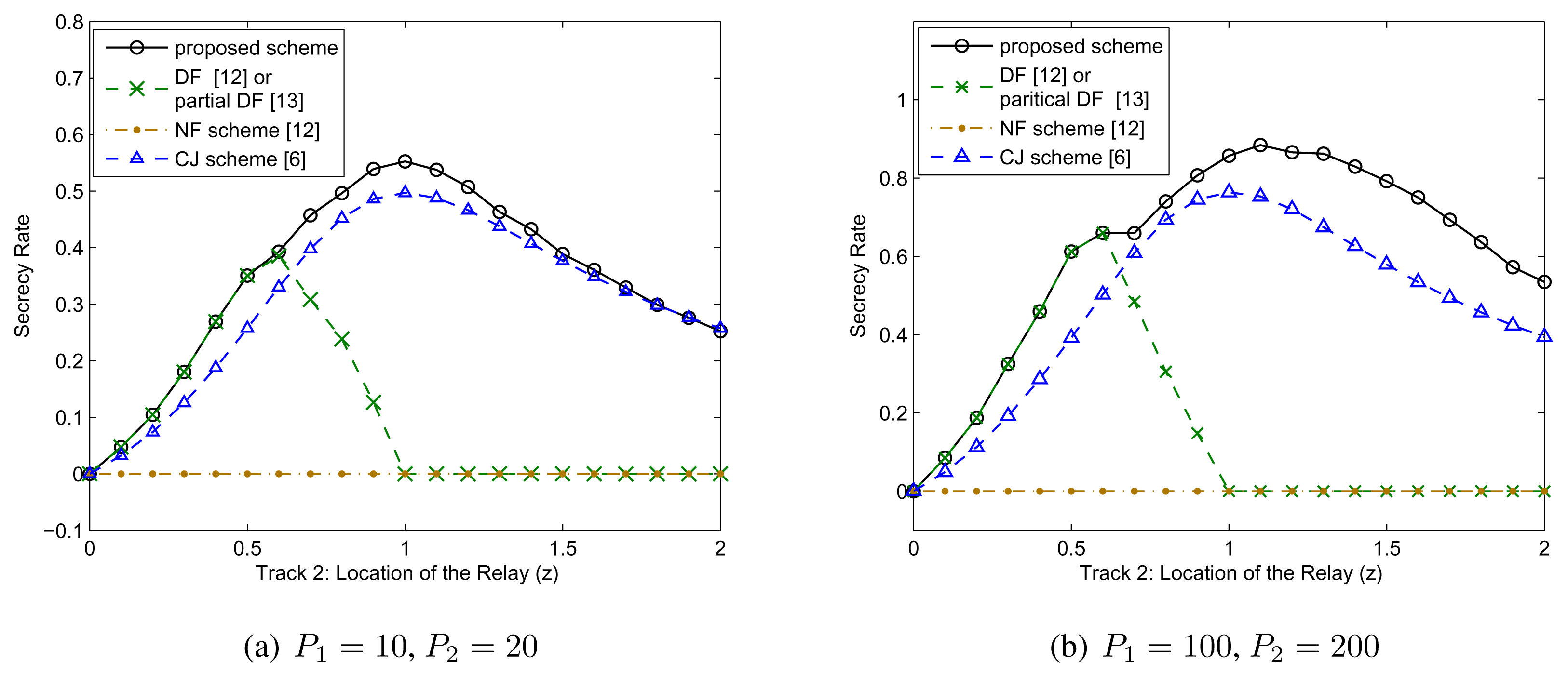
Figure 5 shows the achievable secrecy rates achieved by the proposed scheme and the comparable ones for the case that the relay is in Track 2. Figure 5a,b also considers the moderate power pair (P1, P2) = (10, 20) and the high power pair (P1, P2) = (100, 200), respectively. Since the relay is nearer the eavesdropper in Track 2, the NF scheme is invalid. In this case, the CJ scheme [6] can achieve a positive secrecy rate, since the artificial noise at the relay harms the eavesdropper more than it harms the destination. However, the achievable secrecy rate of the CJ scheme is bounded even at high transmit power, as shown in [14]. To the contrary, the achievable secrecy rate of the proposed scheme is unbounded at high transmit power, as shown in Equation (19) and Remark 6. This is mainly because the interference at the relay can protect the transmissions from the source to the relay by confusing the eavesdropper, as discussed in Remark 6. As a result, the proposed scheme outperforms the CJ scheme and the comparable ones, especially in the high power region, as shown in Figure 5a,b.
3.4. Comparison with the Secrecy Rate in [20]
Since it is intractable to compare the two secrecy rates achieved by the proposed scheme and the one in [20] in theory, in this subsection, some numerical examples will be illustrated to compare these two achievable secrecy rates. We will first prove that the CF relaying strategy is useless when considering the perfect secrecy rate. Since the random variables (V, U) in [20] have the same meaning as that of (U, V1) in this paper, (V, U) in [20] are replaced by (U, V1), respectively, for coherence. When considering the perfect secrecy rate, R1 = Re in Equation (17) in [20] and Re can be upper bounded as:
for some distribution p(u, v1, x1, x2, ŷ1, y, y1, y2) = p(u)p(v1|u)p(x1|v1)p(x2|u)p(ŷ1|y1, v1, x2) p(y, y1, y2|x1, x2), where (a) is due to Equation (18) in [20]; (b) is due to the Markov chain (Y, X1) → (Y1, X2, V1) → Ŷ1, which leads to the fact that:
From Equation (20), obviously we should set Ŷ1 = ∅︀, and the CF relaying strategy is useless. Now, the network geometry of Track 1 in Figure 3 is taken as an example to compare the proposed scheme and the one in [20]. To be fair, the random variables (U, V1, X1, X2) in Equation (20) are also set according to Equations (11)–(13).
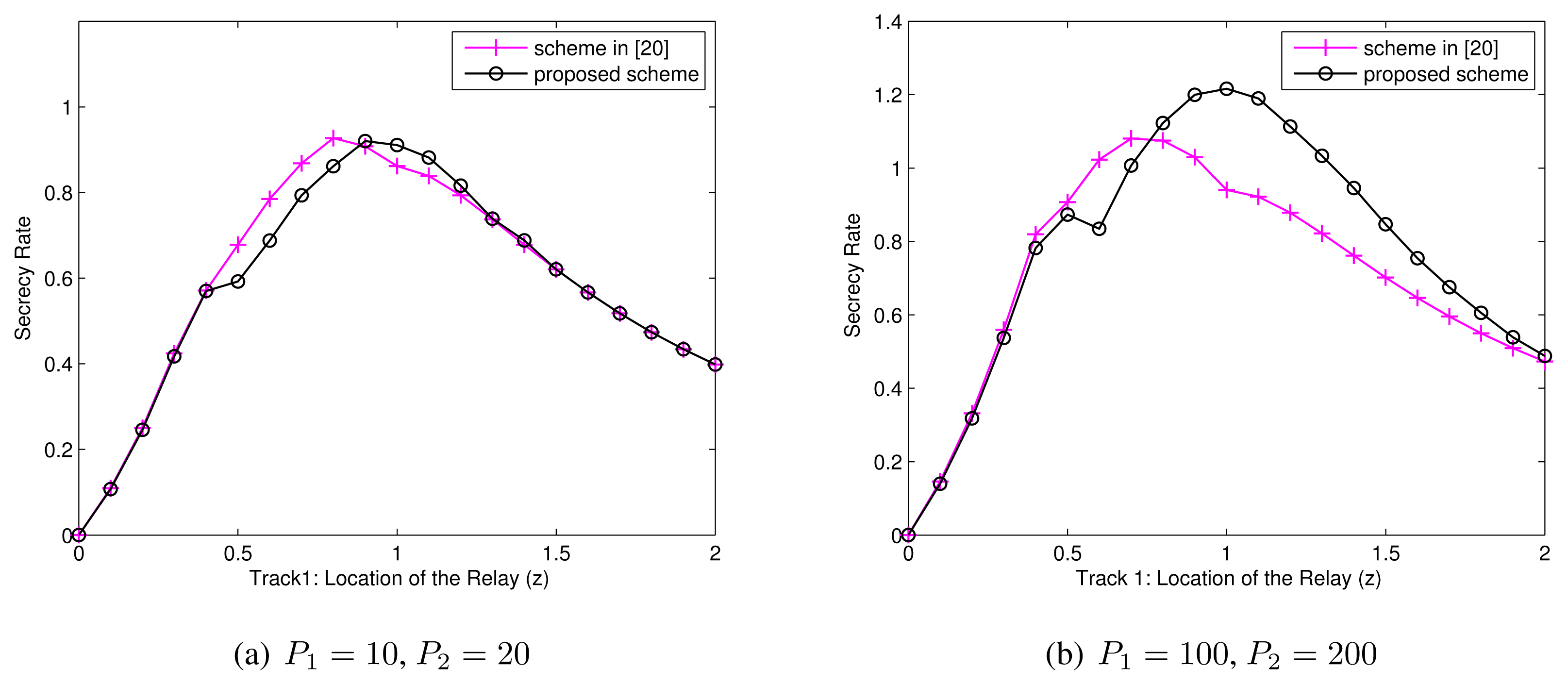
As shown in Figure 6a,b, the scheme in [20] outperforms the proposed scheme when the source-relay channel is strong (i.e., z is small), but the proposed scheme outperforms the scheme in [20] when the source-relay channel is weak (i.e., z is large). In other words, each of the two coding schemes has its own advantages, depending on the choices of z. This is mainly because different decoding strategies are utilized in this paper and [20]. Specifically, the scheme in [20] decodes the common part of the source messages (V1) after decoding the interference messages (X2) from the relay, which is beneficial for the receiver to decode the common part of the source message. When the source-relay channel is strong, such a scheme performs well, since most source messages should be allocated to the common part. To the contrary, the proposed scheme decodes these two messages in a reversed order, which is beneficial for the receiver to decode the the interference message. This implies that the proposed scheme can set the rate of the interference message larger to confuse the eavesdropper and, hence, performs better than the comparable one for a weak source-relay channel.
4. Proof of Theorem 1
4.1. Preliminary Results
In the following, we first give a useful lemma with respect to the equivalency of two mutual information.
Lemma 3
For a given joint distribution, p ∈ ℘, I(X2; Y2|U, X1) = I(X2; Y2|U, V1, X1).
Proof
Refer to Appendix B
Moreover, we define some parameters as follows:
Based on Lemma 3, in Equation (24) can be rewritten as:
The proof of the above equality will be provided in Appendix C.
4.2. Proof of Theorem 1
The proposed achievable scheme is based on the careful combination of the partial DF [18] scheme for the relay channel, the NF scheme [12] for the relay-eavesdropper channel and the random binning for the wiretap channel [2]. We first consider the random code generation as follows.
Codebook Generation
For a given distribution, p ∈ ℘, generate at random independent and identically distributed (i.i.d.) n-sequences, each according to . Then, randomly group these codewords into 2nR12 bins, each with codewords, and index them as , where wc,1 ∈ {1, …, 2nR12}, . For simplicity, let
For each un(w0), the relay generates at random 2nR2 i.i.d. n-sequences, each according to . Index them as , where w2 ∈ {1, …, 2nR2}.
For each un(w0), generate at random i.i.d. n-sequences, each according to . Then, randomly group these codewords into 2nR12 bins, each with codewords, and index them as , where w12 ∈ {1, …, 2nR12}, .
For each tuple (un(w0), ), generate at random i.i.d. n-sequences each according to . Then, randomly group these codewords into 2nR11 bins, each with codewords, and index them as , where w11 ∈ {1, …, 2nR11}, .
Encoding
The encoder structure of the proposed scheme is roughly illustrated in Figure 2.
At Block 1, the source sends and the relay sends , where w01 = (1, 1).
At Block b (2 ≤ b ≤ B − 1), the source wishes to send the new confidential message w1b ∈
= {1, …, 2nR1}. It first splits this message into two independent sub-messages, i.e., w1b = (w12b, w11b), where w12b ∈ {1, …, 2nR12}, w11b ∈ {1, …, 2nR11} and R1 = R12 + R11. Then, randomly choose some dummy messages,
and
, to be mixed with them, respectively, and the source sends the codeword,
, where
. For the relay node, it is assumed to already have a correct estimation of
at the end of Block b − 1 (refer to the decoding part), then it randomly selects a dummy message, w2b ∈ {1, …, 2nR2}, and sends
.
At Block B, the source sends , and the relay sends , where .
Decoding
At the end of Block b, assume that the relay has already decoded , which was transmitted at Block b − 1. Then, it will find a unique pair (ŵ12b,), such that
If there exist more than one or none such pairs, an error occurs. It is not difficult to prove that the error probability goes to zero, if the rates, R12 and , satisfy:
The destination performs backward decoding. At the end of Block b (2 ≤ b ≤ B − 1), assume that the destination has already correctly decoded at the end of Block b + 1. Then, the destination will perform separated decoding to decode w0b, w2b and (w11b,), respectively. First, it finds a unique ŵ0b, such that
The error probability goes to zeros if:
Second, knowing w0b, the destination finds a unique ŵ2b, such that
The error probability goes to zero, since we have fixed R2 to satisfy R2 < I(X2; Y |U, V1) in Equation (23).
Third, knowing w0b and w2b, the destination finds a unique pair (ŵ11b,), such that:
The error probability goes to zeros if:
Equivocation Computation
We let XBn denote the set, {Xn(1), Xn(2), …, Xn(B)}. Xbn and Xn(]b [) denote the set, {Xn(i), 1 ≤ i ≤ b}, and the set, {Xn(i), 1 ≤ i < b or b < i ≤ B}, respectively. The equivocation over the total B Markov blocks can be bounded as:
The first term in Equation (29) is:
The second term can be bounded as:
where (a) follows by the fact that conditioning does not increase entropy. (b) follows from the fact that is a Markov chain. Such a Markov chain is due to the memoryless channel and can be observed from encoding process in which depends on only through .
Furthermore, for ∀b ∈ [1 : B], we have:
and:
where (c), (d) and (e) can be obtained using the same approach in [10] (Lemma 3). According to the above two inequalities, in Equation (31) can be bounded as:
To bound the third term, , we will prove that the eavesdropper can correctly decode (UBn,) with the side information, . Note that (UBn,) is determined by the message tuple (w12b,, w11b,, w2b) for ∀b ∈ [1 : B]. Thus, with the knowledge of W1(b) = w1b = (w12b, w11b) for ∀b ∈ [1 : B], the eavesdropper only needs to utilize backward decoding to decode ( , w2b,) at the end of Block b. Then, the eavesdropper can determine the message tuple (w12b,, w11b,, w2b) for ∀b ∈ [1 : B]. Let denote the average error probability of decoding ( , w2b,) for ∀b ∈ [1 : B] at the eavesdropper. The following lemma shows that is arbitrarily small.
Lemma 4. for sufficiently large n.
Proof
Refer to Appendix D.
Then, based on Fano’s inequality, it can be easily obtained that:
Hence, the third term in Equation (29) can be bounded as:
Now, according to the definitions in Equations (22)–(24) and by combining Equation (29) with Equations (30), (34) and (35), we have:
Let B →∞; the secret constraint is satisfied. Furthermore, according to Equations (26), (27) and (28), one can verify that the secrecy rate, R11(p) + R12(p) (defined in Equations (4) and (5)), is achievable by using the conversion of in Equation (25).
5. Conclusions
In this paper, we have proposed a hybrid cooperative coding scheme, which enables the relay to integrate the explicit cooperation strategy and the implicit cooperation strategy by forwarding source messages and additional interference at the same time. The basic idea is to combine the partial DF scheme [18], the NF [12] scheme and random binning [2]. The derived achievable secrecy rate shows that the proposed scheme outperforms some existing works. Then, the achievable secrecy rate is extended to the memoryless Gaussian channel using Gaussian codebooks, and a power policy is developed in the high power region. The result shows that the secrecy rate achieved by the proposed scheme is sufficiently large in the high power region, even if the source-relay link is weak. This is benefited from the fact that the transmissions from the source to the relay can be protected by the interference generated at the relay. Finally, some numerical results have been carried out to demonstrate that the proposed scheme outperforms the comparable ones, especially in the high power region.
Due to the advantages of the hybrid cooperative coding schemes, a future direction of interest is to study the hybrid cooperative coding schemes for more complicated scenarios with more than one confidential message. One can also design more excellent coding schemes, such as combing the channel prefixing techniques [3] and utilizing a more general joint decoding approaches. For simplicity, the proposed scheme uses a separated decoding approach to decode the interference messages, as shown in Section 4, but it is worth pointing out that coding schemes associated with joint decoding may further enhance the security level.
Acknowledgment
The work of Peng Xu and Xuchu Dai was supported by the National Basic Research Program of China (973 Program: 2013CB329004), the National Natural Science Foundation of China (mo. 61271272) and the Intercollegiate Key Project of Nature Science of Anhui Province under Grant No. KJ2012A283. The authors are also grateful to the anonymous reviewers for their helpful suggestions.
Appendix
A. Proof of Lemma 2
A.1. Simplified Expression of the Secrecy Rate
Here, we will simplify the expression of the secrecy rate in Equation (15). Specifically, let: P̄1 = |hsd|2P1, and P̄2 = |hre|2P2, . Then, the power allocation set in Equation (14) becomes:
Using the above conversions and the definitions of a, b, c in Lemma 2, for a Ā ∈
 ,
and
in Equations (16) and (17) can be rewritten as:
,
and
in Equations (16) and (17) can be rewritten as:
A.2. Proof of Lemma 2
From Equation (39), obviously, we have:
When P1 = P2 = P → ∞, let and with 0 ≤ β, γ, η ≤ 1. Then, the three terms at the right-hand of Equation (40) can be upper bounded as:
where Equation (41) holds, since it is maximized by and .
Now, for r = ±1 and ∀Ā ∈
, combining Equation (40) with the above three relationships, we have:
where Equation (46) holds, since η = 0 maximizes Equation (45); Equation (47) holds, since maximizes Equation (46). This can be seen from the following proof steps.
If 0 ≤ γ ≤ β ≤ 1, we have:
where “≤” in both (a) and (b) can be replaced by “=” by choosing in this case.
On the other hand, if 0 ≤ β ≤ γ ≤ 1, we have:
where “≤” in both (c) and (d) can be replaced by “=” by choosing in this case.
In addition, according to Equation (38) and [14] (Lemma 2), becomes a constant when P →∞, i.e., . Therefore, the achievable secrecy rate in Equation (15) satisfies
On the other hand, one can verify that can be achieved by setting r = −1, and . Thus, the power policy in Lemma 2 is optimal, and this lemma has been proven.
B. Proof of Lemma 3
Before the proof of the equivalency, we first prove that V1 − (U, X1) − Y2 forms a Markov chain for a joint distribution, p ∈ ℘ (defined in Definition 1). Specifically,
where (a) is due to the two Markov chains: (V1, X1) − U − X2 and (U, V1) − (X1, X2) − Y2, as shown in Definition 1; (b) is due to the two Markov chains: X1 − U − X2 and U − (X1, X2) − Y2.
Based on such a Markov chain, we have:
C. Proof of Equation (25)
Before the proof steps, for a given p ∈ ℘, we first show that I(X2; Y2|U, X1) ≥ I(X2; Y2|U, V1) as follows:
where (a) is due to Lemma 3; (b) is due to the Markov chain: (V1, X1) − U − X2; (c) is due to the Markov chain: V1 − U − X2.
Now, from Equation (24), we can rewrite as:
According to the definition of R2 in Equation (23) and the relationship I(X2; Y2|U, X1) ≥ I(X2; Y2|U, V1) in Equation (52), can be further expressed as:
D. Proof of Lemma 4
With the knowledge of W1(b) = w1b = (w12b, w11b) for ∀b ∈ [1 : B − 1], the eavesdropper utilizes backward decoding to decode ( , w2b,) at the end of Block b. Assume that the eavesdropper has correctly decoded at the end of Block b + 1; then, it first finds a unique , such that:
Since the eavesdropper knows w12b−1, it only needs to find a unique .
After decoding w0b, the eavesdropper finds a unique pair (ŵ2b,), such that:
Analysis of error probability
With out loss of generality, assume that the transmitted message tuple is at Block b. The decoding process discussed above contains the following error events:
E1: does not satisfy Equation (55) or satisfies Equation (55);
E2: does not satisfy Equation (56);
E31: satisfies Equation (56), where i ≠ 1.
E32: satisfies Equation (56), where j ≠ 1.
E33: satisfies Equation (56), where i, j ≠ 1.
Then, the average error probability at Block b can be upper bounded as:
Now, we will calculate each term in the Equation (57). According to Equation (22), since , it is not difficult to prove that P{E1} ≤ ∊1 for sufficiently large n. When occurs, the eavesdropper can correctly decode . In this case, it is obvious that , according to the asymptotic equipartition property (AEP) [21]. Next, we will calculate for κ = 1, 2, 3 according to the properties of the joint typicality [21].
where the last relationship is due to Lemma 3. Similarly, we have:
and:
Since we have set the rate pair (R2,) in Equations (23) and (24) to satisfy:
the probability of is arbitrarily small for ∀κ ∈ {1, 2, 3}, as long as n is sufficiently large.
Thus, in Equation (57) satisfies for sufficiently large n. Consequently, in Lemma 4 can be arbitrarily small, and this lemma has been proven.
Conflicts of Interest
The authors declare no conflict of interest.
- Author ContributionsAll the authors contributed to the design, analysis, numerical results and presentation of the paper. All the three authors discussed, read and approved this manuscript.
References
- Shannon, C. Communication theory of secrecy systems. Bell Syst. Tech. J 1949, 28, 656–715. [Google Scholar]
- Wyner, A. The wire-tap channel. Bell Syst. Tech. J 1975, 54, 1355–1387. [Google Scholar]
- Csiszár, I.; Körner, J. Broadcast channels with confidential messages. IEEE Trans. Inf. Theory 1978, IT-24, 339–348. [Google Scholar]
- Chen, Y.; Han Vinck, A. Wiretap channel with side information. IEEE Trans. Inf. Theory 2008, 54, 395–402. [Google Scholar]
- Dai, B.; Luo, Y. Some New Results on the Wiretap Channel with Side Information. Entropy 2012, 14, 1671–1702. [Google Scholar]
- Tekin, E.; Yener, A. The general Gaussian multiple-access and two-way wiretap channels: Achievable rates and cooperative jamming. IEEE Trans. Inf. Theory 2008, 54, 2735–2751. [Google Scholar]
- Xu, P.; Ding, Z.; Dai, X. Rate Regions for Multiple Access Channel with Conference and Secrecy Constraints. IEEE Trans. Inf. Forensics Secur 2013, 8, 1961–1974. [Google Scholar]
- Liang, Y.; Poor, H. Multiple-access channels with confidential messages. IEEE Trans. Inf. Theory 2008, 54, 976–1002. [Google Scholar]
- Liu, R.; Maric, I.; Yates, R.; Spasojevic, P. The discrete memoryless multiple access channel with confidential messages. Proceedings of 2006 IEEE International Symposium on Information Theory, Seattle, WA, USA, 9–14 July 2006; pp. 957–961.
- Liu, R.; Maric, I.; Spasojevic, P.; Yates, R. Discrete memoryless interference and broadcast channels with confidential messages: Secrecy rate regions. IEEE Trans. Inf. Theory 2008, 54, 2493–2507. [Google Scholar]
- Ekrem, E.; Ulukus, S. Secrecy in cooperative relay broadcast channels. IEEE Trans. Inf. Theory 2011, 57, 137–155. [Google Scholar]
- Lai, L.; El Gamal, H. The relay-eavesdropper channel: Cooperation for secrecy. IEEE Trans. Inf. Theory 2008, 54, 4005–4019. [Google Scholar]
- Vaneet, A.; Lalitha, S.; Robert, A. C.; Vincent, H. P. Secrecy capacity of a class of orthogonal relay eavesdropper channels. EURASIP J. Wirel. Commun. Netw 2009, 2009. [Google Scholar] [CrossRef]
- Tang, X.; Liu, R.; Spasojevic, P.; Poor, H. Interference Assisted Secret Communication. IEEE Trans. Inf. Theory 2011, 57, 3153–3167. [Google Scholar]
- Awan, Z.H.; Zaidi, A.; Vandendorpe, L. Multiaccess Channel with Partially Cooperating Encoders and Security Constraints. IEEE Trans. Inf. Forensics Secur 2013, 8, 1243–1254. [Google Scholar]
- Oohama, Y. Relay channels with confidential messages 2007. arXiv:cs/0611125 [cs.IT].
- He, X.; Yener, A. Cooperation with an untrusted relay: A secrecy perspective. IEEE Trans. Inf. Theory 2010, 56, 3807–3827. [Google Scholar]
- Cover, T.; Gamal, A. Capacity theorems for the relay channel. IEEE Trans. Inf. Theory 1979, 25, 572–584. [Google Scholar]
- Awan, Z.H.; Zaidi, A.; Vandendorpe, L. Secure communication over parallel relay channel. IEEE Trans. Inf. Forensics Secur 2013, 7, 359–371. [Google Scholar]
- Sonee, A.; Salimi, S. A new achievable rate-equivocation region for the relay-eavesdropper channel. Proceedings of 18th Iranian Conference on Electrical Engineering (ICEE), Isfahan, Iran, 11–13 May 2010; pp. 188–193.
- Cover, T.; Thomas, J. Elements of Information Theory, 2nd ed; Wiley: New York, NY, USA, 2006. [Google Scholar]


© 2014 by the authors; licensee MDPI, Basel, Switzerland This article is an open access article distributed under the terms and conditions of the Creative Commons Attribution license (http://creativecommons.org/licenses/by/3.0/).
Share and Cite
Xu, P.; Ding, Z.; Dai, X. A Hybrid Cooperative Coding Scheme for the Relay-Eavesdropper Channel. Entropy 2014, 16, 1819-1841. https://doi.org/10.3390/e16031819
Xu P, Ding Z, Dai X. A Hybrid Cooperative Coding Scheme for the Relay-Eavesdropper Channel. Entropy. 2014; 16(3):1819-1841. https://doi.org/10.3390/e16031819
Chicago/Turabian StyleXu, Peng, Zhiguo Ding, and Xuchu Dai. 2014. "A Hybrid Cooperative Coding Scheme for the Relay-Eavesdropper Channel" Entropy 16, no. 3: 1819-1841. https://doi.org/10.3390/e16031819