1. Introduction
Compression refrigeration and heat pump systems consume a large amount of high-grade energy. On the other hand, hydrochlorofluorocarbons (HCFCs) that are widely used refrigerants at present are subject to total phase-out in a scheduled time-frame due to their potential harm to the environment. However, the probable substitute refrigerants, such as carbon dioxide (CO2) or hydrofluorocarbons (HFCs), are often thermodynamically less efficient compared with the conventional HCFC-based systems. In this situation, the issue of energy-savings in refrigeration-related applications has been of growing widespread concern over the past decades.
The basic vapor compression refrigeration cycle is composed of a compressor, a condenser, a throttling valve and an evaporator. In these conventional cycles, the kinetic energy of the liquid flow is dissipated to the refrigerant as the friction heat during the isenthalpic expansion, and energy available in the high pressure refrigerant is not recovered. The validated method to reduce this loss is based on replacing the throttling valve with a two-phase expander. Yang
et al. [
1] thermodynamically found that the replacement of throttling valve with an expander in the transcritical CO
2 cycle can increase the COP and exergy efficiency by 33% and 30%, respectively. The two values become lower when HCFCs/HFCs are used as refrigerants, but the gain is still interesting to enhance the overall efficiency of the system, especially for large capacity systems, where it is not only evaluated in a relative value but also in an absolute value. In recent years, various expander concepts and prototypes have been investigated and developed for the transcritical CO
2 refrigeration cycles as well as subcritical refrigeration systems with traditional HCFCs/HFCs as refrigerants, e.g., piston [
2,
3], rolling/swing piston [
4–
7], vane [
8–
10], scroll [
11–
13], and screw [
14,
15], which have demonstrated the viability of this approach.
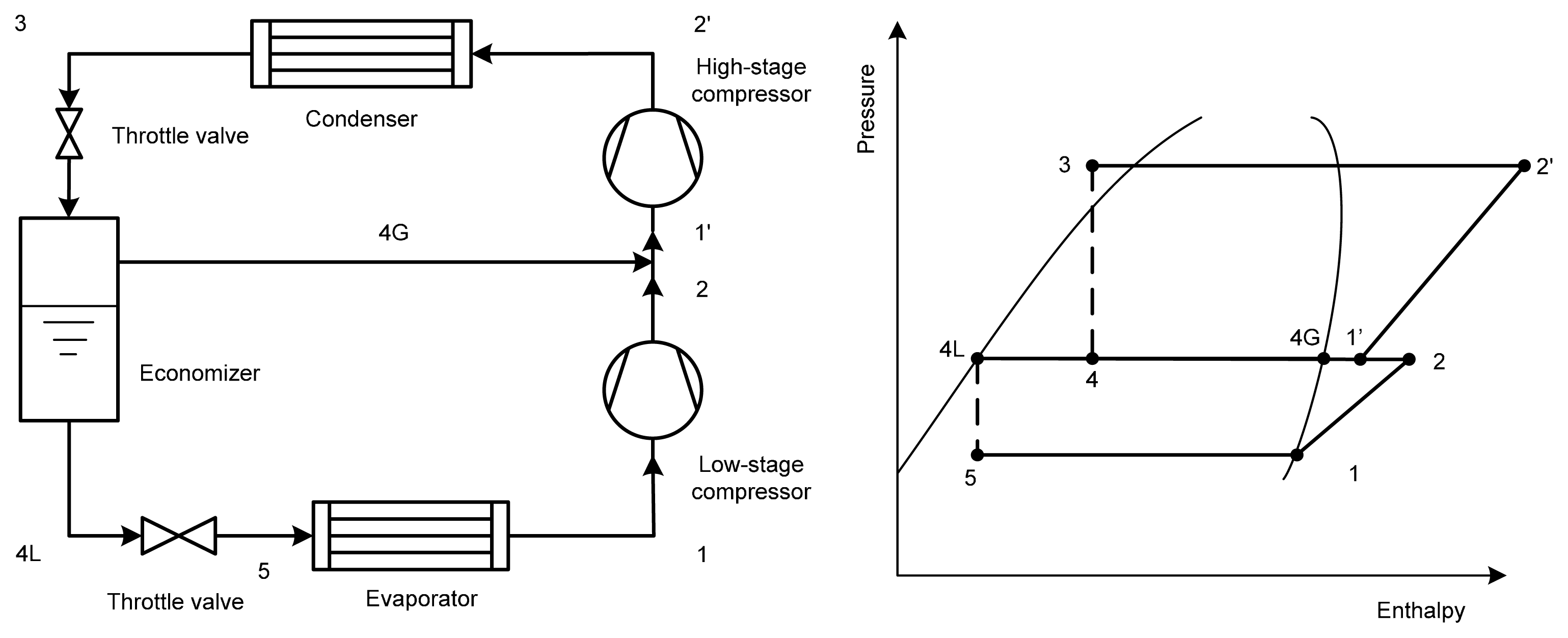
The economizer is another device used to decrease the throttling loss and improve the cycle efficiency. The schematic and the P-h diagram of the economizer cycle are shown in
Figure 1. Thus further improvement in the COP is expected to be obtained for the expander-economizer hybrid cycle. However, relatively little literature is available on the performance of the hybrid cycle. To the best knowledge of the authors, only Binneberg
et al. [
16] have performed a theoretical analysis on the CO
2 expander-economizer hybrid cycle and reported a 5–8% and a 60% increase in COP over the expander cycle and the basic cycle, respectively.
The impulse turbo expander (ITE) is an attractive option owing to the separation between the expansion process and the kinetic energy recovery process.
Figure 2 displays the configuration of the conventional ITE. The expander is comprised of two basic parts: a nozzle and a disk with blades. The nozzle converts the potential pressure energy of refrigerant into kinetic energy. The jet from the nozzle impinges blades and propels the disk to rotate, which generates mechanical work on the shaft. The working fluid is directed to the nozzle by the inlet and drained away by the outlet.
Figure 3 shows a schematic and the corresponding P-h diagram of the vapor compression refrigeration cycle with the conventional ITE.
Some researchers have investigated the performance of the conventional ITE in the refrigeration cycle shown as
Figure 3. Hays and Brasz [
17] designed an axial flow ITE applied to a 1760 kW centrifugal chiller using R134a as the working fluid and predicted that the overall ITE isentropic efficiency was between 50% and 55%, which resulted in 5.9%–10.0% reduction of the compressor power. Cho
et al. [
18] tested an axial ITE in the R134a refrigeration system with the maximum cooling capacity of 32.7 kW, and the reported maximum efficiency was 15.8%. He
et al. [
19] developed a Pelton-type ITE which was tested in the R410A domestic refrigeration system. The expander demonstrated a maximum isentropic efficiency of 32.8% under the experimental conditions. By applying the expander, the maximum increase of 5.4% in COP was obtained under the testing conditions. A radial outflow ITE was prototyped and tested by Tøndell [
20] for mobile air conditioning systems using CO
2 as the refrigerant. However, the expander exhibited low efficiency.
The conventional ITE and the corresponding refrigeration cycle have not been sufficiently efficient for a number of problems. Sakata
et al. [
21] discussed that the level of the liquid gathered in the bottom of the housing was generally so high that it submerged the lower part of the disk, and that the large additional friction loss was generated between the disk and the gathered liquid during the running process as well as at the starting moment of the refrigeration cycle, which lowered the conventional ITE performance. Furthermore, they suggested a new ITE, where a refrigerant liquid receiving section and a refrigerant vapor discharging outlet were employed. The embodiment of the ITE in a refrigeration cycle was described, but the performance of the proposed cycle was not investigated theoretically or experimentally.
Based on Sakata
et al.’s research [
21], an improved ITE and the corresponding cycle are presented in this paper. The proposed cycle is intrinsically an expander-economizer hybrid cycle. The exergy analysis of the proposed cycle has been carried out according to the first and second laws of thermodynamics, and the performance of the proposed cycle is compared with that of the conventional ITE refrigeration cycle, the traditional economizer cycle and the basic cycle.
2. The Improved Impulse Turbo Expander and the Corresponding Cycle
Figure 4 shows the configuration of the improved ITE. Compared with the conventional ITE, the following improved designs are suggested:
- (1)
A liquid accumulator is provided in the lower part of the housing to collect the liquid working fluid which is fed to the evaporator through outlet 1 arranged at the bottom of the accumulator. Thus if the volume of the accumulator is appropriately determined, the liquid working fluid can remain at a constant level in the accumulator so as not to get in touch with the disk of the expander.
- (2)
Another outlet (outlet 2), through which the saturated flash vapor is discharged, is provided at the upper part of the housing and communicates with the room inside the housing.
The schematic and the corresponding P-h diagram of the vapor compression refrigeration cycle with the improved ITE are presented in
Figure 5. The cycle is comprised of two compressors, a condenser, an evaporator, an ITE and an expansion valve. The refrigerant vapor leaving the evaporator (1) and enters the low-stage compressor, where it is compressed to an intermediate pressure (2). Then it is mixed with the refrigerant vapor (4G) discharged from outlet 2 of the ITE. The resulting mixed superheated vapor (1′) is sent to the high-stage compressor and further compressed to the condensing pressure (2′). The high temperature refrigerant is then discharged to the condenser and cooled to state 3 in the condenser. The high pressure liquid refrigerant exiting the condenser (3) enters the ITE nozzle and expands to a two-phase jet at an intermediate pressure (4). The jet impinges blades and propels the disk to rotate, which generates mechanical work on the shaft. At the same time, the liquid and the vapor phases are separated. The saturated vapor (4G) is directed through outlet 2 to the outlet of the low-stage compressor, while the liquid (4L) gathering in the accumulator is further depressurized to pressure Pe (5) through a small-pressure-drop throttle valve. Then the working fluid is boiled out in the evaporator producing a cooling action on the objects to be cooled and this finishes the cycle.
Compared with the traditional ITE and the corresponding cycle, the defect of disk contact with the liquid working fluid is avoided, and the corresponding loss can also be reduced in the running process as well as at the moment of starting the refrigeration cycle. Consequently, improvements of ITE efficiency and stabilization of the operation of the refrigeration cycle are expected to be gained. In the new cycle, the ITE not only acts as an expansion device with work extraction, but also serves as an economizer with vapor injection. Thus the performance of the refrigeration cycle is expected to be improved owing to the dual positive effects.
The rotor consists of three components: the disk, the blades, and the shaft. All components generate friction force with the fluid. This causes the friction loss, which according to Tondell [
20] can be evaluated by:
where the shaft friction loss is neglected due to the negligible proportion in the whole friction losses, k1 denotes the disk friction coefficient, k2 is an empiric coefficient taking into account the influence of the rotor geometrical shape, H is the blade height. ρ is the fluid density.
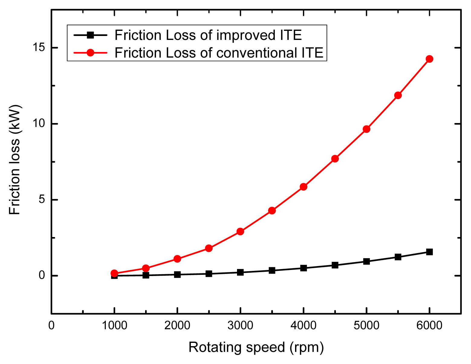
The friction losses comparison of the conventional ITE and the improved ITE are illustrated in
Figure 6. The Rotor’s geometrical parameters are from reference [
17]. The calculation condition is that the temperature is 5 °C. The inner space of the conventional ITE is assumed to be filled with the liquid-gas refrigerant whose quality is 0.2, whereas the inner space of the improved ITE is supposed to be filled with the gas refrigerant. It is can be seen that the friction loss of the improved ITE is greatly reduced compared with the conventional ITE, especially at high rotation speed. For the ITE in [
17], the tested optimum rotating speed is about 4000 rpm. The isentropic expansion work is about 35 kW for a 1760 kW chiller with R134a as working fluid. It can be seen from
Figure 6 that the reduction in friction loss is about 7.0 kW when the rotating speed is 4000 rpm. This implies that an increase of 20% in the isentropic efficiency can be attained for the improved ITE compared with the conventional ITE owing to the reduction of the friction loss of the rotor. The highest ITE isentropic efficiency is 55% according to Hays and Brasz [
17]. Thus the isentropic efficiency of the improved ITE can attain 75%.
3. Thermodynamic Modeling
This section provides descriptions of the component and the system modeling. To simplify the theoretical model of the cycle, the following assumptions are made:
- (1)
There are no pressure losses in pipes and heat exchangers.
- (2)
The small difference among the intermediate pressure, the discharge pressure of the low-stage compressor and the suction pressure of the high-stage compressor is negligible.
- (3)
The vapor stream and the liquid stream exiting the ITE are assumed to be saturated.
- (4)
The exiting working fluid of the evaporator is saturated vapor.
- (5)
The ITE and the compressor are treated adiabatically.
- (6)
The numerical simulation modeling of the cycle is based on one unit of the working fluid at the inlet of the ITE.
- (7)
The work output of the ITE is used to offset the power required by the compressor [
22–
24]. The efficiency for converting the ITE output work to the compressor power is considered to be included in the isentropic efficiency of the ITE.
- (8)
The vapor and liquid separation efficiencies in the turbine and the economizer are negligible.
3.1. Energy Analysis
The working fluid from the condenser enters the ITE and expands to the intermediate pressure with the ITE efficiency defined as:
The work output of the ITE is given as:
The fraction of vapor refrigerant discharged from outlet 2 of the ITE can be determined as:
The cooling effect of the cycle can be calculated as follows:
The isentropic efficiency of the low-stage compressor is defined as:
The compression work of the low-stage compressor is:
The inlet enthalpy of the high-stage compressor can be determined by applying the mass and energy conservation equations at the point of mixing:
The isentropic efficiency of the high-stage compressor is defined as:
The compression work of the high-stage compressor is:
The heat transfer rate of the condenser is:
The COP of the refrigeration cycle with the improved ITE cycle is calculated as:
3.2. Exergy Analysis
The specific exergy of the refrigerant can be evaluated as:
For Q at constant temperature T, the heat exergy rate ExQ can also be calculated by:
Exergy loss equations for compressors, condenser, ITE, throttle valve and evaporator are given as follows:
For compressors:
For the condenser:
For the ITE:
For the throttle valve:
For the evaporator:
Therefore, the total exergy losses of the system are:
The exergy efficiency of the refrigeration cycle with the improved ITE can be expressed as:
Based on the theoretical model, the simulation program using EES software [
25] was developed to evaluate the performance of the proposed refrigeration cycle. The other three cycles can be easily calculated by thermodynamic analysis.
4. Results and Discussion
In this study, R134a is selected as the working fluid. Unless otherwise specified, the reference environment temperature is 303K [
26], the evaporating temperature is 5 °C, the condenser temperature is 45 °C, the subcooling degree of the condenser is taken to be 5 °C, the suction refrigerant vapor of the compressor is assumed to be saturated, the efficiency of the compressor is assumed to be 80%, the efficiencies of the conventional ITE and the improved ITE are assumed to be 55% [
17] and 75%, respectively.
In the typical two-stage refrigeration cycle, the intermediate pressure plays an important role in the optimization of the performance of the cycle. The system has the highest performance when operating at the optimum intermediate pressure, which is the square root of the condenser pressure times the evaporator pressure from the classical estimate, that is:
In this paper, the deviation in the intermediate pressure from the classical estimate is expressed as PR, which is the ratio of pint to pgm. Thus it can be stated as:
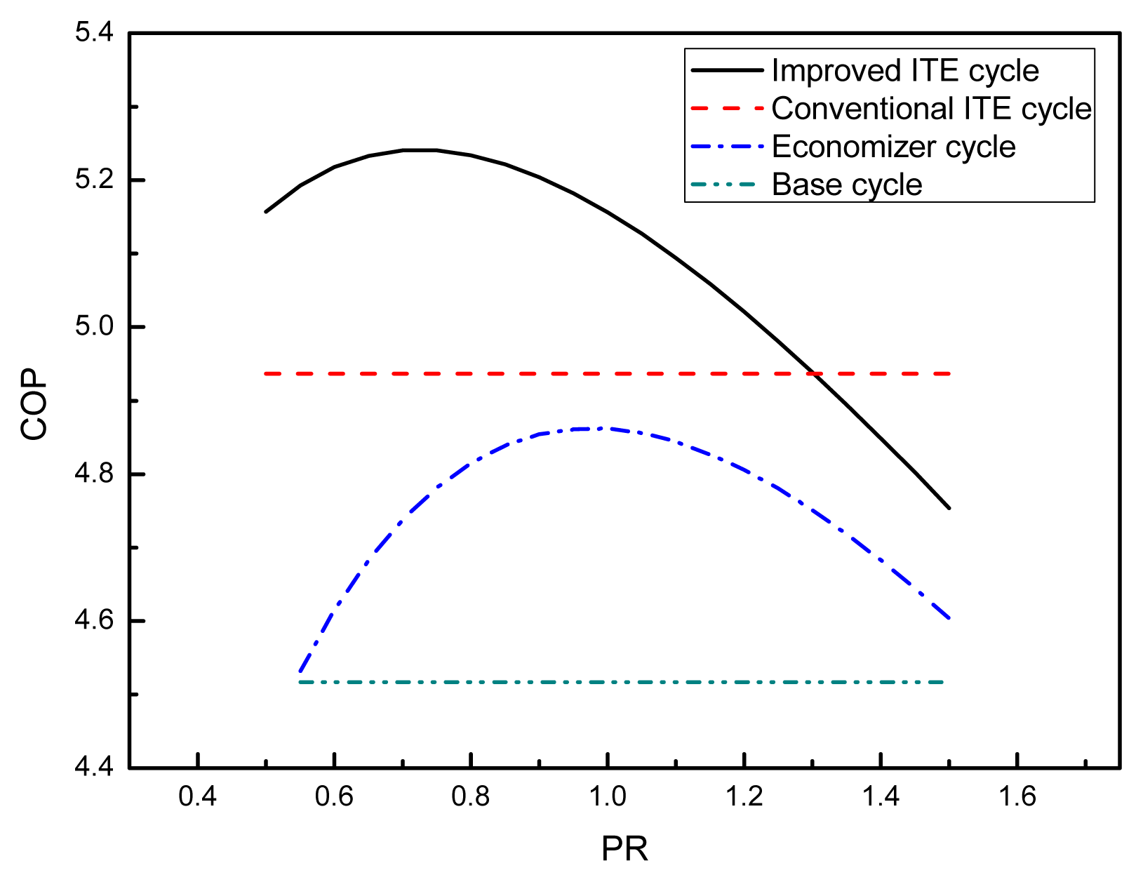
The role played by PR in COP for the investigated cycles is illustrated in
Figure 7. It can be seen that the value of COP first increases to the maximum and then decreases with the increment of pressure ratio (PR) for the improved ITE cycle and the economizer cycle. It is evident that the maximum COP is obtained at PR = 1 for the economizer cycle, which is consistent with the open published literatures. But this feature does not necessarily work for the improved ITE cycle. The optimum intermediate pressure of the improved ITE cycle is lower than
pgm. The COP value of the improved ITE cycle is higher than that of the conventional ITE cycle around the optimum intermediate pressure. Nevertheless, the improper selection of intermediate pressure may make the COP of the improved ITE cycle shift to lower values compared with the conventional ITE cycle.
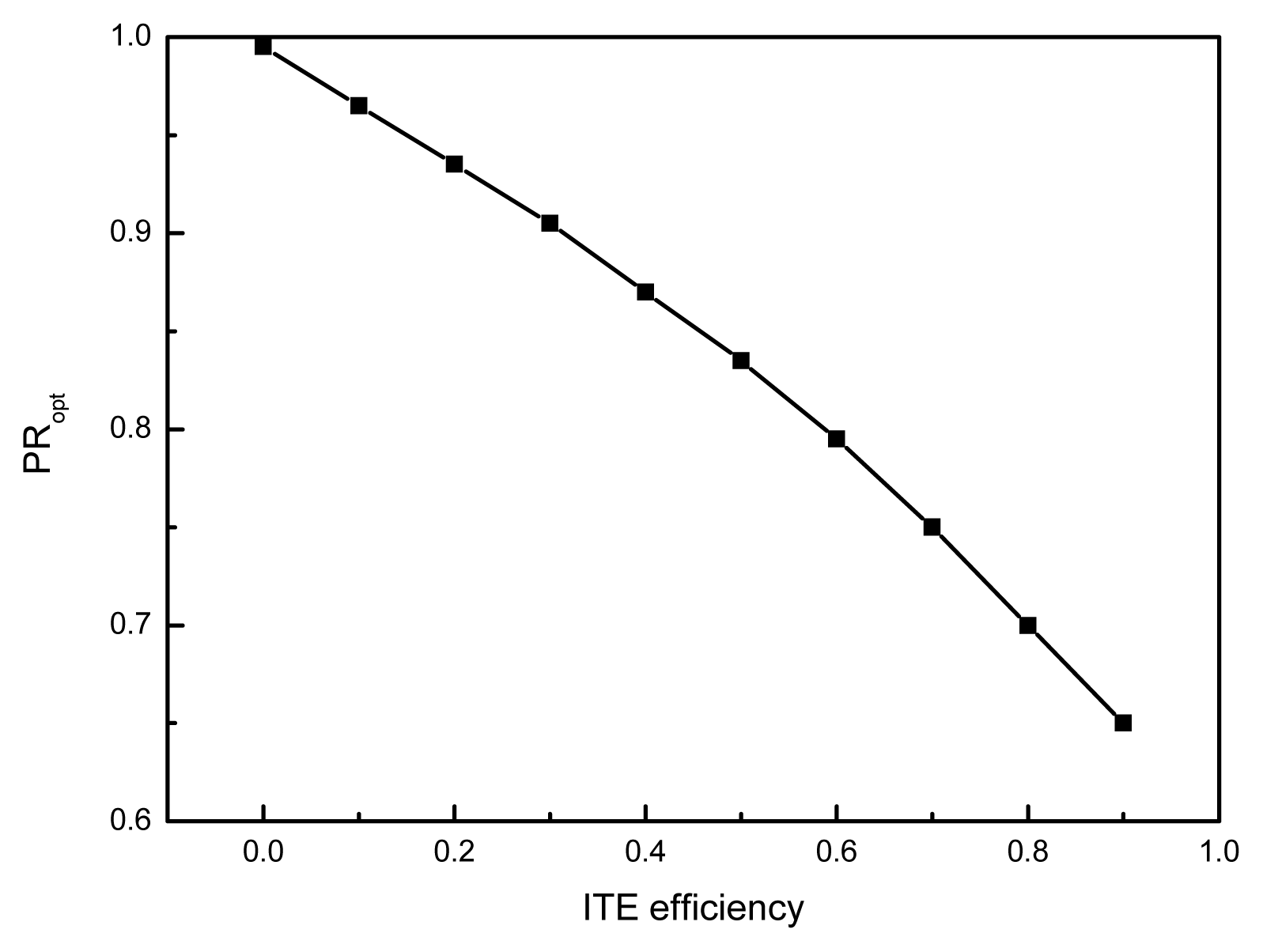
Based on the assumptions made in this paper, the optimum PR can be expressed by:
Figure 8 shows the effect of ITE efficiency on the value of PR
opt for the improved ITE cycle.
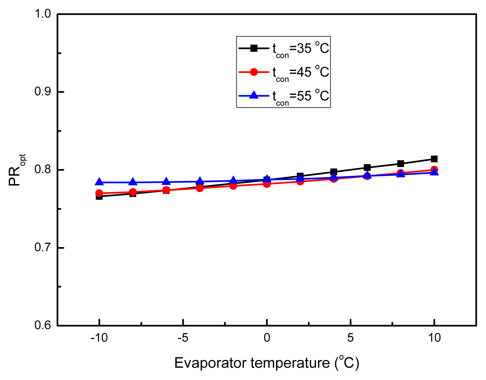
Figure 9 shows PR
opt versus the evaporator temperature under different condenser temperatures for the improved ITE cycle. It is observed from
Figure 8 that the value of PR
opt drops rapidly with the increase of the ITE efficiency. But the effects of the evaporator temperature and the condenser temperature seem to be relatively negligible compared with that of the ITE efficiency. A correlation for PR
opt(R
2 = 99.961%) in terms of the ITE efficiency based on a square polynomial fit of the simulated results is obtained:
Thus the following correlation for the optimum intermediate pressure can be expressed as:
The effect of ITE efficiency on the calculated system maximum COP for the investigated cycles is presented in
Figure 10. The results show that employments of the conventional ITE, the improved ITE or the economizer can improve the system COP compared with the basic cycle. The highest COP improvement is gained by the improved ITE cycle. As the ITE efficiency increases, the corresponding COPs of the conventional ITE cycle and the improved ITE cycle increase. Compared with the economizer cycle and the basic cycle, the improved ITE cycle shows a 7.8% and 16% increase in COP respectively when the ITE efficiency is 75%. We can also observe from
Figure 10 that the conventional ITE cycle has a lower COP than the economizer cycle if the ITE efficiency is lower than about 0.5.
Figure 11 displays the variation of the optimum COP values of the investigated cycles with the evaporator temperature under different condenser temperatures. It is apparent that along with the growth of the evaporator temperature or the decrease of the condenser temperature, the COPs of the investigated cycles increase. The increase in the COP is attributed to an increase in the refrigerating effect and a decrease in the input work of the cycle. For every working condition, the improved ITE cycle outperforms the other three cycles, showing approximately 1.4%–6.1%, 4.6%–8.3%, and 7.2%–21.6% COP improvement over the conventional ITE cycle, the economizer cycle and the basic cycle respectively. The improvement in the COP is owing to the employment of the improved ITE, which not only recovers power from the expansion process but also acts as an economizer with vapor injection. Both effects lead to an increase in the cooling effect and a decrease in the required power of the cycle. Thus, the overall result will be the improvement of the cycle COP. For heavier operating conditions, a growing advantage of the improved ITE cycle appears.
Figure 12 depicts the exergy efficiencies of the investigated cycles as functions of evaporating temperature for different condenser temperatures. It can be seen that the exergy efficiency decreases with the increase of the evaporating temperature and the condenser temperature. The improved ITE cycle performs better than the other three cycles and gives 1.4%–6.1%, 4.6%–8.3%, and 7.2%–21.6% increase in exergy efficiency against the conventional ITE cycle, the economizer cycle and the basic cycle respectively.
Figure 13 shows the exergy losses in different components of the four cycles. It indicates that the total exergy losses of the four cycles increase as the condensing temperature increases. This is because of the increase in temperature difference between the condenser and the evaporator. One can notice that the main irreversibility of the four cycles occurs in the condenser and the compressor. It is also interesting to note that the total exergy loss in the improved ITE cycle is lower than that in the other three cycles, showing approximately 5.4%–7.9%, 6.4%–7.0%, 14.5%–19.6% reduction over the conventional ITE cycle, the economizer cycle and the base cycle, respectively. This reduction is mainly due to the decrease in the expansion process.
In the real refrigeration systems, an expander generator can be added externally to the cycle. The power produced may be used directly to offset compressor power for electric motor drives or it can be used to service other loads. An estimate of the power generated for the improved ITE cycle is shown as a function of condenser temperature and refrigeration capacity for an evaporator temperature of 5 °C, assuming 75% efficiency of the ITE. The results are provided in
Figure 14. The power at 50 °C condenser temperature ranges from 20 kW for a 1000 kW chiller to 60 kW for a 3000 kW unit.


