1. Introduction
Energy has played an important role in industrial and economic progress throughout the history of mankind. In general, industrial equipments such as furnaces use electricity or gas as a fuel for their operation. Furnaces have various applications such as heat treatment, drying, polymerization, etc. On the other hand, industry requires continuous processes optimization and cost reduction. In addition, the energy consumption in this kind of equipment is high and besides fuel prices are constantly increasing.
An alternative is to replace conventional sources of energy used in these processes by renewable sources. The utilization of renewable energy offers a wide range of exceptional benefits like the fact almost none of them release gaseous or liquid pollutants during operation, a decrease in fossil fuel energy dependence, a decrease in the impact of electricity production and transformation, etc.
One of the most abundant resources on the surface of the Earth is sunlight. Solar energy is an option, which intent to solve this problem trough the development of new technologies. Many applications of solar thermal technologies can be found in the literature [
1,
2].
Solar energy applied to an air heating process is the alternative presented in the present paper. A solar collector is a special kind of heat exchanger that transforms solar radiant energy into heat. There are two important types: flat plate collectors and concentrating collectors; concentrating collectors are used for applications where it is desirable to deliver energy at high temperatures.
An exergy analysis (or second law analysis) has proven to be a powerful tool in simulated thermodynamic analyses of energy systems. In other words, it has been widely used in the design, simulation and performance evaluation of energy systems. The exergy analysis method is employed to detect and to evaluate quantitatively the causes of the thermodynamic imperfection(s) of the process under consideration [
3]. In the case of solar collector systems, from process analysis using the first and second law of thermodynamics a lot of information can be found. Flat plat collectors for heating water, or solar collectors for producing steam are some examples. Torchia presented an exergy analysis of a solar still, showing that irradiance is an important parameter in the performance of the equipment according to the thermodynamics [
4]. Most of the methodologies for energy and exergy analysis of solar thermal collectors are summarized by Kalogirou [
5]. Hepsbali also presented an overview of renewable energy sources [
6]. Bejan presented, in detail, a thermodynamic analysis of solar collectors [
7]. The exergetic analysis presented by Petela helps to calculate the exergy of inlet and outlet of solar cylindrical-parabolic collectors. The results show that the exergy efficiency is very low (~1%), although this study was done with water [
8].
Kavak and Akpinar presented an analysis of a flat solar collector for an air heating application. In that study they determined the energy and exergy efficiencies, along with assessment methodologies for the first and second law applied in flat solar collectors. The maximum values of efficiency are 82% for the first law and 44% for the second law [
9].
Thermoeconomic analysis is a tool to find the trade-off between input costs, including fuel costs and capital expenditures, and production cost. A thermoeconomic analysis can be performed based on energy and exergy analysis data, as well as the cost of the equipment, maintenance and operations used in the process.
Barranco
et al. presented a paper on thermoeconomic research. In that paper, the thermoeconomic optimization of an endoreversible solar driven heat engine was carried out by using finite-time/finite-size thermodynamic theory. The optimum performance and two design parameters were investigated so as to determine the best design parameters for a solar-driven heat engine [
10].
A thermoeconomic analysis developed for a three-step vertical tubular heater was presented by Marín-Gonzales. In this paper the thermoeconomic method was applied to find the optimal geometric design of a vertical tubular air heater, whose original design is widely used in boilers installed in sugar mills [
11].
A systematic and general methodology for defining and calculating exergetic efficiencies and exergy related costs in thermal systems, and how to conduct an evaluation of costs associated with all the exergy streams entering and exiting a system component. This methodology was proposed by Lazzaretto and Tsatsaronis [
12].
This document is presented due to the lack of information about the application of thermoeconomic analysis, processes in which the working fluid is air and the solar equipment is a parabolic trough collector. The aim of this paper is to present an thermoeconomic analysis based on the thermal and econonomic analysis of solar equipment taking into account the methodology used by Tsatsaronis [
12,
13]. This analysis focuses on the thermoeconomic evaluation of the parabolic trough collector as a substitute for the electrical resistance used in the process of heating the air inside a chamber. With this methodology, we determined the cost of the heat supplied to the fluid of work in the process. A parametric analysis was also developed to optimize the size of the solar collector. The analysis was realized taking into consideration meteorological data registered in Queretaro (Mexico) in recent years and data acquired at the site with a data acquisition system. These data were used to perform the thermoeconomical analysis of the prototype.
2. Experimental Section
The analysis was carried out taking into account the climatic conditions in the city of Queretaro, Mexico, located at latitude 100°23′34″degrees west and longitude 21°35′15″ degrees north and an altitude of 1820 meters above sea level. Marroquin reported the amount of solar radiation that reaches Querétaro, Mexico. This study from June 2006 to July 2007 provides solar radiation, temperature, and monthly average wind speed [
14]. With these data we have analyzed the prototype furnace from a theoretical point of view. A summary of these data is presented on
Table 1.
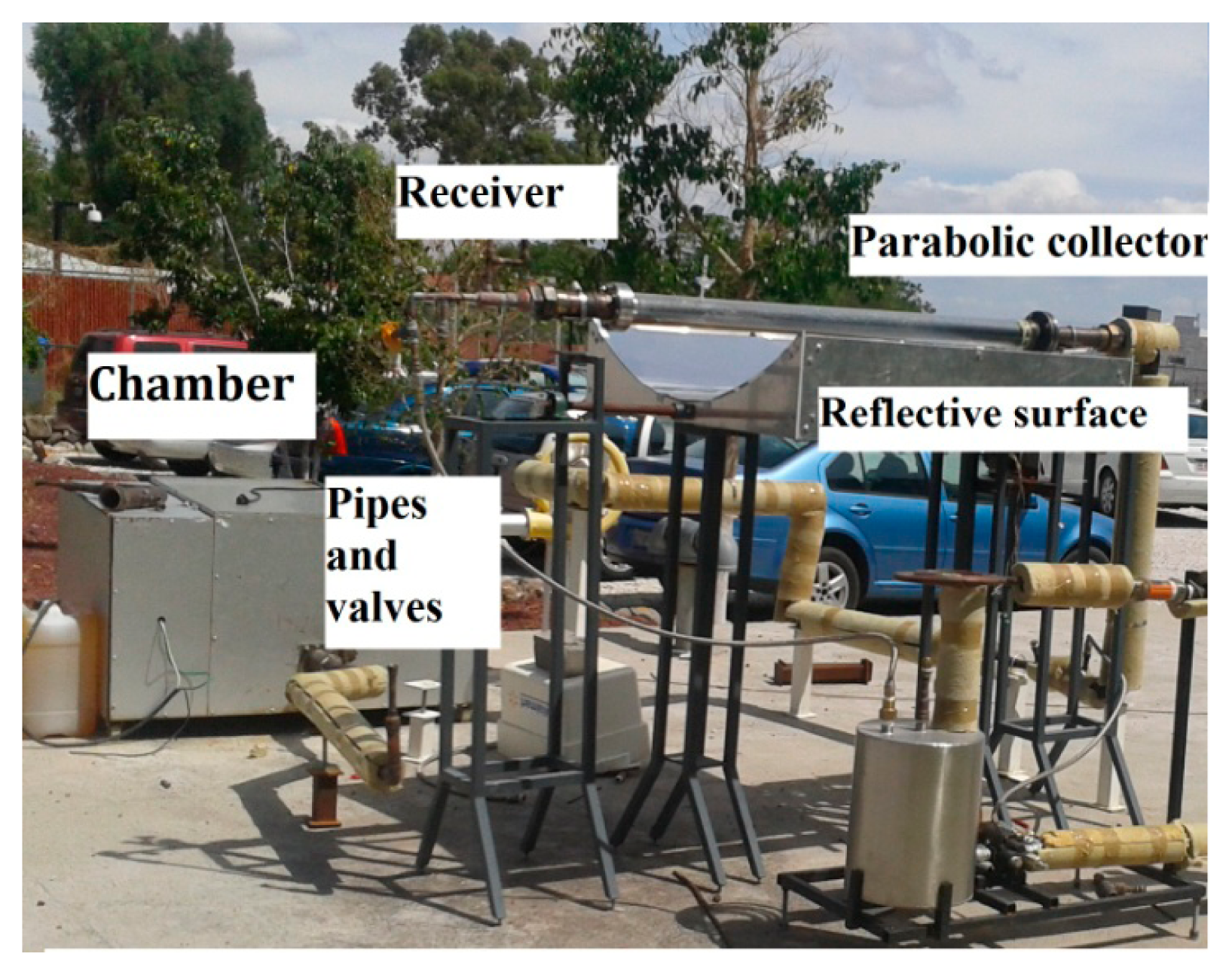
The solar prototype, shown in
Figure 1, consists of a convection heating chamber, a parabolic trough collector, an electrical heating system, pipes, and valves. Chamber dimensions are 0.5 m width, 0.5 m height and 1.0 m depth. The chamber is completely insulated with a high-temperature insulation wool; and it is considered that it does not have heat loss to the ambient [
15].
Air was supplied by a centrifugal radial fan with multiple blades at operating at 3406 rpm, 1019 W, 127 V, and a free discharge flow of 770 m
3/h. Air can be heated either by an electrical resistance or a parabolic trough collector. The 127 V, 60 Hz electrical supply to the heating resistors comes from the grid. A temperature controller and a NI-DAQ-9211 data acquisition card and J type thermocouples were used. The solar prototype consists of a cylindrical parabolic concentrator. The dimensions of the solar prototype are listed in
Table 2. The service temperature required inside the chamber was 80 °C ± 5 °C. The air entered at a flow rate of 0.035 kg/s [
15].
A low-cost parabolic trough collector prototype was designed, manufactured, and tested. The collector assembly consists of a reflective surface made of thin aluminum sheets and an absorber tube made of coated copper and sealed in an evacuated Pyrex tube. A simple microcontroller is used to rotate the collector from east to west to track the Sun [
15].
The process was analyzed to estimate the cost of energy, in different scenarios.
Figure 2 shows the process diagram of solar energy used. The scenarios are:
- (1)
Air is heated completely by the parabolic trough collector and then introduced into the chamber
- (2)
The system works only with electrical resistance.
3. Energetic and Exergetic Analysis
The energy balance equations for the system assume an open system while the changes in kinetic and potential energy are neglected [
16] :
The efficiency of the solar collector, according to the first law is [
17]:
The exergy flow from solar radiation incident on the collector surface is given by
Equation (6). The exergy output from the collector is given by
Equation (7) [
7]:
The exergy destruction or the irreversibility may be expressed as follows [
18]:
When dealing with the exergy of a process component, the difference between exergy losses and destruction should be noted. Exergy losses consist of exergy flowing to the surroundings, whereas exergy destruction indicates the loss of exergy within the system boundary due to irreversibility [
19]. Phrasing it another way, the exergy destruction is the actual change in exergy for the irreversible process minus the change in exergy that would have occurred if the process had been reversible. The exergy destruction due to the irreversibility generated when chemical reaction, heat transfer, pressure drop and mixing proceed in the process. The dimensionless exergy destruction or loss is the result of dividing exergy destruction by the exergy input:
The exergetic efficiency of a component is defined as the ratio between product and fuel. The exergy efficiency of a solar collector system can be calculated in terms of the net output exergy of the system or exergy destructions in the system. The second law efficiency is calculated as follows:
The exergy of product and the fuel are defined by considering the desired result produced by the component and the resources expended to generate this result.
Exergy efficiencies often give more revealing insights into process performance than energy efficiencies because: (1) they weigh energy flows according to their exergy contents and (2) they separate inefficiencies into those associated with effluent losses and those due to irreversibilities. In general, exergy efficiencies provide a measure of potential for improvement.
4. Thermoeconomic Analysis
Once the exergy values are known for input and output currents of each component of the process, the thermoeconomic methodology can be applied [
12]. For analysis purposes, the following assumptions are considered: (a) the analysis is performed at steady state; (b) the prototype operates under stationary conditions. The data of density, conductivity, viscosity, enthalpy, and other properties of air were taken from the thermodynamic literature [
20,
21].
Since the aim is to determine the thermoeconomic cost of the currents air flows,
i.e., air going into and out of each equipment, the cost associated to each stream should be determined, considering the costs of owning and operating each component. Hence, with this information we can compare the cost of the stream for the different scenarios. A cost balance of current inputs and outputs in the system can be represented by the following equations. The total cost to the total exergy flow was considered according to [
12,
16]:
The variable
, express the average cost at which each exergy unit of fuel is supplied to each component. Similarly,
is the average cost at which each exergy unit of the desired result was generated.
The term Z includes all financial charges associated with owning and operating each component. NO and NI, in
Equation (13), represent the input and output currents of each system component, respectively. Hence, the thermoeconomic balance of the solar prototype,
Figure 2, considers the cost of products and the cost of fuel. As a result, the thermoeconomic balance of the chamber is represented in
Table 3.
The cost effectiveness of each component can be evaluated using the various thermoeconomic variables. These variables include the average cost per unit of fuel (C
F,k ), the average cost per exergy unit of product (C
P,k), the relative cost difference (r
k), the exergoeconomic factor (f), and the cost flow rate associated with the exergy destruction (C
D,k). The performance of the component can be evaluated by the exergoeconomic factor and the relative cost difference. Exergoeconomic factor (f
k) which is defined by
Equation (14) and expresses the ratio between the investment cost rate (Z
k) and the total cost rate in each component [
13]:
The relative cost difference (r
k) between cost of fuel and cost of product in the kth component [
13]:
A simple and flexible program written in MatLab was developed based on the models described above to obtain results under different scenarios (
Equations (1)–
(15)).
5. Results and Discussion
A statistical analysis of the data for solar radiation, temperature and wind speed, for a period of one year, from June 2006 to July 2007 was performed. The cost of electrical energy was taken from the CFE web site (
www.cfe.gob.mx), which is the utility responsible for delivery and supply of electricity in Mexico [
22].
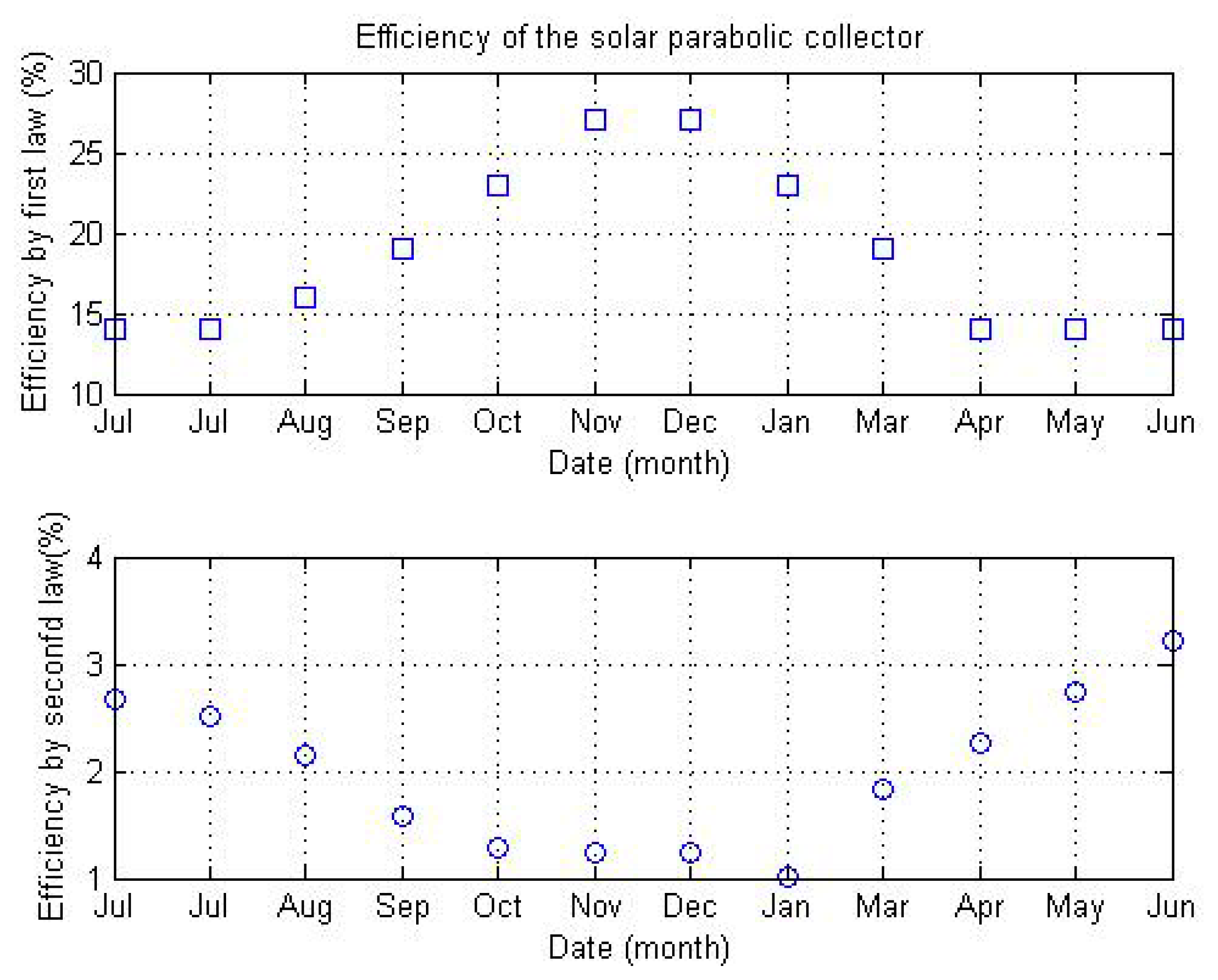
Figure 3 shows the efficiency values obtained using the first and second law of thermodynamics from 2006 to 2007.
It is observed how the low efficiencies are in agreement with those reported by Petela [
8], who estimated that the efficiencies by second law are lower (between 5 and 10 times) than those obtained by the first law. This fact may be ascribed to the heat losses at the surfaces of the reflector and receiver as well as during heat transfer of the useful heat, as it is shown by the exergy analysis. Hence in the present work, the efficiencies of the solar collector, for the first law and second law were of the order of 14% to 27% and from 1% to 3.5%, respectively.
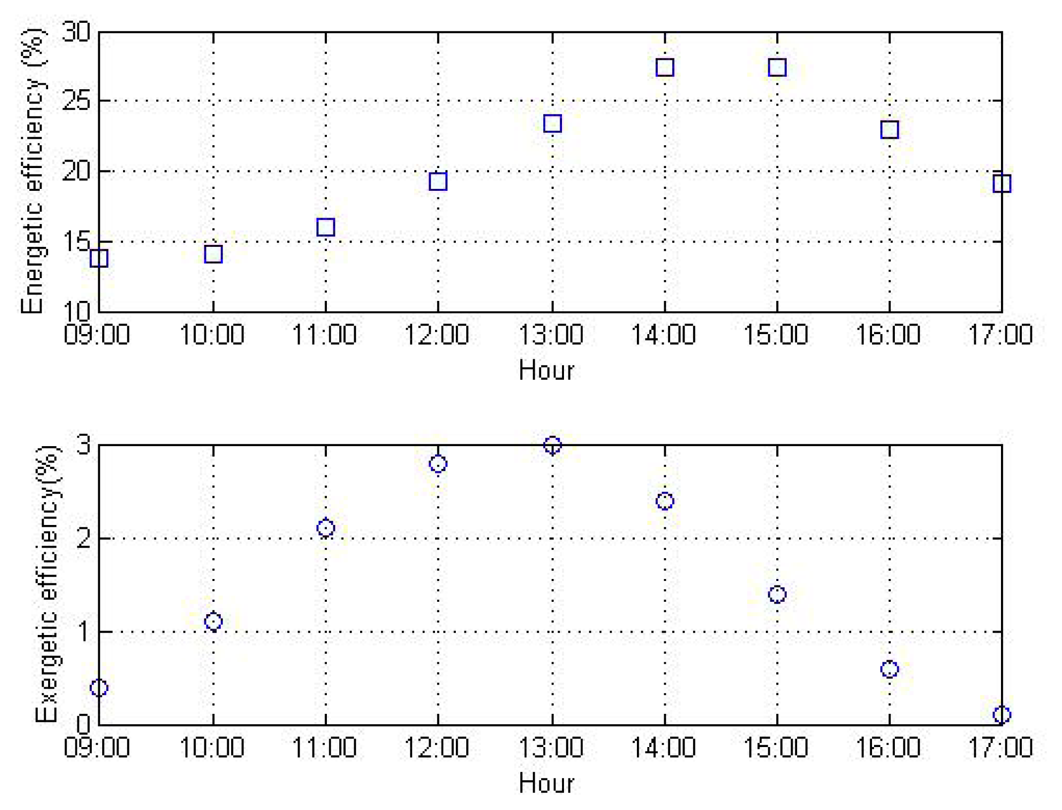
Figure 4 presents the results from a thermal study carried out on 6 January 2011. These data are in agreement with the sinusoidal trend shown on
Figure 3. As a result of this it is inferred that the data obtained from June 2006 to July 2007 can be used to carry out the thermoeconomic analysis of the prototype.
The cost flow rate associated to maintenance and operation of each component of the prototype (Z) was calculated in two different situations,
i.e., using either solar or electrical energy. Both results are shown on
Table 4; each cost is in dollars per hour (USD/h).
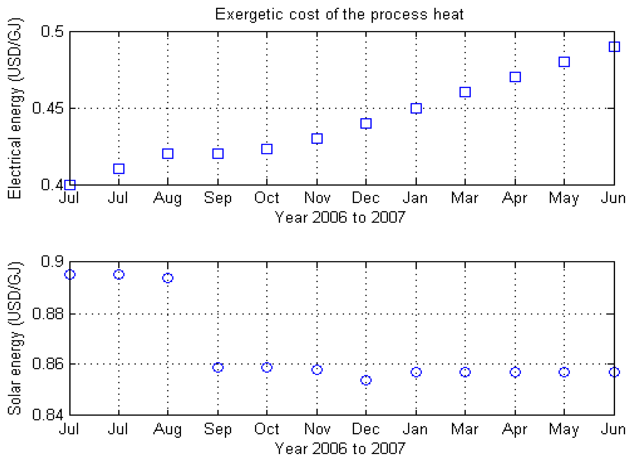
The thermoeconomic method was applied to our solar collector prototype used for heating air. Hence, the unit exergy cost of the process of heating air is about 0.84 to 0.89 USD/GJ, while the cost when electrical energy is used is about 0.40 to 0.50 USD/GJ. Taking into account these results, it is clearly seen that for small units, like our solar collector prototype, the unit exergy cost is higher than that obtained when electrical energy is used. Since on the one hand, the equipment needed to build and run small solar units is more expensive than that needed to operate small units by electricity and on the other, that for the solar collector prototype the exergy destroyed is bigger than that for a small prototype operated by electricity.
It is evident that higher values of cost per unit of fuel as well as a high cost difference are found when the solar process is used to heat air, which is ascribed to a higher cost of the prototype and low efficiencies, On the contrary, when electrical energy is used a better scenario is found due to a low cost of the electrical energy compared to the cost of the solar prototype.
Tables 5 and
6 show the average values, of the thermoeconomic variables, calculated from July 2006 to June 2007.
In addition, some parameters of the solar collector were changed,
i.e., the length of the receiver, air flow rate, the diameter of the receiver and the aperture area in order to obtain optimal values for different scenarios. The results are shown on
Table 7.
It can be observed in
Table 7 that for the case in which the length of receiver was increased, both the exergetics destroyed as well as the cost of the prototype increased, while the thermoeconomic cost of the process is decreased. As a result of this, the exergetic efficiency of the system is enhanced. Hence, the recommended length of the receiver, for this case, is around 3 to 5 m.
It is observed how when the mass flow varies, the exergetic cost, the cost of the prototype Z and energetic efficiency do not vary, whereas when the mass flow is increased the exergetic efficiency is decreased while the thermoeconomic cost of the process does not vary significantly. Then the recommended value of the mass flow is 0.03 kg/s.
In addition, when the diameter of the receiver is changed from 0.01 to 0.07 m, the exergetic efficiency is decreased while the thermoeconomic cost of the process is increased slightly. Then the recommended values of diameter of the receiver are around 10 to 30 mm.
Finally, when the area of aperture of the solar collector varies, prototype costs are slightly increased, while the thermoeconomic cost of the process is decreased. Nevertheless, the exergetic efficiency is enhanced. The recommended value of the aperture area is 3 m2.
Taking into account the thermoeconomic analysis used in the present work, it may be inferred that by using small solar prototypes for heating air, high thermoeconomic values were reached. Nevertheless, if the size of the solar prototype is manufactured with optimum values (length of the receiver, mass flow, diameter of the receiver and area of aperture) low thermoeconomic values could be achieved, which helps to justify the use of solar prototypes.
6. Conclusions
From the parametric studies conducted on the effect of design and operating conditions on the system performance the optimal values of design parameters of a trough collector were established at: length 3 to 5 m, mass flow rate at 0.03 kg/s, diameter of the receiver are around 10 to 30 mm and aperture area is 3 m2. Another interesting point that the analysis of the system reflected was the influence of the cost of the prototype (Z value). The Z value for solar collector systems represents the total cost of the process since technology reduces the cost of solar collector equipment, so projects may be profitable. The cost to manufacture a parabolic trough collector for this application is around 2200 USD. This cost includes the receiver, the concentrator, the fan, vacuum system, pipes and valves. Finally and under the experimental conditions and with the prototype used in the present work, the thermoeconomic analysis showed a higher cost to heat air when a solar prototype is used, compared to that one for conventional energy supplied by the electrical network.


