Securing Relay Networks with Artificial Noise: An Error Performance-Based Approach †


1
Communication Systems Group, Technische Universität Darmstadt, Merckstrasse 25, 64283 Darmstadt, Germany
2
Mathematical and Algorithmic Sciences Lab, Paris Research Center, Huawei Technologies France SASU, 92100 Boulogne-Billancourt, France
*
Author to whom correspondence should be addressed.
†
This work was presented in part in IEEE 8th Sensor Array and Multichannel Signal Processing Workshop (SAM), A Coruña, Spain, 22–25 June 2014, and the 23rd International Conference on Telecommunications (ICT), Thessaloniki, Greek, 16–18 May 2016.
Entropy 2017, 19(8), 384; https://doi.org/10.3390/e19080384
Submission received: 24 June 2017
/
Revised: 17 July 2017
/
Accepted: 18 July 2017
/
Published: 26 July 2017
(This article belongs to the Special Issue Network Information Theory)
Abstract
:We apply the concept of artificial and controlled interference in a two-hop relay network with an untrusted relay, aiming at enhancing the wireless communication secrecy between the source and the destination node. In order to shield the square quadrature amplitude-modulated (QAM) signals transmitted from the source node to the relay, the destination node designs and transmits artificial noise (AN) symbols to jam the relay reception. The objective of our considered AN design is to degrade the error probability performance at the untrusted relay, for different types of channel state information (CSI) at the destination. By considering perfect knowledge of the instantaneous CSI of the source-to-relay and relay-to-destination links, we first present an analytical expression for the symbol error rate (SER) performance at the relay. Based on the assumption of an average power constraint at the destination node, we then derive the optimal phase and power distribution of the AN that maximizes the SER at the relay. Furthermore, we obtain the optimal AN design for the case where only statistical CSI is available at the destination node. For both cases, our study reveals that the Gaussian distribution is generally not optimal to generate AN symbols. The presented AN design takes into account practical parameters for the communication links, such as QAM signaling and maximum likelihood decoding.
1. Introduction
Securing data communications relies heavily on modern cryptography. Since Diffie and Hellman [1] first proposed a key exchange protocol based on computational intractability, computational cryptography approaches have been extensively studied, such as the popular one based on the integer factorization problem [2]. However, the emergence of high-performance computers may challenge the existing cryptographic algorithms relying on computational hardness. As a complementary strategy to provide secure data communications, physical layer secrecy has recently drawn considerable attention. In particular, physical layer secrecy is viewed as a promising solution to provide wireless secrecy in 5G, since it does not depend on computational complexity, and has a high scalability to allow the coexistence of communication terminals with different levels of hierarchical architectures [3]. In addition, physical layer secrecy can either provide direct secure data communication or assist the distribution of cryptographic keys, which makes it particularly favorable in 5G networks [3]. Since preliminary works [4,5] characterized the secrecy capacity for wiretap channels, secrecy communication has been extensively studied for various channel models and network setups, such as single-hop wiretap channels [6,7,8,9,10,11], multi-user networks [12,13], and relay networks [14,15,16,17,18]. In relay networks, secrecy is an important issue even without the presence of external eavesdroppers. Despite the fact that the relay accedes to the request from the source to assist in delivering the message to the destination, it is often desirable to keep the message confidential from the relay [19,20,21,22,23]. First proposed in [19], the untrusted relay scenario has drawn considerable attention, since it finds diverse and important applications in modern communication systems. For example, in heterogeneous networks, the relay terminal may have a lower secrecy clearance than the source and destination pair [21,22]. Therefore, the relay can be partly malicious in the sense that it still functions in compliance with the relaying protocol, whilst it leaks secret information. Another application is the multiple-level access control in wireless sensor networks, where sensors have different authorizations and sensitivities depending on their roles (e.g., master and slave sensors) and type of collected data [24,25,26,27]. In such setups, the relaying node might be only allowed to help forwarding messages from one terminal to another, as not all terminals have direct connections to all nodes in the sensor network. For instance, in a secure sensor network at an airport, terminals with low secrecy levels must have restricted data access, whereas a few terminals at a much higher secrecy level are allowed to access all the data [25].
To shield the messages from the untrusted relay and enhance the secrecy of the wireless communication between the source and destination, one popular scheme at the physical layer is to introduce controlled artificial noise (AN) to efficiently jam the signal reception at the relay. This technique has recently been studied from an information-theoretic perspective, such as secrecy rate and secrecy outage probability, see e.g., [22,28,29,30,31,32]. However, such metrics are in general valid for ideal communication assumptions of continuous input messages and random encoding schemes with asymptotically large block lengths. In order to take discrete modulation alphabets and finite block lengths into consideration, other secrecy performance metrics have also been proposed, such as bit error rate [33,34]. The observation that in modern wireless communication systems square quadrature amplitude modulation (QAM) is widely used motivates us to address the problem of how to optimally apply AN to enhance the physical layer secrecy in an untrusted relay network. The symbol error rate (SER) of the demodulated signal at the relay is used as a performance metric in this paper.
In this work, we consider the communication between a pair of source and destination terminals, where a direct link is absent, and therefore, a half-duplex relay terminal is utilized to assist the communication [35,36]. To forward the signal from the source to the destination, the relay employs the non-coherent amplify-and-forward (AF) protocol [37], which is considered as the most promising solution for current and future communication systems, since it offers a reasonable tradeoff between the benefits and implementation costs [38]. As a result, these relays have already been incorporated in the Universal Mobile Telecommunications System (UMTS) and Release 8 of Long-Term Evolution (LTE) in the form of repeaters [35]. For the AF protocol, we make the common assumption that the destination has the instantaneous channel state information (CSI) of the relay-to-destination link and the aggregate source-to-relay-to-destination link [39,40]. Consequently, the destination can obtain the CSI of the relay-to-destination link, which is however not available at the relay. To secure messages against the relay, we propose a novel AN scheme, where the destination designs and broadcasts AN symbols to the relay simultaneously with the transmission of the symbols from the source. It has been shown that a positive secrecy rate can be achievable in this AN-assisted untrusted relay network [41]. For this setup and with the knowledge of instantaneous CSI as assumed in Section 3, we first investigate the problem of how to optimally design the AN to maximize the SER of QAM signals at the relay. Note that the requirement of the instantaneous CSI might be strong in some practical systems. To reduce the requirement, we then investigate the AN design based on statistical CSI in Section 4, i.e., the channel variances. For fading channels, an important performance metric is the average SER (ASER), which quantifies the average decoding error performance over fading channels. Interestingly, for both CSI schemes, our study shows that it is not optimal to generate AN from a Gaussian distribution. For example, based on instantaneous CSI, we note that a QAM or a rotated QAM AN generating method maximizes the SER at the relay. The results in this paper can be used as benchmarks for future analyses of AN-based techniques. The main contributions of this work can be summarized as follows:
- By assuming that instantaneous CSI is available at the untrusted relay and the destination, upon receiving both of the QAM symbols from the source and the AN from the destination, an exact expression for the SER at the relay when decoding the QAM symbols is first derived. Under an average power constraint, this expression is then utilized to obtain the phase and power distribution of the AN symbols to maximize the SER performance at the relay.
- For the case where only statistical CSI is available, we first derive an exact expression for the ASER performance at the relay. Next, the optimal power distribution of the AN symbols that maximizes the ASER performance at the relay is determined. Numerical and simulation results demonstrate that the proposed optimal AN designs guarantee significant error rate performance enhancement compared with conventional AN designs, such as Gaussian distribution.
Furthermore, the AN-based scheme studied in this paper is formulated according to the framework of current cellular standards such as LTE/LTE-Advanced of 4G and the next major phase of mobile telecommunications standard 5G [3,36]. By applying an additional processing unit to generate AN, the studied scheme can be easily embedded in a practical system to secure wireless communications, e.g., key transmission or control signaling. Moreover, our study provides exact SER expressions of the QAM signals at the relay, which can be used as benchmarks for future extensions, e.g., deriving SER expressions for other modulation schemes, and designing AN signaling in other scenarios.
Notation: Throughout this paper, we use to represent a complex circularly symmetric Gaussian distribution with mean and variance . We use and to denote statistical expectation and probability. Moreover, and represent absolute value and complex conjugate of b, respectively.
2. System Model and Problem Formulation
Let us consider a relay communication channel as shown in Figure 1. A legitimate transmitter (the source) sends information symbols to a legitimate receiver (the destination) assisted by an untrusted relay. We assume that a direct link between the legitimate terminals is not available due to, for example, high path loss. All the terminals are configured with a single antenna (Note that this work can be generalized to the scenario where at least one of the source and destination has multiple antennas. Whilst beyond the scope of this work, the corresponding precoding design at each terminal remains an interesting topic for future extension). We assume quasi-static Rayleigh fading channels and the channel coefficients for the source-to-relay and relay-to-destination links are respectively denoted by h and g, where and . All channels are assumed to be reciprocal [42] and constant within the transmission duration from the source to the destination. The transmission from the source to destination can be partitioned into two time slots. During the first time slot, the source broadcasts the symbol m. Meanwhile, to prevent the relay from deciphering the information, the destination sends the AN symbol z to increase the noise level at the relay. For this purpose, all the terminals are assumed to be perfectly synchronized. Similar to physical-layer network coding [43], the synchronization is an important issue, which requires further investigation. At the end of the first time slot, the received baseband signal at the relay can be mathematically expressed as,
where the additive white Gaussian noise (AWGN) symbol n is assumed to be zero mean and have the one-sided power spectral density in Watts/Hz. During the second time slot, the source is muted, and the relay applies the amplify-and-forward protocol [37] to forward a scaled version of its received signal to the destination. Upon receiving this signal, the destination removes the AN z prior to decoding m. For the afore-mentioned communication protocol, the destination is required to have the perfect CSI of h and g in order to maximize the system’s transmission rate [44]. To be more specific, the destination performs the channel estimation of the relay-to-destination link and the compound source-to-relay-to-destination link, and the channel coefficient of the source-to-relay link is then obtained [40].
While exploiting the untrusted relay to help the data transmission, the system is designed to ensure that the untrusted relay cannot decipher the source’s symbol m. In addition, we assume that the relay can obtain knowledge about the modulation scheme of the source, e.g., by tracking the common control channel of the network. Moreover, it is important to note that the AN z in Equation (1) is designed and known solely by the destination so that the relay is not able to distinguish between the AN and the regular channel noise n. Therefore, when decoding the symbols transmitted by the source, we assume that the relay treats the AN from the destination as noise. Furthermore, we assume that the source transmits demodulation reference signals (DM-RS) [36] so that the relay can perfectly estimate h to perform ideal coherent demodulation as,
Forwarded by the relay, the destination also has access to h and the DM-RS of the source in order to demodulate the signal m. For the source’s symbol m, we consider square M-QAM modulation types with and , which are frequently used in the current and upcoming communication standards [36]. We also make the common assumption that constellation points are uniformly distributed [45]. In addition, we use and to denote the average energy per symbol for the source’s signal m and the AN z sent by the destination, respectively. Finally, is assumed to be known at the destination for the AN design.
Since the destination has perfect knowledge of the instantaneous channel coefficients h and g, this knowledge can be efficiently used to design the AN symbol z. The relay uses the ideal coherent demodulation with minimum distance detection to recover the source’s signal m, and the corresponding SER is the performance metric used in this paper. The objective is to find out the AN symbol z at the destination in order to maximize the SER performance of the square M-QAM modulation at the relay, which we address in Section 3.
3. AN Maximizing Relay’s SER Performance
The SER analysis in this section consists of three parts. In Section 3.1, for given instantaneous channel realizations h and g, we derive the SER expression at the relay for the given AN symbol z of square M-QAM modulation. Based on this expression, in Section 3.2, we further study the problem of how to select the phase of z given its amplitude . The problem of assigning power to the AN symbol z is considered in Section 3.3, where we derive the optimal distribution of the power of z, i.e., , based on the average power constraint .
3.1. SER Expression for a Given z
The SER performance of the square M-QAM modulated signaling over AWGN [45] and over fading channels [46] has been widely studied. To provide a comprehensive study on the SER performance at the relay, we first investigate the AN design using the instantaneous CSI in this section, and our SER analysis is based on the procedure presented in ([45], Chapter 5).
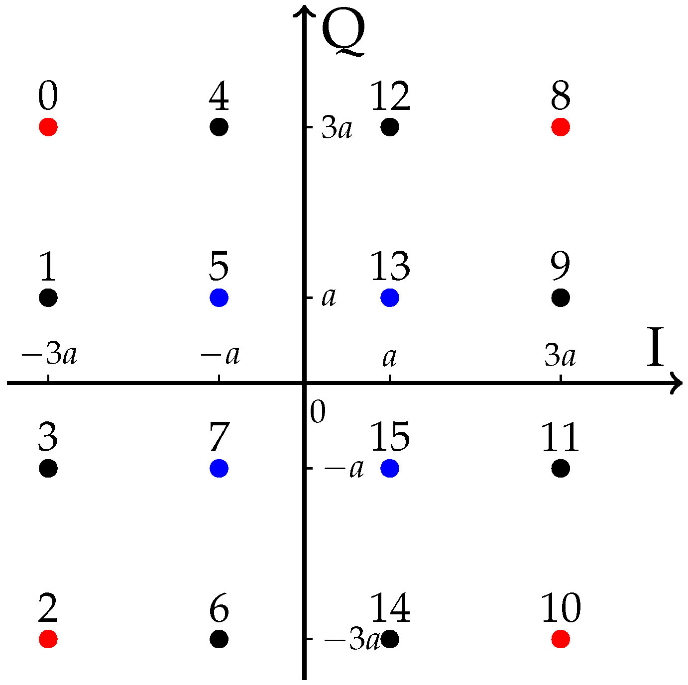
As an example, the constellation diagram for the square 16-QAM modulation is illustrated in Figure 2. Denote the minimum distance between two constellation points as (), then for a general M-QAM constellation, the average energy per signal symbol can be expressed as ([45], Equation (5-2-76))
where denotes the symbol duration.
Since the AN design in this section is based on h and g, for simplicity of notation, we define and in Equation (2), and denote the real and imaginary parts of s and as , and , , respectively. Thus, we have that and with . Note that the equivalent noise is identically distributed with n, and thus , where . For a vertex such as the point “0” in Figure 2, the received symbol in Equation (2) lies outside the decision region of the point “0” if or . Thus, given s, the error probability of the point “0” is given by , which can be computed as,
where is the Gaussian Q-function ([46], Equation (4.1)). Similarly, the error probability for the ith constellation point () is obtained by computing the probability that in Equation (2) lies outside its decision region. Based on the assumption that the constellation points are uniformly distributed, for a given z, or equivalently for a given s, the SER of the square M-QAM signal at the relay can be derived by averaging the respective error probability expressions for all symbols under the assumption of a uniform symbol distribution, resulting in,
where . Using Equation (3), we have that,
Note that in the case of , the SER expression in Equation (5) coincides with that of the AWGN channel ([45], Equation (5-2-79)).
Before proceeding, it is interesting to note that the SER expression in Equation (5) depends on the real and imaginary parts of s, which motivates us to express s as,
where we have expressed z, g and h as , , , respectively, and . Now, inserting Equation (7) into Equation (5), the SER expression can be rewritten as a function of and as,
From Equation (8), we can observe that the channel gains and play an important role in the SER performance, which we summarize in the following propositions.
Proposition 1 (SER decreases in ).
The SER in Equation (8) is a monotonically decreasing function of .
Proposition 2 (SER increases in ).
The SER in Equation (8) is a monotonically increasing function of .
To prove these propositions, we denote,
and,
We first focus on Proposition 1. Since is a decreasing function of , the first derivative of with respect to satisfies , and for a given , . Similarly, and for a given , . In addition, since , the first derivative of the SER expression of Equation (8) with respect to can be written as,
which proves Proposition 1. This proposition agrees with the intuition that a stronger source-to-relay link improves the decoding performance at the relay.
Regarding Proposition 2, for a given , we use the first derivative of the Gaussian Q-function
to obtain,
which indicates that is an increasing function of . Thus, we have,
Therefore, since , the first derivative of the SER expression of Equation (8) with respect to can be derived as,
which proves Proposition 2. This proposition suggests that a stronger relay-to-destination link deteriorates the SER performance at the relay.
A careful observation of Equation (8) shows that the AN design can be decoupled into the optimal design of the phase and the amplitude, respectively. In the following subsection, we first derive the optimal rotation angle that maximizes the SER given by Equation (8). The value of , which denotes the corresponding phase of the AN defined following Equation (7), is then determined accordingly.
3.2. Selecting for a Fixed
The focus of this subsection is to determine the optimal phase distribution of the AN symbol z. In this case, the power of the AN is assumed to be fixed. Then, for simplicity, we can omit in the argument of in Equation (8) and denote the SER expression as in the remainder of this subsection.
Due to the -periodicity of the function and due to its symmetry, we only consider the interval to determine the maximum of . We first numerically verify the following result.
Result 1: is a quasi-convex function of for all , and either or maximizes the value of .
To illustrate this result, consider the constellation point “5” in Figure 2 as an example. Given the power of the AN symbol z, in order to maximize the expected SER with square 16–QAM modulation at the relay according to Result 1, the destination can either allocate all the power to the direction of “12” or “13”, or equally distribute this power between the directions of “12” and “13”. Due to the similarity of this AN phase design to the constellation diagram, we refer to the case of as the rotated QAM phase selection and the latter case of as the QAM phase selection. Accordingly, the optimal phase selection of the AN z is computed as or .
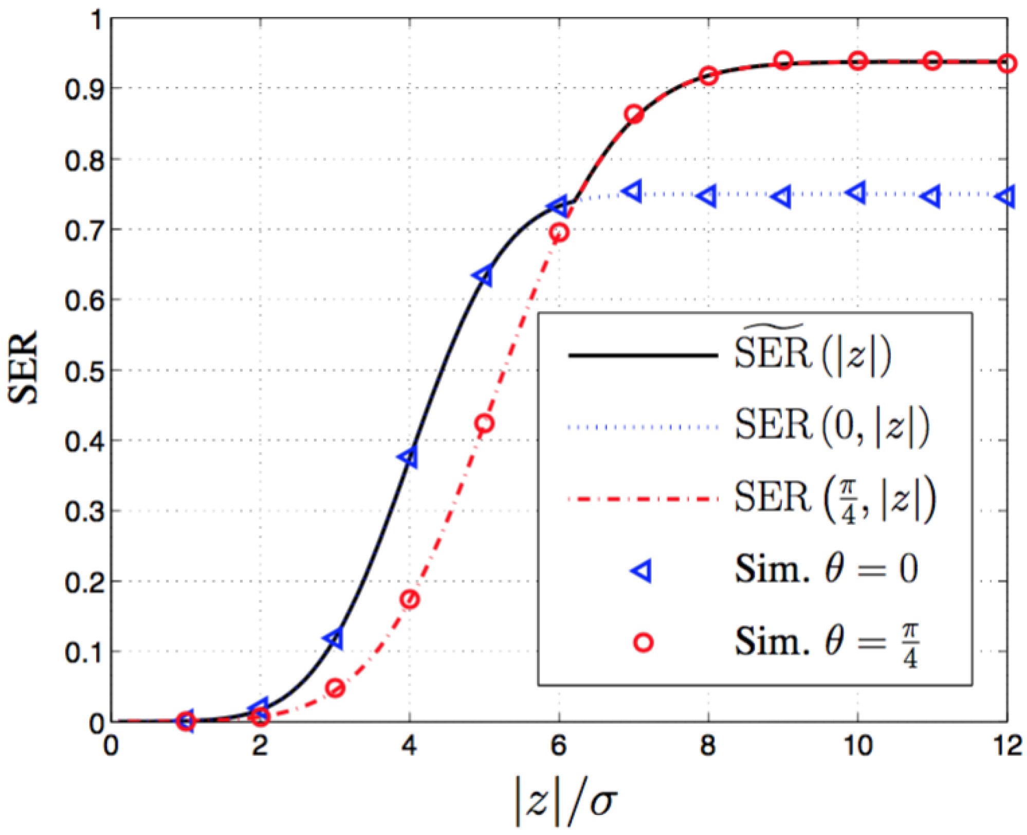
Next we address the question as to in which case using the rotated QAM constellation for the AN maximizes the SER at the relay and in which case the M-QAM constellation is optimal. Towards this aim, we obtain Figure 3, which shows as a function of . Note that and correspond to the levels of AN-to-natural noise ratio (ANR) and signal-to-noise ratio (SNR), respectively. Each curve in this figure is plotted by numerically solving the equation for for given values of . The QAM region and the rotated QAM region denote the regions of and , respectively. Therefore, Figure 3 displays phase selection thresholds for different system parameters. In this figure, and indicate the energy of the source signal m and the energy of the AN z, respectively. We focus on the relation between the signal energy and the AN energy, and thus ignore the effect of channel gains by assuming and .
The curves in Figure 3 show that for a given signal power, there exists a threshold for the AN power, under which the optimal phase selection is , and above which the optimal phase selection is . To explain the intuition behind this, consider the constellation point “5" in Figure 2. With the purpose of maximizing the SER performance at the relay, if the power level of the AN is low (as compared to a given signal power ), the AN transmitted from the destination may deviate the equalized information signals received at the relay towards the adjacent constellation points “1”, “4”, “13”, and “7”, whilst if the power level of the AN is sufficiently high, the AN may shift the receive symbol towards the farther constellation points “0”, “12”, “3”, and “15”. From Figure 3, one can also observe that for small values of , the values of the threshold are very close to zero. This fact indicates that QAM phase selection is the preferable scheme if the received SNR at the relay is low.
In particular, from Equation (8), we have,
and,
where the equality in Equation (16) holds only when , i.e., when no signal is transmitted. This indicates that when the signal is present, given sufficiently high AN noise power, the QAM phase selection yields a higher SER. This analysis is illustrated by the plot in Figure 3. Also note that is the SER when the relay does not have any prior information and randomly guesses the value of signal m for decoding, which serves as an upper bound on the SER of any AN scheme. In this work, we term this as non-informative error performance. Moreover, Equations (16) and (17) reveal that when the AN power is sufficiently high, the M-QAM selection asymptotically achieves the non-informative error performance.
3.3. Assigning for a Given
In Section 3.2, we have shown how to select the phase of z if the amplitude is a fixed value. In general, however, it may be optimal to assign different powers to different AN symbols for a given average AN power. In this subsection, we assume that the average energy per AN symbol is limited to an average symbol energy , i.e.,
Furthermore, we denote as the average power of z. Based on the results in Section 3.2, the expected SER obtained from optimal phase selection is given by,
where the is defined according to Equation (8). Following the proof of Proposition 2, one can show that the first derivative of in Equation (8) with respect to is non-negative, and thus is a monotonically increasing function of for a given . Accordingly, in Equation (19) is also a monotonically increasing function of . Figure 4 displays the values of for 16-QAM and , where both the analytical and the simulated results are plotted. From the figure, we can see that as increases, the rotated QAM and the QAM phase selections alternatively achieve a better SER performance. In this figure, note that can be viewed as a deterministic power usage.
The objective of this subsection is to derive the optimal distribution of to maximize the expected value of the SER in Equation (19), given the instantaneous CSI h and g. Alternatively, the power needs to be smartly allocated to yield an upper bound on the SER performance with deterministic power usage. Denoting the probability density function (PDF) of as , by taking into account the power constraint in Equation (18), the following optimization problem can be formulated:
where the average power constraint Equation (20b) follows from Equation (18). For computational tractability, we only consider PDFs for which all integrals in Equation (20) exist.
The following theorem provides interesting insights into the power allocation problem and meanwhile can greatly simplify the computation of the PDF of .
Theorem 1.
(SER-maximizing power distribution): Any PDF solving the problem in Equation (20) has the form,
where is the Dirac delta function defined by ([47], Chapter 2),
for any continuous function g and any value of , and,
with .
Proof.
See Appendix.
☐
This theorem means that only two types of AN symbols are generated from the destination, one with probability and one with probability p, and the corresponding powers are and , respectively. It is important to note that following Appendix, Theorem 1 is valid for any as long as is a monotonic increasing function. Inserting Equation (21) into Equation (20), the expected SER in Equation (20a) can be computed as,
From Equation (24), at high average AN power, i.e., , we observe that the expected SER in Equation (24) approaches , which corresponds to the non-informative error performance. The proof can be sketched as follows. From Equations (16) and (17), we know that . Given , by applying the Optimal Power Allocation Theorem, we have due to . In this case, if , we have and , thereby in Equation (24) approaches . If is a finite value, , then the term in Equation (21) approaches zero, and the term in Equation (21) converges to , which explains the above observation.
Another interesting observation is that the maximum is a monotonically decreasing function in . This is because in Equation (24) is a linear combination of and , each of which is a monotonically decreasing function of as previously shown. Furthermore, maximizing with respect to and preserves the monotonicity. Similarly, it can be shown that in Equation (24) is a monotonically increasing function of . Therefore, by applying the optimal AN design, the SER at the relay increases with the relay-to-destination link quality and decreases with the source-to-relay link quality.
The optimal values of and maximizing in Equation (24), denoted by and , can be computed numerically based on h, g, , M, a, and . Substituting and back into Equation (24) yields the maximum expected SER, which is denoted as . For example, in the case of , , , , , and , the optimal values can be computed as and , yielding and . The corresponding maximum expected SER is . Interestingly, if we use a deterministic power usage , i.e., the AN PDF written as , the corresponding expected SER is 0.0371. Therefore, applying Theorem 1 at the destination yields a SER increment of at the relay compared with the deterministic power usage.
Here, we summarize the procedure to design and generate AN symbols as follows:
- (1)
- compute the amplitudes of the AN symbols by numerically maximizing Equation (24),
- (2)
- determine the corresponding phase value for each amplitude using Equation (19),
- (3)
- generate the AN symbols by the obtained amplitudes and phases.
From the procedure, we can see that the computational complexity of the AN generation mainly stems from the optimal amplitude computation in step (1). There exist numerous non-linear optimization algorithms to solve this optimization problem, such as the Newton–Raphson method, and the Nelder–Mead method [48], which is known as “fminsearch” implemented in MATLAB. For example, using “fminsearch” with the default termination tolerance, i.e., , the iteration number to solve the problem is generally under 100 for the numerical examples in Section 5. Moreover, note that the computation in steps (1) and (2) is required after the change of the channel coefficients h or g.
3.4. Relation between Phase Selection and Power Allocation
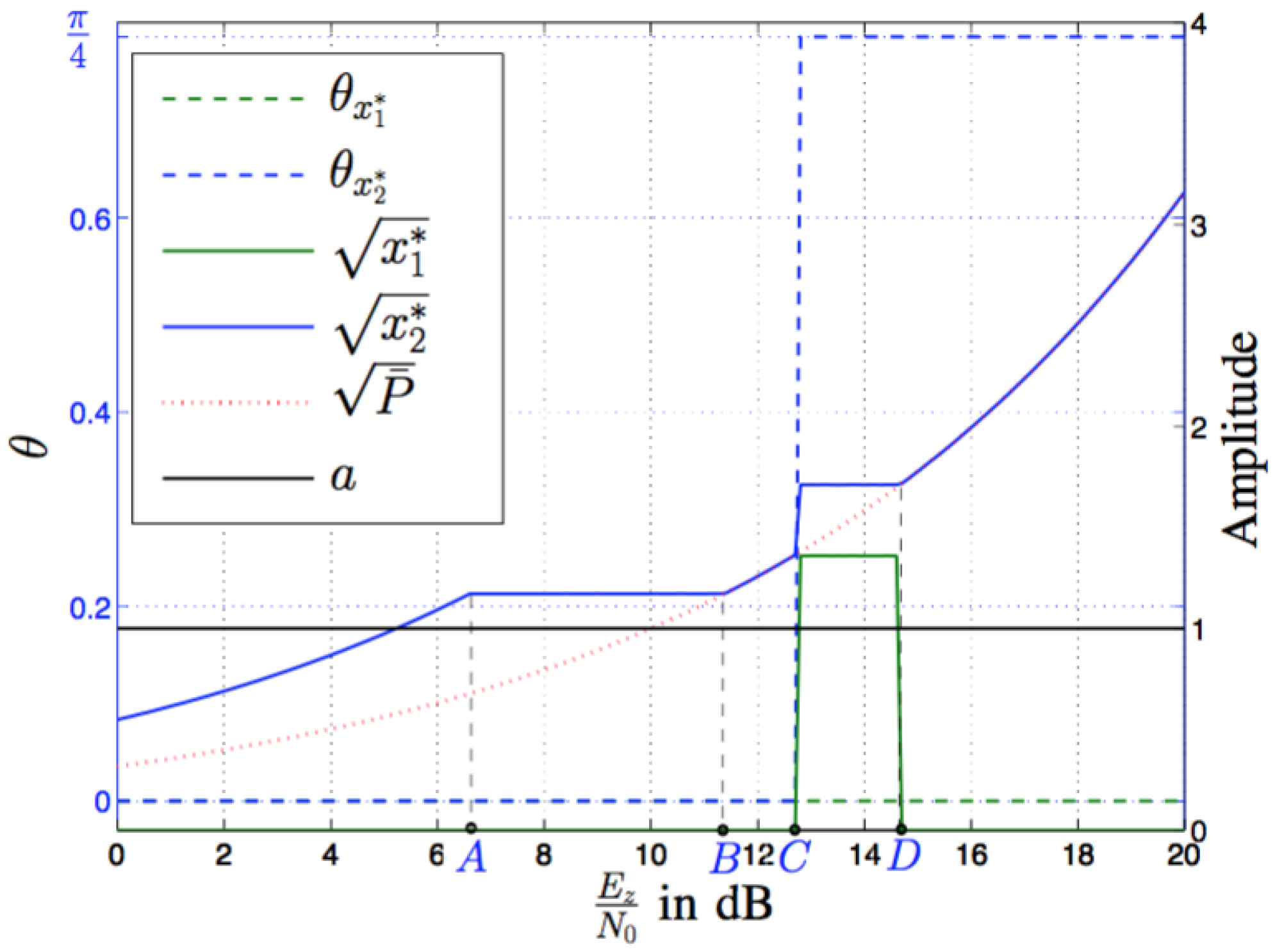
Having determined the optimal phase selection and the SER-maximizing power distribution, it is interesting to examine their interplay in the SER performance, which we illustrate in Figure 5, Figure 6 and Figure 7. Figure 5 depicts the SER performance using a deterministic power level and the optimal power allocation. The line denoted as “non-informative” represents the non-informative SER performance. In the case of 16-QAM, the non-informative SER is equal to . Comparing Figure 4 and Figure 5, we observe that for a given SNR , the derived Theorem 1 yields an upper bound on the SER with the deterministic power usage, i.e., the curves and . To take a deeper look, we depict in Figure 6 the relation between the optimal power allocation and . The corresponding phase selection and are obtained from evaluating and in Equation (19), respectively. Figure 7 plots the probability to transmit , i.e., p given in Equation (23), noting that the probability to transmit is given by .
In correspondence to Equation (21), we observe from Figure 6 and Figure 7 that as the power of the AN increases, either the probability p remains constant and the powers or, increase or the values of and remain constant (with ) and the probability p of transmission with the larger power increases. To simplify the discussion of Figure 5, Figure 6 and Figure 7, we partition the values of the AN-to-natural noise ratio (ANR) per symbol into multiple regions by introducing the transition points A–D. From these figures, we obtain the following observations. Region I (): In this region we observe that when the ANR is low, the optimal AN design is to transmit a noise symbol with power and rotated QAM phase at a constant probability , and to transmit no AN () with probability . Thus, as increases, the power increases while the probability of transmitting AN remains constant.
4. AN Maximizing Relay’s ASER Performance
Region II (): When the ANR is medium, the power to transmit rotated QAM AN symbols reaches a constant, and the probability to transmit the AN symbols increases as increases. The corresponding SER in Figure 5 is higher than those using the deterministic power .
Region III (): In this region, the probability to transmit AN symbols with the rotated QAM phase selection reaches 1, and the corresponding transmitting power reaches the highest . In other words, for the AN symbols, the deterministic power usage and the rotated QAM phase selection achieve the maximum SER, which can also be observed in Figure 5.
Region IV (): The ANR arrives at a threshold , above which the optimal AN design is to use both of the two kinds of AN symbols: the rotated QAM phase selection with power and the QAM phase selection with power . The probability to transmit the QAM phase selection symbols increases as the ANR increases.
Region V (): When the ANR is large, the QAM phase selection with a deterministic power achieves the maximum SER. In particular, when is sufficiently large, i.e., dB in Figure 5, the SER converges to the non-informative SER, which was mathematically proved in Equation (17).
To intuitively understand the above observations, again take the constellation point “5” in Figure 2 as an example. When the AN power is low, the optimal AN generation scheme is to burst the limited power to move “5” towards the adjacent points “1”, “4”, “13” and “7” in order to introduce decoding errors. As the AN power becomes sufficiently large, some of the power can be used to move “5” towards the points “0”, “12”, “3” and “15” in order to induce more decoding errors. Until the AN power becomes significantly large, beaming all the power to the directions of points “0”, “12”, “3” and “15” yields the maximum SER.
In Section 3, we have obtained the optimal phase and amplitude distribution of the AN based on the instantaneous channel knowledge of the source-to-relay and relay-to-destination links. In this section, we consider the optimal distribution of the AN symbol power that maximizes the ASER performance of the M-QAM modulation at the relay provided that the long-term statistical CSI is known to the destination. Following a similar approach to Section 3, we first present an analytical expression for the aforementioned performance metric over Rayleigh fading channels. The optimal phase and power distributions of the AN that maximizes this performance are then determined.
4.1. ASER Expression for a Given z
In this section, the channel coefficients h and g are assumed to be random variables. Moreover, the envelope of the relay-to-destination channel coefficient g is assumed to be Rayleigh-distributed. For a given AN symbol z, the received AN at the relay can be easily shown to be distributed as . This indicates that the received AN at the relay is an extra source of the AWGN n. Hence, as can be observed from the signal model in Equation (1), the overall received noise at the relay is a superposition of the AN and the natural AWGN. The relay-to-destination channel coefficient g and the AWGN symbol n are independent, and it can be easily shown that the received noise is distributed as , where is the variance of the AWGN n. For Rayleigh faded source-to-relay channel gain and the overall noise symbol , the performance of the M-QAM modulation at the relay can be obtained using ([46], Equation (8.106)) as,
where represents the average received SNR per symbol.
Similar to Propositions 1 and 2 made on Equation (8), the effects of channel statistics on the ASER given by Equation (25) can be summarized as follows.
Proposition 3 (ASER monotonicity).
The ASER in Equation (25) is a monotonically increasing function of , as well as a monotonically decreasing function of .
This proposition is intuitive and is similar to Propositions 1 and 2 in Section 3: Stronger relay-to-destination channels help to deteriorate the ASER performance at the relay, whereas stronger source-to-relay channels improve the average decoding performance at the relay.
Proposition 4 (high signal and AN power performance).
At high SNR and high ANR, i.e., and , .
Proposition 4 reveals that provided an adequately high signal and AN power is available, the relative strength of the source-to-relay and relay-to-destination links affects the ASER performance of the QAM signals at the relay.
Proposition 5 (high AN power performance).
In the high AN power regime, i.e., for , , we have .
This proposition shows that given sufficiently high AN power, the ASER at the relay is close to the non-informative error performance.
Furthermore, we observe that the ASER expression in Equation (25) is independent of the phase of the AN, which is different from the AN design in Section 3 in the case of instantaneous CSI. Following a similar approach as in Section 3.3, our objective in the following subsection is to derive the SER-maximizing power distribution for the AN under an average power constraint.
4.2. Assigning for a Given
We rewrite the function in Equation (25) as to reflect the effect of AN power, where . Similar to Subsection 3.3, the optimal power assignment problem is given by replacing in Equation (20) by , and now represents the PDF of x for Rayleigh fading channels. Since one can see that in Equation (25) is a monotonically increasing function of x, the distribution of the optimal AN directly follows from the PDF expression derived in Equation (21). Therefore, substituting Equation (21) into Equation (25) yields the expected ASER,
where is the average power constraint on the AN, and . The optimal values of and maximizing in Equation (26) are then derived numerically based on , M, , , , and , where and represent the statistical/long-term CSI. Note that the computational complexity of the derivation has been investigated in Section 3.3.
Similar to the analysis following Equation (24), we can also show that as the AN power increases, the expected ASER in Equation (26) converges to the non-informative SER performance.
5. Numerical and Simulation Results
In this section, we present simulation results to validate the obtained analytical results derived in the previous sections. In all figures, the average SNR to the transmitted information symbol is chosen as dB.
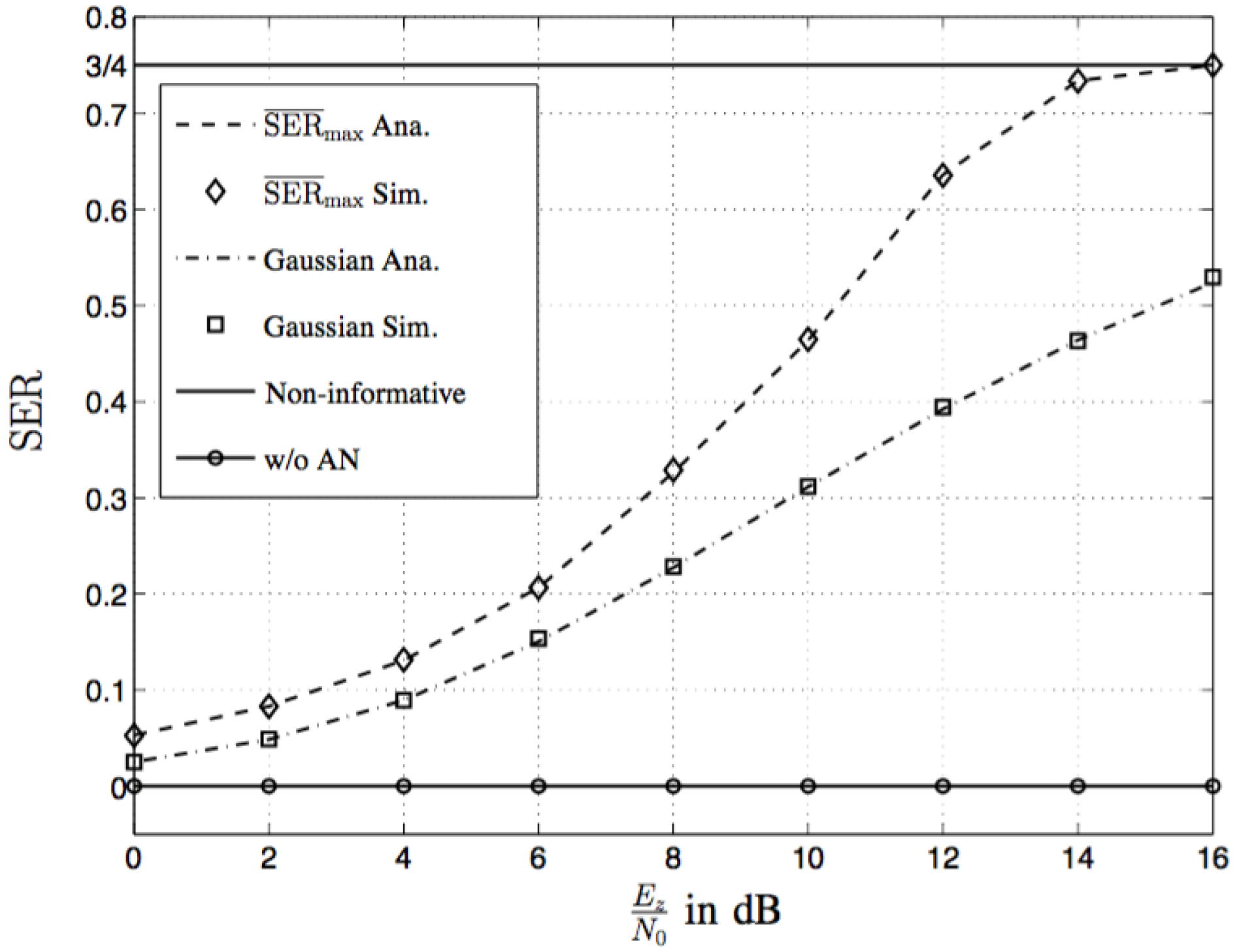
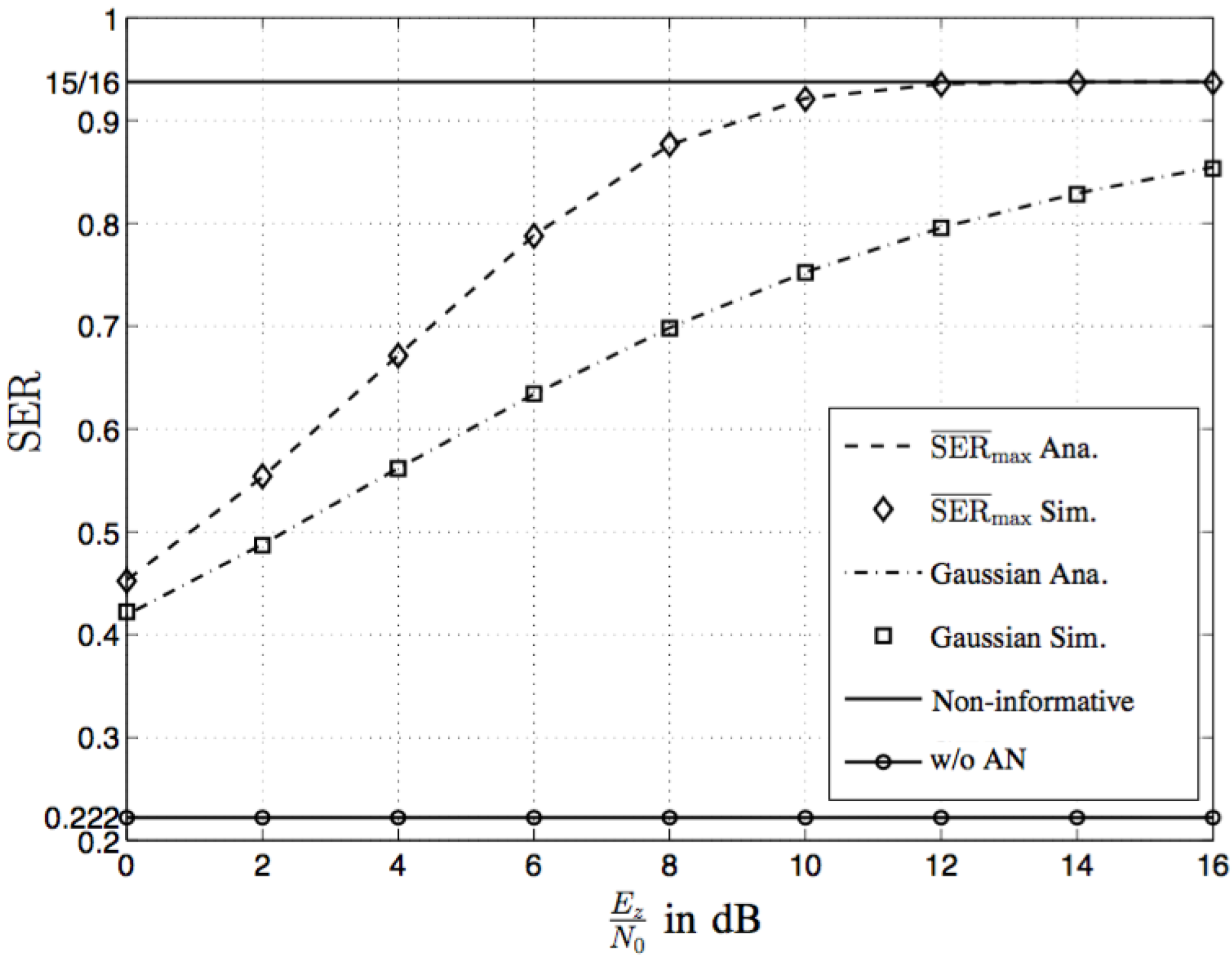
In order to depict the SER performance at the relay using the optimal AN design in Section 3, we plot Figure 8, where the signal symbol m is randomly selected from the square 4-QAM constellation, and the channel gains g and h are simply assigned as 1. We observe that all analytical results coincide very well with the corresponding simulation results. For the sake of comparison, the expected SER values for Gaussian AN are also plotted in Figure 8. In the Gaussian case, we assume that the AN symbol z is generated according to a complex Gaussian distribution with the same average symbol energy . The line denoted as “non-informative” represents the non-informative SER performance, which has been defined after Equation (17). The curve “w/o AN” in the figure depicts the SERs at the relay without AN, which lie at a value of 0.0016 for the given parameters. Figure 8 shows that the SER at the relay can be significantly increased by applying our AN design. Even when the ANR is small, e.g., dB, the SER is increased from 0.0016 to 0.05, i.e., an increment of . Moreover, Figure 8 clearly demonstrates that the Gaussian distribution is not optimal for the AN symbol generation, since our scheme described in Section 3 can induce much larger SER at the relay. For the case shown in Figure 8, if the ANR is above 16 dB, the maximum SER, i.e., , achieves . This fact indicates that if the AN z is properly generated and is above a certain threshold, applying ideal coherent demodulation at the relay does not lead to better performance than the non-informative case, and secure data transmission can therefore be ensured by the proposed AN design. Figure 9 shows the SER performance for square 16-QAM constellations. Comparing Figure 9 with Figure 8, similar observations can be made as for the case of 4-QAM.
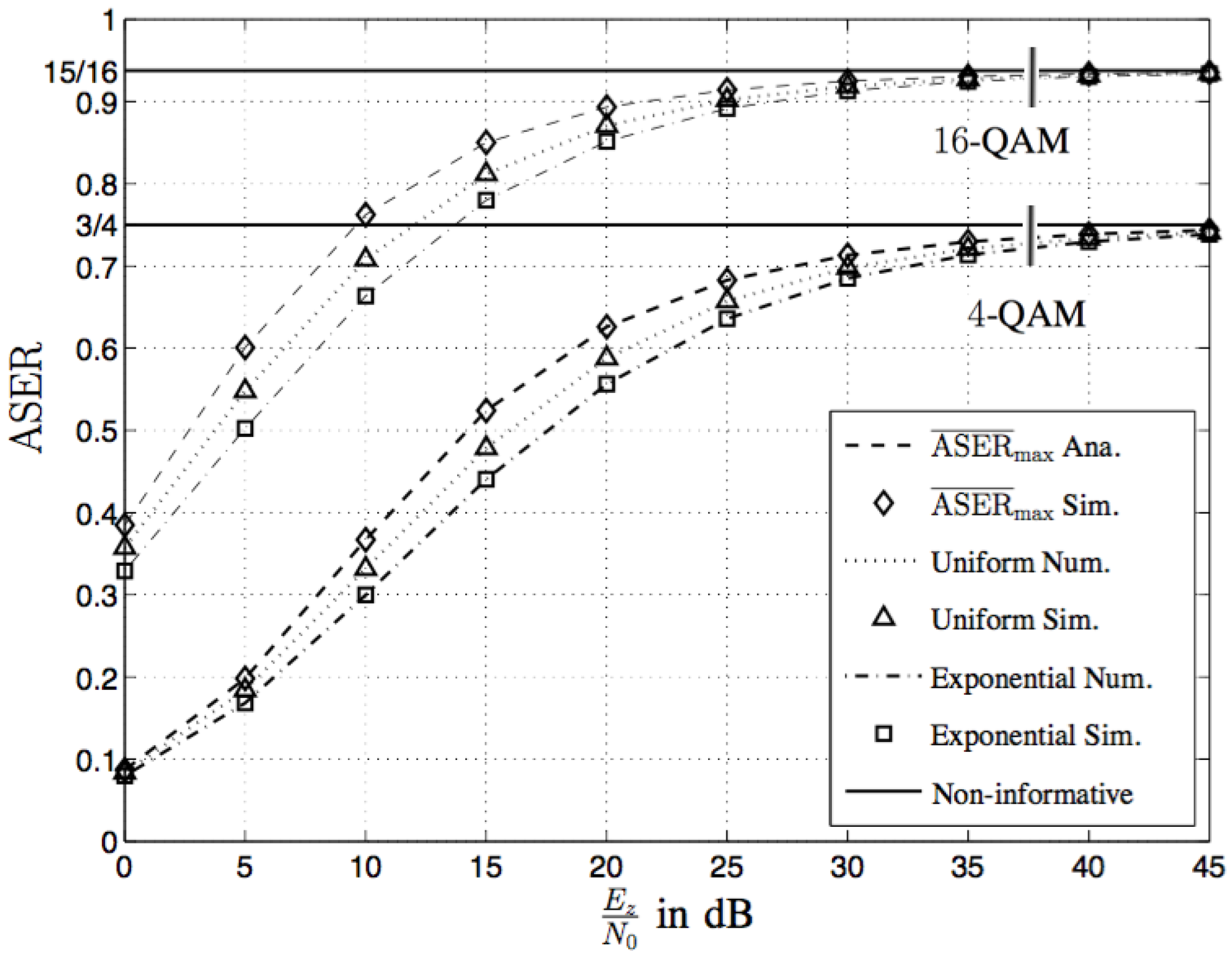
Now, we investigate the ASER performance at the relay using the optimal AN design in Section 4. Figure 10 depicts the ASER performance for square 4-QAM and 16-QAM signals. In this figure, for each QAM constellation, the curve “ Ana”. is computed by numerically maximizing in Equation (26) with respect to and . The maximization revealed that the optimal power allocation is with probability for both of 4-QAM and 16-QAM signals. In other words, different from the AN design based on the instantaneous CSI in Section 3, constant power usage is optimal to design the AN based on the statistical CSI. Intuitively, due to the averaging effect over several channel realizations, the ASER performance is not sensitive to the different instantaneous power allocations. For comparison, the ASER curves ( Ana./ Sim.) for various power distributions are plotted, i.e., the uniform and the exponential power distribution. For each curve, the numerical results are obtained from computing , where,
and,
are the PDFs of the AN power with uniform and exponential distributions, respectively. Note that there exist numerous AN designs with exponentially distributed power, such as the Gaussian distributed AN. Figure 10 shows that our proposed scheme with the SER-maximizing power distribution yields the largest ASER at the relay. Given sufficiently high ANR, all the ASER curves achieve the non-informative error performance, which confirms Proposition 5. However, the performance difference between different AN designs is not significant. This can be explained by the fact that the ASER expression in Equation (25) does not consider the phase of the AN, and the degree of freedom of the phase design for the AN is not utilized.
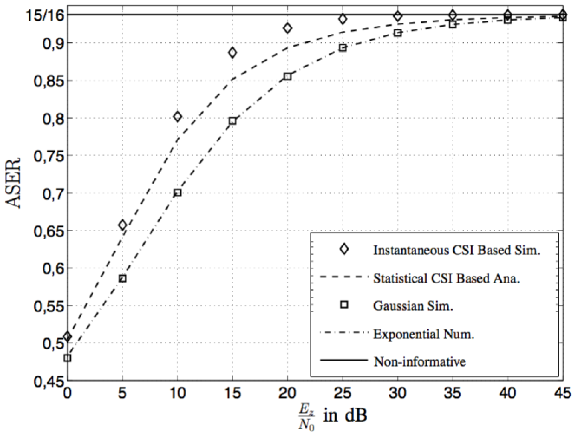
Furthermore, it is interesting to compare the SER performance of the optimal AN designs in Section 3 and Section 4. Figure 11 compares the ASER performance of various AN designs. In the figure, the “Instantaneous CSI-Based Sim.” curve is plotted by computing using the Monte Carlo method, and the curve “Statistical CSI-Based Ana.” is plotted using the same method as in Figure 10. The curve “Gaussian Sim.” is plotted by numerically computing , with Gaussian-distributed AN. From Figure 11, we observe that the instantaneous CSI-based AN design yields a higher ASER than the statistical CSI-based AN design, which is consistent with our intuition. However, the performance difference between these two designs is not quite significant. Without optimal phase and power designs, the Gaussian distribution performs worse than both CSI-based AN designs.
6. Conclusions
In this paper, we have investigated physical layer secrecy for a two-hop single-antenna relay channel, where one source aims to transmit to one destination assisted by one untrusted relay. In particular, the source adopts a squared M-square quadrature amplitude modulated (M-QAM) modulation scheme, which is widely used in current cellular standards. A novel artificial noise (AN) scheme was proposed to achieve physical layer secrecy to protect the M-QAM signals from the source to the destination. The objective was to design AN symbols generated by the destination node that degrades the error probability performance at the untrusted relay by maximizing its achieved symbol error rate (SER) performance. For the case where perfect instantaneous channel state information (CSI) of the source-to-relay and relay-to-destination links is available at the destination, we have derived exact analytical SER expressions for the relay and studied the optimal design of the AN signal to maximize the corresponding SER. It was shown that the Gaussian distribution, which is frequently used in the context of AN [7,49,50], is not optimal in general. The optimal AN for the considered relay channel was found to be QAM or rotated QAM phase selection. Moreover, compared with the Gaussian AN, our optimal AN distribution can yield remarkably higher SER at the relay. For the case where the AN design is based on the long-term CSI of the source-to-relay and relay-to-destination links, we presented the corresponding average SER (ASER) expression at the relay, and the optimal AN distribution to maximize the ASER performance was determined accordingly. Interestingly, it was shown that the phase of the AN does not affect the ASER performance at the relay. Regarding the design of the power distribution of the AN, the obtained power distribution was shown to deliver improved ASER performance compared to various other power distributions, such as the uniform and exponential distributions. Finally, we mention that there are many directions for further extensions of this work. For example, when perfect CSI of the source-to-relay and relay-to-destination links is not available, opportunistic scheduling with low-rate CSI feedback might be applied [51]. Other interesting directions include the AN design for imperfect CSI knowledge as well as for the multiple-antenna relay channel and two-way communication networks.
Acknowledgments
Ying Liu, Liang Li, and Marius Pesavento acknowledge the financial support of the Seventh Framework Programme for Research of the European Commission under grant number: ADEL-619647. This work was partially performed within the LOEWE Priority Program Cocoon (http://www.cocoon.tu-darmstadt.de) supported by the LOEWE research initiative of the state of Hesse/Germany.
Author Contributions
Ying Liu and Liang Li developed the work in discussion with Marius Pesavento and George Alexandropoulos. Ying Liu wrote the paper with comments from Marius Pesavento and George Alexandropoulos. All authors have read and approved the final manuscript.
Conflicts of Interest
The authors declare no conflict of interest.
Appendix A. Proof of Theorem 1
In the following, we base our proof on the concept of linear programming and the Karush–Kuhn–Tucker (KKT) optimality conditions ([52], p. 243).
Before proceeding, note that for a discrete realization with probability p, one can express at as,
If a PDF , which solves the problem in Equation (20), has the form of , we can easily obtain , as in Equation (19) is a monotonically increasing function. This case is trivially contained in Theorem 1. In the following, we will assume that for at least two different values of x. In this case, at the optimum, the constraint in Equation (20b) must be met with equality as otherwise we can further increase the objective function in Equation (20a) by increasing and decreasing for some without violating any constraint, which contradicts to the optimality assumption.
If the optimal distribution corresponds to that of a discrete random variable with n realizations, can be expressed as,
where and . Inserting Equation (A2) into Equations (20a)–(20c), we can obtain the following system of linear equations:
where , , and with . The achieved maximum value of the objective function in Equation (20a) is denoted as b.
If the optimal PDF contains at least one interval with for any , we can divide into m non-overlapping sub-intervals with . Then, following the first mean value theorem ([53], Theorem 12.111), we can find some and with and, such that,
and,
Denoting and as and in this case and repeating the approach for all intervals on which , we can again obtain a system of linear equations in the form of Equation (A3). Note that as the number of sub-intervals m increases. In this case we have . Further, as is a monotonically increasing function, we can order the coefficients such that and . Then, as for all , Equations (A3b) and (A3c) indicate that .
As is the optimal distribution and b is the maximum of the objective function in Equation (20a), with in Equation (A3) must be a solution of the following problem,
where and with are identical to the corresponding parameters in Equation (A3). Following the KKT conditions ([52], p. 243), at the maximum of the problem in Equation (A7), we must have,
for any with and , where is a constant (Lagrange multiplier). Without loss of generality, let us denote as the first index such that , i.e., for any . Similarly, we can denote as the last index such that , i.e., for any . Clearly, we have , as otherwise with cannot meet the constraints in Equation (A7b)–(A7d). Inserting Equation (A8) in Equation (A7) and eliminating all and for , the optimum value of b can be expressed as,
Moreover, let,
and consider the following PDF ,
Inserting Equation (A11) into Equation (20), we obtain the same maximum value b for the objective function in Equation (20a) as given in (A9) while meeting all the constraints. Therefore, there exists a PDF solving the problem in Equation (20) with for at most two values of x.
References
- Diffie, W.; Hellman, M.E. New directions in cryptography. IEEE Trans. Inf. Theory 1976, 22, 644–654. [Google Scholar] [CrossRef]
- Shor, P.W. Polynomial-time algorithms for prime factorization and discrete logarithms on a quantum computer. SIAM J. Comp. 1997, 26, 1484–1509. [Google Scholar] [CrossRef]
- Yang, N.; Wang, L.; Geraci, G.; Elkashlan, M.; Yuan, J.; Di Renzo, M. Safeguarding 5G wireless communication networks using physical layer security. IEEE Commun. Mag. 2015, 53, 20–27. [Google Scholar] [CrossRef]
- Wyner, A.D. The wire-tap channel. Bell Syst. Tech. J. 1975, 54, 1355–1387. [Google Scholar] [CrossRef]
- Csiszár, I.; Körner, J. Broadcast channels with confidential messages. IEEE Trans. Inf. Theory 1978, 24, 339–348. [Google Scholar] [CrossRef]
- Liang, Y.; Poor, H.V.; Shamai, S. Information theoretic security. Found. Trends Commun. Inf. Theory 2008, 5, 355–580. [Google Scholar] [CrossRef]
- Zhou, X.; McKay, M.R. Secure transmission with artificial noise over fading channels: Achievable rate and optimal power allocation. IEEE Trans. Veh. Technol. 2010, 59, 3831–3842. [Google Scholar] [CrossRef]
- Khisti, A.; Wornell, G.W. Secure transmission with multiple antennas I: The MISOME wiretap channel. IEEE Trans. Inf. Theory 2010, 56, 3088–3104. [Google Scholar] [CrossRef]
- Ng, D.W.K.; Lo, E.S.; Schober, R. Secure resource allocation and scheduling for OFDMA decode-and-forward relay networks. IEEE Trans. Wirel. Commun. 2011, 10, 3528–3540. [Google Scholar] [CrossRef]
- Oggier, F.; Hassibi, B. The secrecy capacity of the MIMO wiretap channel. IEEE Trans. Inf. Theory 2011, 57, 4961–4972. [Google Scholar] [CrossRef]
- Liu, R.; Liu, T.; Poor, H.V.; Shamai, S. New results on multiple-input multiple-output broadcast channels with confidential messages. IEEE Trans. Inf. Theory 2013, 59, 1346–1359. [Google Scholar] [CrossRef]
- Mukherjee, A.; Swindlehurst, A.L. Utility of beamforming strategies for secrecy in multiuser MIMO wiretap channels. In Proceedings of the 47th Annual Allerton Conference on Communication, Control and Computing, Monticello, IL, USA, 30 September–2 October 2009. [Google Scholar]
- Geraci, G.; Egan, M.; Yuan, J.; Razi, A.; Collings, I.B. Secrecy sum-rates for multi-user MIMO regularized channel inversion precoding. IEEE Trans. Commun. 2012, 60, 3472–3482. [Google Scholar] [CrossRef]
- Tekin, E.; Yener, A. The general Gaussian multiple-access and two-way wiretap channels: Achievable rates and cooperative jamming. IEEE Trans. Inf. Theory 2008, 54, 2735–2751. [Google Scholar] [CrossRef]
- Dong, L.; Han, Z.; Petropulu, A.P.; Poor, H.V. Improving wireless physical layer security via cooperating relays. IEEE Trans. Signal Process. 2010, 58, 1875–1888. [Google Scholar] [CrossRef]
- Mukherjee, A.; Swindlehurst, A.L. Securing multi-antenna two-way relay channels with analog network coding against eavesdroppers. In Proceedings of the IEEE Eleventh International Workshop on Signal Processing Advances in Wireless Communications (SPAWC), Marrakech, Morocco, 20–23 June 2010. [Google Scholar]
- Fakoorian, S.A.A.; Swindlehurst, A.L. Solutions for the MIMO Gaussian wiretap channel with a cooperative jammer. IEEE Trans. Signal Process. 2011, 59, 5013–5022. [Google Scholar] [CrossRef]
- Mukherjee, A.; Swindlehurst, A.L. Jamming games in the MIMO wiretap channel with an active eavesdropper. IEEE Trans. Signal Process. 2013, 61, 82–91. [Google Scholar] [CrossRef]
- Oohama, Y. Coding for relay channels with confidential messages. In Proceedings of the IEEE Information Theory Workshop (ITW), Cairns, Australia, 2–7 September 2001. [Google Scholar]
- Oohama, Y. Capacity theorems for relay channels with confidential messages. In Proceedings of the IEEE International Symposium on Information Theory (ISIT), Nice, France, 24–29 June 2007. [Google Scholar]
- He, X.; Yener, A. Cooperation with an untrusted relay: A secrecy perspective. IEEE Trans. Inf. Theory 2010, 56, 3807–3827. [Google Scholar] [CrossRef]
- Huang, J.; Mukherjee, A.; Swindlehurst, A.L. Secure communication via an untrusted non-regenerative relay in fading channels. IEEE Trans. Signal Process. 2013, 61, 2536–2550. [Google Scholar] [CrossRef]
- Wang, L.; Elkashlan, M.; Huang, J.; Tran, N.H.; Duong, T.Q. Secure transmission with optimal power allocation in untrusted relay networks. IEEE Wirel. Commun. Lett. 2014, 3, 289–292. [Google Scholar] [CrossRef]
- Wang, Y.; Attebury, G.; Ramamurthy, B. A survey of security issues in wireless sensor networks. IEEE Commun. Surv. Tutor. 2006, 8, 2–23. [Google Scholar] [CrossRef]
- Panja, B.; Madria, S.K.; Bhargava, B. A role-based access in a hierarchical sensor network architecture to provide multilevel security. Comput. Commun. 2008, 31, 793–806. [Google Scholar] [CrossRef]
- Lee, J.; Son, S.H.; Singhal, M. Design of an architecture for multiple security levels in wireless sensor networks. In Proceedings of the Seventh International Conference on Networked Sensing Systems (INSS), Kassel, Germany, 15–18 June 2010. [Google Scholar]
- Rohokale, V.M.; Prasad, N.R.; Prasad, R. Cooperative wireless communications and physical layer security: State-of-the-art. J. Cyber Secur. Mobil. 2012, 1, 227–249. [Google Scholar]
- Jeong, C.; Kim, I.M.; Kim, D.I. Joint secure beamforming design at the source and the relay for an amplify-and-forward MIMO untrusted relay system. IEEE Trans. Signal Process. 2012, 60, 310–325. [Google Scholar] [CrossRef]
- Sun, L.; Zhang, T.; Li, Y.; Niu, H. Performance study of two-hop amplify-and-forward systems with untrustworthy relay nodes. IEEE Trans. Veh. Technol. 2012, 61, 3801–3807. [Google Scholar] [CrossRef]
- Mo, J.; Tao, M.; Liu, Y.; Xia, B.; Ma, X. Secure beamforming for MIMO two-way transmission with an untrusted relay. In Proceedings of the Wireless Communications and Networking Conference (WCNC), Shanghai, China, 7–10 April 2013. [Google Scholar]
- Vishwakarma, S.; Chockalingam, A. Amplify-and-forward relay beamforming for secrecy with cooperative jamming and imperfect CSI. In Proceedings of the IEEE International Conference on Communications (ICC), Budapest, Hungary, 9–13 June 2013. [Google Scholar]
- Pei, M.; Swindlehurst, A.; Ma, D.; Wei, J. Adaptive limited feedback for MISO wiretap channels with cooperative jamming. IEEE Trans. Signal Process. 2014, 62, 993–1004. [Google Scholar] [CrossRef]
- Klinc, D.; Ha, J.; McLaughlin, S.W.; Barros, J.; Kwak, B.J. LDPC codes for the Gaussian wiretap channel. IEEE Trans. Inf. Forensics Secur. 2011, 6, 532–540. [Google Scholar] [CrossRef]
- Mukherjee, A. Imbalanced beamforming by a multi-antenna source for secure utilization of an untrusted relay. IEEE Commun. Lett. 2013, 17, 1309–1312. [Google Scholar] [CrossRef]
- Sesia, S.; Toufik, I.; Baker, M. LTE—The UMTS Long Term Evolution from Theory to Practice, 2nd ed.; John Wiley & Sons: Chichester, UK, 2011. [Google Scholar]
- Dahlman, E.; Parkvall, S.; Sköld, J. 4G: LTE/LTE-Advanced for Mobile Broadband; Elsevier Academic Press: Oxford, UK, 2011. [Google Scholar]
- Cover, T.; El Gamal, A. Capacity theorems for the relay channel. IEEE Trans. Inf. Theory 1979, 25, 572–584. [Google Scholar] [CrossRef]
- Sanguinetti, L.; D’Amico, A.A.; Rong, Y. A tutorial on the optimization of amplify-and-forward MIMO relay systems. IEEE J. Sel. Areas Commun. 2012, 30, 1331–1346. [Google Scholar] [CrossRef]
- Morgenshtern, V.I.; B.ölcskei, H. Crystallization in large wireless networks. IEEE Trans. Inf. Theory 2007, 53, 3319–3349. [Google Scholar] [CrossRef]
- Cui, T.; Gao, F.; Nallanathan, A. Optimal training design for channel estimation in amplify and forward relay networks. In Proceedings of the IEEE Global Telecommunications Conference, Washington, DC, USA, 26–30 November 2007. [Google Scholar]
- He, X.; Yener, A. Two-hop secure communication using an untrusted relay: A case for cooperative jamming. In Proceedings of the IEEE Global Telecommunications Conference, New Orleans, LO, USA, 30 November–4 December 2008. [Google Scholar]
- Guillaud, M.; Slock, D.T.M.; Knopp, R. A practical method for wireless channel reciprocity exploitation through relative calibration. In Proceedings of the International Symposium on Signal Processing and Its Applications, Sydney, Australia, 29 August–1 September 2005. [Google Scholar]
- Liew, S.C.; Zhang, S.; Lu, L. Physical-layer network coding: Tutorial, survey, and beyond. Phys. Commun. 2013, 6, 4–42. [Google Scholar] [CrossRef]
- Laneman, N.; Tse, D.N.C.; Wornell, G. Cooperative diversity in wireless networks: Efficient protocols and outage behavior. IEEE Trans. Inf. Theory 2004, 50, 3062–3080. [Google Scholar] [CrossRef]
- Proakis, J.G. Digital Communications, 4th ed.; McGraw Hill: New York, NY, USA, 2001. [Google Scholar]
- Simon, M.K.; Alouini, M.S. Digital Communication over Fading Channels; John Wiley & Sons: New York, NY, USA, 2005. [Google Scholar]
- Meade, L.; Dillon, C.R. Signals and Systems: Models and Behaviour, 2nd ed.; Chapman & Hall: London, UK, 1991. [Google Scholar]
- Nelder, J.A.; Mead, R. A simplex method for function minimization. Comput. J. 1965, 7, 308–313. [Google Scholar] [CrossRef]
- Goel, S.; Negi, R. Guaranteeing secrecy using artificial noise. IEEE Trans. Wirel. Commun. 2008, 7, 2180–2189. [Google Scholar] [CrossRef]
- Zhang, X.; McKay, M.; Zhou, X.; Heath, R.W., Jr. Artificial-noise-aided secure multi-antenna transmission with limited feedback. IEEE Trans. Wirel. Commun. 2015, 14, 2742–2754. [Google Scholar] [CrossRef]
- Li, L.; Pesavento, M.; Gershman, A.B. Downlink opportunistic scheduling with low-rate channel state feedback: Error rate analysis and optimization of the feedback parameters. IEEE Trans. Commun. 2010, 58, 2871–2880. [Google Scholar] [CrossRef]
- Boyd, S.; Vandenberghe, L. Convex Optimization, 1st ed.; Cambridge University Press: New York, NY, USA, 2004. [Google Scholar]
- Gradshteyn, I.S.; Ryzhik, I.M. Tables of Integrals, Series and Products, 7th ed.; Academic Press: Orlando, FL, USA, 2007. [Google Scholar]
Figure 1.
The considered system model in this work.
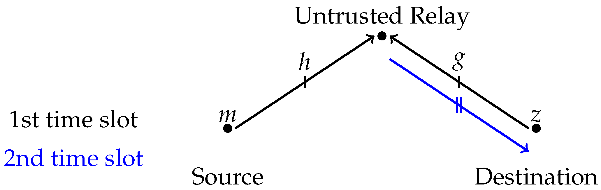
Figure 2.
The constellation diagram of square 16-QAM with Gray encoding. QAM: quadrature amplitude modulation.
Figure 2.
The constellation diagram of square 16-QAM with Gray encoding. QAM: quadrature amplitude modulation.

Figure 3.
Thresholds for phase selection: and .
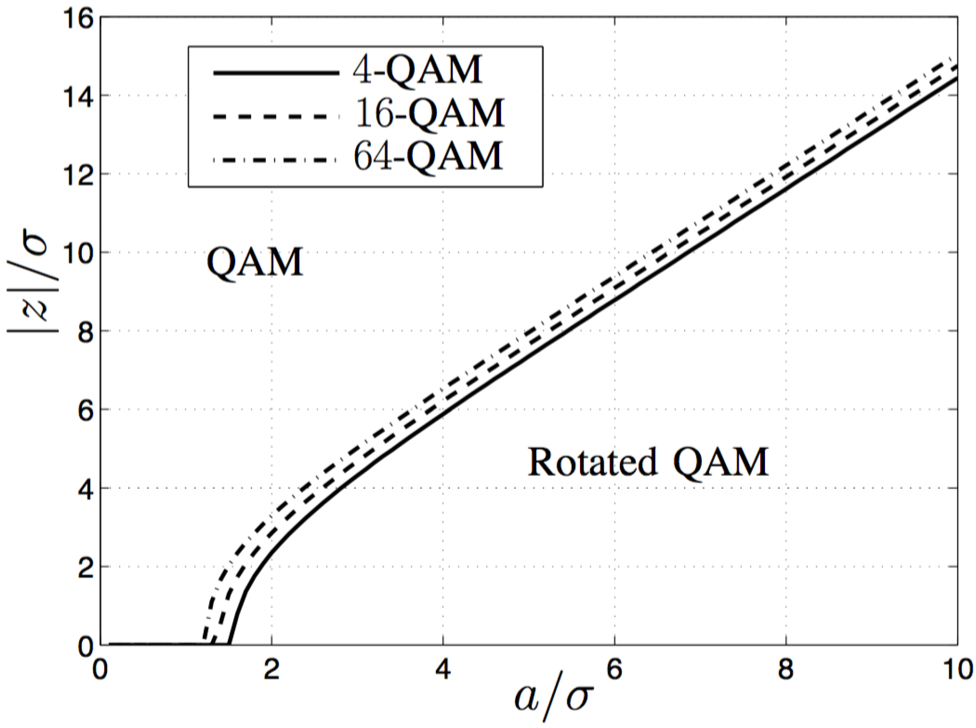
Figure 4.
Symbol error rate (SER) performance of 16–QAM modulation as a function of , where , , and .
Figure 4.
Symbol error rate (SER) performance of 16–QAM modulation as a function of , where , , and .

Figure 5.
SER performance of 16-QAM modulation as a function of without and with optimal , where dB, , and .
Figure 5.
SER performance of 16-QAM modulation as a function of without and with optimal , where dB, , and .
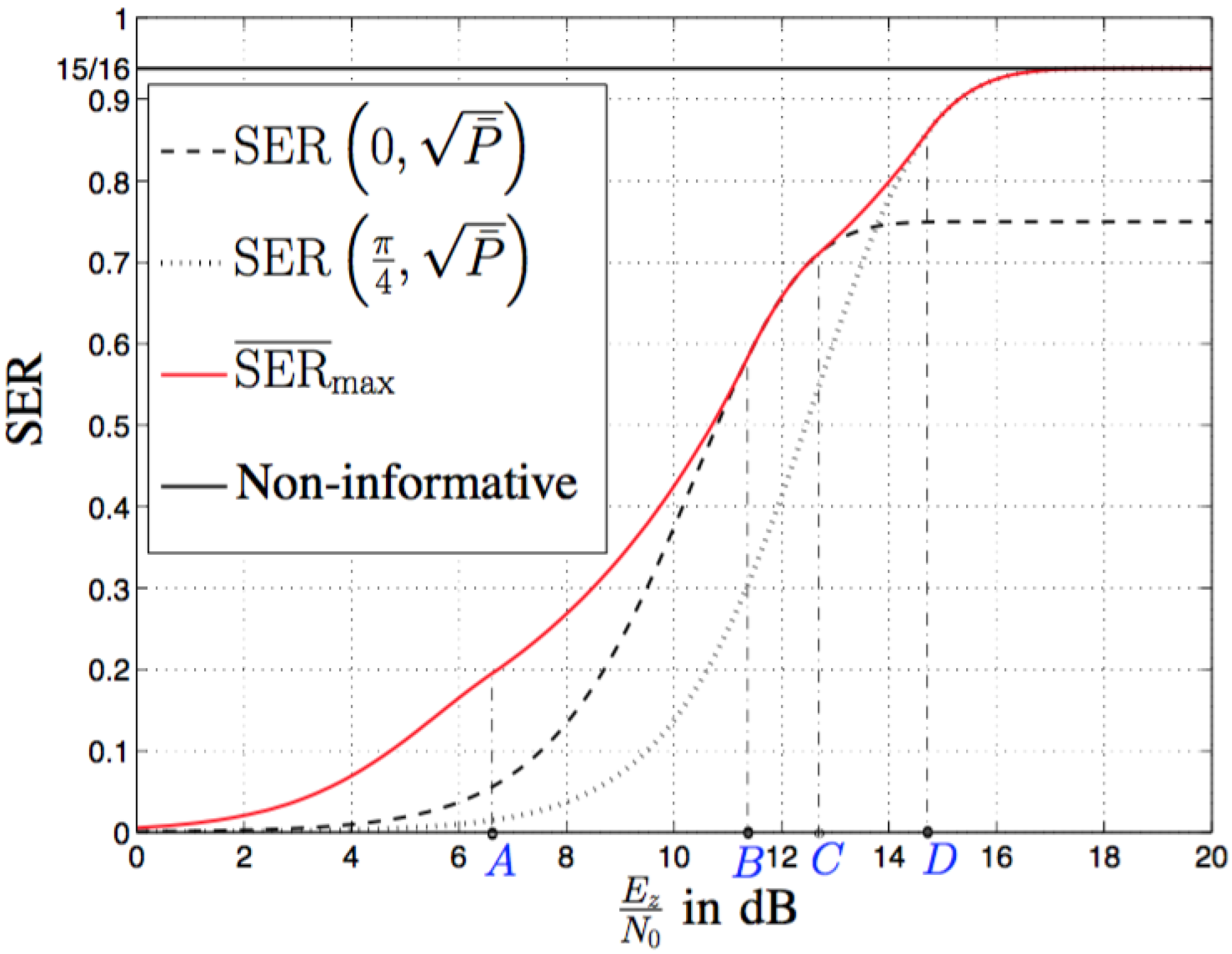
Figure 6.
Optimal amplitude distribution and the corresponding phase selection for 16-QAM modulation, where dB, , and .
Figure 6.
Optimal amplitude distribution and the corresponding phase selection for 16-QAM modulation, where dB, , and .

Figure 7.
Probability to transmit for 16-QAM modulation, dB, , and .
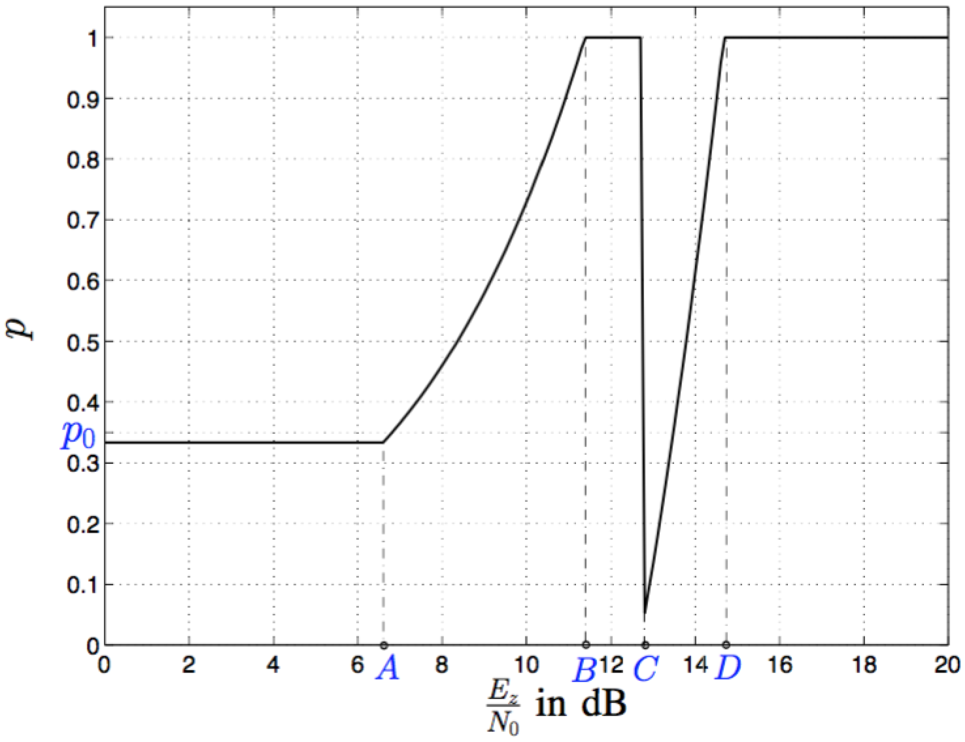
Figure 8.
SER performance of 4-QAM modulation as a function of , where dB, , and .

Figure 9.
SER performance of 16-QAM modulation as a function of , where dB, , and .

Figure 10.
ASER performance of 4-QAM and 16-QAM modulations as a function of , where dB, , and .

Figure 11.
ASER performance of 16-QAM modulation as a function of , where dB, , and .
© 2017 by the authors. Licensee MDPI, Basel, Switzerland. This article is an open access article distributed under the terms and conditions of the Creative Commons Attribution (CC BY) license (http://creativecommons.org/licenses/by/4.0/).
Share and Cite
MDPI and ACS Style
Liu, Y.; Li, L.; Alexandropoulos, G.C.; Pesavento, M. Securing Relay Networks with Artificial Noise: An Error Performance-Based Approach. Entropy 2017, 19, 384. https://doi.org/10.3390/e19080384
AMA Style
Liu Y, Li L, Alexandropoulos GC, Pesavento M. Securing Relay Networks with Artificial Noise: An Error Performance-Based Approach. Entropy. 2017; 19(8):384. https://doi.org/10.3390/e19080384
Chicago/Turabian StyleLiu, Ying, Liang Li, George C. Alexandropoulos, and Marius Pesavento. 2017. "Securing Relay Networks with Artificial Noise: An Error Performance-Based Approach" Entropy 19, no. 8: 384. https://doi.org/10.3390/e19080384
Note that from the first issue of 2016, this journal uses article numbers instead of page numbers. See further details here.