

Novel Schemes of No-Slip Boundary Conditions for the Discrete Unified Gas Kinetic Scheme Based on the Moment Constraints

1
Hypervelocity Aerodynamics Institute, China Aerodynamics Research and Development Center, Mianyang 621000, China
2
Laboratory of Aerodynamics in Multiple Flow Regimes, China Aerodynamics Research and Development Center, Mianyang 621000, China
3
School of Naval Architecture and Ocean Engineering, Huazhong University of Science and Technology, Wuhan 430074, China
*
Author to whom correspondence should be addressed.
Entropy 2023, 25(5), 780; https://doi.org/10.3390/e25050780
Submission received: 9 April 2023
/
Revised: 8 May 2023
/
Accepted: 9 May 2023
/
Published: 10 May 2023
(This article belongs to the Special Issue Kinetic Theory-based Methods in Fluid Dynamics II)
Abstract
:The boundary conditions are crucial for numerical methods. This study aims to contribute to this growing area of research by exploring boundary conditions for the discrete unified gas kinetic scheme (DUGKS). The importance and originality of this study are that it assesses and validates the novel schemes of the bounce back (BB), non-equilibrium bounce back (NEBB), and Moment-based boundary conditions for the DUGKS, which translate boundary conditions into constraints on the transformed distribution functions at a half time step based on the moment constraints. A theoretical assessment shows that both present NEBB and Moment-based schemes for the DUGKS can implement a no-slip condition at the wall boundary without slip error. The present schemes are validated by numerical simulations of Couette flow, Poiseuille flow, Lid-driven cavity flow, dipole–wall collision, and Rayleigh–Taylor instability. The present schemes of second-order accuracy are more accurate than the original schemes. Both present NEBB and Moment-based schemes are more accurate than the present BB scheme in most cases and have higher computational efficiency than the present BB scheme in the simulation of Couette flow at high Re. The present Moment-based scheme is more accurate than the present BB, NEBB schemes, and reference schemes in the simulation of Poiseuille flow and dipole–wall collision, compared to the analytical solution and reference data. Good agreement with reference data in the numerical simulation of Rayleigh–Taylor instability shows that they are also of use to the multiphase flow. The present Moment-based scheme is more competitive in boundary conditions for the DUGKS.
1. Introduction
Discrete Unified Gas Kinetic Scheme (DUGKS) for all Knudsen Number Flows was proposed [1], which combined the advantages of the Lattice Boltzmann method (LBM) and the Unified Gas Kinetic Scheme (UGKS). The DUGKS and LBM can share the same equilibrium distribution function, and both start from the Boltzmann equation. Although the computational time cost of DUGKS is slightly higher than that of LBM in a continuous flow, the numerical stability of DUGKS is better than that of LBM, and it can capture flow characteristics that LBM is not competent to [2,3]. Both DUGKS and UGKS have asymptotic preserving properties, where the time step is not limited by the collision time. For the reconstruction of cell-interface flux, the UGKS adopts the analytical time-evolved integral solution and the DUGKS adopts a simpler numerical characteristic solution, in which the calculation time cost is approximately 70% of that in the UGKS [4]. In short, the DUGKS has a simple framework and the powerful ability to capture the flow characteristics in a wide flow regime, which can make the DUGKS a competitive tool in comparison with LBM and UGKS. Recently, the DUGKS has been successfully applied to a variety of flow problems in different flow regimes, such as turbulent flows [5,6,7,8], micro flows [9,10,11,12,13], compressible flows [4,14,15,16,17], multiphase flows [18,19,20], fluid-particle flows [21,22], flows with complex geometries [23,24], gas mixture systems [25,26], pore-scale porous media flows [27], and plasma physics [28,29]. In addition to flow problems, the DUGKS was also extended to multiscale transport problems such as phonon heat transfer [30,31,32] and the radiation of photons [33,34].
The boundary conditions are crucial for numerical methods [35,36,37]. If boundary conditions are not properly introduced in the numerical methods, severe problems may arise, such as the divergence of numerical solutions. In short, boundary conditions should be treated with great care. Because the LBM and DUGKS share a common kinetic origin, researchers tried to introduce the boundary conditions from the LBM into the DUGKS. For example, two kinds of no-slip boundary conditions are widely used: The bounce-back (BB) scheme [1] and the non-equilibrium bounce-back (NEBB) scheme [38]. They have received considerable critical attention. For the LBM and DUGKS, there are distinctive modeling differences in the particle evolution process. The LBM separates the particle streaming and collision process. However, particle transport and collision are fully coupled in DUGKS. This dynamic difference can result in the deviation of the boundary condition in the LBM and DUGKS. For example, the boundary condition is processed at time t + 0.5Δt in the DUGKS but at time t in the LBM. Yang et al. [39] have analyzed and assessed the BB scheme and the NEBB scheme for the DUGKS. Although the BB scheme is a simple and common method to apply the no-slip boundary condition, it introduces an additional error (a purely artificial numerical slip error) into the DUGKS. The NEBB scheme eliminates the error of the numerical slip, but the closure to find the unknowns at the wall is somewhat arbitrary [40]. There are only a few studies on boundary conditions for the DUGKS, which have not been studied thoroughly. So, it can bring renewed interest and value to introduce and test other boundary conditions for the DUGKS.
Recently, the moment-based boundary condition has received increased interest and attention [40,41,42,43,44,45], which is based on the moments of the LBM [40] and has not yet been introduced to the DUGKS. Numerical simulations show that the moment-based boundary condition converges with second-order accuracy using dipole–wall collisions [40], natural convection in the square cavity [41], and lid-driven cavity flow [43,44,45]. A numerical simulation of the Poiseuille flow shows that the moment-based boundary condition can eliminate the spurious oscillations seen in solutions using other boundary conditions, considering the nonzero deviatoric stress [42]. The moment-based boundary condition can be parallelized easily for efficient computing, and it is conceptually simpler and more straightforward than other methods that involve a mixture of the bounce-back rule, hydrodynamic moments, momentum corrections, and other modifications to the distribution functions [44].
To the best of the authors’ knowledge, the moment-based boundary condition for the DUGKS has not been analyzed. So, the present work introduces the moment-based boundary condition to the DUGKS, and its numerical performance is studied in comparison with the BB scheme and the NEBB scheme. Generally, for boundary conditions in the DUGKS, the boundary nodes are located at the cell interface, and the unknown original distribution functions are treated at time tn+1/2 = tn + 0.5Δt [39]. In the DUGKS, the original distribution functions are obtained after the transformed distribution functions are calculated. So, in this study, novel schemes of the BB, NEBB, and Moment-based boundary conditions are proposed for the DUGKS, which treat the unknown transformed distribution functions at time tn+1/2 = tn + 0.5Δt. That is, the implementation of the boundary condition shifts from the original (xw, ξα, t + h) to the transformed (xw, ξα, t + h), which may improve the numerical performance.
Assessment and validation of the novel schemes are necessary and important to their application. To test boundary conditions for the DUGKS, numerical simulations have only focused on the Couette flow and the Poiseuille flow in Ref. [39]. Considering the generality, more complex flows should be adopted to test boundary conditions, such as the multiphase flow. The multiphase flows are of both academic and industrial interest [46,47,48,49,50,51,52], such as the unsteady Rayleigh–Taylor instability. The benchmark problem of Rayleigh–Taylor instability has been used to validate the newly developed numerical approaches [18,19,50,51]. The bounce-back boundary conditions are applied to the bottom and top wall boundaries in the DUGKS simulations of Rayleigh–Taylor instability [18]. However, to the best of the authors’ knowledge, the effect of varied wall boundary conditions on the numerical simulation of Rayleigh–Taylor instability has been not investigated. Therefore, in this work, the unsteady Rayleigh–Taylor instability is used to test and validate the proposed schemes of boundary conditions, in addition to the Couette flow, the Poiseuille flow, the dipole–wall collision, and the lid-driven cavity flow.
The rest of the paper is organized as follows. In Section 2, the DUGKS with a force term, the original and novel schemes of BB, NEBB, and Moment-based boundary conditions for the DUGKS are present. In Section 3, the boundary conditions are tested and assessed using Couette flow, Poiseuille flow, Lid-driven cavity flow, vortex dipole–wall collision, and Rayleigh–Taylor instability. In Section 4, the conclusions are drawn.
2. Numerical Method
It is noted that the present work is for isothermal continuum flow.
2.1. DUGKS with a Force Term
In the LBM, a modeled gas, which is composed of identical particles whose velocities are restricted to a finite set of vectors, is considered. Similar to the LBM, the DUGKS follows the lattice Boltzmann equation. It is inevitably necessary to introduce a force term to the DUGKS in some cases, such as the external force driven by Poiseuille flow. The governing equation of the DUGKS with a force term [3]:
Equation (1) describes the spatial and temporal evolution of the distribution f (ξα, x, t) of particles with velocity ξα at position x and time t. The fundamental variable in gas kinetic theory is the particle distribution function, which simultaneously represents the density of mass in both physical space and velocity space.
The commonly used Bhatnagar–Gross–Krook (BGK) model is given as
where τ denotes the relaxation time.
The force term is approximated as [3]
where a denotes the acceleration due to the external force, and R and T represent the gas constant and the temperature, respectively. For simplicity, the particle velocity ξ and the fluid velocity u have been normalized by , giving a sound speed of [53]. So, in the following simulations of isothermal continuum flow, the temperature T is constant with .
With the Taylor expansion at approximately zero particle velocity at a low Mach number, the Maxwellian equilibrium distribution function is approximated as [1]
The computational domain is divided into the cells Vi,j = ΔxiΔyj centered at (xi, yj) in the DUGKS with the D2Q9 model. As a finite volume scheme, the cell-averaged values of the distribution function and the force term are introduced, denoted as and ,
Integrating Equation (1) into each cell Vi,j from time tn = nΔt to time tn+1 = (n + 1)Δt, and using the midpoint rule and trapezoidal rule, the evolution equation of the DUGKS is advanced from tn to tn+1 as,
The scalar variable represents the flux across the cell interface, which is computed as
where f (ξα, xb, tn+1/2) represents the distribution at the cell interface xb at the time tn+1/2 = tn + h (h = Δt/2), and n is the outward unit vector normal to the surface ∂Vi,j.
For the purpose of eliminating the simplicity, new distribution functions are introduced:
The collision term can be expanded in the BGK collision model, and Equation (10) can be converted to the following equations:
The evolution equation of the DUGKS is simplified as
All other forms of the distribution function can be expressed in terms of in the DUGKS. So, we focus on the distribution function .
As can be seen from Equation (13), the critical step is to evaluate the interface flux .
For DUGKS with higher-order accuracy, more intermediate time steps can be selected, for example, the flux at the cell interface at t∗ = tn + ∆t/6 and t∗∗ = tn + 3∆t/4 need calculating [54]. Considering the easy implementation and fast computation in the present study, we select the intermediate time step in the present study. Equation (1) is integrated within a half time step (h = Δt/2) along the characteristic line using the trapezoidal rule to treat the collision and force terms, and we have
where xb at the cell interface denotes an end point along the characteristic line.
Similar to the above discussion, new distribution functions are introduced:
With new distribution functions, Equation (14) is simplified as
With the Taylor expansion [1], the right term of Equation (17) can be approximated as
where and its gradients can be approximated by linear interpolations. For the uniform mesh in the x-direction, e.g.,
The distribution function (ξα, x, tn) at the cell center can be calculated as
Then, can be obtained by using Equations (17) and (18).
Similarly, the original distribution function can be obtained from :
The equilibrium function at the cell interface can be determined by the conserved variables. Based on the conservation of mass and momentum, the density and velocity at the cell interface center can be given as
Finally, the flux is obtained by Equation (9) after is determined by Equation (15). Then, the tracked distribution function can be updated to the next time step by Equation (13).
Particularly, the following equation will be used in the DUGKS [3],
The density ρ and velocity u at the cell center can be calculated from :
In the present DUGKS, the relaxation time τ is computed from τ = ν/RT, where ν is the kinematic viscosity. The time step Δt is independent of the relaxation time τ for all flow regimes, and it is determined by the Courant–Friedrichs–Lewy (CFL) condition [55]:
where χ is the CFL number, Δx is the minimum grid spacing, and C is the maximum discrete velocity. We set C to be in the present work.
2.2. Original Schemes of No-Slip Boundary Conditions
The original schemes of BB, NEBB, and Moment-based boundary conditions are introduced, and they are analyzed theoretically from the view of the moment.
The boundary conditions are applied to solve the unknown distributions that have velocities pointing into the fluid domain. So, we need to find the unknown distributions.
2.2.1. Moment-Based Scheme
In brief, the Moment-based scheme states that the unknown distribution functions at the boundary can be determined by the linearly independent moments. For the D2Q9 model, there are nine discrete velocity moments, including the 6 hydrodynamic moments (the density ρ, momentum ρu, and momentum flux Π) and 3 non-hydrodynamic moments (Qxxy, Qxyy, and Sxxyy) [40]:
For the no-slip wall boundary, we pick three linearly independent moments (momentum Πx, Πy, and momentum flux Πxx), and impose constraints upon them, i.e., ux = uwx (const), uy = 0, ∂xux = 0 for the south boundary (uwy = 0). Then, by Chapman–Enskog, Πxx = Πxx(0) + τΠxx(1) = Πxx(0) = cs2ρ + ρux2, because Πxx(1) ≈ −2cs2ρ∂xux = 0. We obtain the following three conditions for three unknowns:
For the south boundary (uwy = 0), solving these equations yields
2.2.2. Non-Equilibrium Bounce Back Scheme
For the south boundary (uwy = 0), the Non-equilibrium Bounce-Back (NEBB) scheme can be expressed as [38]:
where uwx denotes the wall velocity in the x-direction.
It is found that the calculation of the density in Equation (28) is the same as that in Equation (29) when uwy = 0. Then, from a fresh perspective based on the moment, it is found that the conditions of the NEBB scheme are
That is, for the NEBB scheme, three linearly independent moments are picked for the south boundary: Momentum Πx, Πy, and momentum flux Qxxy. Πx and Πy are useful in defining the no-slip condition, but the condition on a component of the third-order moment Qxxy seems somewhat arbitrary.
2.2.3. Bounce-Back Scheme
The Bounce-Back (BB) scheme assumes that a particle just reverses its velocity after hitting the wall. The unknown distribution functions f (xw, ξα, tn+1/2) for particles leaving the wall are determined as [1],
where uw denotes the wall velocity and ρw denotes the density at the wall boundary, which can be approximated well by the constant average density for nearly incompressible flows [1].
For the south boundary (the wall velocity at y-direction uwy = 0), the unknown original distribution functions , , and are given as,
where uwx denotes the wall velocity in the x-direction.
For the BB scheme, three linearly independent moments are picked for the south boundary: Πy, Qxyy, and Qxxy, leading to the conditions on a moment basis,
Two components of the third-order moment Qxyy and Qxxy result in the numerical slip error.
2.3. Novel Schemes of No-Slip Boundary Conditions
In the DUGKS, new transformed distribution functions are introduced to evaluate the interface flux. So, the original scheme of boundary conditions should be transformed. The original distribution functions (xw, ξα, t + h) are obtained after the transformed distribution functions (xw, ξα, t + h) are calculated. So, the implementation of the boundary condition shifts from the original (xw, ξα, t + h) to the transformed (xw, ξα, t + h), which may improve the numerical performance. It is noted that the particle streaming and collision are fully coupled in the DUGKS.
As shown in Figure 1, in the present work, the boundary is located at a cell interface, and we treat the unknown distribution functions (xw, ξα, t + h) at the cell interface center xw. Owing to new distribution functions and force terms in the DUGKS, we should convert the original boundary conditions into a new format. The boundary conditions will be translated into constraints on (xw, ξα, t + h). It should noted that more details about derivations for the novel schemes are shown in Appendix A.
Considering Equation (21), we can obtain
With Equations (27), (35), and (36), the Moment-based scheme (Equation (28)) is rewritten as
In the Couette flow and lid-driven cavity flow, the top wall moves with the constant velocity U0 (ax = ay = 0, uwx = U0, uwy = 0, ∂xuwx = 0), and the unknowns at the north boundary can be written as
With Equations (30), (35), and (36), the NEBB scheme (Equation (29)) is rewritten as
With Equations (34) and (36), the BB scheme (Equation (33)) is rewritten as
2.4. Analysis of Numerical Slip Errors of Novel Schemes
In the following, the numerical slip errors () of the novel schemes of no-slip boundary conditions are theoretically analyzed.
Inspired by Guo et al. [56], He et al. [57], Wang et al. [58], and Yang et al. [59], the unidirectional steady flow is adopted to analyze the numerical error of boundary conditions. The assumptions in the unidirectional steady flow are written as
where denotes an arbitrary flow variable. ax and ay denote the component of the acceleration a in the x-direction and y-direction, respectively. Considering Equations (14) and (35), we can obtain
With the Maxwellian equilibrium distribution function known, as shown in Equation (4), we can obtain
Yang et al. [39] treated the unknown distribution functions f(xw, ξα, t + h) at the cell interface xw, and the numerical slip error of the BB scheme and NEBB scheme generated in the DUGKS can be written as
However, in the present work, we treat the unknown distribution functions (xw, ξα, t + h) at the cell interface center xw.
For the Moment-based scheme, we substitute Equation (37) into Equation (35), and obtain
For the NEBB scheme, we substitute Equation (39) into Equation (35), and obtain
For the BB scheme, we substitute Equation (40) into Equation (35), and obtain
With Equations (15) and (43), we can obtain
It is found that the numerical slip error of the BB scheme in the present work is also zero () when the acceleration ax is equal to 0.
As shown in Equation (34), the only hydrodynamic condition is that the flow rate through the wall is zero in the BB scheme, and the velocity along the wall is undefined. The BB scheme does not impose a boundary condition on the tangential velocity at the wall, resulting in the numerical slip velocity when the external force term exists. Both the NEBB scheme and Moment-based scheme select momentum Πx and Πy, which can satisfy the no-slip condition without generating numerical slip error. So, momentum Πx and Πy are useful in defining the no-slip condition. It seems sensible to choose the hydrodynamic moments instead of the non-hydrodynamic ones that do not appear in these equations of motion [40].
2.5. Explore Extending Present Schemes to Curved Boundaries
To extend the current boundary treatment to curved boundaries, this work also tries to introduce the methods from the LBM into the DUGKS, including the link method (Ladd [60,61]), interpolated methods (Bouzidi et al. [62], Yu et al. [63]), and single-node schemes (Zhao&Yong [64], Tao et al. [65], Zhao et al. [66], Chen et al. [67]). Although the LBM and DUGKS share a common kinetic origin, we need to be aware of distinctive features in the LBM and DUGKS. It should be noted that the present boundary conditions treat the unknown transformed distribution functions at the cell interface in the DUGKS.
2.5.1. Link Method
As shown in Figure 2, the link method approximates the curved solid boundary to a stair-like zigzag line (dash line), which is set in the center of the solid and fluid nodes (i.e., the cell interface). So, it is quite convenient for the DUGKS to apply the link method to treat the curved boundaries by treating the unknown transformed distribution functions (xw, ξα, t + h) at the cell interface center xw and at time tn+1/2 = tn + 0.5Δt (h = 0.5Δt). If the grid mesh is fine enough, it is easy and efficient to treat the curved boundaries by adopting the current boundary treatment (as shown in Section 2.3) directly.
2.5.2. Interpolated Method
In actuality, the link method makes the smooth curved boundary into the rough boundary. To improve the curved boundary conditions, some interpolated methods are developed. It should be noted that strategies to design interpolated schemes are not unique. For example, in the LBM, two representative interpolated bounce-back (IBB) schemes are the conditional scheme proposed by Bouzidi et al. [62] and the unified scheme by Yu et al. [63]. It is noted that the interpolated methods are based on the bounce-back scheme in the LBM. Similarly, the present BB scheme for the DUGKS can be applied to the interpolated methods. However, it needs more implementation effort or other strategies to extend the present NEBB scheme and Moment-based scheme to curved boundaries.
Conditional Scheme
Inspired by the conditional scheme [62], the IBB scheme in the DUGKS is proposed by using linear (first-order treatment) or quadratic (second-order treatment) interpolation formulas involving values at two or three nodes. The conditional scheme uses separate treatments for q < 0.5 and q ≥ 0.5 according to the scaled distance.
Taking the boundary configuration in Figure 3 as an example, we use quadratic interpolation to obtain,
When q = ½, the conditional interpolation formulas are reduced to the “bounce-back” scheme. Since a distribution function travels precisely one grid spacing from t to t + ∆t, particles that start from xf can end precisely at the same location only when xf is half a grid spacing from the wall.
Unified Scheme
Inspired by the unified scheme [63], the present work treats the curved boundaries in three main steps:
- ➀
- A virtual distribution function (xw, , t + h) is interpolated from the distribution functions at xf, xff and xfff. We use quadratic interpolation to obtain,
- ➁
- According to the current boundary treatment, the unknown distribution function (xw, , t + h) is obtained by using the known distribution function (xw, , t + h). All the present BB, NEBB, and Moment-based schemes (as shown in Section 2.3) are alternatives to calculate (xw, , t + h).
- ➂
- At last, we need to calculate the known distribution function (xf, , t + h), which is interpolated from (xw, , t + h), (xff, , t + h), (xfff, , t + h).
2.5.3. Single-Node Scheme
The interpolated methods [62,63] improve the accuracy to be second-order. However, they involve at least two neighboring fluid nodes, e.g., xf, xff, and xfff. It is inevitable to undermine the local computation property and further the parallel performance of LBM [68,69]. Moreover, the required number of fluid nodes may not be available for some cases, e.g., dense particle suspensions. Zhao and Yong (2017) [64] developed a single-node second-order bounce-back scheme for curved boundaries, which used pre- and post-collision density distributions to determine the unknown density distributions at the boundary. An alternative single-node second-order scheme was proposed by Tao et al. (2018) [65]. Zhao et al. (2020) [66] derived a general single-node second-order scheme for curved boundaries. However, the free parameter is limited within the range of [max(0, 2q − 1), 2q]. Later, it was reported that the free parameter γ can be arbitrarily chosen within the range of [0, 2q] in a general single-node second-order scheme proposed by Chen et al. (2021) [67], but γ should be normalized by the gird spacing ∆x. It should be noted that the single-node schemes [64,65,66,67] do not involve the present Moment-based scheme.
Inspired by Zhao and Yong (2017) [64], the present single-node second-order BB scheme in the DUGKS can be similarly expressed as,
where ρ0 represents the mean density.
Inspired by Tao et al. (2018) [65], the present single-node second-order NEBB scheme in the DUGKS can be similarly expressed as,
As shown in Equation (55), it is known that the distribution function at xff streams directly from xf. The distribution function at xw is divided into two parts of equilibrium and non-equilibrium, which are represented by the superscripts eq and neq, respectively.
For the equilibrium part at xw, it can be determined by the known velocity and the approximate fluid density, according to the Maxwellian equilibrium distribution function (Equation (4)). is approximated as
It has been demonstrated that for low-speed flow, using ρf (t) and ρf (t + h) to approximate ρf (t + h) and ρw (t + h) have second- and third-order accuracies, respectively [70].
For the non-equilibrium part, it can be approximated and calculated by the non-equilibrium distribution function at xf, with the idea of non-equilibrium bounce back [38,71]. is approximated as
is obtained having at least first-order accuracy, which is enough for deriving a second-order construction of [65]. Hence, the present single-node second-order NEBB scheme is second-order accurate in space theoretically.
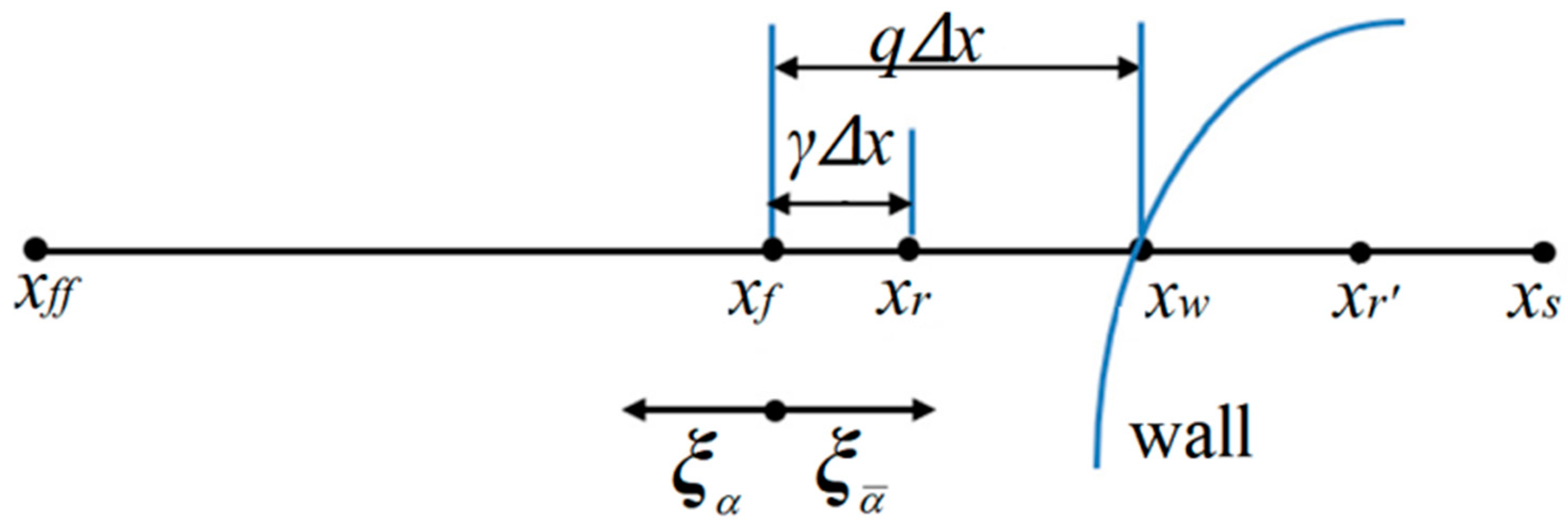
Inspired by Chen et al. (2021) [67], taking the boundary configuration in Figure 4 as an example, a general single-node second-order scheme for the DUGKS is expressed as
The constraint 1 < γ ≤ 2q is applied to ensure that both 1 + γ − 2q and 2q − γ are non-negative.
In future work, the present schemes for curved boundaries in the DUGKS will be further validated and analyzed by theoretical analysis and numerical tests.
3. Numerical Tests
We perform the numerical tests of the Couette flow, the Poiseuille flow, the Lid-driven cavity flow, and the Rayleigh–Taylor instability to further assess the proposed scheme of boundary conditions for the DUGKS. In our simulations, the CFL number is set to be 0.95, and Re = HU0/ν.
The convergence criterion for attaining the steady-state solution is
where represents the velocity in the fluid domain.
To assess the accuracy, we measure the L2 errors of steady velocity fields,
where is the analytical solution.
3.1. The Couette Flow
In the Couette flow, the top wall moves with the horizontal velocity U0 = 0.1, and the bottom wall is fixed. We apply the proposed scheme of boundary conditions to the top and bottom walls. The inlet and outlet adopt the periodic boundary condition. The gap between the top and bottom wall is set as H = 1. For the no-slip condition, the analytical solution of horizontal velocity in the Couette flow can be written as,
u(y)/U0 = y/H.
It is noted that the convergence criterion for simulating the Couette flow follows Equation (60). To test the accuracy, the L2 errors of horizontal velocity along the vertical center line are measured at Re = 100, 1000, and 10,000. The results are shown in Table 1, Table 2 and Table 3. Under different meshes (N × N, N = 16, 32, 64, 96, 128), the time step is set as Δt = 0.95√2/N = 0.08396893, 0.041984465, 0.020992233, 0.013994822, and 0.010496116, respectively.
As shown in Figure 5, Figure 6 and Figure 7, the present results agree very well with the analytic solution. As shown in Table 1, Table 2 and Table 3, the numerical errors are almost negligible, even with a coarse mesh (N = 8). It is shown that the BB scheme, NEBB scheme, and Moment-based scheme can accurately simulate the Couette flow with the no-slip condition. As shown in Table 1, Table 2 and Table 3, the L2 errors in the Moment-based scheme are equal to those in the NEBB scheme, which are a little less than those in the BB scheme at Re = 100.
To test the stability of the proposed scheme of boundary conditions at high Re, some simulations are performed at Re = 105, 106, and 107 with N = 16. The steps of reaching the steady state are shown in Table 4. It is found that both the NEBB scheme and thMoment-based scheme converge to the steady state faster than the BB scheme.
As shown in Table 5, the L2 error of the Moment-based scheme is equal to that of the NEBB scheme, and the L2 errors of the Moment-based scheme and the NEBB scheme are a little less than those in the BB scheme. The L2 errors are approximately 0.23%, 2.25%, and 18.6% at Re = 105, 106, and 107, respectively. It is shown that the schemes can predict acceptable results for the simulation of the Couette flow at high Re.
3.2. The Lid-Driven Cavity Flow
In the lid-driven cavity flow, the top wall moves with the horizontal velocity U0 = 0.1. The bottom wall and left- and right-side walls are fixed. The walls adopt the present boundary conditions. The cavity length L is set to be 1. It is noted that the convergence criterion for simulating the lid-driven flow follows Equation (60).
We perform some numerical simulations using the Moment-based scheme at Re = 400, 1000, 3200, 5000, 7500, and 10,000 with the different uniform meshes (N × N, N = 32, 64, 128, 256, and 512). The results of velocity profiles are present in Figure 8 and Figure 9. It is found that the results of the Moment-based scheme are in good agreement with the reference data [72] with a relatively fine mesh (N = 128, 256, 512).
To compare the Moment-based scheme with the BB and NEBB scheme, some simulations are performed at Re = 100, 400, 1000, 3200, 5000, 7500, and 10,000 with the fine mesh (N = 256). The results of velocity profiles are present in Figure 10 and Figure 11. It is shown that the results of the Moment-based, BB, and NEBB schemes are all in good agreement with the reference data [72]. Based on a comparison with the reference data, the proposed schemes of the boundary conditions for the DUGKS are valid and suitable for simulating the lid-driven cavity flow.
3.3. The Poiseuille Flow
The Poiseuille flow is driven by an external force ρax with periodic boundary conditions at the entrance and exit. Both the top and bottom walls adopt the proposed scheme of boundary conditions. The gap between the top and bottom wall is set as H = 1. For the no-slip condition, the analytical solution of horizontal velocity in the Poiseuille flow can be expressed as,
where Umax = axH2/8ν.
u(y)/Umax = 4y/H(1 – y/H),
It is noted that ay = 0 and the convergence criterion for simulating the Poiseuille flow follows Equation (60). In this subsection, it is noted that the “Original” scheme represents the boundary condition with ax = ay = 0 in Equation (37) or Equation (39), and the “Present” scheme represents the proposed scheme of boundary condition with ax = g, ay = 0 in Equation (37) or Equation (39).
To compare the present NEBB scheme (such as Equation (39) with ax = g, ay = 0) with the original NEBB scheme (such as Equation (39) with ax = ay = 0), the original NEBB scheme is also applied to both the top and bottom walls. The results are shown in Figure 12, Figure 13 and Figure 14 and Table 6.
As shown in Figure 12, Figure 13 and Figure 14, it seems that both the present and original NEBB schemes agree very well with the analytical solution with N = 32, 64, and 128 at Re = 100, 1000, and 10,000. Furthermore, the L2 errors of horizontal velocity are measured. As shown in Table 6, the L2 error of the present NEBB scheme is less than the original NEBB scheme, which shows the present NEBB scheme is more accurate than the original NEBB scheme. It is found that the present and original NEBB schemes are almost second-order accurate.
To compare the present Moment-based scheme (such as Equation (37) with ax = g, ay = 0) with the original Moment-based scheme (such as Equation (37) with ax = ay = 0), the original Moment-based scheme is also applied to both top and bottom walls. The results are shown in Figure 15, Figure 16 and Figure 17 and Table 7.
As shown in Figure 15, Figure 16 and Figure 17, it seems that both the present and original Moment-based schemes agree very well with the analytical solution with N = 32, 64, and 128 at Re = 100, 1000, and 10,000. Furthermore, the L2 errors of horizontal velocity are measured. As shown in Table 7, the L2 error of the present Moment-based scheme is less than the original Moment-based scheme, which shows the present Moment-based scheme is more accurate than the original Moment-based scheme. It is found that the present and original Moment-based schemes are almost second-order accurate.
Comparing Table 6 with Table 7, it is found that the original Moment-based scheme is more accurate than the original NEBB scheme under different meshes, and the present Moment-based scheme is more accurate than the present NEBB scheme with N = 16 and 32, in contrast to the cases with N = 64 and 128.
To compare the present BB and original and present NEBB and Moment-based schemes with the BB and NEBB schemes proposed by Yang et al. [39], we show the L2 errors in Table 8.
As shown in Table 8, the original and present schemes can predict more accurate results with a finer mesh. The L2 errors of the present BB and original and present NEBB schemes are not very sensitive to the meshes, but the L2 errors of the original and present Moment-based schemes are sensitive to the meshes. The L2 errors of the present BB and original and present Moment-based schemes are not very sensitive to the kinematic viscosity, but the L2 errors of the original and present NEBB schemes are very sensitive to the kinematic viscosity. The L2 errors of the original NEBB scheme are more than those of the present NEBB scheme, which are more than those of the NEBB scheme in Ref. [39]. With a fixed kinematic viscosity and grid number, the L2 errors of the present Moment-based scheme are minimal.
3.4. Normal Dipole–Wall Collision
Two counter-rotating vortices are propelled towards a solid boundary, and they collide with the no-slip boundary. The vortex dipole–wall collision is found in nature, such as the effect of the ground on the formulation of secondary vortices when an airplane takes off or lands [73]; another natural phenomenon is the formulation of large-scale vortices in geophysical turbulence on the coasts of seas and oceans [74]. Therefore, the vortex dipole–wall collision is an important problem.
In this study, two counter-rotating vortices are confined to a square box with a size of [−1, 1] × [−1, 1]. The present boundary conditions are applied to the no-slip walls. The initial vortex is located at positions (x1, y1) and (x2, y2). The initial velocities are
The symbol r0 denotes the radius of the monopoles, and We represents the strength of the vortices. To compare the numerical results, the total kinetic energy E(t) and the total enstrophy Ω(t) are calculated
where ω is the vorticity.
Clercx and Bruneau [75] simulated a dipole–wall collision using a Finite Difference Method (FDM) and the Chebyshev Pseudospectral Method (CPM). Mohammed et al. [40] simulated the dipole–wall collision using the LBM with two relaxation time models (TRT-LBM). Their authoritative data will be used as benchmark numerical results. For a direct comparison between the present work and the work of Ref. [40] and Ref. [75], we use the grid number (N) in the DUGKS as follows: Re = 625 (N = 1024), Re = 1250 (N = 1536), Re = 2500 (N = 2048) and Re = 5000 (N = 3072).
In the dipole–wall collision benchmark test for the normal case, two monopoles are located at positions (x1, y1) = (0, 0.1) and (x2, y2) = (0, −0.1) initially. Then they are propelled towards the right wall. To test the effect of the present schemes on the vortices after the dipole collides, vorticity contour plots are present in Figure 18, Figure 19, Figure 20 and Figure 21. As shown in vorticity contour plots, the present schemes are effective to simulate the dipole–wall collision, but the results with BB, NEBB, and Moment schemes are almost indistinguishable. To analyze the present schemes quantitatively, the values of the first and second maxima enstrophy of dipoles will be grouped for comparisons.
The present results for the first and second local maxima of the enstrophy are shown in Table 9 and Table 10, and we compare them with the results in Refs. [40,75]. The results computed using the moment-based boundary condition with DUGKS and TRT-LBM are in good agreement. However, the data obtained by the DUGKS appear to be more accurate than the data obtained by the TRT-LBM in the sense that the data are in closer agreement with the data obtained by FDM and CPM. The data obtained using the present moment-based scheme appear to be more accurate than the data obtained using the present BB and NEBB schemes in the sense that they are in closer agreement with the data obtained by FDM and CPM. These show that the proposed moment-based scheme can be a competitive method and gives us the confidence to use it to impose physically more complex conditions.
For further comparison with reference data [76], we present the values of the energy E(t) and enstrophy Ω(t) at different times, as shown in Table 11 and Table 12. The results obtained by the D3Q19-CM-LBM [76] show a slight mismatch (up to 3%) with respect to the LBM study by Mohammed et al. [40]. It should be noted that the results obtained by the DUGKS with the present Moment scheme are closer to the reference ones by Clercx and Bruneau [75] than those obtained by the TRT-LBM with the Moment scheme [40]. We address this behavior regarding the adoption in the present work of a more accurate boundary condition.
3.5. Rayleigh–Taylor Instability
Rayleigh–Taylor instability can occur when a layer of heavy fluid descends as light fluid below it rises. We perform a simulation using the same parameters as the first case of Re = 256, as shown in Figure 7.4 in Ref. [77]. The left and right boundaries adopt the periodic boundary conditions. For the upper and lower boundaries, the mentioned boundary conditions are applied. A computational domain X × Y = 128 × 512 is employed.
Initially, there is a zero-velocity field, and the location of the perturbed interface is set as y = 0.5Y + 0.1Xcos(2πx/X), where x, y, X, and Y are all in lattice units. We set the densities of heavy fluid and light fluid to be ρh = 0.12 and ρl = 0.04, respectively, so that At = (ρh − ρl)/(ρh + ρl) = 0.5. We set U = 0.04, and the gravitational acceleration is g = U2/X = 1.25 × 10⁻⁵ in the -y direction.
In this study, the HCZ model [52] is introduced for the DUGKS to simulate the Rayleigh–Taylor instability. In the model, two distribution functions satisfy the following equations:
The distribution functions g and f, corresponding to the density ρ and phase order ϕ, denote the particle distribution function in terms of position x, discrete particle velocity ξα, and time t. The relaxation times τg and τf are related to the viscosity and the mobility coefficient in the Cahn–Hilliard equation. Usually, we set τg = τf.
Sg and Sf represent the source terms, which can be written as
Fs represents the force associated with surface tension,
where the parameter κ determines the strength of surface tension and κ = 0.01 in our simulations.
In our simulations, a = 12RT, b = 4.
The equilibrium distributions geq and feq can be calculated as
Since Equations (66) and (67) share the same format as Equation (1), we will not repeat the detailed depiction of evolution in the DUGKS. In this subsection, we study the effect of varied boundary conditions on the numerical simulation results of Rayleigh–Taylor instability.
The results of varied boundary conditions at Re = 256 are shown in Figure 22, Figure 23, Figure 24, Figure 25, Figure 26 and Figure 27. Fifteen equal-interval contours ρ = 0.045, 0.05, 0.055, …, 0.115 are drawn in each figure. In this subsection, it is noted that the “Original” scheme represents the boundary condition with ax = ay = 0 in Equation (37) or Equation (39), and the “Present” scheme represents the proposed scheme of the boundary condition with ax = 0, ay = -g in Equation (37) or Equation (39).
As shown in Figure 22, Figure 23, Figure 24, Figure 25, Figure 26 and Figure 27, the fluid interface does not diffuse in our simulations by applying the mentioned boundary conditions. Compared to Figure 7.4 in Ref. [77], the evolution of the interface is indistinguishable from the results computed on the same mesh. It is shown that the present schemes are accurate and stable to simulate the Rayleigh–Taylor instability.
Figure 28 and Figure 29 show the density and vertical velocity profiles across the spike, respectively. As shown in Figure 28 and Figure 29, the interface thickness takes approximately four grid spacings (y = 31, 32, 33, and 34). There exist some “jiggles” near the interface, and the “jiggles” are different due to using different boundary conditions. From the magnified view in Figure 28 and Figure 29, the density and absolute value of vertical velocity near the interface using present NEBB and Moment-based schemes are less than that using BB, original NEBB, and original Moment-based schemes. Although the interface thickness is not affected by different boundary conditions, choosing a wall boundary condition can influence the density and velocity near the interface. Usually, numerical instability occurs near the interface. So, the finding reminds us that wall boundary conditions should be treated with care.
The simulation is executed on a Win10 X64 system with Intel(R) Core(TM) i5-8250U CPU (1.60 GHz)s. For comparison, the convergence error and CPU time at the last time step are recorded in Table 13. As shown in Table 13, the error and CPU time of the present Moment-based scheme are minimal, although they are almost indistinguishable.
4. Conclusions
Owing to the DUGKS with transformed distribution functions and force terms, we should convert the original boundary conditions into a new format. In this study, the proposed schemes of the BB, NEBB, and Moment-based boundary conditions are proposed for the DUGKS. The boundary conditions will be translated into constraints on the unknown transformed distribution functions at a half time step (t + 0.5Δt). The present work tests and analyzes, for the first time, the Moment-based scheme for the DUGKS. The mentioned boundary conditions are evaluated through theoretical analysis and numerical tests.
Using the steady unidirectional flow, we theoretically analyze the numerical slip error of the present BB, NEBB, and Moment-based schemes. It is found that the numerical slip errors of both NEBB and Moment-based schemes are equal to zero, which implements the no-slip condition at the wall boundary.
The accuracy and stability of the present schemes are validated by numerical tests of Couette flow, Poiseuille flow, Lid-driven cavity flow, normal dipole–wall collision, and Rayleigh–Taylor instability. The following conclusions are obtained:
- (1)
- Couette flow
The present schemes can predict accurate results of simulating the Couette flow, even with a coarse mesh for a large Reynolds number (Re = 106). The L2 errors in both NEBB and Moment-based schemes are equal, which are a little less than those in the BB scheme at Re = 100 under different meshes. Both the NEBB and Moment-based schemes are more accurate and converge to the steady state faster than the BB scheme at high Re (Re = 100,000, 1,000,000, and 10,000,000).
- (2)
- Lid-driven cavity flow
The present schemes can predict accurate results by simulating the lid-driven cavity flow. It is found that the results of the BB scheme are in better agreement with the reference data than those of Moment and NEBB schemes at Re = 10,000.
- (3)
- Poiseuille flow
The results of the present schemes agree very well with the analytical solution under different meshes (N = 32, 64, 128) at Re = 100, 1000, and 10,000. The L2 errors of the present NEBB and Moment-based schemes are less than the original NEBB and Moment-based schemes, respectively, which shows the present schemes are more accurate than the original schemes. It is found that the present schemes for the DUGKS are second-order accurate. The original Moment scheme is more accurate than the original NEBB scheme under different meshes. The present Moment scheme is more accurate than the present NEBB scheme with N = 16 and 32, in contrast to the cases with N = 64 and 128. Compared with the BB and NEBB schemes in Ref. [39], the L2 errors of the present Moment-based scheme are minimal.
- (4)
- Normal dipole–wall collision
With the present moment-based scheme, the DUGKS appears to be more accurate than the TRT-LBM. The data obtained by using the present moment-based scheme appears to be more accurate than the data obtained by using the present BB and NEBB schemes in the sense that they are in closer agreement with the benchmark data. These show that the proposed moment-based scheme can be a competitive method.
- (5)
- Rayleigh–Taylor instability
The present results agree well with the reference results, which show the present schemes can effectively capture the evolution of the interface. It is found that the error and CPU time of the present Moment-based scheme are minimal among the mentioned boundary conditions. The Rayleigh–Taylor instability simulation shows that choosing a wall boundary condition can influence the density and velocity near the interface slightly.
Author Contributions
Conceptualization, W.G.; Methodology, W.G.; Software, W.G.; Validation, W.G. and G.H.; Formal analysis, W.G. and G.H.; Investigation, W.G.; Resources, G.H.; Data curation, W.G.; Writing—original draft, W.G.; Writing—review & editing, W.G. and G.H.; Visualization, W.G.; Supervision, G.H.; Project administration, G.H.; Funding acquisition, G.H. All authors have read and agreed to the published version of the manuscript.
Funding
This work was supported by the National Natural Science Foundation of China [grant number 51979115 and grant number 51679099].
Institutional Review Board Statement
Not applicable.
Data Availability Statement
The data that support the findings of this study are available within the article.
Conflicts of Interest
The authors declare that they have no known competing financial interests or personal relationships that could have appeared to influence the work reported in this paper.
Appendix A. Derivations for the Novel Schemes
Here the derivation process of the moment constraints that the transformed distribution functions obeys i the present schemes is shown.
For the south boundary (uwy = 0), the unknown distribution functions are , , and .
In the moment-based scheme, the moment constraints are:
With the force term, expanding the density and the moment constraints (A1) yields the system:
Putting all the unknowns on the left-hand side, the system of equations takes the following form:
Solving the system (A3) yields the unknown distribution functions in the moment-based scheme:
In the NEBB scheme, the moment constraints are:
With the force term, expanding the density and the moment constraints (A5) yields the system:
Putting all the unknowns on the left-hand side, the system of equations takes the following form:
Solving the system (A7) yields the unknown distribution functions in the NEBB scheme:
In the BB scheme, the moment constraints are:
With the force term, expanding the density and the moment constraints (A9) yields the system:
Putting all the unknowns on the left-hand side, the system of equations takes the following form:
Solving the system (A11) yields the unknown distribution functions in the BB scheme:
References
- Guo, Z.; Xu, K.; Wang, R. Discrete Unified Gas Kinetic Scheme for All Knudsen Number Flows: Low-Speed Isothermal Case. Phys. Rev. E 2013, 88, 033305. [Google Scholar] [CrossRef] [PubMed]
- Wang, P.; Zhu, L.; Guo, Z.; Xu, K. A Comparative Study of LBE and DUGKS Methods for Nearly Incompressible Flows. Commun. Comput. Phys. 2015, 17, 657–681. [Google Scholar] [CrossRef]
- Wu, C.; Shi, B.; Chai, Z.; Wang, P. Discrete Unified Gas Kinetic Scheme with A Force Term For Incompressible Fluid Flows. Comput. Math. Appl. 2016, 71, 2608. [Google Scholar] [CrossRef]
- Guo, Z.; Wang, R.; Xu, K. Discrete Unified Gas Kinetic Scheme for all Knudsen Number Flows. II. Thermal Compressible Case. Phys. Rev. E 2015, 91, 033313. [Google Scholar] [CrossRef]
- Wang, P.; Wang, L.P.; Guo, Z. Comparison of the lattice Boltzmann equation and discrete unified gas-kinetic scheme methods for direct numerical simulation of decaying turbulent flows. Phys. Rev. E 2016, 94, 043304. [Google Scholar] [CrossRef]
- Bo, Y.; Wang, P.; Guo, Z.; Wang, L.P. DUGKS simulations of three-dimensional Taylor-Green vortex flow and turbulent channel flow. Comput. Fluids 2017, 155, 9–21. [Google Scholar] [CrossRef]
- Wang, L.P.; Huq, P.; Guo, Z. Simulations of turbulence and dispersion in idealized urban canopies using a new kinetic scheme. In Proceedings of the 68th Annual Meeting of the APS Division of Fluid Dynamics, Boston, MA, USA, 22–24 November 2015. [Google Scholar]
- Wen, X.; Wang, L.P.; Guo, Z.L.; Zhakebayev, D.B. Laminar to turbulent flow transition inside the boundary layer adjacent to isothermal wall of natural convection flow in a cubical cavity. Int. J. Heat Mass Transf. 2021, 167, 120822. [Google Scholar] [CrossRef]
- Zhu, L.; Guo, Z. Numerical study of nonequilibrium gas flow in a microchannel with a ratchet surface. Phys. Rev. E 2017, 95, 023113. [Google Scholar] [CrossRef]
- Zhu, L.; Yang, X.; Guo, Z. Thermally induced rarefied gas flow in a three-dimensional enclosure with square cross-section. Phys. Rev. Fluids 2017, 2, 123402. [Google Scholar] [CrossRef]
- Wang, P.; Ho, M.T.; Wu, L.; Guo, Z.; Zhang, Y. A comparative study of discrete velocity methods for low-speed rarefied gas flows. Comput. Fluids 2018, 161, 33–46. [Google Scholar] [CrossRef]
- Zhu, L.; Guo, Z. Application of discrete unified gas kinetic scheme to thermally induced nonequilibrium flows. Comput. Fluids 2019, 193, 103613. [Google Scholar] [CrossRef]
- Wang, Y.; Liu, S.; Zhuo, C.S.; Zhong, C.W. Investigation of nonlinear squeeze-film damping involving rarefied gas effect in micro-electro-mechanical systems. Comput. Math. Appl. 2022, 114, 188–209. [Google Scholar] [CrossRef]
- Wang, L.P.; Guo, Z.; Wang, J. Improving the discrete unified gas kinetic scheme for efficient simulation of three-dimensional compressible turbulence. In Proceedings of the 71st Annual Meeting of the APS Division of Fluid Dynamics, Atlanta, Georgia, 18–20 November 2018. [Google Scholar]
- Chen, T.; Wen, X.; Wang, L.P.; Guo, Z.; Wang, J.; Chen, S. Simulation of three-dimensional compressible decaying isotropic turbulence using a redesigned discrete unified gas kinetic scheme. Phys. Fluids 2020, 32, 125104. [Google Scholar] [CrossRef]
- Wen, X.; Wang, L.P.; Guo, Z.L. Designing a consistent implementation of the discrete unified gas-kinetic scheme for the simulation of three-dimensional compressible natural convection. Phys. Fluids 2021, 33, 046101. [Google Scholar] [CrossRef]
- Chen, T.; Wen, X.; Wang, L.P.; Guo, Z.L.; Wang, J.C.; Chen, S.Y.; Zhakebayev, D.B. Simulation of three-dimensional forced compressible isotropic turbulence by a redesigned discrete unified gas kinetic scheme. Phys. Fluids 2022, 34, 025106. [Google Scholar] [CrossRef]
- Zhang, C.H.; Yang, K.; Guo, Z. A discrete unified gas-kinetic scheme for immiscible two-phase flows. Int. J. Heat Mass Transf. 2018, 126, 1326–1336. [Google Scholar] [CrossRef]
- Yang, Z.; Zhong, C.; Zhuo, C. Phase-field method based on discrete unifified gas-kinetic scheme for large-density-ratio two-phase flows. Phys. Rev. E 2019, 99, 043302. [Google Scholar] [CrossRef]
- Zhang, C.; Liang, H.; Guo, Z.; Wang, L.-P. Discrete unified gas-kinetic scheme for the conservative Allen-Cahn equation. Phys. Rev. E 2022, 105, 045317. [Google Scholar] [CrossRef]
- Tao, S.; Zhang, H.; Guo, Z.; Wang, L.P. A combined immersed boundary and discrete unified gas kinetic scheme for particle-fluid flows. J. Comput. Phys. 2018, 375, 498–518. [Google Scholar] [CrossRef]
- Tao, S.; Chen, B.; Yang, X.; Huang, S. Second-order accurate immersed boundary-discrete unified gas kinetic scheme for fluid-particle flows. Comput. Fluids 2018, 165, 54–63. [Google Scholar] [CrossRef]
- Tao, S.; He, Q.; Wang, L.; Chen, B.; Chen, J.; Lin, Y. Discrete unified gas kinetic scheme simulation of conjugate heat transfer problems in complex geometries by a ghost-cell interface method. Appl. Math. Comput. 2021, 404, 126228. [Google Scholar] [CrossRef]
- He, Q.; Tao, S.; Yang, X.; Lu, W.; He, Z. Discrete unified gas kinetic scheme simulation of microflows with complex geometries in Cartesian grid. Phys. Fluids 2021, 33, 042005. [Google Scholar] [CrossRef]
- Zhang, Y.; Zhu, L.; Wang, R.; Guo, Z. Discrete unified gas kinetic scheme for all Knudsen number flows. III. Binary gas mixtures of Maxwell molecules. Phys. Rev. E 2018, 97, 053306. [Google Scholar] [CrossRef]
- Zhang, Y.; Zhu, L.; Wang, P.; Guo, Z. Discrete unified gas kinetic scheme for flows of binary gas mixture based on the McCormack model. Phys. Fluids 2019, 31, 017101. [Google Scholar] [CrossRef]
- Tao, S.; Wang, L.; Ge, Y.; He, Q. Application of half-way approach to discrete unified gas kinetic scheme for simulating pore-scale porous media flows. Comput. Fluids 2021, 214, 104776. [Google Scholar] [CrossRef]
- Liu, H.; Quan, L.; Chen, Q.; Zhou, S.; Cao, Y. Discrete unified gas kinetic scheme for electrostatic plasma and its comparison with the particle-in-cell method. Phys. Rev. E 2020, 101, 43307. [Google Scholar] [CrossRef]
- Liu, H.; Shi, F.; Wan, J.; He, X.; Cao, Y. Discrete unified gas kinetic scheme for a reformulated BGK-Vlasov-Poisson system in all electrostatic plasma regimes. Comput. Phys. Commun. 2020, 255, 107400. [Google Scholar] [CrossRef]
- Guo, Z.; Xu, K. Discrete unified gas kinetic scheme for multiscale heat transfer based on the phonon Boltzmann transport equation. Int. J. Heat Mass Transf. 2016, 102, 944–958. [Google Scholar] [CrossRef]
- Zhang, C.; Guo, Z. Discrete unified gas kinetic scheme for multiscale heat transfer with arbitrary temperature difference. Int. J. Heat Mass Transf. 2019, 134, 1127–1136. [Google Scholar] [CrossRef]
- Luo, X.P.; Yi, H.L. A discrete unified gas kinetic scheme for phonon Boltzmann transport equation accounting for phonon dispersion and polarization. Int. J. Heat Mass Transf. 2017, 114, 970–980. [Google Scholar] [CrossRef]
- Luo, X.P.; Wang, C.H.; Zhang, Y.; Yi, H.L.; Tan, H.P. Multiscale solutions of radiative heat transfer by the discrete unified gas kinetic scheme. Phys. Rev. E 2018, 97, 063302. [Google Scholar] [CrossRef]
- Song, X.; Zhang, C.; Zhou, X.; Guo, Z. Discrete unified gas kinetic scheme for multiscale anisotropic radiative heat transfer. Adv. Aerodyn. 2020, 2, 1–15. [Google Scholar] [CrossRef]
- Zhang, L.; Yang, S.; Zeng, Z.; Chew, J.W. Consistent secondorder boundary implementations for convection-diffusion lattice Boltzmann method. Phys. Rev. E 2018, 97, 023302. [Google Scholar]
- Zhang, L.; Yang, S.; Zeng, Z.; Chew, J.W. Consistent boundary conditions of the multiple-relaxation-time lattice Boltzmann method for convection-diffusion equations. Comput. Fluids 2018, 170, 24. [Google Scholar] [CrossRef]
- Zhang, L.; Yang, S.; Zeng, Z.; Chew, J.W. Lattice model effects on the accuracy of the boundary condition implementations for the convection–diffusion lattice Boltzmann method. Comput. Fluids 2018, 176, 153. [Google Scholar] [CrossRef]
- Zou, Q.; He, X. On pressure and velocity boundary conditions for the lattice Boltzmann BGK model. Phys. Fluids 1997, 9, 1591. [Google Scholar] [CrossRef]
- Yang, L.; Yu, Y.; Yang, L.; Hou, G. Analysis and assessment of the no-slip and slip boundary conditions for the discrete unified gas kinetic scheme. Phys. Rev. E 2020, 101, 023312. [Google Scholar] [CrossRef]
- Mohammed, S.; Graham, D.; Reis, T. Assessing moment-based boundary conditions for the lattice Boltzmann equation: A study of dipole-wall collisions. Comput. Fluids 2018, 176, 79–96. [Google Scholar] [CrossRef]
- Allen, R.; Reis, T. Moment-based boundary conditions for lattice Boltzmann simulations of natural convection in cavities. Prog. Comput. Fluid Dyn. 2016, 16, 216–231. [Google Scholar] [CrossRef]
- Reis, T. On the lattice boltzmann deviatoric stress: Analysis, boundary conditions, and optimal relaxation times. Siam J. Sci. Comput. 2020, 42, 397–424. [Google Scholar] [CrossRef]
- Mohammed, S.; Reis, T. Using the lid-driven cavity flow to validate moment-based boundary conditions for the lattice Boltzmann equation. Arch Mech. Eng. 2017, 64, 57–74. [Google Scholar] [CrossRef]
- Krastins, I.; Kao, A.; Pericleous, K.; Reis, T. Moment-based boundary conditions for straight on-grid boundaries in three-dimensional lattice Boltzmann simulations. Int. J. Numer. Methods Fluids 2020, 92, 1948–1974. [Google Scholar] [CrossRef]
- Reis, T. Burnett Order Stress and Spatially-Dependent Boundary Conditions for the Lattice Boltzmann Method. Commun. Comput. Phys. 2020, 27, 167–197. [Google Scholar] [CrossRef]
- Wong, T.; Kang, S.H.; Tang, S.K.; Smythe, E.J.; Hatton, B.D.; Grinthal, A.; Aizenberg, J. Bioinspired self-repairing slippery surfaces with pressure-stable omniphobicity. Nature 2011, 477, 443–447. [Google Scholar] [CrossRef]
- Li, H.; Fang, W.; Li, Y.; Yang, Q.; Li, M.; Li, Q.; Feng, X.; Song, Y. Spontaneous droplets gyrating via asymmetric self-splitting on heterogeneous surfaces. Nat. Commun. 2019, 10, 1–6. [Google Scholar] [CrossRef]
- Chen, Z.; Zong, Z.; Liu, M.; Zou, L.; Li, H.; Shu, C. An SPH model for multiphase flows with complex interfaces and large density differences. J. Comput. Phys. 2015, 283, 169–188. [Google Scholar] [CrossRef]
- Kooij, S.A.; Moqaddam, A.M.; de Goede, T.C.; Derome, D.; Carmeliet, J.; Shahidzadeh, N.; Bonn, D. Sprays from droplets impacting a mesh. J. Fluid Mech. 2019, 871, 489–509. [Google Scholar] [CrossRef]
- Yang, L.M.; Shu, C.; Chen, Z.; Hou, G.X.; Wang, Y. An improved multiphase lattice Boltzmann flux solver for the simulation of incompressible flow with large density ratio and complex interface. Phys. Fluids 2021, 33, 033306. [Google Scholar] [CrossRef]
- Yang, L.M.; Shu, C.; Chen, Z.; Wang, Y.; Hou, G.X. A simplified lattice Boltzmann flux solver for multiphase flows with large density ratio. Int. J. Numer. Methods Fluids 2021, 93, 1895–1912. [Google Scholar] [CrossRef]
- He, X.Y.; Chen, S.Y.; Zhang, R.Y. A lattice Boltzmann scheme for incompressible multiphase flow and its application in simulation of Rayleigh-Taylor instability. J. Comput. Phys. 1999, 152, 642–663. [Google Scholar] [CrossRef]
- Chen, S.; Doolen, G.D. Lattice Boltzmann method for fluid flows. Annu. Rev. Fluid Mech. 1998, 30, 329–364. [Google Scholar] [CrossRef]
- Wu, C.; Shi, B.; Shu, C.; Chen, Z. Third-order discrete unified gas kinetic scheme for continuum and rarefied flows: Low-speed isothermal case. Phys. Rev. E 2018, 97, 023306. [Google Scholar] [CrossRef] [PubMed]
- Xu, K.; Huang, J. A unified gas-kinetic scheme for continuum and rarefied flows. J. Comput. Phys. 2010, 229, 7747–7764. [Google Scholar] [CrossRef]
- Guo, Z.; Shi, B.; Zhao, T.; Zheng, C. Discrete effects on boundary conditions for the lattice Boltzmann equation in simulating microscale gas flows. Phys. Rev. E 2007, 76, 056704. [Google Scholar] [CrossRef]
- He, X.; Zou, Q.; Luo, L.-S.; Dembo, M. Analytic solutions of simple flows and analysis of nonslip boundary conditions for the lattice Boltzmann BGK model. J. Stat. Phys. 1997, 87, 115. [Google Scholar] [CrossRef]
- Wang, K.; Chai, Z.; Hou, G.; Chen, W.; Xu, S. Slip boundary condition for lattice Boltzmann modeling of liquid flows. Comput. Fluids 2018, 161, 60. [Google Scholar] [CrossRef]
- Yang, L.; Yu, Y.; Hou, G.; Wang, K.; Xiong, Y. Boundary conditions with adjustable slip length for the lattice Boltzmann simulation of liquid flow. Comput. Fluids 2018, 174, 200. [Google Scholar] [CrossRef]
- Ladd, A.J.C. Numerical simulations of particulate suspensions via a discretized Boltzmann equation. Part 1. Theoretical foundation. J. Fluid Mech. 1994, 271, 285–309. [Google Scholar] [CrossRef]
- Ladd, A.; Verberg, R. Lattice-Boltzmann simulations of particle-fluid suspensions. J. Stat. Phys. 2001, 104, 1191–1251. [Google Scholar] [CrossRef]
- Bouzidi, M.; Firdaouss, M.; Lallemand, P. Momentum transfer of a Boltzmann-lattice fluid with boundaries. Phys. Fluid 2001, 13, 3452–3459. [Google Scholar] [CrossRef]
- Yu, D.; Mei, R.; Luo, L.-S.; Shyy, W. Viscous flow computations with the method of lattice Boltzmann equation. Prog. Aerosp. Sci. 2003, 39, 329–367. [Google Scholar] [CrossRef]
- Zhao, W.; Yong, W.-A. Single-node second-order boundary schemes for the lattice Boltzmann method. J. Comput. Phys. 2017, 329, 1–15. [Google Scholar] [CrossRef]
- Tao, S.; He, Q.; Chen, B.; Yang, X.; Huang, S. One-point second-order curved boundary condition for lattice Boltzmann simulation of suspended particles. Comput. Math. Appl. 2018, 76, 1593–1607. [Google Scholar] [CrossRef]
- Zhao, J.; Zhao, W.; Zhang, Z. Second-order boundary schemes for the lattice Boltzmann method with general propagation. J. Comput. Phys. 2020, 419, 109669. [Google Scholar] [CrossRef]
- Chen, Y.; Wang, X.; Zhu, H. A general single-node second-order boundary condition for the lattice Boltzmann method. Phys. Fluids 2021, 33, 043317. [Google Scholar] [CrossRef]
- Geneva, N.; Peng, C.; Li, X.; Wang, L. A scalable interface-resolved simulation of particle-laden flow using the lattice Boltzmann method. Parallel Comput. 2017, 67, 20–37. [Google Scholar] [CrossRef]
- Xu, A.; Shi, L.; Zhao, T. Accelerated lattice Boltzmann simulation using GPU and OpenACC with data management. Int. J. Heat Mass Transf. 2017, 109, 577–588. [Google Scholar] [CrossRef]
- Guo, Z.; Zheng, C.; Shi, B. An extrapolation method for boundary conditions in lattice Boltzmann method. Phys. Fluids 2002, 14, 2007–2010. [Google Scholar] [CrossRef]
- Chun, B.; Ladd, A. Interpolated boundary condition for lattice Boltzmann simulations of flows in narrow gaps. Phys. Rev. E 2007, 75, 066705. [Google Scholar] [CrossRef]
- Ghia, U.; Ghia, K.; Shin, C. High-Re solutions for incompressible flow using the Navier-Stokes equations and a multigrid method. J. Comput. Phys. 1982, 48, 387–411. [Google Scholar] [CrossRef]
- Orlandi, P. Vortex dipole rebound from a wall. Phys. Fluids A 1990, 2, 1429–1436. [Google Scholar] [CrossRef]
- Jamart, B.; Nihoul, J. Mesoscale/Synoptic Coherent Structures in Geophysical Turbulence; Elsevier: New York, NY, USA, 1989. [Google Scholar]
- Clercx, H.; Bruneau, C.-H. The normal and oblique collision of a dipole with a no-slip boundary. Comput. Fluids 2006, 35, 245–279. [Google Scholar] [CrossRef]
- De Rosis, A.; Coreixas, C. Multiphysics flow simulations using D3Q19 lattice Boltzmann methods based on central moments. Phys. Fluids 2020, 32, 117101. [Google Scholar] [CrossRef]
- Huang, H.; Sukop, M.C.; Lu, X.-Y. Multiphase Lattice Boltzmann Method Theory and Application; John Wiley & Sons, Ltd.: Hoboken, NJ, USA, 2015. [Google Scholar]
- Chao, J.H.; Mei, R.W.; Singh, R.; Shyy, W. A filter-based, mass-conserving lattice Boltzmann method for immiscible multiphase flows. Int. J. Numer. Methods Fluids 2011, 66, 622–647. [Google Scholar] [CrossRef]
Figure 1.
Schematic of cell geometry near the boundary.

Figure 2.
Link method approximates curved boundary to zigzag one. The white square means fluid node xij, black square means solid node, solid line means real curved boundary, and dashed line means numerical boundary. Gray circle denotes the cell interface center xb. Gray diamond denotes the numerical boundary node xw, which is located at the cell interface center on the numerical boundary.

Figure 3.
Sketch of a curved boundary located between two lattice nodes arbitrarily. Grey circles represent the fluid nodes (i.e., xf, xff, xfff), black circle represents the solid node (xs), and square box represents the intersection (xw) of the boundary and the grid line. ξα defines the lattice velocity of the particle, which travels from xf to xff and denotes the opposite direction of ξα ( = ). q (q = |xw − xf|/|xs − xf|) denotes the scaled distance.

Figure 4.
Sketch of a curved boundary with the auxiliary points xr and xr’(xr’ − xw = xw − xr). q (q = |xw − xf|/|xs − xf|) denotes the scaled distance. γ (γ = |xr − xf|/|xs − xf|) is a non-negative free parameter.
Figure 4.
Sketch of a curved boundary with the auxiliary points xr and xr’(xr’ − xw = xw − xr). q (q = |xw − xf|/|xs − xf|) denotes the scaled distance. γ (γ = |xr − xf|/|xs − xf|) is a non-negative free parameter.

Figure 5.
Horizontal velocity profiles of the Couette flow at Re = 100 under different meshes.

Figure 6.
Horizontal velocity profiles of the Couette flow at Re = 1000 under different meshes.

Figure 7.
Horizontal velocity profiles of the Couette flow at Re = 10,000 under different meshes.

Figure 8.
The velocity profiles of the lid-driven cavity flow using the Moment-based scheme. Left: Horizontal velocity along the vertical center line; Right: Vertical velocity along the horizontal center line. (a,b) Re = 400; (c,d) Re = 1000; (e,f) Re = 3200.
Figure 8.
The velocity profiles of the lid-driven cavity flow using the Moment-based scheme. Left: Horizontal velocity along the vertical center line; Right: Vertical velocity along the horizontal center line. (a,b) Re = 400; (c,d) Re = 1000; (e,f) Re = 3200.

Figure 9.
The velocity profiles of the lid-driven cavity flow with the Moment-based scheme. Left: Horizontal velocity along the vertical center line; Right: Vertical velocity along the horizontal center line. (a,b) Re = 5000; (c,d) Re = 7500; (e,f) Re = 10,000.
Figure 9.
The velocity profiles of the lid-driven cavity flow with the Moment-based scheme. Left: Horizontal velocity along the vertical center line; Right: Vertical velocity along the horizontal center line. (a,b) Re = 5000; (c,d) Re = 7500; (e,f) Re = 10,000.

Figure 10.
The horizontal velocity along the vertical center line with the present schemes. (a) Re = 400; (b) Re = 1000; (c) Re = 3200; (d) Re = 5000; (e) Re = 7500; (f) Re = 10,000.
Figure 10.
The horizontal velocity along the vertical center line with the present schemes. (a) Re = 400; (b) Re = 1000; (c) Re = 3200; (d) Re = 5000; (e) Re = 7500; (f) Re = 10,000.

Figure 11.
The vertical velocity along the horizontal center line with the present schemes. (a) Re = 400; (b) Re = 1000; (c) Re = 3200; (d) Re = 5000; (e) Re = 7500; (f) Re = 10,000.
Figure 11.
The vertical velocity along the horizontal center line with the present schemes. (a) Re = 400; (b) Re = 1000; (c) Re = 3200; (d) Re = 5000; (e) Re = 7500; (f) Re = 10,000.

Figure 12.
The horizontal velocity profiles with the NEBB schemes in the Poiseuille flow at Re = 100. (a) N = 16; (b) N = 32; (c) N = 64; (d) N = 128.
Figure 12.
The horizontal velocity profiles with the NEBB schemes in the Poiseuille flow at Re = 100. (a) N = 16; (b) N = 32; (c) N = 64; (d) N = 128.

Figure 13.
The horizontal velocity profiles with the NEBB schemes in the Poiseuille flow at Re = 1000. (a) N = 16; (b) N = 32; (c) N = 64; (d) N = 128.
Figure 13.
The horizontal velocity profiles with the NEBB schemes in the Poiseuille flow at Re = 1000. (a) N = 16; (b) N = 32; (c) N = 64; (d) N = 128.

Figure 14.
The horizontal velocity profiles with the NEBB schemes in the Poiseuille flow at Re = 10,000. (a) N = 16; (b) N = 32; (c) N = 64; (d) N = 128.
Figure 14.
The horizontal velocity profiles with the NEBB schemes in the Poiseuille flow at Re = 10,000. (a) N = 16; (b) N = 32; (c) N = 64; (d) N = 128.

Figure 15.
The horizontal velocity profiles with the Moment-based scheme in the Poiseuille flow at Re = 100. (a) N = 16; (b) N = 32; (c) N = 64; (d) N = 128.
Figure 15.
The horizontal velocity profiles with the Moment-based scheme in the Poiseuille flow at Re = 100. (a) N = 16; (b) N = 32; (c) N = 64; (d) N = 128.

Figure 16.
The horizontal velocity profiles with the Moment-based scheme in the Poiseuille flow at Re = 1000. (a) N = 16; (b) N = 32; (c) N = 64; (d) N = 128.
Figure 16.
The horizontal velocity profiles with the Moment-based scheme in the Poiseuille flow at Re = 1000. (a) N = 16; (b) N = 32; (c) N = 64; (d) N = 128.

Figure 17.
The horizontal velocity profiles with the Moment-based scheme in the Poiseuille flow at Re = 10,000. (a) N = 16; (b) N = 32; (c) N = 64; (d) N = 128.
Figure 17.
The horizontal velocity profiles with the Moment-based scheme in the Poiseuille flow at Re = 10,000. (a) N = 16; (b) N = 32; (c) N = 64; (d) N = 128.

Figure 18.
Vorticity contours of normal dipole–wall collision at t = 1 and Re = 625 (subdomain: 0.3 ≤ x ≤ 1, −0.6 ≤ x ≤ 0.6).
Figure 18.
Vorticity contours of normal dipole–wall collision at t = 1 and Re = 625 (subdomain: 0.3 ≤ x ≤ 1, −0.6 ≤ x ≤ 0.6).

Figure 19.
Vorticity contours of normal dipole–wall collision at t = 1 and Re = 1250 (subdomain: 0.3 ≤ x ≤ 1, −0.6 ≤ x ≤ 0.6).
Figure 19.
Vorticity contours of normal dipole–wall collision at t = 1 and Re = 1250 (subdomain: 0.3 ≤ x ≤ 1, −0.6 ≤ x ≤ 0.6).

Figure 20.
Vorticity contours of normal dipole–wall collision at t = 1 and Re = 2500 (subdomain: 0.3 ≤ x ≤ 1, −0.6 ≤ x ≤ 0.6).
Figure 20.
Vorticity contours of normal dipole–wall collision at t = 1 and Re = 2500 (subdomain: 0.3 ≤ x ≤ 1, −0.6 ≤ x ≤ 0.6).

Figure 21.
Vorticity contours of normal dipole wall collision at t = 1 and Re = 5000 (subdomain: 0.3 ≤ x ≤ 1, −0.6 ≤ x ≤ 0.6).
Figure 21.
Vorticity contours of normal dipole wall collision at t = 1 and Re = 5000 (subdomain: 0.3 ≤ x ≤ 1, −0.6 ≤ x ≤ 0.6).

Figure 22.
Interface evolution for Rayleigh–Taylor instability simulation with Re = 256 at t* = 0. The non-dimensional time is normalized by (X/g)1/2.
Figure 22.
Interface evolution for Rayleigh–Taylor instability simulation with Re = 256 at t* = 0. The non-dimensional time is normalized by (X/g)1/2.

Figure 23.
Interface evolution for Rayleigh–Taylor instability simulation with Re = 256 at t* = 1. The non-dimensional time is normalized by (X/g)1/2.
Figure 23.
Interface evolution for Rayleigh–Taylor instability simulation with Re = 256 at t* = 1. The non-dimensional time is normalized by (X/g)1/2.

Figure 24.
Interface evolution for Rayleigh–Taylor instability simulation with Re = 256 at t* = 2. The non-dimensional time is normalized by (X/g)1/2.
Figure 24.
Interface evolution for Rayleigh–Taylor instability simulation with Re = 256 at t* = 2. The non-dimensional time is normalized by (X/g)1/2.

Figure 25.
Interface evolution for Rayleigh–Taylor instability simulation with Re = 256 at t* = 3. The non-dimensional time is normalized by (X/g)1/2.
Figure 25.
Interface evolution for Rayleigh–Taylor instability simulation with Re = 256 at t* = 3. The non-dimensional time is normalized by (X/g)1/2.

Figure 26.
Interface evolution for Rayleigh–Taylor instability simulation with Re = 256 at t* = 4. The non-dimensional time is normalized by (X/g)1/2.
Figure 26.
Interface evolution for Rayleigh–Taylor instability simulation with Re = 256 at t* = 4. The non-dimensional time is normalized by (X/g)1/2.

Figure 27.
Interface evolution for Rayleigh–Taylor instability simulation with Re = 256 at t* = 5. The non-dimensional time is normalized by (X/g)1/2.
Figure 27.
Interface evolution for Rayleigh–Taylor instability simulation with Re = 256 at t* = 5. The non-dimensional time is normalized by (X/g)1/2.

Figure 28.
Density profiles across the spike at t* = 5. The horizontal axis is the computational grid.
Figure 28.
Density profiles across the spike at t* = 5. The horizontal axis is the computational grid.

Figure 29.
Vertical velocity profiles across the spike at t* = 5, (b) is the magnified view of (a). The horizontal axis is the computational grid.
Figure 29.
Vertical velocity profiles across the spike at t* = 5, (b) is the magnified view of (a). The horizontal axis is the computational grid.


Table 1.
The L2 errors of the horizontal velocity of the Couette flow at Re = 100 (τ = 0.003).
| N | 128 | 96 | 64 | 32 | 16 | 8 |
| BB | 1.66628 × 10⁻¹³ | 1.27405 × 10⁻⁶ | 3.81605 × 10⁻⁶ | 8.79265 × 10⁻⁶ | 1.32854 × 10⁻⁵ | 1.72066 × 10⁻⁵ |
| NEBB | 1.27816 × 10⁻¹³ | 1.27338 × 10⁻⁶ | 3.81166 × 10⁻⁶ | 8.78087 × 10⁻⁶ | 1.32812 × 10⁻⁵ | 1.71994 × 10⁻⁵ |
| Moment | 1.27816 × 10⁻¹³ | 1.27338 × 10⁻⁶ | 3.81166 × 10⁻⁶ | 8.78087 × 10⁻⁶ | 1.32812 × 10⁻⁵ | 1.71994 × 10⁻⁵ |
Table 2.
The L2 errors of the horizontal velocity of the Couette flow at Re = 1000 (τ = 0.0003).
| N | 128 | 96 | 64 | 32 | 16 | 8 |
| BB | 9.71675 × 10⁻¹¹ | 2.1845 × 10⁻⁵ | 4.52773 × 10⁻⁵ | 9.18423 × 10⁻⁵ | 1.37823 × 10⁻⁴ | 1.84314 × 10⁻⁴ |
| NEBB | 1.09616 × 10⁻¹⁰ | 2.2389 × 10⁻⁵ | 4.51525 × 10⁻⁵ | 9.17737 × 10⁻⁵ | 1.38751 × 10⁻⁴ | 1.84293 × 10⁻⁴ |
| Moment | 1.09616 × 10⁻¹⁰ | 2.2389 × 10⁻⁵ | 4.51525 × 10⁻⁵ | 9.17737 × 10⁻⁵ | 1.38751 × 10⁻⁴ | 1.84293 × 10⁻⁴ |
Table 3.
The L2 errors of the horizontal velocity of the Couette flow at Re = 10,000 (τ = 0.00003).
| N | 128 | 96 | 64 | 32 | 16 | 8 |
| BB | 1.22165 × 10⁻⁸ | 0.000228773 | 0.000462571 | 0.000926131 | 0.001389311 | 0.001852818 |
| NEBB | 1.21692 × 10⁻⁸ | 0.000229457 | 0.000462466 | 0.000926677 | 0.001390013 | 0.001852627 |
| Moment | 1.21692 × 10⁻⁸ | 0.000229457 | 0.000462466 | 0.000926677 | 0.001390013 | 0.001852627 |
Table 4.
The steps of reaching the steady state.
| Re | 105 | 106 | 107 |
| BB | 13,936,000 | 84,718,000 | 341,489,000 |
| NEBB | 13,912,000 | 84,530,000 | 340,096,000 |
| Moment | 13,912,000 | 84,530,000 | 340,096,000 |
Table 5.
The L2 errors of the horizontal velocity of the Couette flow at high Re with N = 16.
| Re | 105 | 106 | 107 |
| BB | 0.002295662 | 0.022480202 | 0.185716773 |
| NEBB | 0.002293253 | 0.02246215 | 0.185606295 |
| Moment | 0.002293253 | 0.02246215 | 0.185606295 |
Table 6.
L2 errors of horizontal velocity profiles with the present and original NEBB schemes.
| Re | N | 16 | 32 | 64 | 128 | |
|---|---|---|---|---|---|---|
| Present NEBB | 100 | E(u) | 0.018755994 | 0.003825606 | 0.000710039 | 0.000136376 |
| Order | - | 2.293591505 | 2.429718642 | 2.380306222 | ||
| 1000 | E(u) | 0.023801505 | 0.00582911 | 0.001413665 | 0.000454996 | |
| Order | - | 2.02970529 | 2.043835553 | 1.635515118 | ||
| 10,000 | E(u) | 0.024690217 | 0.00658069 | 0.002407783 | 0.002264078 | |
| Order | - | 1.907628779 | 1.450533728 | 0.088781481 | ||
| Original NEBB | 100 | E(u) | 0.019112955 | 0.004009596 | 0.000801462 | 0.000181186 |
| Order | - | 2.253021976 | 2.3227516 | 2.145163806 | ||
| 1000 | E(u) | 0.024169781 | 0.006020357 | 0.00150967 | 0.000503777 | |
| Order | - | 2.005283422 | 1.995616279 | 1.583376133 | ||
| 10,000 | E(u) | 0.025058973 | 0.006773108 | 0.002507213 | 0.002314213 | |
| Order | - | 1.887437355 | 1.433733542 | 0.115563095 |
Table 7.
L2 errors of horizontal velocity profiles with the Moment-based schemes.
| Re | N | 16 | 32 | 64 | 128 | |
|---|---|---|---|---|---|---|
| Present Moment | 100 | E(u) | 0.017994738 | 0.003719606 | 0.000723119 | 0.00015594 |
| Order | - | 2.274353273 | 2.362844288 | 2.213239174 | ||
| 1000 | E(u) | 0.023096898 | 0.005750074 | 0.00144144 | 0.000486723 | |
| Order | - | 2.006046599 | 1.996069655 | 1.566337141 | ||
| 10,000 | E(u) | 0.023992289 | 0.006505959 | 0.002441431 | 0.002298699 | |
| Order | - | 1.882737218 | 1.414034827 | 0.086909255 | ||
| Original Moment | 100 | E(u) | 0.017880081 | 0.003662118 | 0.000694374 | 0.000141598 |
| Order | - | 2.287603033 | 2.398892803 | 2.293909228 | ||
| 1000 | E(u) | 0.023085474 | 0.005744352 | 0.001438569 | 0.000485323 | |
| Order | - | 2.006769196 | 1.997509524 | 1.567617086 | ||
| 10,000 | E(u) | 0.023991094 | 0.006505425 | 0.002441139 | 0.002298563 | |
| Order | - | 1.882783739 | 1.414088594 | 0.086822289 |
Table 8.
L2 errors of the present BB, original and present NEBB and Moment-based schemes, and reference schemes proposed by Yang et al. [39].
Table 8.
L2 errors of the present BB, original and present NEBB and Moment-based schemes, and reference schemes proposed by Yang et al. [39].
| Kinematic Viscosity ν | Gird Number N | Present BB | Original NEBB | Present NEBB | Original Moment | Present Moment | BB [39] | NEBB [39] |
|---|---|---|---|---|---|---|---|---|
| 0.1 | 10 | 0.718039588 | 0.138149973 | 0.136013504 | 0.031323870 | 0.018755201 | 0.7231 | 0.0268 |
| 0.1 | 20 | 0.686509065 | 0.127035390 | 0.125775101 | 0.004820268 | 0.004451455 | 0.7182 | 0.0068 |
| 0.01 | 20 | 0.226712876 | 0.006759553 | 0.006523803 | 0.005189780 | 0.004274516 | 0.0106 | 0.0050 |
Table 9.
The values of the first maxima enstrophy Ω(t) of the dipole.
| Re | DUGKS with Present Schemes | Mohammed et al. (TRT-LBM) [40] | Clercx and Bruneau [75] | ||||
|---|---|---|---|---|---|---|---|
| BB | NEBB | Moment | BB | Moment | FDM | CPM | |
| 625 | 889.6 | 926.2 | 933.1 | 853.7 | 931.6 | 932.8 | 933.6 |
| 1250 | 1835 | 1861 | 1892 | 1752 | 1884 | 1891 | 1899 |
| 2500 | 3098 | 3157 | 3306 | 2993 | 3305 | 3270 | 3313 |
| 5000 | 5234 | 5346 | 5499 | 4975 | 5496 | 5435 | 5536 |
Table 10.
The values of the second maxima enstrophy Ω(t) of the dipole.
| Re | DUGKS with Present Schemes | Mohammed et al. (TRT-LBM) [40] | Clercx and Bruneau [75] | ||||
|---|---|---|---|---|---|---|---|
| BB | NEBB | Moment | BB | Moment | FDM | CPM | |
| 625 | 300.4 | 302.6 | 305.5 | 297.5 | 306.2 | 305.2 | 305.2 |
| 1250 | 708.7 | 714.8 | 725.8 | 705.4 | 727.5 | 724.9 | 725.3 |
| 2500 | 1377 | 1397 | 1412 | 1352 | 1413 | 1408 | 1418 |
| 5000 | 3423 | 3586 | 3701 | 3394 | 3702 | 3667 | 3733 |
Table 11.
Energy E(t) at salient time instants (t = 0.25, 0.50, 0.75).
| Re | t | TRT-LBM with Moment Scheme [40] | TRT-LBM with Moment Scheme [40] | FDM [75] | D3Q19- CM-LBM [76] |
|---|---|---|---|---|---|
| 625 | 0.25 | 1.502 | 1.501 | 1.502 | 1.494 |
| 0.50 | 1.013 | 1.013 | 1.013 | 1.010 | |
| 0.75 | 0.767 | 0.767 | 0.767 | 0.765 | |
| 1250 | 0.25 | 1.720 | 1.719 | 1.721 | 1.710 |
| 0.50 | 1.312 | 1.312 | 1.313 | 1.308 | |
| 0.75 | 1.061 | 1.061 | 1.061 | 1.057 | |
| 2500 | 0.25 | 1.850 | 1.848 | 1.851 | 1.838 |
| 0.50 | 1.541 | 1.540 | 1.541 | 1.534 | |
| 0.75 | 1.326 | 1.325 | 1.326 | 1.320 |
Table 12.
Enstrophy Ω(t) at salient time instants (t = 0.25, 0.50, 0.75).
| Re | t | DUGKS with Present Moment Scheme | TRT-LBM with Moment Scheme [40] | FDM [75] | D3Q19- CM-LBM [76] |
|---|---|---|---|---|---|
| 625 | 0.25 | 472.5 | 472.1 | 472.7 | 467.2 |
| 0.50 | 381.1 | 382.6 | 380.6 | 374.0 | |
| 0.75 | 255.6 | 256.0 | 255.0 | 244.8 | |
| 1250 | 0.25 | 615.5 | 613.6 | 615.0 | 603.6 |
| 0.50 | 611.7 | 612.8 | 611.3 | 601.7 | |
| 0.75 | 484.0 | 486.2 | 484.4 | 473.1 | |
| 2500 | 0.25 | 727.1 | 725.6 | 727.8 | 705.3 |
| 0.50 | 917.2 | 917.6 | 916.6 | 898.1 | |
| 0.75 | 806.1 | 809.9 | 805.5 | 790.2 |
Table 13.
The convergence error and CPU time at the last time step n = 16,000 (Re = 256).
| Boundary Condition | Error | CPU Time |
|---|---|---|
| BB | 2.784937 × 10⁻⁴ | 2671.988 |
| Original NEBB | 2.784937 × 10⁻⁴ | 2702.598 |
| Present NEBB | 2.784777 × 10⁻⁴ | 2701.447 |
| Original Moment | 2.784937 × 10⁻⁴ | 2700.497 |
| Present Moment | 2.784776 × 10⁻⁴ | 2669.315 |
Disclaimer/Publisher’s Note: The statements, opinions and data contained in all publications are solely those of the individual author(s) and contributor(s) and not of MDPI and/or the editor(s). MDPI and/or the editor(s) disclaim responsibility for any injury to people or property resulting from any ideas, methods, instructions or products referred to in the content. |
© 2023 by the authors. Licensee MDPI, Basel, Switzerland. This article is an open access article distributed under the terms and conditions of the Creative Commons Attribution (CC BY) license (https://creativecommons.org/licenses/by/4.0/).
Share and Cite
MDPI and ACS Style
Guo, W.; Hou, G. Novel Schemes of No-Slip Boundary Conditions for the Discrete Unified Gas Kinetic Scheme Based on the Moment Constraints. Entropy 2023, 25, 780. https://doi.org/10.3390/e25050780
AMA Style
Guo W, Hou G. Novel Schemes of No-Slip Boundary Conditions for the Discrete Unified Gas Kinetic Scheme Based on the Moment Constraints. Entropy. 2023; 25(5):780. https://doi.org/10.3390/e25050780
Chicago/Turabian StyleGuo, Wenqiang, and Guoxiang Hou. 2023. "Novel Schemes of No-Slip Boundary Conditions for the Discrete Unified Gas Kinetic Scheme Based on the Moment Constraints" Entropy 25, no. 5: 780. https://doi.org/10.3390/e25050780
Note that from the first issue of 2016, this journal uses article numbers instead of page numbers. See further details here.