Optimization of a Thermoacoustic Engine with a Complex Heat Transfer Exponent

1
Department of Physics, Wuhan Institute of Chemical Technology, Wuhan, 430073, China
2
Department of Mechanical Engineering, U.S. Naval Academy, Annapolis, MD 21402, USA
3
School of Energy, Huazhong University of Science and Technology, Wuhan 430074, China
4
Technical Institute of Physics and Chemistry, Chinese Academy of Science, BeiJing 100080, China
5
Faculty 306, Naval academy of Engineering, Wuhan 430033, China
*
Author to whom correspondence should be addressed.
Entropy 2003, 5(5), 444-451; https://doi.org/10.3390/e5050444
Submission received: 28 November 2002
/
Accepted: 9 September 2003
/
Published: 31 December 2003
(This article belongs to the Special Issue Entropy Generation in Thermal Systems and Processes)
Abstract
:Heat transfer between a thermoacoustic engine and its surrounding heat reservoirs can be out of phase with oscillating working gas temperature. The paper presents a generalized heat transfer model using a complex heat transfer exponent. Both the real part and the imaginary part of the heat transfer exponent change the power versus efficiency relationship quantitatively. When the real part of the heat transfer exponent is fixed, the power output P decreases and the efficiency η increases along with increasing of the imaginary part. The Optimization zone on the performance of the thermoacoustic heat engine is obtained. The results obtained will be helpful for the further understanding and the selection of the optimal operating mode of the thermoacoustic heat engine.
Introduction
A thermoacoustic engine (prime mover and refrigerator) [1,2,3,4] is of the advantages of high reliability, low noise, simple construction, non-parts of motion, non-pollution, ability to self-start etc. It can utilize a wide variety of energy resources: solar, geothermal, industrial waste heat and marsh gas. It has very important significance for environmental protection and moderating the tense petroleum needs in the world. With this great potential, the thermoacoustic engine has captivated many engineers in the power and cryogenic engineering.
The power and efficiency be very important characteristics for energy conversion devices. Novikov [5], Chambadal [6], and Curzon and Ahlborn [7] extended the Carnot cycle by taking account of the irreversibility of finite-time heat transfer. Their work which is commonly referred to as finite-time thermodynamics (FTT) or entropy generation minimization, has been undertaken by many researchers. Some authors have assessed the effect of the heat transfer law on the performance of endoreversible [8,9] and irreversible [10,11] heat engines and coolers. In these works, the heat transfer exponent is assumed to be real.
Modern heat transfer models account for many details of fluid motion, interaction between temperature field and acoustic field, and system geometry. For a thermoacoustec engine (or refrigerator), the interactions between the entropy wave and the oscillating flow produce a rich variety of thermoacoustic phenomena such as self-excited gas oscillation [12]. A longitudinal pressure oscillating in the sound channel induces a temperature oscillating in time at angular frequency . In the circumstances the gas temperature is complex. The method of complex temperature often used in periodic conduction problems. It results in a heat transfer with complex exponent.
A complex Nusselt number to heat transfer in a cylinder have been studied by Kornhauser [13] by using Newton’s linear law of convection with complex temperature. In general, heat transfer is not necessarily linear. This paper will use a generalized heat transfer law , where n is complex, to find the power versus efficiency characteristics of the thermoacoustic heat engine. The effect of heat leakage, internal irreversibility is considered in this paper.
Thermoacoustic engine model
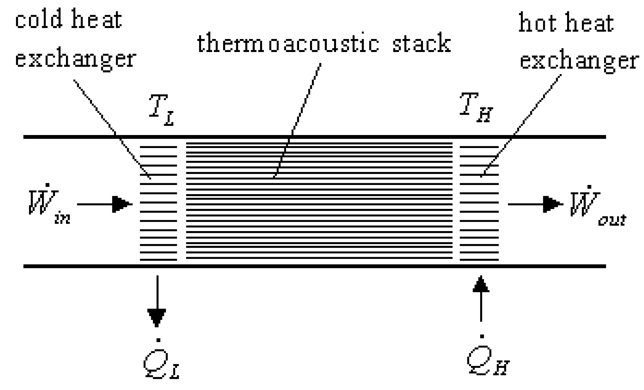
Essentially, a thermoacoustic engine consists of heat exchangers, thermoacoustic stack (or thermoacoustic regenerator) and working fluid gas. The energy flows in the apparatus is schematically illustrated in Fig.1. Heat was supplied to the engine by hot heat exchanger, and waste heat was removed by cold heat exchanger, delivering acoustic power () to the outside of system. The following assumptions are made for this model.
Fig.1.
Energy flows in a therm o acoustic engine

(i)There exist external irreversibilities due to heat transfer in the hot and the cold heat exchangers between the engine and its surrounding heat reservoirs. Because of the heat transfer, the time average temperatures (TH0 and TL0) of the working fluid are different from the reservoir temperatures (TH and TL). The second law of thermodynamics requires TH > TH0 > TL0 > TL. As a result of thermoacoustic oscillating, the temperatures (THc and TLc) of the working fluid can be expressed as complexes:
where T1 and T2 are the first-order acoustic quantities, , is the oscillating angular frequency. Here the reservoir temperatures (TH and TL) are assumed as real constants, so they have no imaginary part.
(ii)Consider that the heat transfer between the engine and its surroundings follow a generalized law (), Then
where is a complex heat transfer exponent, is the overall heat transfer coefficient and F1 is the heat transfer surface area of the hot heat exchanger, is the overall heat transfer coefficient and F2 is the heat transfer surface area of the cold heat exchanger. and have negative values if . Here the imaginary part n2 of n indicates the relaxation of a heat transfer process. Equations (3) and (4) can be rewritten as
where and are the time average of and , respectively.
The heat-transfer surface areas (F1 and F2) of the hot and cold heat exchangers are finite. The total heat transfer surface area (F) of the two heat exchangers is assumed to be a constant
(iii)There exists a rate of heat leakage () from the heat source to the heat sink [14]. It is assumed as a constant [10]. Thus
where is rate of heat transfer supplied by the heat source and is rate of heat transfer released to the heat sink.
(iv)In addition to heat resistance between the working substance and the heat reservoirs, heat leakage between the heat reservoirs, there are internal irreversibilities in the system due to miscellaneous factors such as friction and non-equilibrium activities inside the engine. The power output produced by the irreversible thermoacoustic engine is less than that of the endoreversible thermoacoustic engine with the same heat input. In other words, the rate of heat flow () from the cold working fluid to the heat sink for the irreversible thermoacoustic engine is larger than that for the endoreversible thermoacoustic engine (). The factor of internal irreversible degree to characterize the additional internal miscellaneous irreversibility effect is defined as follows
Optimal characteristics
For an endoreversible thermoacoustic engine, the second law of thermodynamics requires that
Combining equations (10) and (11) yields
The first law of thermodynamics gives that the power output of the engine is
The efficiency of the engine is
We define the heat transfer surface area ratio and working fluid temperature ratio as follows
From equations (5)-(9) and (12)-(16), we obtain the complex power output () and the complex efficiency () of the engine
The real part of the power output of the engine is
with , . Here and indicate the real part and imaginary part of complex number. The real part of the efficiency of the engine is
with , .
Eqs. (19) and (20) indicate that both power output P and efficiency of the engine are functions of the heat transfer surface area ratio (f) for given TH, TL, , , n1, n2, , and x. Taking the derivatives of and with respect to f and setting them equal zero ( and ), we can find that when f satisfies the following equation
both power output and efficiency approach optimal values
with
The parameter equation defined by equations (22) and (23) gives the fundamental relation between the optimal power output and efficiency for given TH, TL, , , n1, n2, , , and F. It is the main result of this paper.
Discussion
1. Effect of Complex Heat Transfer Exponent
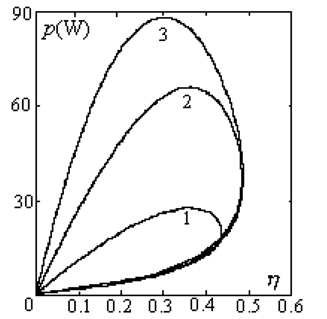
From equations (22) and (23), the optimal power output versus efficiency characteristics are dependent on heat transfer exponent for given . When the imaginary part is fixed, versus curves with are shown in figure 2. There exit an efficiency corresponding to the maximum power output and a power output corresponding to the maximum efficiency . When the real part is fixed, versus curves with and are shown in figure 3. The power output P decreases and the efficiency increases along with increasing of the .
Fig.2.
Power output p values efficiency characteristics η for 1. n1 = 1. αF = 1 and 2. n1 = −1, αF = 6 × 10⁵ and 3. n1 = 4, αF = 5 × 10⁻⁹
Fig.2.
Power output p values efficiency characteristics η for 1. n1 = 1. αF = 1 and 2. n1 = −1, αF = 6 × 10⁵ and 3. n1 = 4, αF = 5 × 10⁻⁹

2. Optimization zone
The P versus characteristics of irreversible thermoacoustic heat engine is a loop-shaped curve, as shown by figure 2 and figure 3. For all n1, when and when .
The optimization criteria of the thermoacoustic heat engine can been obtained from parameters and P0, as follows:
Fig.3.
Power output p values efficiency characteristics η for 1. n2 = 0.05, 2. n2 = 0.1 and 3. n2 = 0.15
Fig.3.
Power output p values efficiency characteristics η for 1. n2 = 0.05, 2. n2 = 0.1 and 3. n2 = 0.15
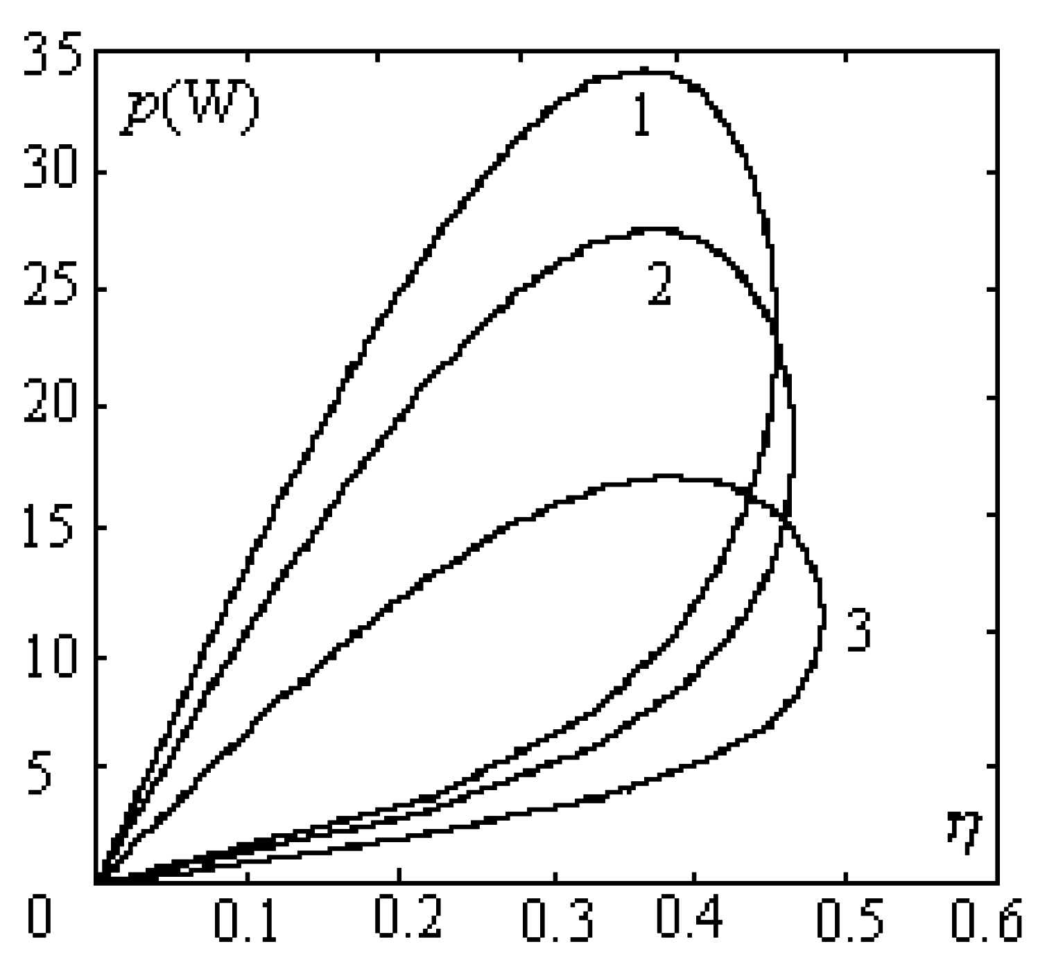
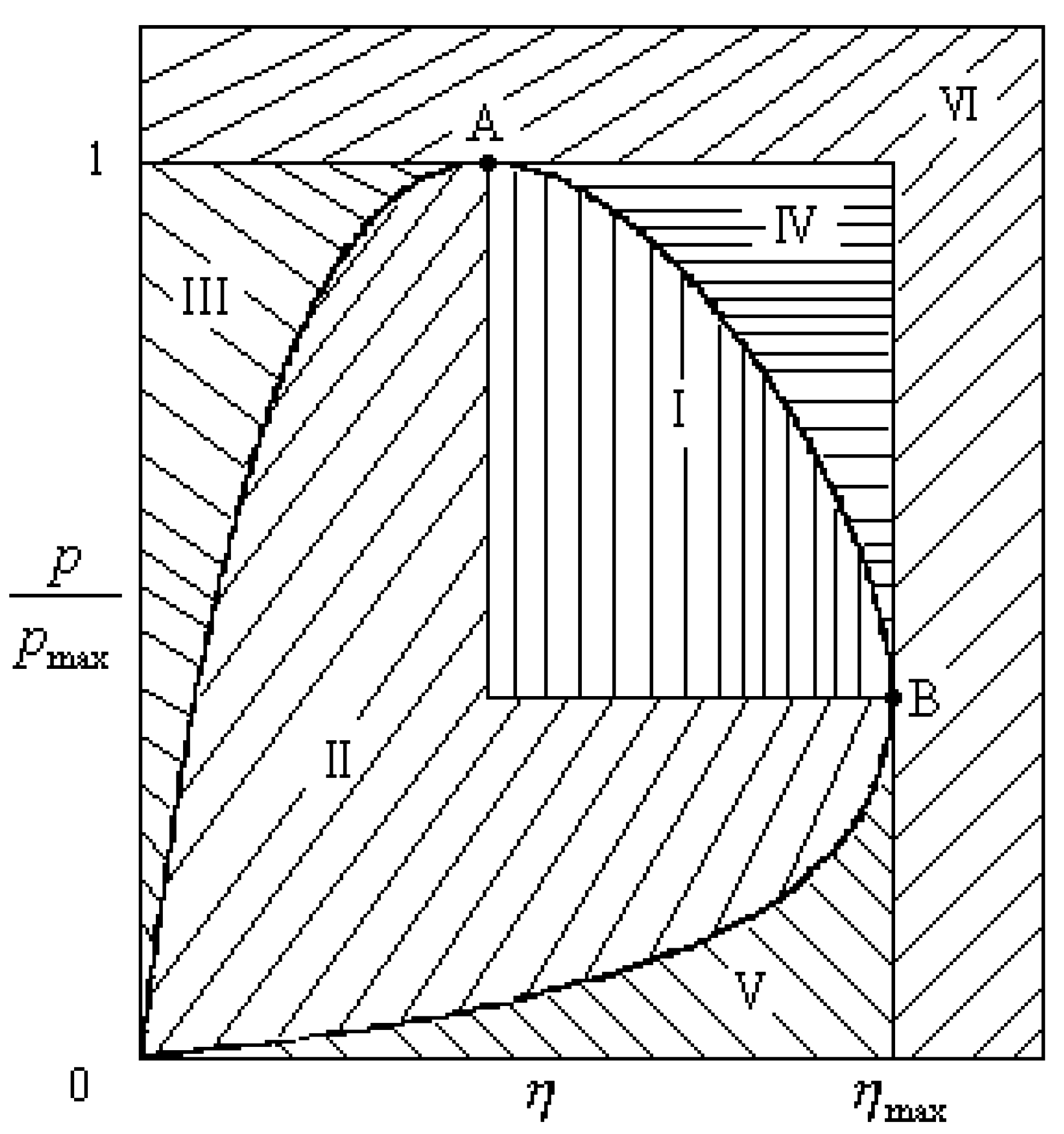
Figure 4 gives the operation zones of the thermoacoustic heat engine for special case n1 = 1 and n2=0.1. Both cases n1 = -1 and n1 = 4 are similar to case n1 = 1 in the respect of the optimal zone. The curve OABO in Fig.4 is the optimal region of the theoretical analysis given by equations (22) and (23). It is of practical signification to apply the theoretical results in this paper to the performance optimization and evaluation for the thermoacoustic heat engine. The performance as a whole for a practical thermoacoustic heat engine is the best when operation point lays on curve AB and is better when it lays in the zone Ⅰand is worse when it lays in the zone Ⅱ in figure 4. The zones Ⅲ, Ⅳ,Ⅴ are unstable regions because them is outside curve OABO and the zone Ⅵ don't exist because or in the zone.
Fig.4.
Optimal operation zones the thermoacoustic heat engine for speical case n1 = 1 and n2 = 0.1

Conclusion
For a thermoacoustic heat engine with temperature oscillating, an ordinary convective heat transfer model is incapable of predicting its thermal relaxation effect. The heat transfer exponent mast be complex number due to the thermal relaxation in heat transfer process. In summary, both the real part and the imaginary part of the heat transfer exponent change the power versus efficiency relationship quantitatively. The analysis includes the optimal performance characteristics and the optimal operation zone of the thermoacoustic heat engine with complex heat transfer exponent. The results are helpful for the selection of the optimal mode of operation of the thermoacoustic heat engine.
Acknowledgements
This material is based upon work supported by the Science Fund of Hubei Provincial Department of Education in China under the contract No. 2002A20013.
References
- Swift, G.W. Thermoacoustic engines. J. Acoust. Soc. Am. 1988, 84, 1145. [Google Scholar] [CrossRef]
- Ceperley, P.H. Gain and efficiency of a traveling wave heat engine. J. Acoust. Soc. Am. 1982, 77, 1239–1243. [Google Scholar] [CrossRef]
- Backhaus, S.; Swift, G.W. A thermoacoustic stirling heat engine. Nature 1999, 399, 335–338. [Google Scholar] [CrossRef]
- Yazaki, T.; Iwata, A.; mackawa, T.; Tominaga, A. Traveling wave thermoacoustic engine in a looped tube. Physical Review Letter 1998, 81, 3128–3131. [Google Scholar] [CrossRef]
- Novikov, I.I. The Efficiency of Atomic Power Stations. J. Nucl. Energy II 1958, 125–128. [Google Scholar]; Translated From Atomnaya Energiya 3 1957, 3, 409..
- Chambadal, P. Les Centrales Nucleaires; Armand Colin: Paris, 1957; pp. 41–58. [Google Scholar]
- Curzon, F.L.; Ahlborn, B. Efficiency of Carnot Engine at Maximum Power Output. Am. J. Phys. 1975, 43, 22–24. [Google Scholar] [CrossRef]
- Gordon, J.M. Observations on efficiency of heat engines operating at maximum power. Am. J. Phys. 1990, 58, 370–375. [Google Scholar] [CrossRef]
- Wu, C.; Chen, L.; Sun, F. Effect of the heat transfer law engines. Int. J. Energy. 1996, 21, 1127–1134. [Google Scholar] [CrossRef]
- Chen, L.; Sun, F.; Wu, C. Effect of heat transfer law on the performance of a generalized irreversible Carnot engine. J. Phys. D: Appl. Phys. 1999, 32, 99–105. [Google Scholar] [CrossRef]
- Wu, F.; Chen, L.; Wu, C.; Guo, F. Optimization zone on the performance of a generalized irreversible magnetic Stirling cryocooler. Open System & Information Dynamics 2001, 8, 291–301. [Google Scholar]
- Backhaus, S.; Swif, G.W. A thermoacoustic Stirling heat engine. Nature 1999, 399, 335–338. [Google Scholar] [CrossRef]
- Kornhauser, A.A.; Smith, J.L. Application of a complex Nusselt number to heat transfer during compression and expansion. J. Heat Transfer 1994, 116, 536–542. [Google Scholar] [CrossRef]
- Zhang, X. Ph.D. Thesis. Investigation on modeling and optimization of thermoacoustic engine systems, Huazhong University of Science and Technology, Chinese Wuhan, 2001. [Google Scholar]
© 2003 by MDPI (http://www.mdpi.org). Reproduction for noncommercial purposes permitted.
Share and Cite
MDPI and ACS Style
Wu, F.; Wu, C.; Guo, F.; Li, Q.; Chen, L. Optimization of a Thermoacoustic Engine with a Complex Heat Transfer Exponent. Entropy 2003, 5, 444-451. https://doi.org/10.3390/e5050444
AMA Style
Wu F, Wu C, Guo F, Li Q, Chen L. Optimization of a Thermoacoustic Engine with a Complex Heat Transfer Exponent. Entropy. 2003; 5(5):444-451. https://doi.org/10.3390/e5050444
Chicago/Turabian StyleWu, Feng, Chih Wu, Fangzhong Guo, Qing Li, and Lingen Chen. 2003. "Optimization of a Thermoacoustic Engine with a Complex Heat Transfer Exponent" Entropy 5, no. 5: 444-451. https://doi.org/10.3390/e5050444