Second law analysis of laminar flow in a channel filled with saturated porous media: a numerical solution

1
Mechanical Engineering Department, Persian Gulf University, Bushehr, Iran
2
Fix Equipment Lead Engineer, Namavaran Delvar Engng. & Construction Company, Tehran, Iran
*
Author to whom correspondence should be addressed.
Entropy 2005, 7(4), 300-307; https://doi.org/10.3390/e7040300
Submission received: 2 November 2005
/
Accepted: 8 December 2005
/
Published: 9 December 2005
Abstract
:This paper investigates entropy generation due to forced convection in a porous medium sandwiched between two parallel plates one of them being subjected to a uniform heat flux and the other one insulated. Our results showed that viscous dissipation will affect the entropy generation rate at the centerline of the channel since viscous dissipation is a quadratic function of velocity [1,2,3]. Neglecting the Darcy dissipation term in comparison with the terms added by Al-Hadrami et al. [4], will lead to the misunderstanding that fluid friction has no effect on the entropy generation rate at the tube centerline where the velocity derivative vanishes due to symmetry. Though the term added by [4] is O(Da) compared to the Darcy term one should not drop it unless the clear flow solution is sought [5,6,7]. Moreover, as stated by Nield [1], one should not use just the term involving velocity derivatives, as some authors have done in the past, for example [8,9,10,11]. Though in this paper the viscous dissipation effects in the energy equation are neglected, we have take them into account when it came to the entropy generation analysis.
Problem statement
Figure 1 shows the problem under consideration. When the flow in hydrodynamically fully developed one knows that the Brinkman flow model leads to the following momentum equation
with the porous medium shape factor s being defined as S = a/K1/2 wherein K is the permeability and a is the channel width.
Defining, , the thermal energy equation in the absence of flow work, viscous dissipation, thermal dispersion and axial conduction effect is
where is the normalized velocity (local velocity divided by the average velocity, i.e. = u/U), the Péclet number is , k is the effective thermal conductivity, ρ is the fluid density, cp is the specific at constant pressure, and q″ is the wall heat flux. The dimensionless coordinates are and the thermal boundary conditions are θ = 0 when x = 0, at the bottom wall and at the top wall.
Another alternative is to apply the following separation procedure
The above will lead to two ordinary differential equations that one of them needs numerical integration to be solved while the other one leads to a simple exponential answer.
Numerical details
A numerical solution is presented for the momentum and the thermal energy equation, i.e. Eqns. (1-2) subjected to the aforementioned boundary conditions. To achieve this goal, we applied an implicit finite difference scheme, backward in x and central in y. Details of the method may be found in [12] and so we neglect repeating them. Length to height ratio of the channel is set at 10. A 0.05x0.005 grid system is applied and it is observed that moving from this grid to a more intense one- being 0.001x0.0001- will change the results within less than 1%. Changing the thermal boundary condition to a constant heat flux wall, we validated our work by defining a Nusselt number Nu=ha/(2k). It is observed that our predicted Nu differs from that of [3] in the fourth figure. One may recover the known analytical data for this case as reported by [3]; however, the details and exact figures are not presented in this report for the sake of brevity.
We present a first law of thermodynamics approach to verify our solution. Considering a slice of the channel with the dimensions a.dx and applying the first law of thermodynamics, one obtains
where in U and Tm are mean velocity and bulk temperature. Rearranging the above equation in terms of non-dimensional parameters one finds
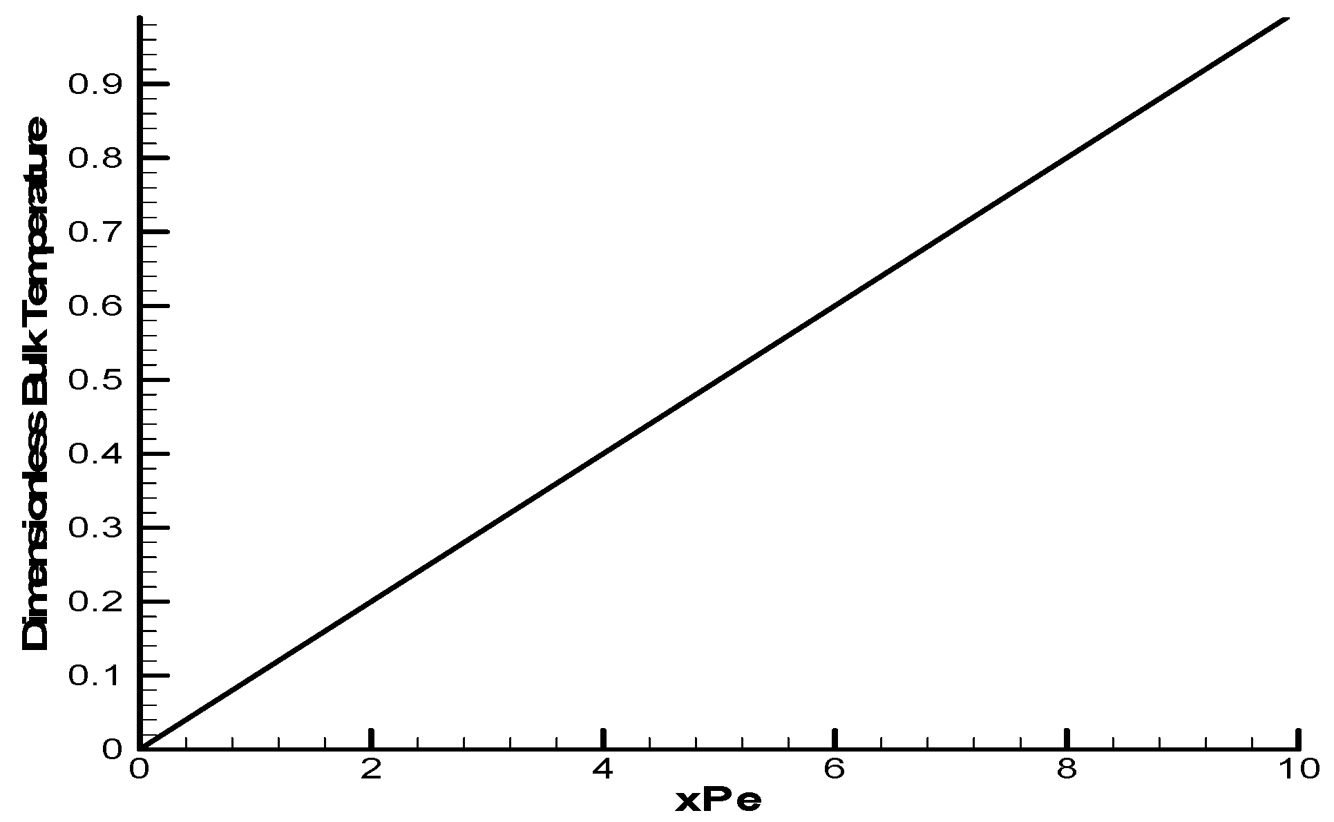
Since a uniform temperature is applied at the channel inlet, the solution to Eq. (5) reads
Our work resulted in Fig. 2. This figure may also be used for validation purpose.
Results and discussion
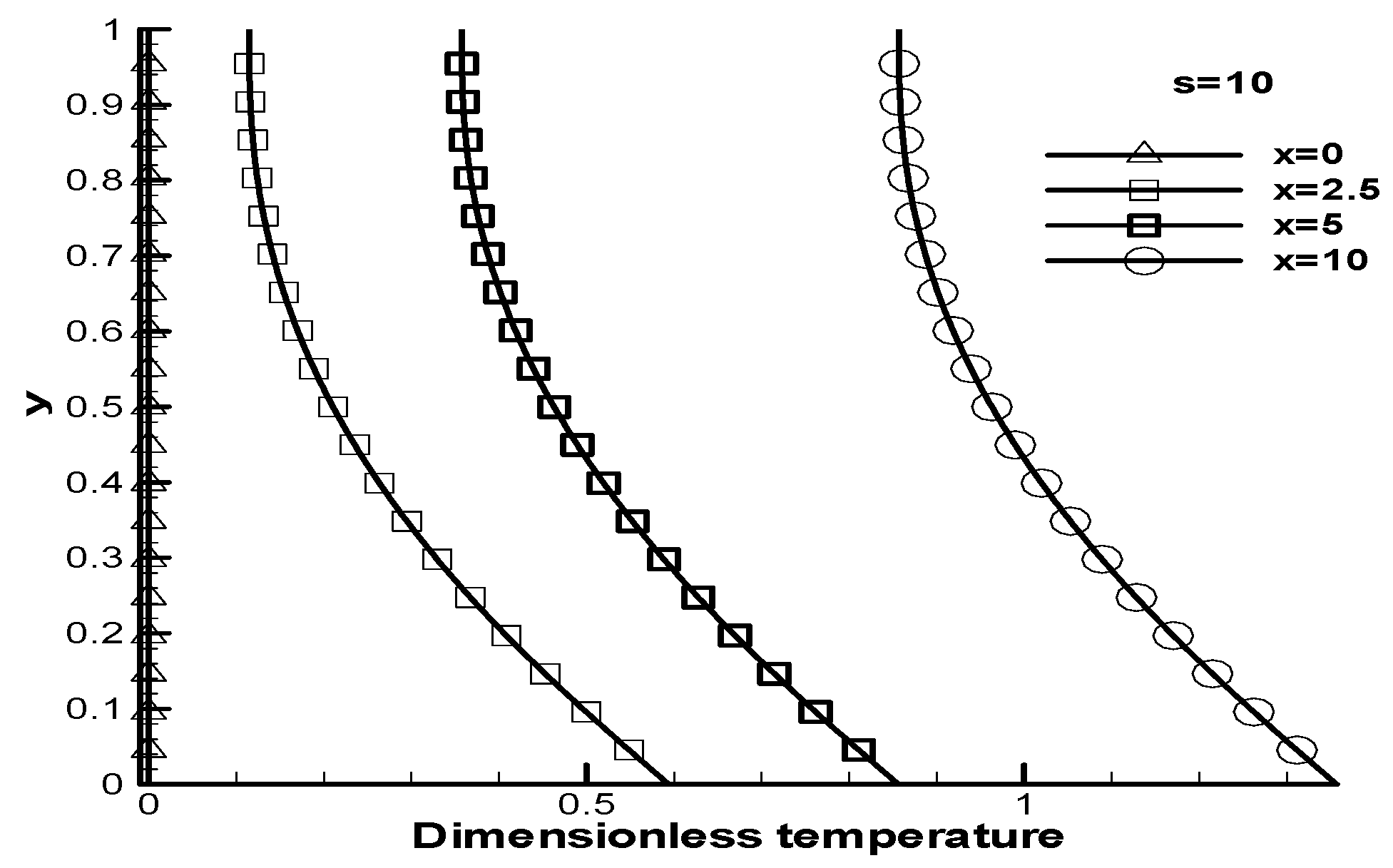
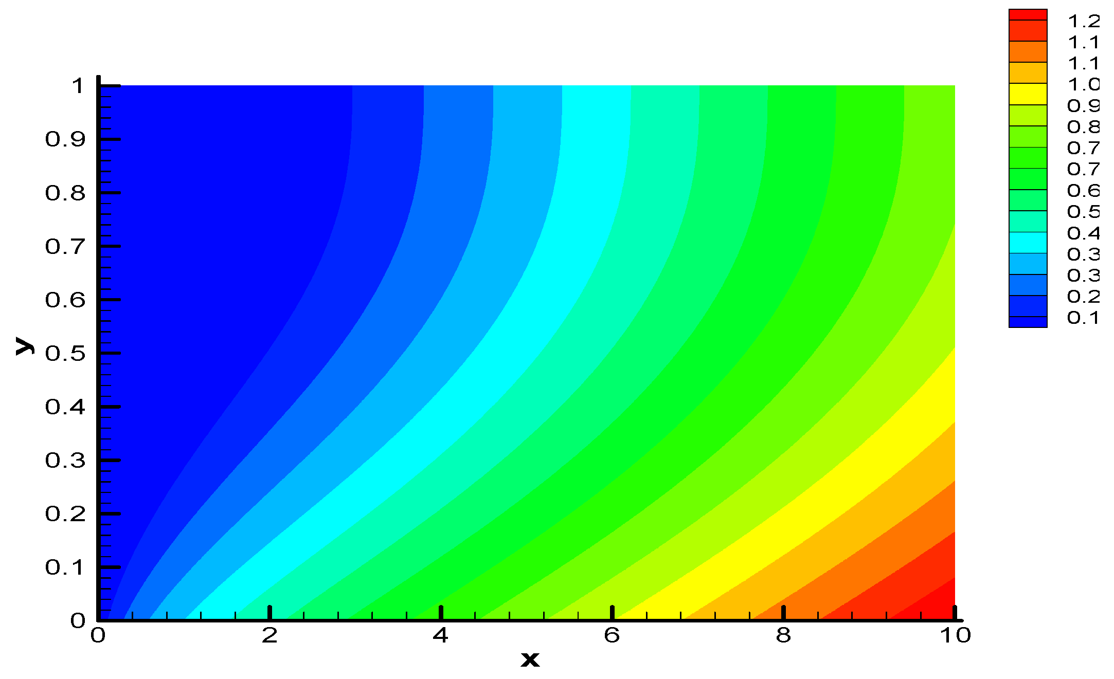
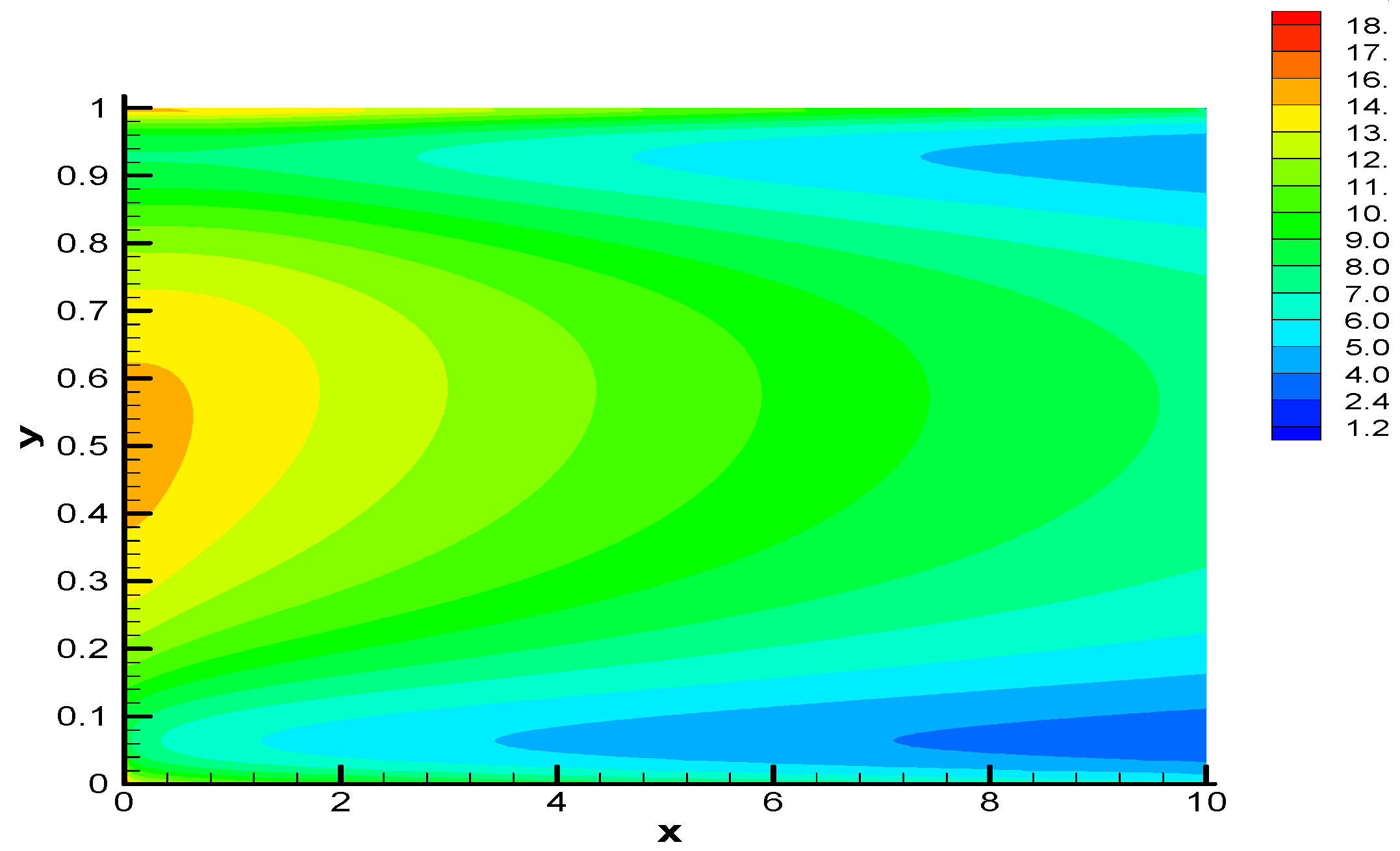
Dimensionless temperature distribution is illustrated in Fig. 3, Fig. 4 and Fig. 5. Showing the results, xPe is called x for short. Figure 3 and Figure 4 are designed to illustrate the dimensionless temperature profiles in the duct cross-section for some streamwise locations. The slopes at upper and bottom walls show that the former is adiabatic while the latter is at a constant heat flux in such a way that moving toward the upper wall both the transverse temperature gradient and the temperature itself decrease. Figure 5 shows the dimensionless temperature contours through the channel. Moving downstream, the isotherm values increase as fluid becomes heated near the bottom wall.
Figure 6, Figure 7, Figure 8, Figure 9 and Figure 10 illustrate the dimensionless entropy generation rate, Ns, for some values of s and Br while in all figures the values of Pe and Ω are fixed to 10 and 1, respectively. As a common trend in all figures one comprehends that the entropy generation rate decreases from the channel inlet to the outlet due to a fall in temperature gradients and this plunge is associated with a decrease in the heat transfer irreversibility term. As seen, for small values of s the plots of Ns experience a minimum while for large values of s one observes two local minima. For large values of s, the velocity changes in a thin region adjacent to the walls and this is accompanied by a steep temperature gradient near the bottom wall leading to a local maximum for Ns that happens near the bottom wall. Though near the upper wall the temperature gradients are small, Ns reaches a local maximum for a decrease in the temperature appearing in the denominator of Ns. Ns is defined here similar to Bejan [13], without the assumption that temperature difference in a cross-section is small, as
Some authors have dropped the denominators to define an entropy generation number but this definition may work out to be a representative of entropy generation rate only if , i.e. is negligible, as stated by Bejan [13] and applied by some authors [14,15,16,17]. This can be mathematically interpreted as Ω >> θ; which is not the case here.
Far from the walls, in the channel centerline regions, the velocity is distributed somehow uniformly so that the velocity gradients are small in this region. On the other hand, the velocity magnitude contributes to fluid friction irreversibility (FFI). For this reason, unlike small s cases, the entropy generation plot will not pass through one minimum in the channel centerline. Actually, when s is large Ns recovers in the channel centerline for the velocity attains its maximum in this region and this fact is much more voiced for higher values of Br. Comparing Fig. 6 with Fig. 7, one realizes that moving from Br=0.1 to Br=1 with s=10 stretches the Ns plot by a factor, say, approximately 8. The two minima for large s will happen near the walls and for small s the so-called minimum takes place at the centerline. However, the maximum entropy generation rate depends on the interaction between heat transfer and fluid friction irreversibility that, in turn, depends on Pe, s, Br, and Ω.
Acknowledgments
We are indebted to Professor D.A. Nield of the University of Auckland for his improving comments.
References
- Nield, D.A. Comments on ‘A new model for viscous dissipation in porous media across a range of permeability values’ by A. K. Al-Hadrhrami, L. Elliott and D. B. Ingham. Transport Porous Media 2004, 55, 253–254. [Google Scholar] [CrossRef]
- Bejan, A. Convection Heat Transfer. Wiley, 1984. [Google Scholar]
- Nield, D.A.; Bejan, A. Convection in Porous Media, 2nd Ed. ed; Springer-Verlag, 1999. [Google Scholar]
- Al-Hadrami, A.K.; Elliott, L.; Ingham, D.B. A new model for viscous dissipation in porous media across a range of permeability values. Transport Porous Media 2003, 53, 117–122. [Google Scholar]
- Nield, D.A. Private communications, 2005.
- Nield, D.A. Resolution of a paradox involving viscous dissipation and nonlinear drag in a porous medium. Transport Porous Media 2000, 41, 349–357. [Google Scholar] [CrossRef]
- Nield, D.A. Modelling fluid flow in saturated porous media and at interfaces. In Transport Phenomena in Porous Media II; (D.B. Ingham and I. Pop); Elsevier Science: Oxford, 2002. [Google Scholar]
- Tasnim, S.H.; Mahmud, S.; Mamun, M.A.H. Entropy generation in a porous channel with hydromagnetic effect. Exergy, Int. J. 2002, 2, 300–308. [Google Scholar]
- Mahmud, S.; Fraser, R.A. Flow, thermal, and entropy generation characteristics inside a porous channel with viscous dissipation. Int. J. Thermal Sci. 2005, 44, 21–32. [Google Scholar]
- Mahmud, S.; Fraser, R.A. Entropy-energy analysis of porous stack: steady state conjugate problem. Int. J. Exergy 2004, 1(3), 387–398. [Google Scholar]
- Mahmud, S.; Fraser, R.A. Mixed convection-radiation interaction in a vertical porous channel: entropy generation. Energy 2003, 28, 1557–1577. [Google Scholar]
- Tannehill, J.C.; Anderson, D.A.; Pletcher, R.H. Computational Fluid Mechanics and Heat Transfer, 2nd Ed. ed; Taylor & Francis, 1997. [Google Scholar]
- Bejan, A. Entropy generation through heat and fluid flow; Wiley, 1982. [Google Scholar]
- Ibanez, G.; Cuevas, S.; Lopez de Haro, M. Heat transfer in asymmetric convective cooling and optimized entropy generation rate. Rev. Mex. Fis. 2003, 49(4), 338–343. [Google Scholar]
- Hooman, K. Fully Developed Temperature Distribution in a Porous Saturated Duct of Elliptical Cross-Section, with Viscous Dissipation Effects and Entropy Generation Analysis. Heat Transfer Research 2005, 36(3), 237–245. [Google Scholar] [CrossRef]
- Hooman, K. Second Law Analysis of Thermally Developing Forced Convection in a Porous Medium. Heat Transfer Research 2005, 36(6), 437–447. [Google Scholar] [CrossRef]
- Hooman, K. Analysis of entropy generation in porous media imbedded inside elliptical passages. Int. J. Heat Tech. 2005, 23(1). to appear. [Google Scholar]
Figure 1.
Definition sketch.
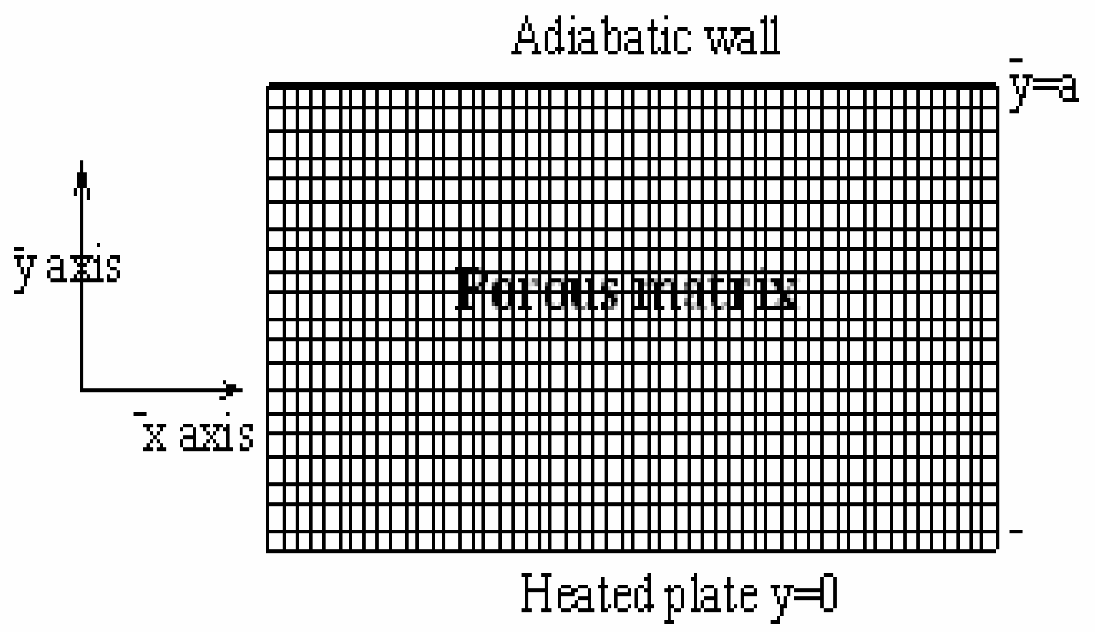
Figure 2.
Dimensionless bulk temperature for Pe=10 (numerical results).

Figure 3.
Dimensionless temperature distribution at different longitudinal locations (s=0.1)
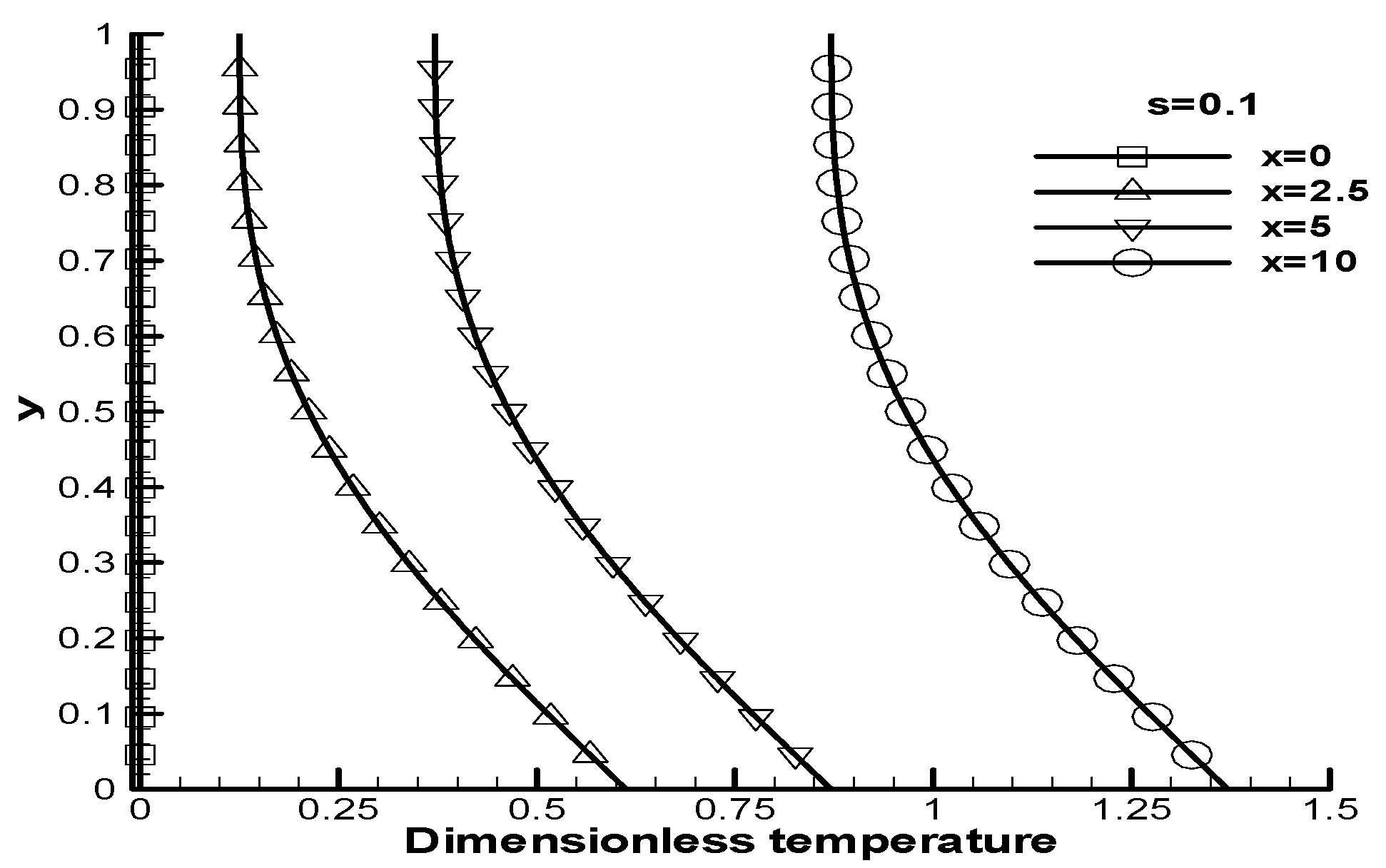
Figure 4.
Dimensionless temperature distribution at different longitudinal positions (s=10)

Figure 5.
Dimensionless temperature contours (s=0.1)

Figure 6.
Ns versus y for some longitudinal locations (s=10 and Br=1).
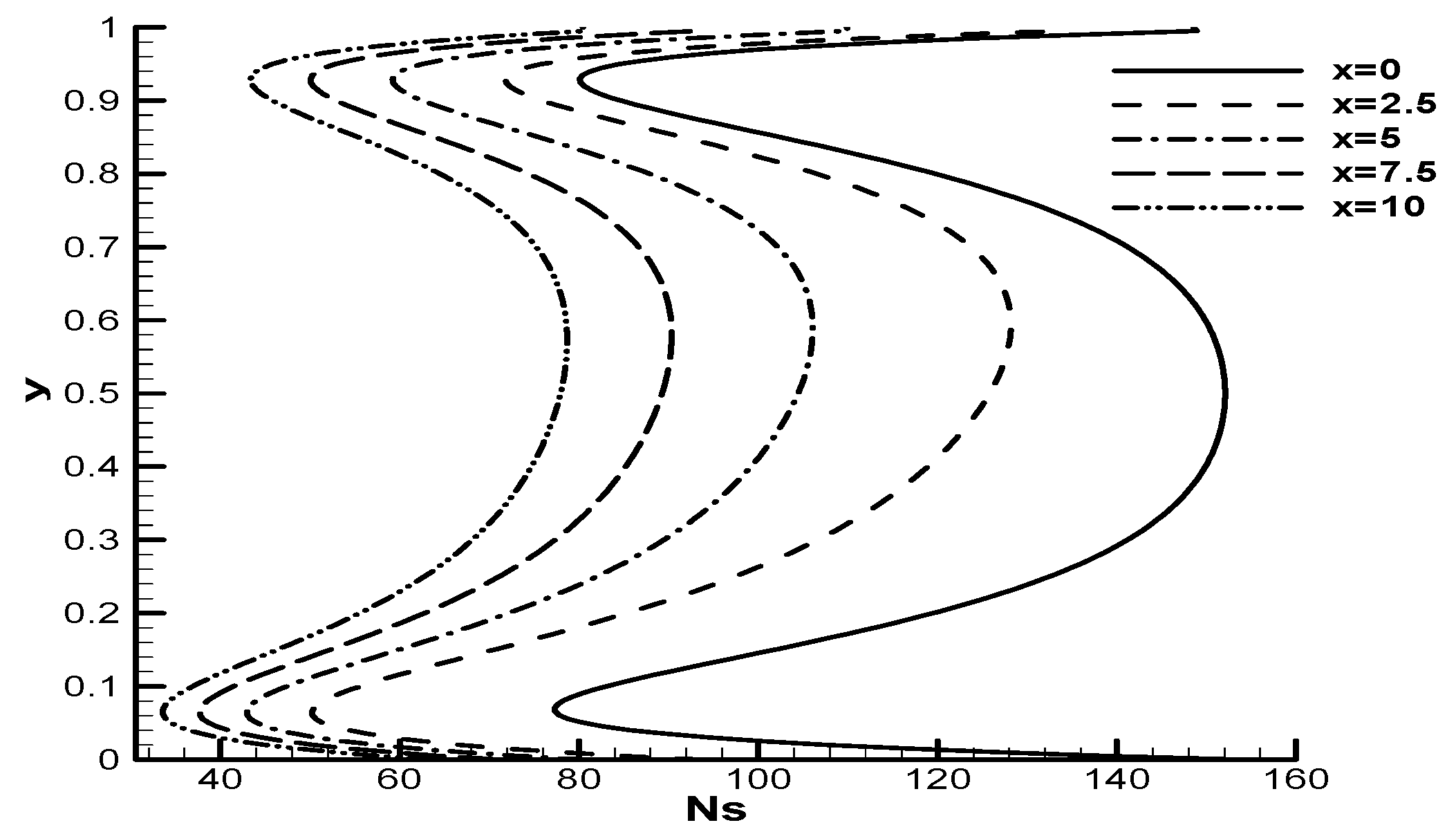
Figure 7.
Ns versus y for some longitudinal locations; s=10, Br=0.1 (legends identified on Fig. 6).
Figure 7.
Ns versus y for some longitudinal locations; s=10, Br=0.1 (legends identified on Fig. 6).
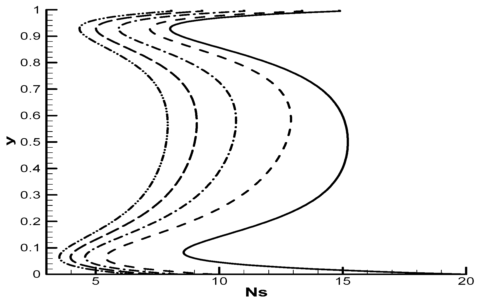
Figure 8.
Ns versus y for some longitudinal locations; s=0.1, Br=1 (legends are identified on Fig. 6).
Figure 8.
Ns versus y for some longitudinal locations; s=0.1, Br=1 (legends are identified on Fig. 6).
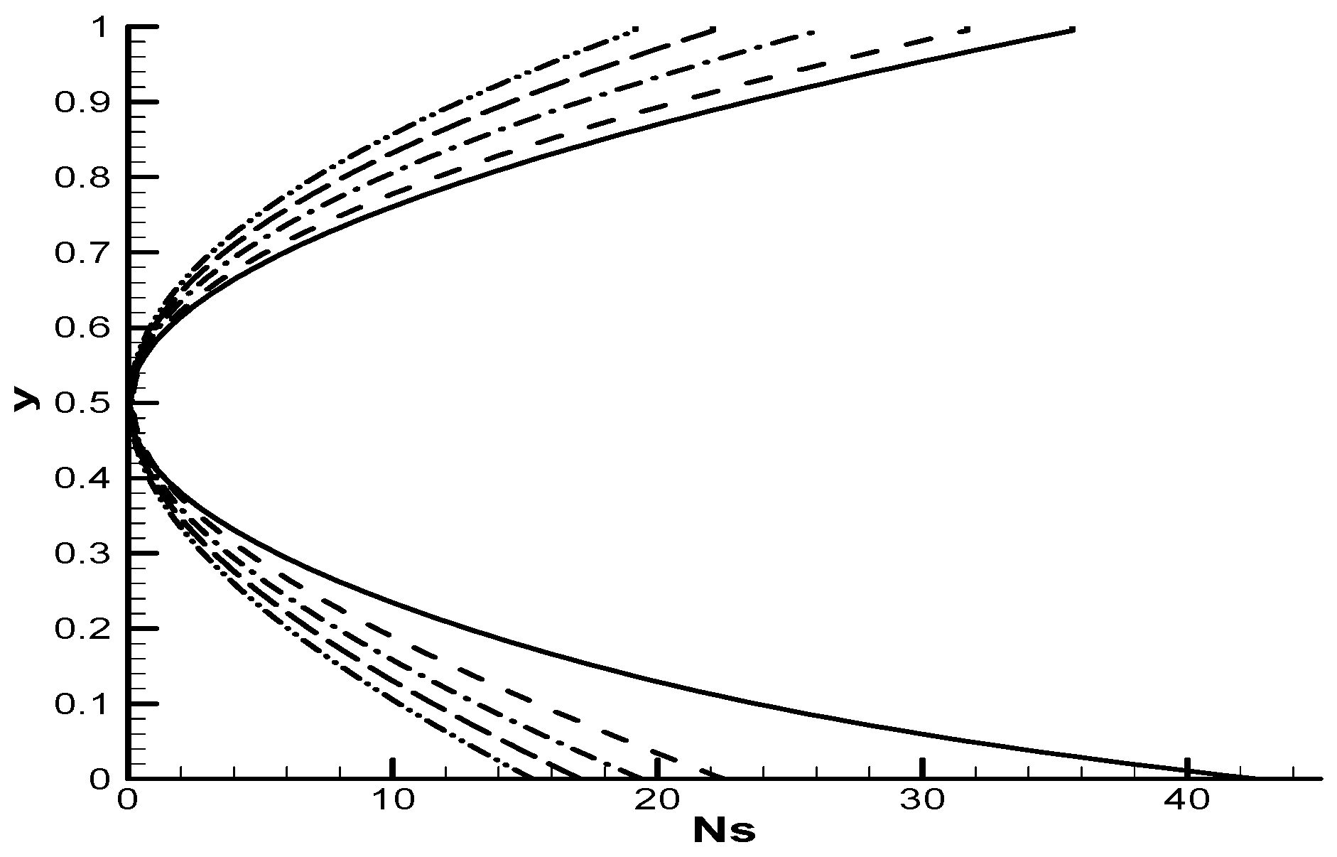
Figure 9.
Ns versus y for some x with s=0.1 and Br=0.1 (legends are identified on Fig. 6).
Figure 9.
Ns versus y for some x with s=0.1 and Br=0.1 (legends are identified on Fig. 6).
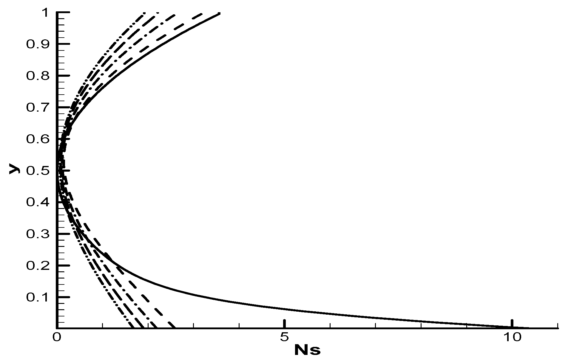
Figure 10.
Ns contours through the channel (s=10 and Br=0.1).
© 2005 by MDPI (http://www.mdpi.org). Reproduction for noncommercial purposes permitted.
Share and Cite
MDPI and ACS Style
Hooman, K.; Ejlali, A. Second law analysis of laminar flow in a channel filled with saturated porous media: a numerical solution. Entropy 2005, 7, 300-307. https://doi.org/10.3390/e7040300
AMA Style
Hooman K, Ejlali A. Second law analysis of laminar flow in a channel filled with saturated porous media: a numerical solution. Entropy. 2005; 7(4):300-307. https://doi.org/10.3390/e7040300
Chicago/Turabian StyleHooman, Kamel, and Arash Ejlali. 2005. "Second law analysis of laminar flow in a channel filled with saturated porous media: a numerical solution" Entropy 7, no. 4: 300-307. https://doi.org/10.3390/e7040300