Innovative Target for Production of Technetium-99m by Biomedical Cyclotron

 , , , and
Abstract
:
1. Introduction
2. State-of-the-Art: Cyclotron Target for 99mTc Production
3. Materials and Methods
3.1. Materials
3.2. Cyclotron
3.3. Unique Vacuum System for Target Preparation
3.4. Magnetron Sputtering
3.5. Thin Film Analysis
3.6. Vacuum Brazing
3.7. Dissolution Test and Gamma-Spectroscopy
4. Results and Discussion
4.1. Optimization of Magnetron Sputtering Parameters
4.2. Irradiation
4.3. Dissolution Test and Chemical Inertness Prove
4.4. Magnetron Sputtering Efficiency and Further Perspectives
5. Conclusions
6. Patents
Author Contributions
Funding
Acknowledgments
Conflicts of Interest
References
- Boschi, A.; Martini, P.; Pasquali, M.; Uccelli, L. Recent achievements in Tc–99m radiopharmaceutical direct production by medical cyclotrons. Drug Dev. Ind. Pharm. 2017, 43, 1402–1412. [Google Scholar] [CrossRef] [PubMed]
- Esposito, J.; Vecchi, G.; Pupillo, G.; Taibi, A.; Uccelli, L.; Boschi, A.; Gambaccini, M. Evaluation of and Productions Based on a High–Performance Cyclotron. Sci. Technol. Nucl. Ins. 2013, 2013, 14. [Google Scholar] [CrossRef]
- Martini, P.; Boschi, A.; Cicoria, G.; Zagni, F.; Corazza, A.; Uccelli, L.; Pasquali, M.; Pupillo, G.; Marengo, M.; Loriggiola, M.; et al. In–house cyclotron production of high–purity Tc–99m and Tc–99m radiopharmaceuticals. Appl. Radiat. Isot. Appl. Radiat. Isot. 2018, 139, 325–331. [Google Scholar] [CrossRef] [PubMed]
- Accelerator–based Alternatives to Non–HEU production of 99Mo/99mTc. In Proceedings of the 3rd Research Coordination Meeting of IAEA, Vienna, Austria, 22–26 June 2015.
- IAEA Cyclotron Based Production of Technetium-99m; IAEA: Vienna, Austria, 2017; ISBN 978-92-0-102916-4.
- Bénard, F.; Buckley, K.R.; Ruth, T.J.; Zeisler, S.K.; Klug, J.; Hanemaayer, V.; Vuckovic, M.; Hou, X.; Celler, A.; Appiah, J.P.; et al. Implementation of Multi–Curie Production of (99m)Tc by Conventional Medical Cyclotrons. J. Nucl. Med. 2014, 55, 1017–1022. [Google Scholar] [CrossRef] [PubMed]
- European Pharmacopoeia 9.3. In Sodium Pertechnetate (99mTc) Injection (Accelerator produced) Monograph No. 2891, January 2018: 2891 ed; World Health Organization: Geneva, Switzerland, 2018; Volume 9.3, pp. 4801–4803.
- Celler, A.; Hou, X.; Bénard, F.; Ruth, T. Theoretical modeling of yields for proton–induced reactions on natural and enriched molybdenum targets. Phys. Med. Biol. 2011, 56, 5469. [Google Scholar] [CrossRef] [PubMed]
- Schaffer, P.; Bénard, F.; Bernstein, A.; Buckley, K.; Celler, A.; Cockburn, N.; Corsaut, J.; Dodd, M.; Economou, C.; Eriksson, T. Direct Production of 99m Tc via 100 Mo (p, 2n) on Small Medical Cyclotrons. Phys. Procedia. 2015, 66, 383–395. [Google Scholar] [CrossRef]
- Martini, P.; Boschi, A.; Cicoria, G.; Uccelli, L.; Pasquali, M.; Duatti, A.; Pupillo, G.; Marengo, M.; Loriggiola, M.; Esposito, J. A solvent–extraction module for cyclotron production of high–purity technetium–99m. Appl. Radiat. Isot. Appl. Radiat. Isot. 2016, 118, 302–307. [Google Scholar] [CrossRef] [PubMed]
- Nishikata, K.; Kimura, A.; Ishida, T.; Kitagishi, S.; Tsuchiya, K.; Akiyama, H.; Nagakura, M.; Suzuki, K. Method of Producing Radioactive Molybdenum. U.S. Patent 13/675,769, 30 May 2013. [Google Scholar]
- Avetisyan, A.; Dallakyan, R.; Sargsyan, R.; Melkonyan, A.; Mkrtchyan, M.; Harutyunyan, G.; Dobrovolsky, N. The powdered molybdenum target preparation technology for 99mTc production on C18 cyclotron. IJEIT 2015, 4, 37–44. [Google Scholar]
- Barbosa, L.A.M.M. System and Method for Producing Radiomedical-Grade Tc-99m. WIOP Patent WO/2014/130384, 28 August 2014. [Google Scholar]
- Gagnon, K.; Wilson, J.S.; Holt, C.M.B.; Abrams, D.N.; McEwan, A.J.B.; Mitlin, D.; McQuarrie, S.A. Cyclotron production of 99mTc: Recycling of enriched 100Mo metal targets. Appl. Radiat. Isot. 2012, 70, 1685–1690. [Google Scholar] [CrossRef]
- Gagnon, K.; McQuarrie, S.; Wilson, J. Production of Technetium from a Molybdenum Metal Target. WIOP Patent WO 2012139220 A1, 18 December 2012. [Google Scholar]
- Wilson, J.; Gagnon, K.; McQuarrie, S. Production of Technetium from a Molybdenum Metal Target. U.S. Patent US20140029710A1, 30 January 2014. [Google Scholar]
- Zeisler, S.K.; Hanemaayer, V.; Buckley, K.R. Target System for Irradiation of Molybdenum with Particle Beams. WIOP Patent WO2015161385 A1, 29 October 2015. [Google Scholar]
- Manenti, S.; Holzwarth, U.; Loriggiola, M.; Gini, L.; Esposito, J.; Groppi, F.; Simonelli, F. The Excitation Functions of 100 Mo (p, x) 99-Mo and 100-Mo (p, 2n) 99m-Tc. Appl. Radiat. Isot. 2014, 94, 344–348. [Google Scholar] [CrossRef]
- Zyuzin, A.; Guérin, B.; van Lier, E.; Tremblay, S.; Rodrigue, S.; Rousseau, J.A.; Dumulon–Perreault, V.; Lecomte, R.; van Lier, J.E. Cyclotron Production of 99m-Tc. In Proceedings of the WTTC13, Roskilde, Denmark, 26–28 July 2010. [Google Scholar]
- Fink, C.G. Electroplating and Process of Producing Same. U.S. Patent US1885700A, 1 November 1932. [Google Scholar]
- Morley, T.J.; Penner, L.; Schaffer, P.; Ruth, T.J.; Bénard, F.; Asselin, E. The Deposition of Smooth Metallic Molybdenum from Aqueous Electrolytes Containing Molybdate Ions. Electrochem. Comm. 2012, 15, 78–80. [Google Scholar] [CrossRef]
- Kazimierczak, H.; Ozga, P.; Socha, R.P. Investigation of electrochemical co–deposition of zinc and molybdenum from citrate solutions. Electr. Acta 2013, 104, 378–390. [Google Scholar] [CrossRef]
- Kipouros, G.J.; Sadoway, D.R. The electrodeposition of improved molybdenum coatings from molten salts by the use of electrolyte additives. J. Appl. Electrochem. 1988, 18, 823–830. [Google Scholar] [CrossRef]
- Ene, N.; Donath, C. Texture of electrolytic Mo deposition from molten alkali halide. J. Optoelectron. Adv. M. 2006, 8, 708. [Google Scholar]
- Schaffer, P.; Benard, F.; Buckley, K.R.; Hanemaayer, V.; Manuela, C.H.; Klug, J.A.; Kovacs, M.S.; Morley, T.J.; Ruth, T.J.; Valliant, J. Processes, systems, and apparatus for cyclotron production of technetium–99m. U.S. Patent US 2013/0301769 A1, 14 November 2013. [Google Scholar]
- Jalilian, A.R.; Targholizadeh, H.; Raisali, G.R.; Zandi, H.; Dehgan, M.K. Direct Technetium radiopharmaceuticals production using a 30MeV Cyclotron. Daru 2011, 19, 187–192. [Google Scholar] [PubMed]
- Folger, H.; Klemm, J.; Muller, M. Preparation of Nuclear Accelerator Targets by Focused Ion Beam Sputter Deposition. IEEE Trans. Nucl. Sci. 1983, 30, 1568–1572. [Google Scholar] [CrossRef] [Green Version]
- Morrall, P.S. The target preparation laboratory at daresbury. In Nuclear Instruments and Methods in Physics Research Section A: Accelerators, Spectrometers, Detectors and Associated Equipment; Elsevier: Amsterdam, The Netherlands, 2008; Volume 590, pp. 118–121. [Google Scholar]
- Maier, H.J.; Friebel, H.U.; Frischke, D.; Grossmann, R. State of the art of high vacuum sputter deposition of nuclear accelerator targets. In Nuclear Instruments and Methods in Physics Research Section A: Accelerators, Spectrometers, Detectors and Associated Equipment; Elsevier: Amsterdam, The Netherlands, 1993; Volume 334, pp. 137–141. [Google Scholar]
- Johnson, R.R.; Gelbart, W.Z.; Abeysekera, B.; Matei, L.; McRae, G. Target, Apparatus and Process for the Manufacture of Molybdenum–100 Targets. WIOP Patents WO2016023113A1, 18 February 2016. [Google Scholar]
- Stolarz, A.; Kowalska, J.A.; Jasiński, P.; Janiak, T.; Samorajczyk, J. Molybdenum targets produced by mechanical reshaping. J. Radioanal. Nucl. Chem. 2015, 305, 947–952. [Google Scholar] [CrossRef] [PubMed] [Green Version]
- Cicoria, G.; Pancaldi, D.; Piancastelli, L.; Giovaniello, G.; Bianconi, D.; Bollini, D.; Menapace, E.; Givollani, S.; Pettinato, C.; Spinelli, A.; et al. Development and operational test of a solid target for the PETtrace cyclotron. In Proceedings of the 13th European Symposium on Radiopharmacy and Radiopharamceuticals, Lucca, Italy, 30 March 30–2 April 2006; pp. 3–4. [Google Scholar]
- Detor, A.J.; Hodge, A.M.; Chason, E.; Wang, Y.; Xu, H.; Conyers, M.; Nikroo, A.; Hamza, A. Stress and microstructure evolution in thick sputtered films. Acta Mater. 2009, 57, 2055–2065. [Google Scholar] [CrossRef]
- Vink, T.J.; Somers, M.A.J.; Daams, J.L.C.; Dirks, A.G. Stress, strain, and microstructure of sputter-deposited Mo thin films. J. Appl. Phys. 1991, 70, 4301–4308. [Google Scholar] [CrossRef]
- Thornton, J.A. Influence of apparatus geometry and deposition conditions on the structure and topography of thick sputtered coatings. J. Vac. Sci. Technol. 1974, 11, 666–670. [Google Scholar] [CrossRef]
- Karabacak, T.; Senkevich, J.J.; Wang, G.-C.; Lu, T.-FM. Stress reduction in sputter deposited films using nanostructured compliant layers by high working–gas pressures. J. Vac. Sci. Technol. 2005, 23, 986. [Google Scholar] [CrossRef]
- Kume, M.; Carey, P.C.; Gaehle, G.; Madrid, E.; Voller, T.; Margenau, W.; Welch, M.J.; Lapi, S.E. A semi–automated system for the routine production of copper–64. Appl. Radiat. Isot. 2012, 70, 1803–1806. [Google Scholar] [CrossRef] [PubMed]
- Sun, X.; Anderson, C.J. Production and applications of copper–64 radiopharmaceuticals. In Methods in Enzymology; Academic Press: Cambridge, MA, USA, 2004; Volume 386, pp. 237–261. [Google Scholar]
- Obata, A.; Kasamatsu, S.; McCarthy, D.W.; Welch, M.J.; Saji, H.; Yonekura, Y.; Fujibayashi, Y. Production of therapeutic quantities of 64Cu using a 12 MeV cyclotron. Nucl. Med. Biol. 2003, 30, 535–539. [Google Scholar] [CrossRef]
- Lin, M.; Waligorski, G.J.; Lepera, C.G. Production of curie quantities of 68Ga with a medical cyclotron via the 68Zn(p,n)68Ga reaction. Appl. Radiat. Isot. 2018, 133, 1–3. [Google Scholar] [CrossRef] [PubMed]
- Targholizadeh, H.; Raisali, G.; Jalilian, A.R.; Rostampour, N.; Ensaf, M.; Dehghan, M.K. Cyclotron production of technetium radionuclides using a natural metallic molybdenum thick target and consequent preparation of [Tc]–BRIDA as a radio–labelled kit sample. Nukleonika 2010, 55, 113–118. [Google Scholar]
- Vopsaroiu, M.; Thwaites, M.J.; Rand, S.; Grundy, P.J.; Grady, K.O. Novel sputtering technology for grain–size control. IEEE Trans Magn. 2004, 40, 2443–2445. [Google Scholar] [CrossRef]
Sample Availability: Samples of the targets are not available from the authors. |


| Country | Institution | Cyclotron Type | Target-holder System | Irradiation Conditions | Target Material | Backing Material | Deposition Process | Problems Notes | Ref. |
|---|---|---|---|---|---|---|---|---|---|
| Saudi Arabia | KFSHand RC 1 | CS-30, 15–23 MeV | Cooled by both water and He, channels, beam at 90° to target. | 1 µA 10 min in 2013; 15 µA already burnt | natMo, oxide, 100Mo | Cu, Al | Hydraulically pressing natMo, 100Mo oxides powder into the circular cavity target plates, heating (450–400 °C) | Only the low current test was satisfactory. natMo burns. | [4,5] |
| Canada | University of Alberta | TR24 ACSI 2 500 µA, 24 MeV p+ | - | - | Mo metallic | Ta, W, glassy carbon, quartz, Al2O3 | 1600 °C sintering in reducing atmosphere, 600 °C press bonding to a backing | Not tested | [5] |
| TR19 ACSI, 19 MeV p+ | Rectangular inclined | 100 µA | Mo metallic | Al2O3 | 1600 °C sintering in reducing atmosphere, 600 °C press bonding to a backing | No information about tests | [4] | ||
| TR24 ACSI 500 µA, 24 MeV | TR24 standard, rectangular inclined | 150–500 µA | Mo metallic | Al | Foils composed of powders rolled, annealed, hot pressed to backing | The backing is not inert as claimed | [4] | ||
| TR19 ACSI, 19 MeV p+ | Rectangular inclined | 20–30 µA | Mo metallic | Al | Hydraulically pressed to backing | The backing is not inert as claimed | [14] | ||
| TR19/9 ASCI, 19 MeV p+ | 30 ° to beam | 15.5/18 MeV up to 95 µA max 71 µA average on target 360 min | Mo metallic | Al, Ag, Pt, Au, Ta, Ti, V, Ni, Zn, Zr, Nb, Ru, Rh, Pd, Ir | Foils, pressing to a backing, melting on Ta backing, 1600 °C sintering in reducing atmosphere, 400–500 °C press bonding to the backing of Ta, Cu, preliminary oxidized Al in H2O2 and HNO3 | The backing is not inert as claimed. No clear data on Al pre-oxidized. | [14,15,16] | ||
| TRIUMF | TR19 ACSI | Patented ACSI TR19 target station: both inclined to beam with microchannels and perpendicular to the beam | 80–300 µA 16–30 MeV 0.5–8 h; 10.8 kW, 0.6 kW/cm2, 300 µA 18 MeV beam spot 10 × 20 mm 10° to beam. (< 500 °C on a plate) | Mo metallic oxidation-reduction-Mo metallic refined | Ta, other transition metals are described but not claimed | Electrophoretic deposition from a mixture of refined Mo powders 10 µm + molybdate + binder onto Ta backing, sintering 1200–1900 °C 38 h in an inert atmosphere (final receipt 1700 °C 5 h) | 85% density; Ta backing is not inert as claimed | [4,5,6,25] | |
| TR24/TR30 ACSI | TR30 target | 24 MeV. 500 µA, 2.1 kW, 1.2 kW/cm2 | Mo metallic | Ta | Ta backing is not inert as claimed | [4] | |||
| GE PETtrace | GE PETtrace | 16.5 MeV 130 µA, 5.6 kW, 0.3 kW/cm2 | 100Mo metallic powders | GLIDCOP 3 30 mm D 1.3 mm thick, brazed to 20 mm 0.7 mm thick Mo | Mo sintered at 1300–2100 °C disc 18.5–19.5 mm diameter 0.6 mm thick, placed in GLIDCOP baseplate and brazed in a vacuum, H2/Ar at 500–1000 °C by Ag-Cu-P | No chemical inertness | [4,9,17] | ||
| - | - | - | Electrochemical deposition up to 20 µm Mo from aqueous solution 10M acetate | Deposition inefficient <2% | [21] | ||||
| ACSI | TR19 ACSI | Inclined | 15–52 µA 1.5–3 h 15.5–17 MeV | 100Mo powders | Ta | Direct melting onto a backing | No data on thickness and performance. Nonuniform thickness. | [19] | |
| Isopor-Isotopos Para Diagnostico E Terapeutica S.A. | Low energy cyclotron | - | - | 100Mo metallic or oxide | 3-layer sandwich: substrate 40–1500 µm/100Mo layer 25–500 µm/2nd hard core layer(Al, Ag, Cu) 25–500 µm/1st hard core layer (Nb, Pt, Ta, Ag, Havar) | Strange and unclear target concept | [30] | ||
| Japan | Fukui Medical University, Matsuoka | - | Vertical beam | - | - | Target vessel for in situ preparation (Alumina) | - | The production of 89Zr by 89Y(p,n) was investigated; not tested for Tc | [5] |
| Japan Atomic Energy Agency, Ibaraki | Nuclear reactor | - | (n,γ) reaction | MoO3 pellet | Irradiation container | Plasma sintering method + oxidation process | Low thermal conductivity material | [11] | |
| MIC NIRS 4 | - | Horizontal beam | - | 3–5 mm layered 100MoO3 | Target vessel for irradiation, dissolution | Preparation of 3–5 mm thick 100Mo oxide layer: 100Mo + H2O2 + N2 flow in a target vessel | Enriched powder; lower 99mTc yield/higher contaminants | [4] | |
| - | Vertical beam | - | Powder 100Mo as purchased, without solidification | SiC target vessel | - | Limited information | [4] | ||
| Armenia | Cyclotron C18 | Nitra commercial solid target system | - | Mo/MoO3 powder pellet + Ag powder compound | - | - | Limited information | [5,12] | |
| A. I Alikhanyan National Science Laboratory | Cyclotron C18 | Target is fixed by pneumatic clamps; (work in progress--> cryogenic cooling to use 100 µA) | 18 MeV; proton current 30 µA | Tablet of −natMo | Solid state target disk: Nb or Ti | Compression method and tablet surface burning method using a focused laser beam to increase mechanical strength and additional treatment to provide adhesion with the backing | No irradiation test | [4] | |
| India | VECC 5 | Low power cyclotron | Circular target | 8–18 MeV, 10–50 nA, 5 min | natMo foils 25 µm | Cu spacers | A stack of 4–7 25 µm foils with Cu foil monitor | Very low currents | [4,5] |
| 1–6 h, 1–3 µA, 8–18 MeV | natMo powders | - | 980 MPa pressed powders | Very low currents | [4,5] | ||||
| Italy | JRC-Ispra 6 | Scanditronix MC40 K = 38 | Al cylindrical screw-type target station devoted to stack foil irradiation | 100 nA, 1 h, 8–21 MeV | 100Mo powders in foils | Al degraders, target holder of Al | Stacked foils technique alternating Al and enriched Mo and Ti foils. Mo foils prepared by electron-beam melting in nitrogen, slow cooling, lamination with pack-rolling technique | Low currents | [5,18] |
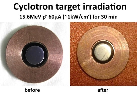
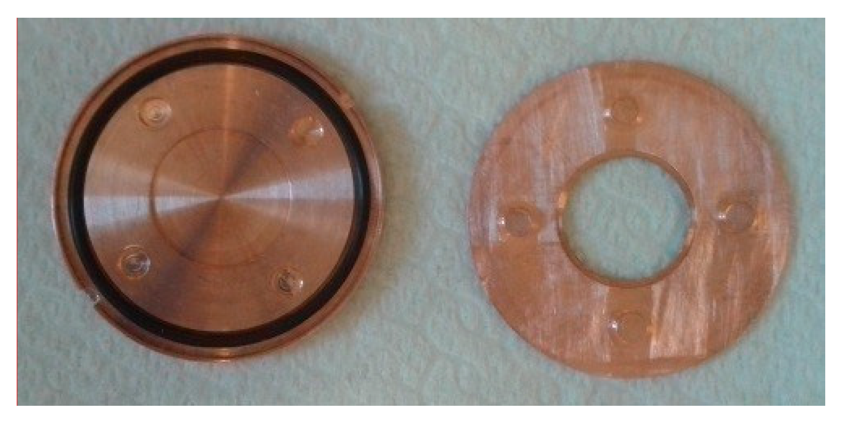
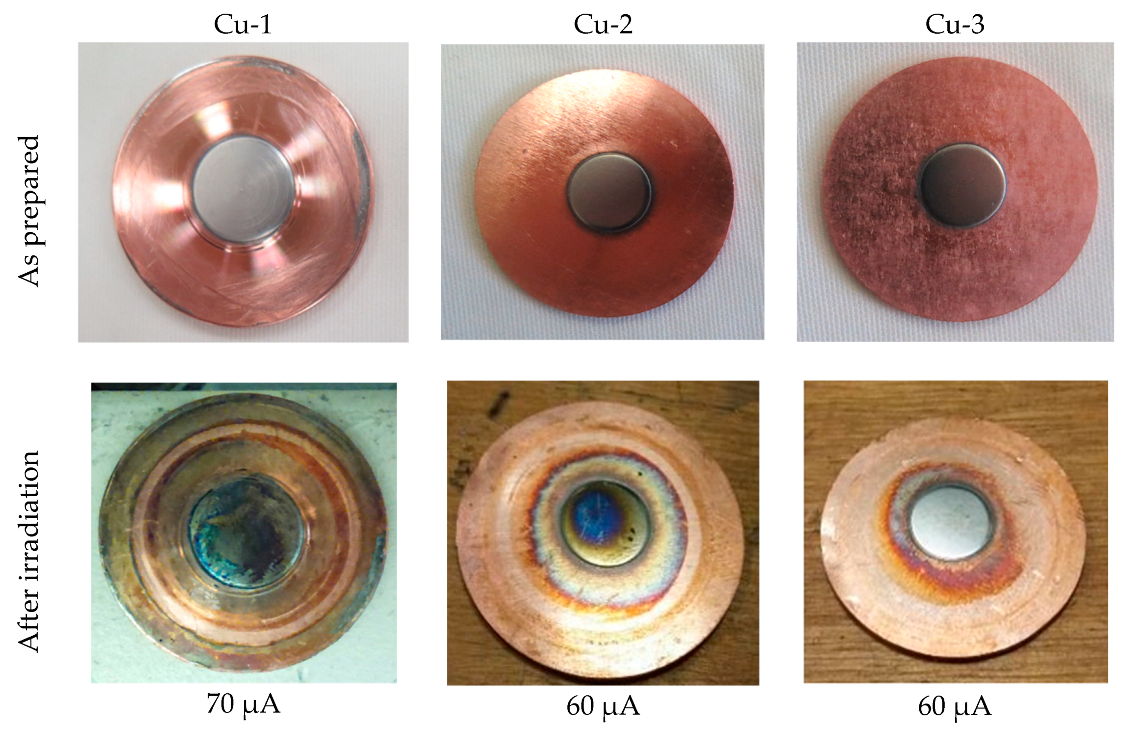
| LNL-INFN 7 | GE PETtrace | The first prototype of TEMA solid target | 70 µA, 16 MeV, 30 min, 1 kW/cm2 | natMo bulk | Cu | Magnetron sputtering of natMo | For the moment work only with natMo | [5] | |
| Iran | RRDL, NSTRI 8 | Cyclone-30 | Inclined target | 160 µA, 25 MeV, 1000 µA-h | natMo | Cu | Thermal spray 130 µm Mo | Not inert backing | [26] |
| Poland | RC POLATOM 9 | GE PETtrace 870 | 2.5/5.7 µA for 100Mo target | - | natMo | Pt | Electrodeposition from aqueous solutions | Only oxide is deposited | [5] |
| natMo powders | - | Pressing, sintering pellet, preliminary H2 treatment 166 °C; 50–78% density After H2 treatment was improved | Considerable oxide-low thermal conductivity | [4,5] | |||||
| - | - | Electrodeposition from molten salts LICl-NaCl-KCl-MoCl3 600 °C on Ni plate in argon gave low oxidation | No data on thickness and quality | [4] | |||||
| - | Mechanical reshaping: melting, remelting, rolling, annealing in vacuum. Different thickness 0.25–600 µm. H2 treatment before remelting. Heating in an envelope of SS. | Lamination technological difficulties | [31] | ||||||
| Institute of Metallurgy and Mat. Sci. | Mo-Zn alloy | Mo-Zn alloys co-electrodeposited from citrate solutions | Not pure Mo | [22] | |||||
| USA | – | – | – | – | Pt | Electroplating from alkaline solutions | A mixture of oxide and metal. Not pure metal | [20] | |
| Washington University | CS–15 | – | 10–15 MeV 3,4,5µA | 100Mo2C | Pt | 100Mo2C synthesized from 100MoO3 using 3 steps thermal carburization method; pressed on Pt target holder (5000 psi for 30 s) | Low beam current and irradiation time | [4,5] | |
| Massachusetts Institute of Technology | – | – | – | – | – | Electrodeposition: Pre-electrolysis + Electrodeposition of Mo. K3MoCl6 (source of soluble Mo) and KCl (a principal constituent of the supporting electrolyte) –> thickness 0.5 mm, columnar structure, but the presence of protrusion on the surface | No limitation on the thickness, but the process is complicated and contaminants are present. | [23] | |
| Syria | – | – | Inclined elliptical IBA blank copper target | – | MoO2 | Cu | Electroplating from aqueous solution. | A very thin layer, poor adherence, oxidation | [4,5] |
| – | natMoO3 oxide | Cu | Pressing, sintering 750 °C 50 µm MoO3 | Backing not inert | [5] | ||||
| 100 µA, 3 h | natMo powders | Cu | Pressing Mo powders | Backing not inert | [4] | ||||
| Germany | GSI 10 | – | – | – | 100Mo, 92Mo, 98Mo | C or Cu | FIB sputtering with Ar+ Sletten–Type apparatus. 0.1/0.14 µm films also self–sustaining | Small thickness reported | [27] |
| Sektion Physik Universitat Munchen | – | – | – | 100Mo, 98Mo | Cu backing or self–sustaining | High vacuum sputter deposition with 10 keV Xe + gun. 100–400 nm thick films/foils | 100–400-nm-thick films/foils | [29] | |
| UK | Mallinckrodt Llc 11 | – | – | – | 100Mo metallic, MoO3 or their combination | – | Target obtained from commercial supplier (probably material) | No data on irradiation | [13] |
| Daresbury Laboratory | – | – | – | 100Mo | – | Rolling from powders. Thickness is about 0.5 and 10 µm thick | About 0.5 and 10 µm thick | [28] | |
| Romania | Institute of physical chemistry | – | – | – | 0.01 mm quite dense, adherent. | Metal | Electrodeposition from molten salts NaCl-KCl-NaF K2MoO4 1123 K on Ni plate in argon produced low oxidation | Difficult preparation, expensive equipment | [24] |
| Sputtering Parameter | natMo |
|---|---|
| Argon flux (sccm) | 17 |
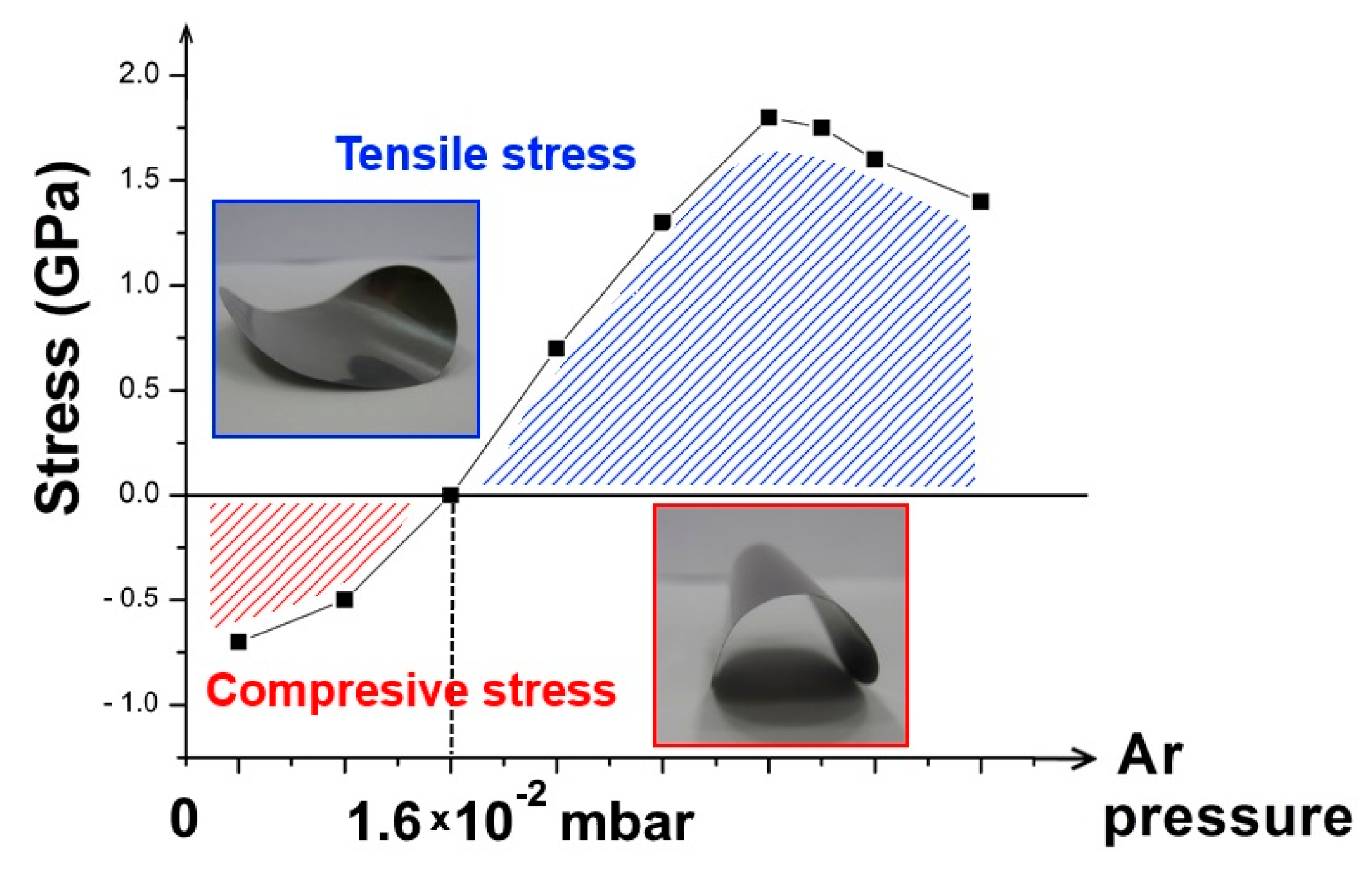
| Argon pressure (mbar) | 1.63 × 10⁻² |
| Power (W) | 5–550 |
| Target-substrate distance (cm) | 6 |
| Substrate temperature (°C) | 500 |
| Deposition rate (µm/h) | 11 |
| Program for multilayer | Yes |
| Prototype Name | Ceramic (Inert) Part | Ceramic Dimensions (mm) | Mo Film Thickness (µm) | Irradiation Current (µA) | Irradiation Time (min) | Notes |
|---|---|---|---|---|---|---|
| Cu-1 | – | – | 110 | 30 | 1 | Resisted |
| 50 | 1 | Resisted | ||||
| 70 | 1 | Resisted | ||||
| Cu-2 | – | – | 125 | 60 | 1 | Resisted |
| Cu-3 | – | – | 125 | 60 | 1 | Resisted |
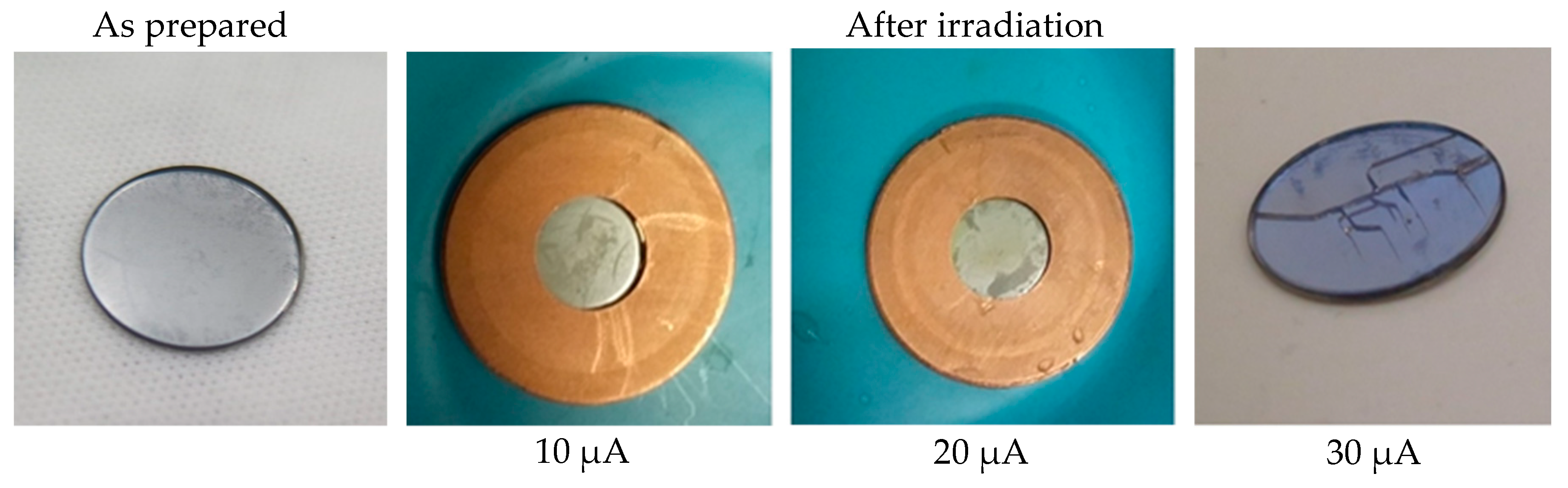
| *S-1 | Sapphire | Ø12.7 × 0.5 | 90 | 10 | 1 | Resisted |
| 20 | 1 | Resisted | ||||
| 30 | 1 | Cracked | ||||
| *S-2 | Sapphire | Ø12.7 × 0.5 | 90 | 50 | 1 | Cracked |
| S-3 | Sapphire brazed | Ø12.7 × 0.5 | 110 | 30 | 1 | Resisted |
| 40 | 1 | Resisted | ||||
| 60 | 1 | Resisted | ||||
| S-4 | Sapphire brazed | Ø12.7 × 0.5 | 125 | 60 | 1 | Cracked |
| S-5 | Sapphire brazed | Ø12.7 × 0.5 | 125 | 60 | 1 | Resisted |
| * D-0 | Diamond | Ø13.5 × 0.3 | – | 20 | 1 | Resisted |
| D-1 | Diamond brazed | Ø13.5 × 0.3 | 125 | 20 | 1 | Resisted |
| 40 | 1 | Resisted | ||||
| 60 | 1 | Resisted | ||||
| D-2 | Diamond brazed | Ø13.5 × 0.3 | 125 | 60 | 30 | Resisted |
| Nuclide Name | ID Confidence | Energy (keV) | Yield (%) |
|---|---|---|---|
| Nb–92m | 0.998 | 934.46 | 99.00 |
| Tc–94 | 0.902 | 702.62 | 99.60 |
| 849.74 | 95.70 | ||
| 871.09 | 100.00 | ||
| 1592.10 | 2.25 | ||
| Tc–95 | 0.992 | 765.79 | 93.82 |
| 947.67 | 1.95 | ||
| 1073.71 | 3.74 | ||
| Tc–95m | 0.999 | 204.12 | 63.25 |
| 582.08 | 29.96 | ||
| 820.62 | 4.71 | ||
| 835.15 | 26.63 | ||
| Tc–96 | 0.985 | 314.34 | 2.43 |
| 778.22 | 100.00 | ||
| 812.58 | 82.00 | ||
| 849.93 | 98.00 | ||
| 1091.35 | 1.10 | ||
| 1126.96 | 15.20 | ||
| Mo–99 | 0.981 | 140.51 | 89.43 |
| 181.06 | 5.99 | ||
| 739.50 | 12.13 | ||
| 777.92 | 4.26 | ||
| Tc–99m | 0.936 | 140.51 | 89.00 |
© 2018 by the authors. Licensee MDPI, Basel, Switzerland. This article is an open access article distributed under the terms and conditions of the Creative Commons Attribution (CC BY) license (http://creativecommons.org/licenses/by/4.0/).
Share and Cite
Skliarova, H.; Cisternino, S.; Cicoria, G.; Marengo, M.; Palmieri, V. Innovative Target for Production of Technetium-99m by Biomedical Cyclotron. Molecules 2019, 24, 25. https://doi.org/10.3390/molecules24010025
Skliarova H, Cisternino S, Cicoria G, Marengo M, Palmieri V. Innovative Target for Production of Technetium-99m by Biomedical Cyclotron. Molecules. 2019; 24(1):25. https://doi.org/10.3390/molecules24010025
Chicago/Turabian StyleSkliarova, Hanna, Sara Cisternino, Gianfranco Cicoria, Mario Marengo, and Vincenzo Palmieri. 2019. "Innovative Target for Production of Technetium-99m by Biomedical Cyclotron" Molecules 24, no. 1: 25. https://doi.org/10.3390/molecules24010025