
Chemical Kinetic Model of Multicomponent Gasoline Surrogate Fuel with Nitric Oxide in HCCI Combustion

Key Laboratory of Low-grade Energy Utilization Technologies and Systems, Ministry of Education, Chongqing University, Chongqing 400044, China
*
Author to whom correspondence should be addressed.
Molecules 2020, 25(10), 2273; https://doi.org/10.3390/molecules25102273
Submission received: 15 April 2020
/
Revised: 2 May 2020
/
Accepted: 3 May 2020
/
Published: 12 May 2020
(This article belongs to the Special Issue 25th Anniversary of Molecules—Recent Advances in Green Chemistry)
Abstract
:This study presents a simplified mechanism of a five-component gasoline surrogate fuel (TDRF–NO) that includes n-heptane, isooctane, toluene, diisobutylene (DIB) and nitric oxide (NO). The mechanism consists of 119 species and 266 reactions and involves TDRF and NO submechanisms. Satisfactory results were obtained in simulating HCCI combustion in engines. The TDRF submechanism is based on the simplified mechanism of toluene reference fuel (TRF) and adds DIB to form quaternary surrogate fuel for gasoline. A simplified NO submechanism containing 33 reactions was added to the simplified mechanism of TDRF, considering the effect of active molecular NO on the combustion of gasoline fuel. The ignition delay data of the shock tube under different pressure and temperature conditions verified the validity of the model. Model verification results showed that the ignition delay time predicted by the simplified mechanism and its submechanics were consistent with the experimental data. The addition of NO caused the ignition delay time of the mechanism simulation to advance with increasing concentration of NO added. The established simplified mechanism effectively predicted the actual combustion and ignition of gasoline.
1. Introduction
Compared with traditional compression ignition (CI) and spark ignition (SI) engines, homogeneous charge compression ignition (HCCI) engines have become a focus of research among internal combustion engines because of their efficient and clean combustion methods. However, combustion of HCCI is sensitive, and slight changes in the mixture state in the cylinder greatly affect the combustion [1]. In addition, HCCI has problems, such as a narrow range of operating conditions, difficulty in catching fire and high HC and CO emissions in HCCI combustion.
To solve these problems, scholars have adopted various advanced technologies such as intake air heating [2] and increasing the compression ratio of internal combustion engines [3], control strategy with dual fuel [4] and simulation of surrogate fuels [5]. The use of numerical simulation with chemical kinetics as the core is one of the most appropriate means to explore combustion mechanism and help achieve accurate control of HCCI.
Gasoline is a complex mixture that contains hundreds of hydrocarbons, including olefins, naphthenes, alkanes and aromatics. The study of the chemical kinetic mechanism of gasoline is complicated. Increasing the number of components will exponentially increase the reaction, material and thermophysical parameters; hundreds of components in gasoline will complicate the reaction mechanism to an unacceptable level [6]. Therefore, using one or several components to describe the physicochemical properties of gasoline fuel has become a feasible research trend.
Isooctane is the first considered surrogate fuel for research on selecting gasoline substitute mixture components. Isooctane has a high-octane number and is widely used in gasoline HCCI combustion simulations [7]. Galmiche et al. [8] and Liu et al. [9] constructed a simplified kinetic model for HCCI combustion of isooctane to control the ignition delay time of fuel in the shock tube and predict the heat rate and fuel consumption. The octane number of isooctane is fixed (RON = MON = 100) and thus cannot reflect the important characteristic of gasoline octane change.
The cetane number of n-heptane is similar to that of diesel oil [8] and can be used to match the octane number of gasoline fuel by mixing different ratios of n-heptane and isooctane. The mixture is called primary reference fuel (PRF). Scholars have conducted much research on the kinetic model of PRF chemical reaction [10,11,12]. The experimental results of Risberg et al. [13] showed that a large difference exists in flame stability between PRF and gasoline; moreover, the laminar flame propagation speed of PRF is higher than that of standard gasoline. To better simulate the combustion of gasoline HCCI, researchers have proposed a mixture of three materials, namely, isooctane, n-heptane and toluene, as surrogate fuel (toluene reference fuel (TRF)) for gasoline [14,15,16].
Andrae et al. [14] added the PRF skeletal mechanism to the detailed toluene mechanism and obtained a TRF mechanism containing 1121 species and 4961 reactions. The prediction results of this mechanism are consistent with the experimental results of ignition delay time in shock tube, fast compressor and HCCI engine. Zhang et al. [15] proposed a simplified TRF mechanism with 70 components and 196 reactions for HCCI conditions. Gasoline three-component surrogate fuel containing n-heptane, isooctane, and toluene was used in shock tubes. The ignition delay time was also verified. Coskun et al. [16] used the TRF chemical kinetic mechanism consisting of 137 species and 633 reactions to study the effects of various initial conditions and fuel/air equivalent ratios (ϕ) on the combustion and emission characteristics of HCCI engines.
Considering the representative components of olefins in actual gasoline, many scholars added diisobutylene (DIB) as a representative of olefins to TRF for forming a quaternary alternative fuel for gasoline. This quaternary fuel is referred to as TDRF. Fikri et al. [17] conducted shock tube experiments with multiple groups of gasoline substitute mixtures of TDRF fuel under different mixing conditions. The results showed that the ignition delay of the quaternary TDRF fuel (20% n-heptane/25% isooctane/45% toluene/10% diisobutene by liquid volume) was closest to actual gasoline. The experimental data of the ignition delay time in shock tube can be used to verify the mechanism of the quaternary gasoline surrogate mixture.
HCCI combustion is a lean, low-temperature combustion process controlled by the fuel’s chemical reaction kinetics, which plays a vital role in the entire combustion process and emission. As important components of the burned exhaust gas, NO exhibits active chemical properties that affect HCCI combustion.
The interaction between NO and small-molecular hydrocarbon fuels was first studied [18,19]. Frassoldati et al. [19] simulated the interaction between NO and hydrocarbon fuels at high temperature by using chemical kinetics and obtained NO cross reaction with C1–C4 fuel. Gasoline contains a large number of macromolecular hydrocarbons, so the interaction between NO and macroalkanes is also discussed in detail [20,21,22,23].
Wang et al. [20] experimentally investigated the effect of NO on the HCCI combustion of n-heptane and isooctane. Contino et al. [23] used a PRF-NO chemical reaction kinetic model to analyze the effect of NO on isooctane oxidation. Zheng et al. [24] constructed a simplified mechanism of TRF–NO containing 80 species and 184 reactions; they compared the simulated and experimental values of TRF–NO under different operating conditions and found that the simplified mechanism of TRF–NO can better reflect the tendency of the ignition delay time of HCCI engines to change with the concentration of NO added.
Few studies are available on the chemical kinetic mechanism of TDRF–NO. Exploring the TDRF–NO mechanism can increase understanding of the HCCI combustion mechanism of gasoline engines and has profound significance for studying the relationship between gasoline substitutes and NO.
In this study, NO and TDRF (i.e., n-heptane, isooctane, toluene and diisobutylene) were selected as research objects. First, a DIB simplification mechanism was added based on the predecessor TRF simplification mechanism. Temperature sensitivity and reaction path were analyzed to determine key reactions and influence of NO on DIB. The reaction mechanism of TDRF–NO was constructed and the calculation results were compared with experimental values under different working conditions to verify the effectiveness of the construction mechanism.
2. Results and Discussion
The mechanism of TDRF–NO includes two parts, TDRF and NO submechanisms. Surrogate fuel TDRF (i.e., n-heptane, isooctane, toluene and diisobutylene) can better simulate the ignition characteristics of gasoline, and addition of NO can make the ignition delay time advance with the increase in concentration. In our previous research, a simplified TRF mechanism was constructed, and the mechanism was verified under shock tube conditions [25]. We added the DIB and NO submechanisms. The verification results showed that the model and experimental data had a good consistency in ignition delay time. Moreover, the ignition delay time of the model agreed well with the experimental data.
2.1. DIB Submechanism
DIB is a mixture of two conjugated olefins, 2,4,4-trimethyl-1-pentene (JC8H16) and 2,4,4-trimethyl-2-pentene (IC8H16). The chemical kinetic mechanism of some TDRF fuels only considers JC8H16. Basing on the detailed mechanism of DIB, we simplified the IC8H16 mechanism in the detailed mechanism of DIB by using two methods, reaction rate and temperature sensitivity analyses. The simplified chemical kinetic model consists 37 species and 34 reactions and is combined with the existing simplified chemical kinetic model of JC8H16 [26] to construct a complete simplified DIB model.
The detailed chemical reaction kinetics of IC8H16 used in the simulation calculations was derived from the research results of Metcalfe et al. [27]. Figure 1 shows the verification of IC8H16 ignition delay time by Metcalfe et al. [27]. Under the conditions of equivalent ratio (ϕ) of 0.5 and pressure of 4.0 atm, the calculated ignition delay time of IC8H16 showed good agreement with the experimental value. The correctness of this detailed mechanism was verified.
2.1.1. Analysis of the Reaction Path of IC8H16
To analyze the reaction path of IC8H16, we selected a single cylinder water-cooled direct injection engine as the numerical simulation object. The main technical parameters are shown in Table 1. The calculation start time was the intake valve closing (−141.5 °CA), and the calculation interval was 190 °CA. The mixture in the cylinder was assumed to be evenly distributed after the engine intake valve was closed. A homogeneous internal combustion engine model was selected in the zero-dimensional simulation software. An air/fuel equivalent ratio of 0.25 was selected to analyze the main reaction path of IC8H16, and the obtained main reaction path was added to the simplified mechanism of IC8H16 to be constructed.
The reaction rates of IC8H16 consumption are shown in Figure 2. IC8H16 was mainly consumed by the H-atom abstraction reactions by OH radical (R3609 and R3610) forming two isomers (IC8H15−A and JC8H15−B). In addition, the maximum reaction rate was the decarburization reaction (R3601). The products of R3601 are YC7H13−Y2 and CH3. The other reactions are ignored for the purpose of simplification. The main chemical reaction formulas are as follows:
R3601. IC8H16 = YC7H13 − Y2 + CH3
R3609. IC8H16 + OH = IC8H15 − A + H2O
R3610. IC8H16 + OH = JC8H15 − B + H2O
Figure 3 shows the reaction rates for the related reactions of the three products of IC8H16. Figure 3a shows that the consumption reaction rates of YC7H13−Y2. YC7H13−Y2 is mainly consumed by the decomposition reaction (R3665). The products of R3665 are DMPD13 and H-atom. Figure 3b,c shows that the main consumption reaction of JC8H15−B and IC8H15−A were R3649 and R3651, respectively. The products of both reactions are DMPD13 and methyl. The other reactions are ignored for the purpose of simplification. The main chemical reaction formulas are as follows:
R3665. DMPD13 + H = YC7H13 − Y2
R3649. DMPD13 + CH3 = JC8H15 − B
R3651. DMPD13 + CH3 = IC8H15 − A
IC8H16 undergoes dehydrogenation and decarburization reactions. Although different intermediate products exist, the same substance (DMPD13) was finally formed. In the next work, we continued to analyze the reaction path of DMPD13 and its products and finally obtained the reaction path of IC8H16, as shown in Figure 4.
2.1.2. Temperature Sensitivity Analysis of IC8H16
In HCCI engine combustion, temperature is an important factor that affects fuel combustion. We used the temperature sensitivity analysis method to analyze the detailed mechanism of IC8H16. We also changed the initial temperature in the engine and shock tube models to find the response that had a greater effect on temperature changes.
The engine parameters are shown in Table 1. The reactions with greater reaction temperature sensitivity were found at initial temperatures of 400 and 450 K. Figure 5 shows the result of temperature sensitivity analysis on IC8H16 under the conditions of HCCI engine with initial temperatures of 400 and 450 K. The pressure was 1.5 atm and the equivalent ratio ϕ was 0.25, the air used in the experiment was composed of 21% O2 and 79% N2. Eleven elementary reactions had a significant effect on the temperature in the engine cylinder (in Figure 5).
Figure 6 shows the calculation results of temperature sensitivity in the shock tube model. The initial parameters of the model were as follows: the initial temperatures were 1240 and 1500 K, the pressure was 4 atm and the molar fractions of the mixed fuel components were IC8H16: 0.75% and O2: 18%, the rest of the tube was filled with inert gas Ar. In the temperature sensitivity analysis of the shock tube model, 10 elementary reactions with large sensitivity coefficients appeared and five of them (i.e., R17, R20, R3615, R3615 and R24) were new reaction.
The new reactions obtained from the temperature sensitivity analysis of the shock tube model were not all added to the simplified mechanism. Instead, different reaction combinations were applied. After adding reaction R3615, the simplified mechanism simulation results were compared and showed good agreement with the experimental results. The reaction mechanism of the formula was added as follows:
R3615. IC8H16 + H = JC8H15 − B + H2
2.2. NO Submechanism
The effects of NO on the combustion process of n-heptane, isooctane and toluene have been analyzed by Zheng et al. [24], and a NO mechanism including 23 reactions has been constructed. Figure 7 shows the main reaction path for NO. The simulation showed that the active molecule NO changed some chemical reaction paths during fuel combustion and promoted the accumulation of OH at the initial stage of the reaction, thereby promoting the combustion.
The related reaction between NO and DIB was added on the basis of the NO submechanism proposed by Zheng et al. [24]. The reaction was combined with the TDRF simplified mechanism previously made into the TDRF–NO mechanism.
Contino et al. [23] found that NO and its derivatives have no effect on the reaction of DIB macromolecular fuel and mainly react with small molecules produced by the consumption of DIB. The mechanisms of the three substances C3H3, CH4 and CH2OH react with NO as follows:
C3H3 + N = HCN + C2H2
CH3 + HONO = CH4 + NO2
H2CNO2 + OH = CH2OH + NO2
Two new substances, namely, HCN and H2CNO2, appeared in the reaction mechanism. The reaction rate analysis of the two substances was required to find their main generation and reaction paths. The simulated HCCI engine parameters are shown in Table 1. The NO concentration was 50 ppmv.
Figure 8a shows the reaction rate of HCN. The reaction R4341 (HCCO + NO = HCN + CO2) had the highest generation rate, and HCCO and NO reacted to form HCN. The reaction R4364 (HCN + O = NCO + H) had the highest consumption rate, and HCN oxidized NCO and generated a hydrogen (H). Figure 8b shows the main reaction rate of NCO. The reactions R4398 (NCO + O = NO + CO) and R4401 (NCO + M = N + CO + M) had the highest reaction rate, and NCO generated N, NO and CO.
Figure 9a shows the reaction rate of H2CNO2. The reaction R4446 (CH3NO2 + OH = H2CNO2 + H2O) had the highest rate of formation, and CH3NO2 and OH reacted to dehydrogenate to form H2CNO2. The reaction R4457 (H2CNO2 = CH2O + NO) had the largest rate of consumption, and H2CNO2 was decomposed into CH2O and NO. Figure 9b shows the reaction rate of CH3NO2. The reaction R4439 (CH3NO2 [+M] = CH3 + NO2 [+M]) had the highest reaction rate. CH3 and NO2 combined to form CH3NO2. After the crank angle was −23 °CA, the reaction direction changed. CH3NO2 was decomposed into CH3 and NO2.
The related reactions obtained were combined with the NO mechanism proposed by Zheng et al. [24]; the mechanism constituted a NO mechanism including 33 reactions and was coupled with the simplified mechanism of TDRF produced earlier to include 266 reactions of 119 species. Finally, a simplified chemical kinetic mechanism of TDRF–NO was obtained (shown in Supplementary Material).
2.3. Validation of the Mechanism
Table 2 shows the volume ratio of each component of the surrogate fuels during the verification process.
The ability to predict the ignition delay time is an important indicator of the effectiveness of a chemical kinetic mechanism. Basing on previous studies, we constructed a simplified TDRF–NO chemical kinetic model containing five substances and verified the model and its submodels. All numerical simulations used the zero-dimensional single-region model as the calculation model in zero-dimensional software.
2.3.1. TRF Submechanism Verification
The TRF mechanism used in this study was derived from the TRF part of the TDRF mechanism constructed by Zheng and Liang [25]. Gauthier et al. [28] performed shock tube experiments with various ratios of gasoline surrogates and obtained their ignition delay time. The gasoline surrogate TRF ratio used in the experiment is shown in Table 2 for Surrogate A and B. Figure 10 shows the comparison of the ignition delay simulation results of the simplified TRF mechanism with the experimental data of Gauthier et al. [28]. The initial temperature range of the ignition delay test was 850–1200 K. The pressure range of 1.5–6.0 MPa and the equivalent ratio ϕ was 1. The air used in the experiment was composed of 21% O2 and 79% N2.
Pressure scaling of all data points within a certain pressure range can unify the independent variables of the data displayed by the graph. The pressure scaling is generally assumed as a power function law (Equation (11)).
where τp* is the ignition delay time from standard to pressure P*, τ is the ignition delay time, P is the experimental pressure, P* is the standard pressure and N is the pressure scaling factor.
Gauthier et al. [28] reported the following pressure scaling factors for two surrogates: mixed Surrogate A was 0.83 and Surrogate B was 0.96. Pressure scaling standard to 5.5 MPa. Figure 10 shows that the simplified mechanism can reflect the trend of the ignition delay time with the initial temperature for different ratios of TRFs well. This mechanism had a large error in the high-temperature conditions of the mixed Surrogate A and agreed well with the experimental results at low-temperature conditions (Figure 10a). The simulation results using the Surrogate B agreed well with the experimental results (Figure 10b). This mechanism can be used as the TRF part of the simplified mechanism of TDRF.
2.3.2. DIB Submechanism Verification
In this study, the mechanism of DIB was verified using shock tube experimental data obtained by Metcalfe et al. [27]. The simplified mechanism constructed was compared with the detailed mechanism to further illustrate the effectiveness of the mechanism. The comparison between the experimental data and the simplified and detailed mechanism simulation results of the shock tube in the temperature range of 1200–1500 K is shown in Figure 11. The experimental pressure was 4 atm and the equivalent ratio was 0.5. Table 3 shows the mole ratio of the two isomers of DIB. The simplified mechanism of JC8H16 used in the simulation was from Zhong et al. [26].
In Figure 11a, we compared the simplified and detailed mechanism of IC8H16 and experimental data of Fuel1. The general trend of the three sets of data were the same and the simplified mechanism and experimental data agreed well, especially around 1200 K to 1500 K.
Figure 11b shows the comparison of the simulation and experimental ignition delay of Fuel2. The simplified mechanism of JC8H16 used in the simulation is from Zhong et al. [26]. Most of the data of the simplified mechanism were consistent with the experimental results and the simulation error was smaller than the detailed mechanism.
Figure 11c is the comparison of the experimental and simulated ignition delay of Fuel3. The mole fraction ratio of JC8H16 and IC8H16 mixed fuel was 3:1. The simplification mechanism and experimental results agreed at different operating conditions, which indicated that the simulation results of the simplification mechanism of DIB constructed in this study were good and could be used to construct the TDRF simplification mechanism.
2.3.3. TDRF-Simplified Mechanism Verification
In the previous work, we obtained a quaternary simplified mechanism containing 233 reactions of 133 species. The validity of the mechanism is verified below. This study used the experimental data of the ignition delay of the shock tube of quaternary gasoline substitute TDRF reported by Fikri et al. [17]. The fuel mixture (Surrogate D) used for the experiment ratio of the components is shown in Table 2.
The initial temperature range of the shock tube experiment was 700–1200 K. The experimental pressure was about 10, 30 and 50 bar and the equivalent ratio ϕ was 1. The air used in the experiment was composed of 21% O2 and 79% N2. Figure 12 shows the comparison of the ignition delay times between the experimental results in shock tube by Fikri et al. [17] and the four computational results obtained using the detailed mechanism of Cancino et al. [30], the detailed and semidetailed mechanisms of Andrea et al. [14,31], and the simplified mechanism of TDRF proposed in the present study. The pressure standard was set to 30 bars. The pressure scaling factor was 0.65.
Figure 12 also shows that the four mechanisms can reflect the trend of ignition delay time with temperature well around three initial pressures. The simplified mechanism of TDRF constructed in the present study and the detailed mechanism of Cancino et al. [30] showed a good agreement with the experimentally measured ignition delay time as a whole. The simplified model can show the change of ignition delay time with the initial temperature and pressure of the shock tube well.
2.3.4. TDRF–NO-Simplified Mechanism Verification
Finally, the TDRF mechanism coupled with the NO submechanism constituted a simplified TDRF–NO chemical kinetic mechanism with 119 species and 266 reactions (shown in Supplementary Material).
Pera et al. [29] studied the ratio of ternary TRF fuel to gasoline and obtained the proportion of each component of the TRF fuel (Surrogate C), as shown in Table 2. This ratio was obtained from the H/C ratio of the blended gasoline and the octane number. The proportion of each component of TDRF fuel (Surrogate D) in Table 2 was from Fikri et al. [17].
Figure 13 presents the comparison of the calculated values of the simplified mechanism of TDRF–NO constructed by using Surrogate C and the detailed mechanism of Cancino et al. [30] with the experimental values of gasoline experiments under the experimental conditions of Risberg et al. [13], and it also shows that both models could simulate the effect of NO on gasoline fuel combustion at this ratio. However, the data of the simplified mechanism were consistent with the experimental results and the simulation error was smaller than the detailed mechanism.
Figure 14 shows the comparison of the ignition delay time of Surrogate D under TDRF-simplified and detailed mechanisms with the concentration of NO added under two design conditions. The two conditions are as follows: Condition 1, ϕ = 0.25, initial pressure of 4 atm and initial temperature of 600 K; Condition 2, ϕ = 0.25, initial pressure of 2 atm and initial temperature of 800 K.
Given that no experimental data of TDRF–NO are available, this article only compared the simplified and detailed mechanisms. Figure 14 shows that the simplified and detailed mechanism simulations had the same trend with increasing NO concentration. As the concentration of NO increased, the ignition increased. The simplified and detailed mechanisms agreed well at each operating point, whereas the simplified mechanism had only 134 reactions. Compared with the detailed mechanism, the simplified mechanism is within the error range required by simulation and it could simulate the combustion of fuel and saved much of the calculation costs, reflecting the superiority of the simplified mechanism.
3. Materials and Methods
3.1. Zero-Dimensional Simulation Software
This study used zero-dimensional simulation software (Sandia National Laboratories, Albuquerque, NM, USA, 1980) to calculate the fuel combustion process. Figure 15 shows the flow of the simulation solution process. The thermodynamic data were read by the preprocessor of the gas phase dynamics to generate a link file that containing elements, components and their thermodynamic data information. The reaction mechanism was read by the surface dynamics preprocessor (in software) to form a link file containing surface reaction information. The preprocessor of the transfer process automatically reads the transfer data from the database in software based on the information in the gas dynamics connection file to generate a transfer connection file containing the transfer information.
The transport subroutine library (in software) and the reaction subroutine library (in software) store the above-mentioned transport data and the information in the link file into a matrix, and then calculated the corresponding physical parameters. Finally, the governing equations were solved.
3.2. Source of Kinetic Mechanisms
The TRF mechanism used in this study was derived from the TRF part of the TDRF mechanism constructed by Zheng and Liang [25]. The gasoline surrogate TRF ratio used in the experiment is Surrogate A (17% n-heptane/63% isooctane/20% toluene by liquid volume), Surrogate B (17% n-heptane/69% isooctane/14% toluene by liquid volume) and Surrogate C (17% n-heptane/69% isooctane/14% toluene by liquid volume).
DIB is a mixture of two conjugated olefins, JC8H16 and IC8H16. The detailed chemical reaction kinetics of IC8H16 used in the simulation calculations was derived from the research results of Metcalfe et al. [27] who used a mechanism that includes 897 species and 3783 reactions. The simplified mechanism of JC8H16 used in the simulation is from Zhong et al. [26].
The gasoline surrogate TDRF ratio used in the experiment is Surrogate D (25% n-heptane/20% isooctane/45% toluene/10% diisobutene by liquid volume).
The NO submechanism was based on the report of Zheng et al. [24] NO submechanism. The related reaction between NO and DIB was added on the basis of the NO submechanism proposed by Zheng et al. The reaction was combined with the TDRF simplified mechanism into the TDRF–NO mechanism.
3.3. Simplified Calculation Method
3.3.1. Rate of Production Analysis
Rate of Production (ROP) analysis was to analyze the effect of the elementary reaction on the net generation rate of a component, so that several important elementary reactions on the component can be obtained relatively quickly. The calculation formula of the chemical reaction generation rate and the influence coefficient of the chemical reaction generation rate was as follows:
where represents the chemical reaction rate of the i-th element reaction, represents the chemical equivalent coefficient, represents the effect of the chemical reaction rate component k generation rate of the i-th element reaction and I represents all the number of elementary reactions containing component k.
During the reaction, the ROP coefficient can be used to compare the effect of the elementary reaction on the net formation rate of the component. When was positive, it means that the elementary reaction promotes the formation of a certain component. When was negative, it means that the elementary reaction promotes the consumption of a certain component.
3.3.2. Sensitivity Analysis
The sensitivity analysis method was used to analyze and obtain the reaction with greater sensitivity to the parameter changes in the reaction system and to know whether a certain elementary reaction promotes the fuel combustion process. The sensitivity orthogonal coefficient of the j-th elementary reaction can be obtained by the following formula:
where represents the chemical reaction rate constant of the j-th element reaction in the chemical reaction mechanism and represents the concentration of the i-th substance in the chemical reaction mechanism.
3.4. Mechanism Verification Method
The ability to predict the ignition delay time is an important indicator of the effectiveness of a chemical kinetic mechanism. In this study, the mechanism was verified using shock tube experimental data obtained by previous research.
4. Conclusions
A component DIB was added based on the simplified mechanism of TRF to construct a simplified mechanism of TDRF. Considering the effect of active molecular NO on the combustion process of gasoline fuel, we constructed a NO submechanism. A simplified TDRF–NO chemical kinetic mechanism consisting of 119 species and 266 reactions was formed by coupling the TDRF mechanism with the NO submechanism. The simplified mechanism obtained satisfactory results in the verification of the ignition delay in the shock tube.
- (1)
- A complete simplified IC8H16 mechanism was obtained by analyzing the reaction path and temperature sensitivity of IC8H16. The simplified mechanism of IC8H16 was coupled with the simplified mechanism of JC8H16 to construct a DIB submechanism. The new mechanism was compared with the experimental data and detailed mechanism, and comparison results show that the consistency of the three models was better.
- (2)
- The NO submechanism was based on our previous research of NO submechanism and related reactions of NO and DIB were added to construct a NO submechanism containing 33 reactions.
- (3)
- The TRF mechanism was derived from the TRF part of the TDRF mechanism that we constructed before and the simplified mechanism of TDRF was formed by coupling the simplified mechanism of DIB. The ignition delay time was verified under the condition of a shock tube. The model verification results were in good agreement with the experimental data.
- (4)
- The TDRF and NO submechanisms were coupled into a TDRF–NO chemical kinetic simplified mechanism. The two fuels were compared with the detailed mechanisms and experimental data. The ignition delay time of the simplified and detailed mechanism simulations increased with increasing NO concentration. The reliability of TDRF–NO simplified mechanism was illustrated.
Supplementary Materials
The following are available online. Table S1: TDRF–NO simplified mechanism.
Author Contributions
C.Y. and Z.Z. conceived and finished the article. C.Y. did the simulation experiments and prepared the manuscript. Z.Z. processed the data analyses and revised the manuscript. All authors have read and agreed to the published version of the manuscript.
Funding
This research was funded by the National Natural Science Foundation of China, Grant Number 51776024.
Conflicts of Interest
All authors state no conflict of interest.
References
- Lee, K.; Cho, S.; Kim, N.; Min, K. A study on combustion control and operating range expansion of gasoline HCCI. Energy 2015, 91, 1038–1048. [Google Scholar] [CrossRef]
- Gowthaman, S.; Sathiyagnanam, A.P. Analysis the optimum inlet air temperature for controlling homogeneous charge compression ignition (HCCI) engine. Alex. Eng. J. 2018, 57, 2209–2214. [Google Scholar] [CrossRef]
- Calam, A.; Solmaz, H.; Yılmaz, E.; Içingür, Y. Investigation of effect of compression ratio on combustion and exhaust emissions in a HCCI engine. Energy 2019, 168, 1208–1216. [Google Scholar] [CrossRef]
- Polat, S. An experimental study on combustion, engine performance and exhaust emissions in a HCCI engine fuelled with diethyl ether–ethanol fuel blends. Fuel Process. Technol. 2016, 143, 140–150. [Google Scholar] [CrossRef]
- Zhou, Y.C.; Hariharan, D.; Yang, R.N.; Mamalis, S.; Lawler, B. A predictive 0-D HCCI combustion model for ethanol, natural gas, gasoline, and primary reference fuel blends. Fuel 2019, 237, 658–675. [Google Scholar] [CrossRef]
- Andrae, J.; Johansson, D.; Björnbom, P.; Risberg, P.; Kalghatgi, G. Co-oxidation in the auto-ignition of primary reference fuels and n-heptane/toluene blends. Combust. Flame 2005, 140, 267–286. [Google Scholar] [CrossRef]
- Aleiferis, P.G.; van Romunde, Z.R. An analysis of spray development with iso-octane, n-pentane, gasoline, ethanol and n-butanol from a multi-hole injector under hot fuel conditions. Fuel 2013, 105, 143–168. [Google Scholar] [CrossRef] [Green Version]
- Galmiche, B.; Halter, F.; Foucher, F. Effects of high pressure, high temperature and dilution on laminar burning velocities and Markstein lengths of iso-octane/air mixtures. Combust. Flame 2012, 159, 3286–3299. [Google Scholar] [CrossRef]
- Liu, Y.D.; Jia, M.; Xie, M.Z.; Pang, B. Improvement on a skeletal chemical kinetic model of iso-octane for internal combustion engine by using a practical methodology. Fuel 2013, 103, 884–891. [Google Scholar] [CrossRef]
- Narayanaswamy, K.; Pepiot, P.; Pitsch, H. A chemical mechanism for low to high temperature oxidation of n-dodecane as a component of transportation fuel surrogates. Combust. Flame 2014, 161, 866–884. [Google Scholar] [CrossRef]
- Vuilleumier, D.; Kozarac, D.; Mehl, M.; Saxena, S.; William, J.P.; Robert, W.D.; Chen, Y.J.; Sarathy, S.M. Intermediate temperature heat release in an HCCI engine fueled by ethanol/n-heptane mixtures: An experimental and modeling study. Combust. Flame 2014, 161, 680–695. [Google Scholar] [CrossRef]
- Su, W.H.; Huang, H.Z. Development and calibration of a reduced chemical kinetic model of n-heptane for HCCI engine combustion. Fuel 2005, 84, 1029–1040. [Google Scholar] [CrossRef]
- Risberg, P.; Johansson, D.; Andrae, J.; Kalghatgi, G.; Björnbom, P.; Ångström, H.E. The influence of NO on the combustion phasing in an HCCI engine. Sae Tech. Pap. 2006, 2, 209–213. [Google Scholar] [CrossRef]
- Andrae, J.C.G. Development of a detailed kinetic model for gasoline surrogate fuels. Fuel 2008, 87, 2013–2022. [Google Scholar] [CrossRef]
- Zhang, Q.F.; Zheng, Z.L.; He, Z.W.; Wang, Y. Reduced Chemical Kinetic Model of Toluene Reference Fuels for HCCI Combustion. Acta Phys. Chim. Sin. 2011, 27, 530–538. [Google Scholar] [CrossRef]
- Coskun, G.; Demir, U.; Yilmaz, N.; Soyhan, H.S. Computational investigation of combustion and emission characteristics of toluene reference fuel (TRF) mixtures in an HCCI engine using stochastic reactor model. J. Braz. Soc. Mech. Sci. Eng. 2017, 39, 2935–2943. [Google Scholar] [CrossRef]
- Fikri, M.; Herzler, J.; Starke, R.; Schulz, C.; Roth, P.; Kalghatgi, G.T. Autoignition of gasoline surrogates mixtures at intermediate temperatures and high pressures. Combust. Flame 2008, 152, 276–281. [Google Scholar] [CrossRef]
- Griffiths, J.F. Reduced kinetic models and their application to practical combustion systems. Prog. Energy Combust. Sci. 1995, 21, 25–107. [Google Scholar] [CrossRef]
- Frassoldati, A.; Faravelli, T.; Ranzi, E. Kinetic modeling of the interactions between NO and hydrocarbons at high temperature. Combust. Flame 2003, 135, 97–112. [Google Scholar] [CrossRef]
- Wang, Y.; Zheng, Z.; He, Z.; Wang, F. Kinetic Modeling of Nitric Oxide Sensitization of n-heptane Auto-ignition and Combustion. Energy Sources 2015, 37, 997–1004. [Google Scholar] [CrossRef]
- Glaude, P.A.; Marinov, N.; Koshiishi, Y.; Matsungaga, N.; Hori, M. Kinetic modeling of the mutual oxidation of NO and larger alkanes at low temperature. Energy Fuels 2005, 19, 1839–1849. [Google Scholar] [CrossRef]
- Dayma, G.; Dagaut, P. Experimental and Kinetic Modeling Study of the Impact of NO and NO2 on the Oxidation of a Primary Reference Fuels Mixture. In Proceedings of the Combustion Institute, Vienna, Austria, 14–17 April 2009. [Google Scholar]
- Contino, F.; Foucher, F.; Dagaut, P.; Lucchini, T.; D’Errico, G.; Rousselle, C.M. Experimental and numerical analysis of nitric oxide effect on the ignition of iso-octane in a single cylinder HCCI engine. Combust. Flame 2013, 160, 1476–1483. [Google Scholar] [CrossRef]
- Zheng, Z.L.; Lv, Z.M. A new skeletal chemical kinetic model of gasoline surrogate fuel with nitric oxide in HCCI combustion. Appl. Energy 2015, 147, 59–66. [Google Scholar] [CrossRef]
- Zheng, Z.L.; Liang, Z.L. Reduced Chemical Kinetic Model of a Gasoline Surrogate Fuel for HCCI Combustion. Acta Phys. Chim. Sin. 2015, 31, 1265–1274. [Google Scholar] [CrossRef]
- Zhong, B.J.; Zheng, D. A chemical mechanism for ignition and oxidation of multi-component gasoline surrogate fuels. Fuel 2014, 128, 458–466. [Google Scholar] [CrossRef]
- Metcalfe, W.K.; Pitz, W.J.; Curran, H.J.; Simmie, J.M.; Westbrook, C.K. The development of a detailed chemical kinetic mechanism for diisobutylene and comparison to shock tube ignition times. Proc. Combust. Inst. 2007, 31, 377–384. [Google Scholar] [CrossRef] [Green Version]
- Gauthier, B.M.; Davidson, D.F.; Hanson, R.K. Shock tube determination of ignition delay times in full-blend and surrogate fuel mixtures. Combust. Flame 2004, 139, 300–311. [Google Scholar] [CrossRef]
- Pera, C.; Knop, V. Methodology to define gasoline surrogates dedicated to auto-ignition in engines. Fuel 2012, 96, 59–69. [Google Scholar] [CrossRef]
- Cancino, L.R.; Fikri, M.; Oliveira, A.M.; Schulz, C. Ignition delay times of ethanol-containing multi-component gasoline surrogates: Shock-tube experiments and detailed modeling. Fuel 2011, 90, 1238–1244. [Google Scholar] [CrossRef]
- Andrae, J.C.G.; Head, R.A. HCCI experiments with gasoline surrogate fuels modeled by a semidetailed chemical kinetic model. Combust. Flame 2008, 156, 842–851. [Google Scholar] [CrossRef]
Sample Availability: Simplified mechanism of the TDRF–NO are available from the authors. |
Figure 1.
IC8H16 detailed mechanism verification.
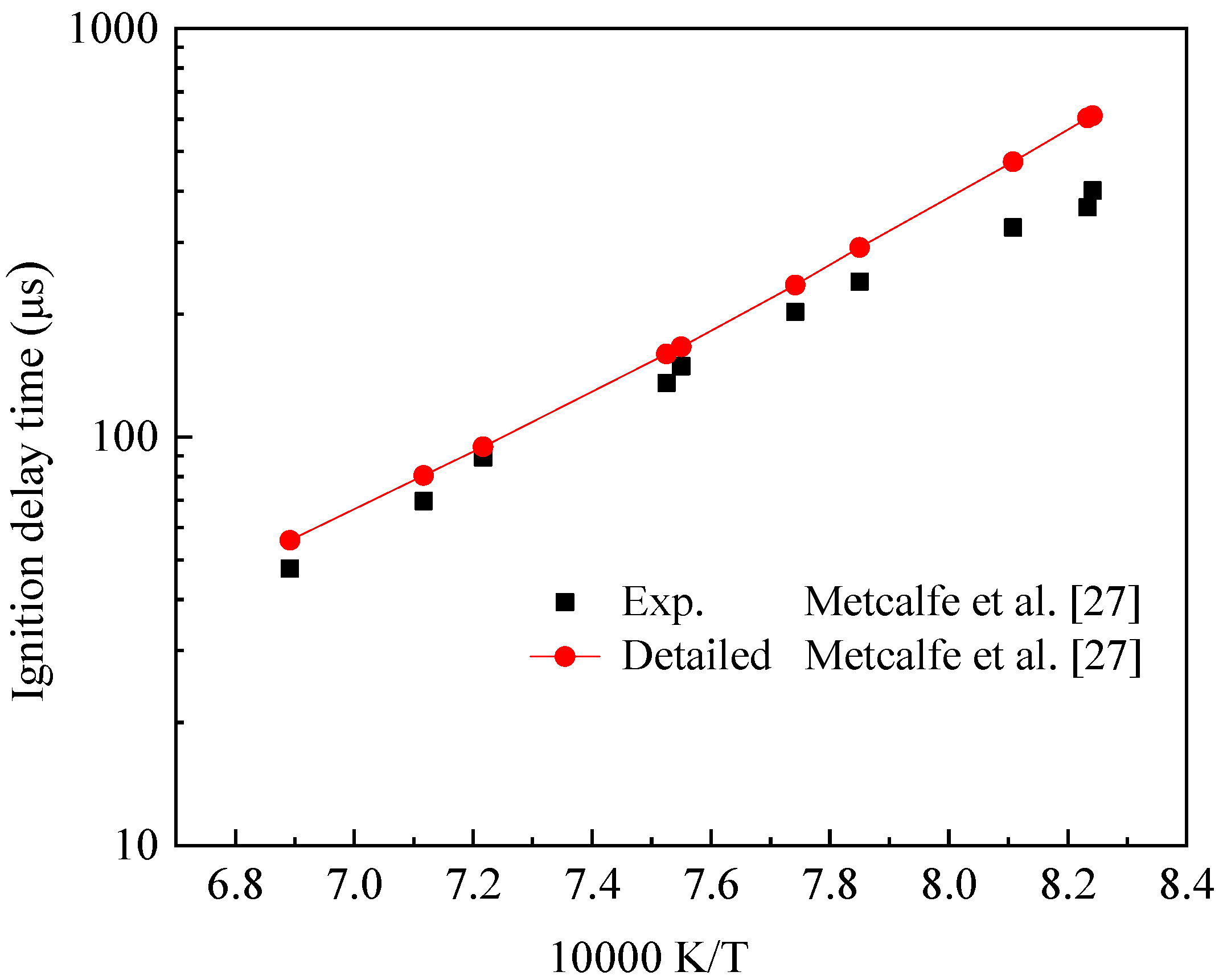
Figure 2.
Reaction rate diagram of the main reaction of IC8H16.
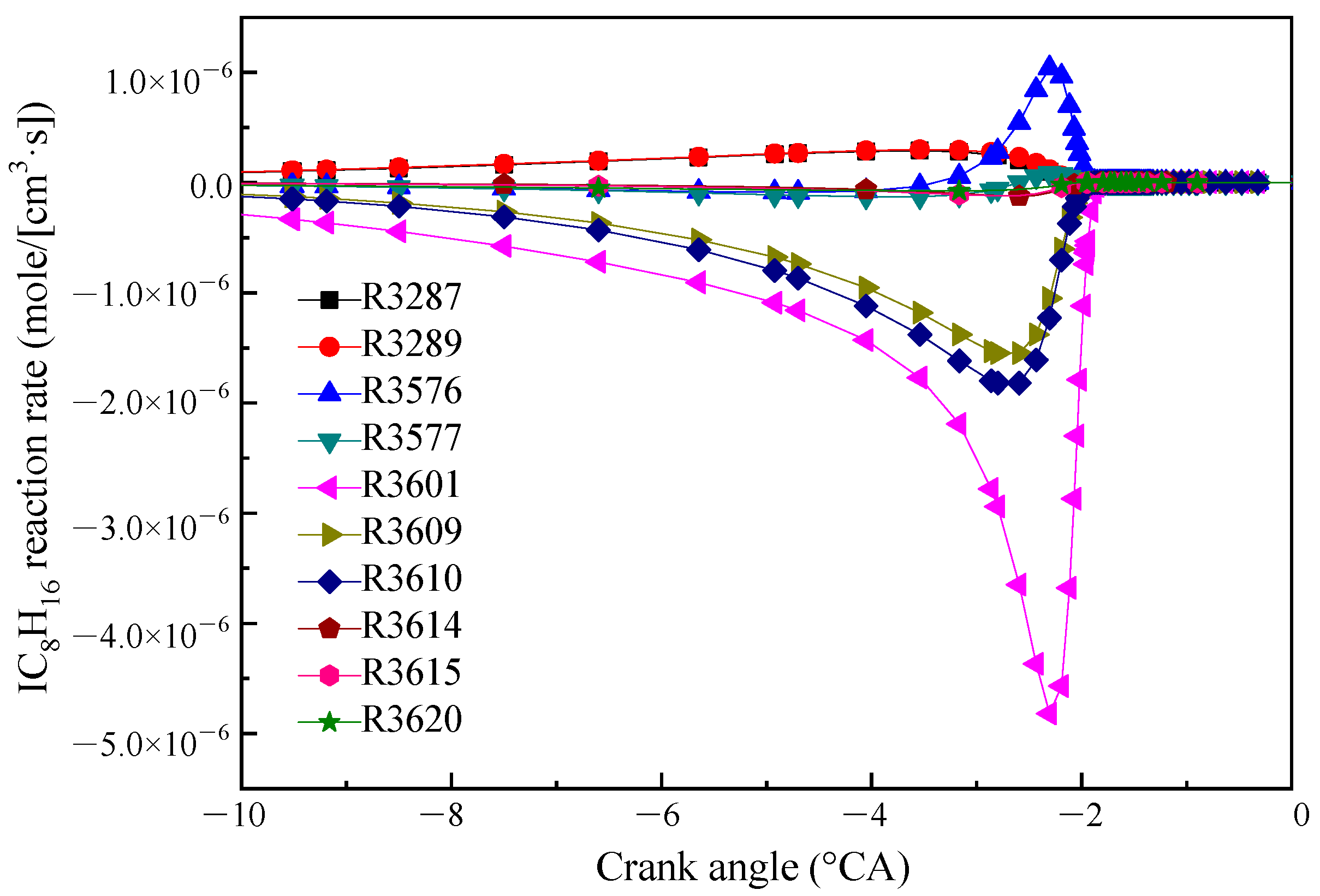
Figure 3.
Reaction rates of the main reactions of the three products YC7H13−Y2 (a), JC8H15−B (b) and IC8H15−A (c).
Figure 3.
Reaction rates of the main reactions of the three products YC7H13−Y2 (a), JC8H15−B (b) and IC8H15−A (c).
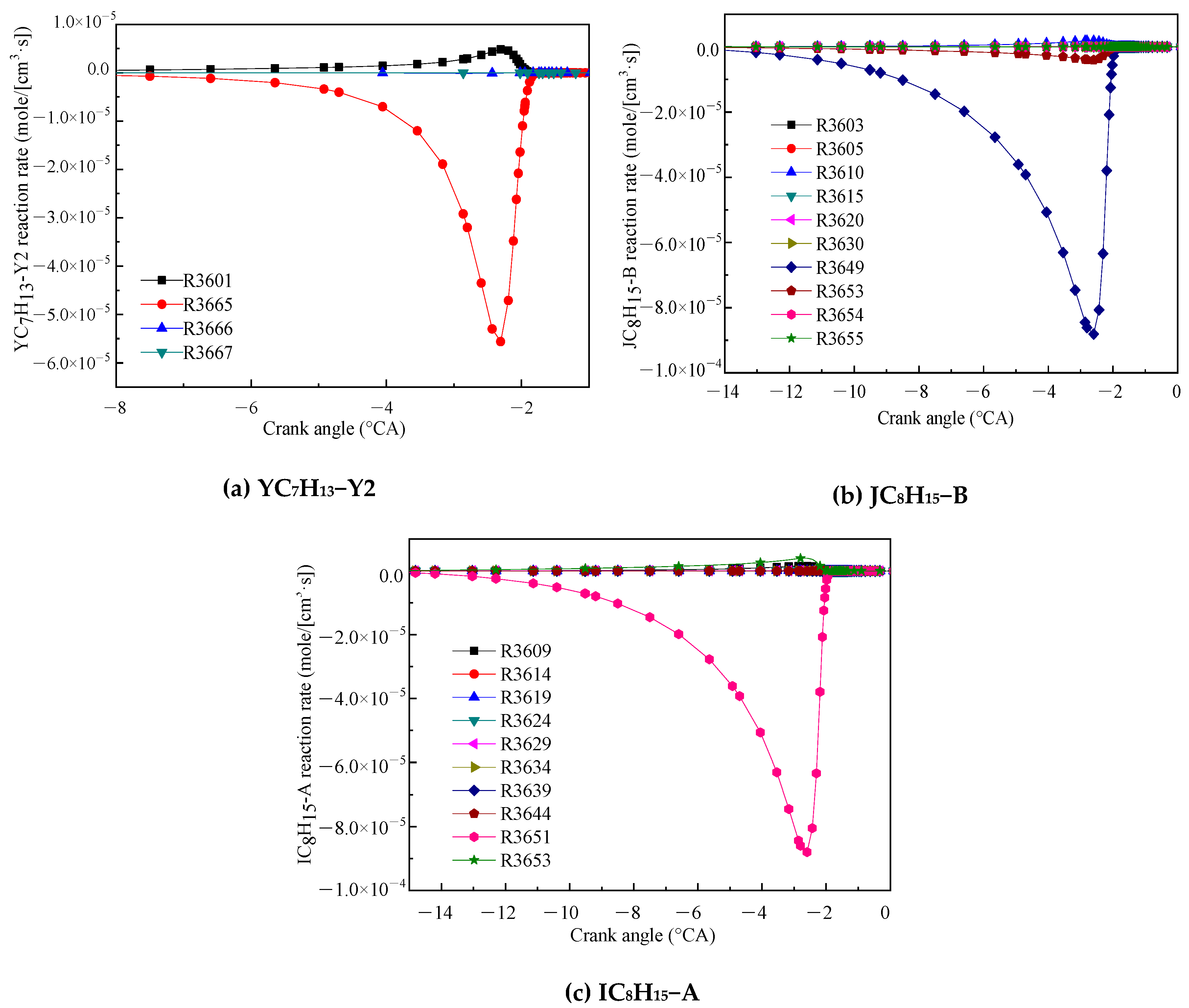
Figure 4.
Reaction path of IC8H16.

Figure 5.
Temperature sensitivity coefficient of engine model simulation for IC8H16. Pressure 1.5 atm, ϕ = 0.25 and 400 and 450 K.
Figure 5.
Temperature sensitivity coefficient of engine model simulation for IC8H16. Pressure 1.5 atm, ϕ = 0.25 and 400 and 450 K.

Figure 6.
Temperature sensitivity coefficient simulated by shock tube model for IC8H16. Pressure 4.0 atm and 1240 and 1500 K.
Figure 6.
Temperature sensitivity coefficient simulated by shock tube model for IC8H16. Pressure 4.0 atm and 1240 and 1500 K.

Figure 7.
Reaction path of NO [24].
Figure 7.
Reaction path of NO [24].

Figure 8.
Main reaction rate of HCN (a) and NCO (b).
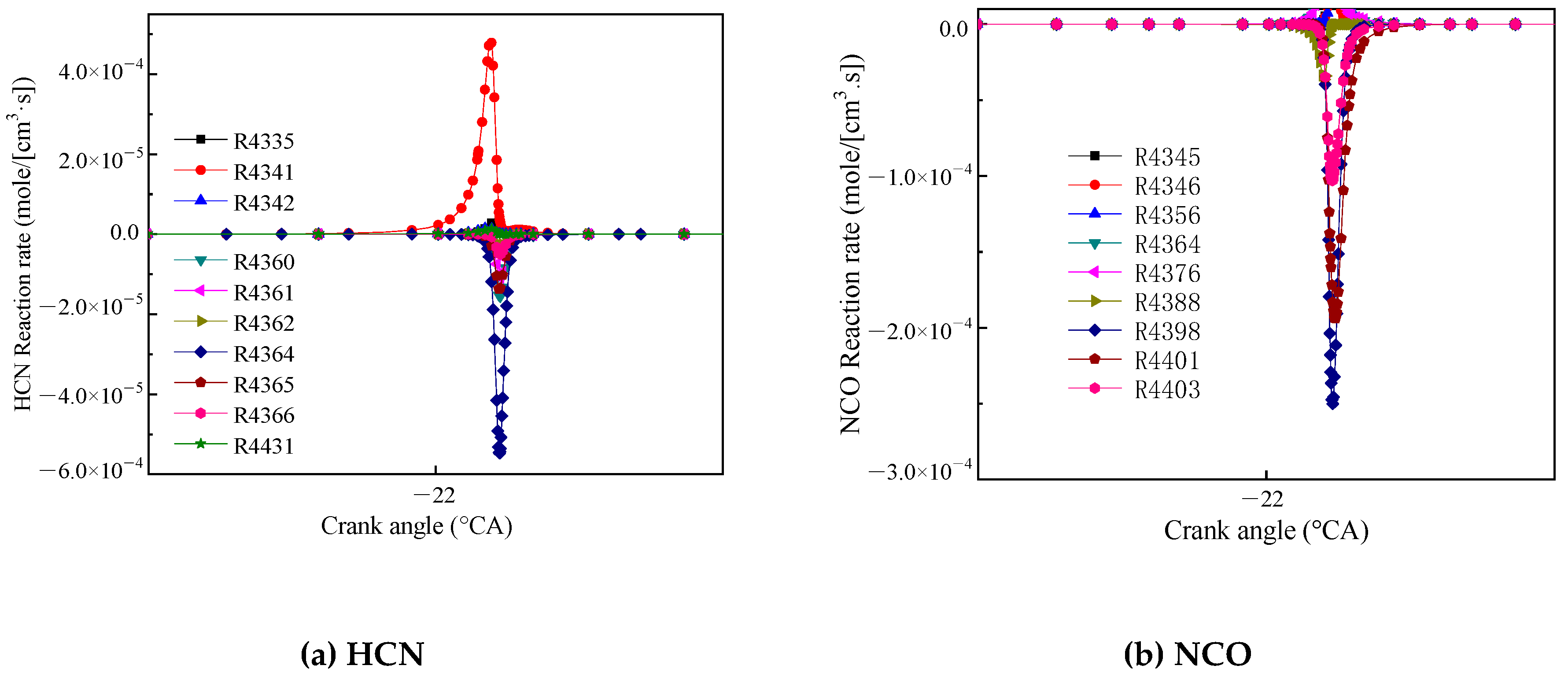
Figure 9.
Main reaction rate of H2CNO2 (a) and CH3NO2 (b).
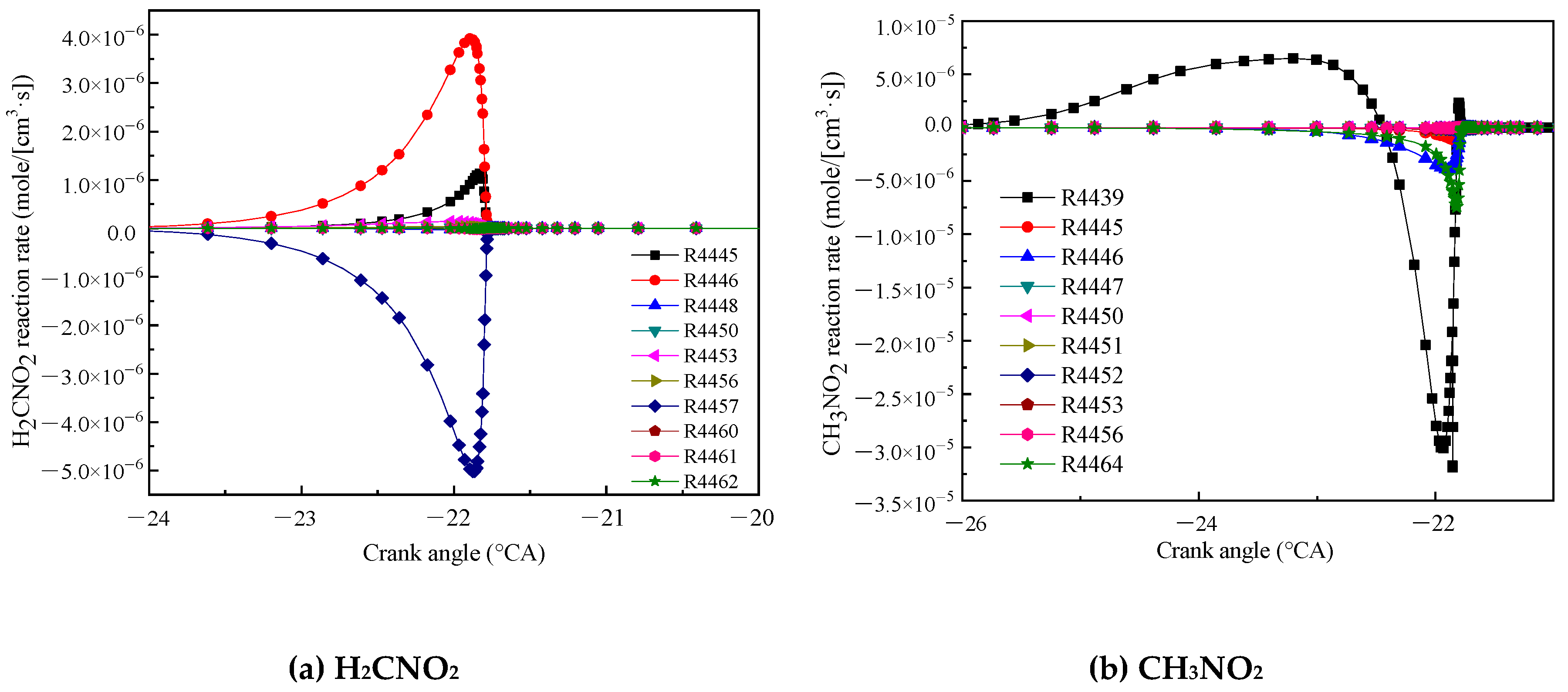
Figure 10.
Comparison of experimental and toluene reference fuel (TRF) submechanism validation results on ignition delay times, (a) Surrogate A, (b) surrogate B.
Figure 10.
Comparison of experimental and toluene reference fuel (TRF) submechanism validation results on ignition delay times, (a) Surrogate A, (b) surrogate B.
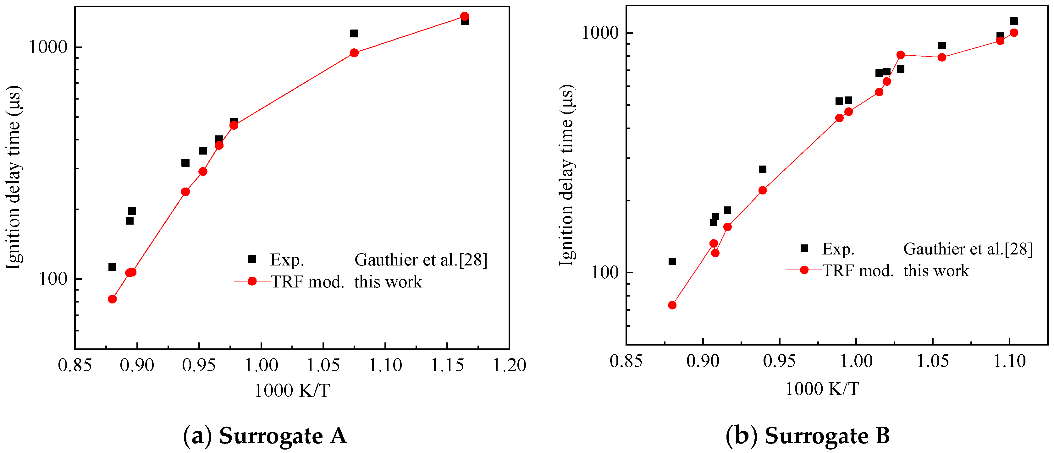
Figure 11.
Comparison of experimental and diisobutylene (DIB) submechanism validation results on ignition delay times, (a) IC8H16, (b) JC8H16 and (c) DIB.
Figure 11.
Comparison of experimental and diisobutylene (DIB) submechanism validation results on ignition delay times, (a) IC8H16, (b) JC8H16 and (c) DIB.
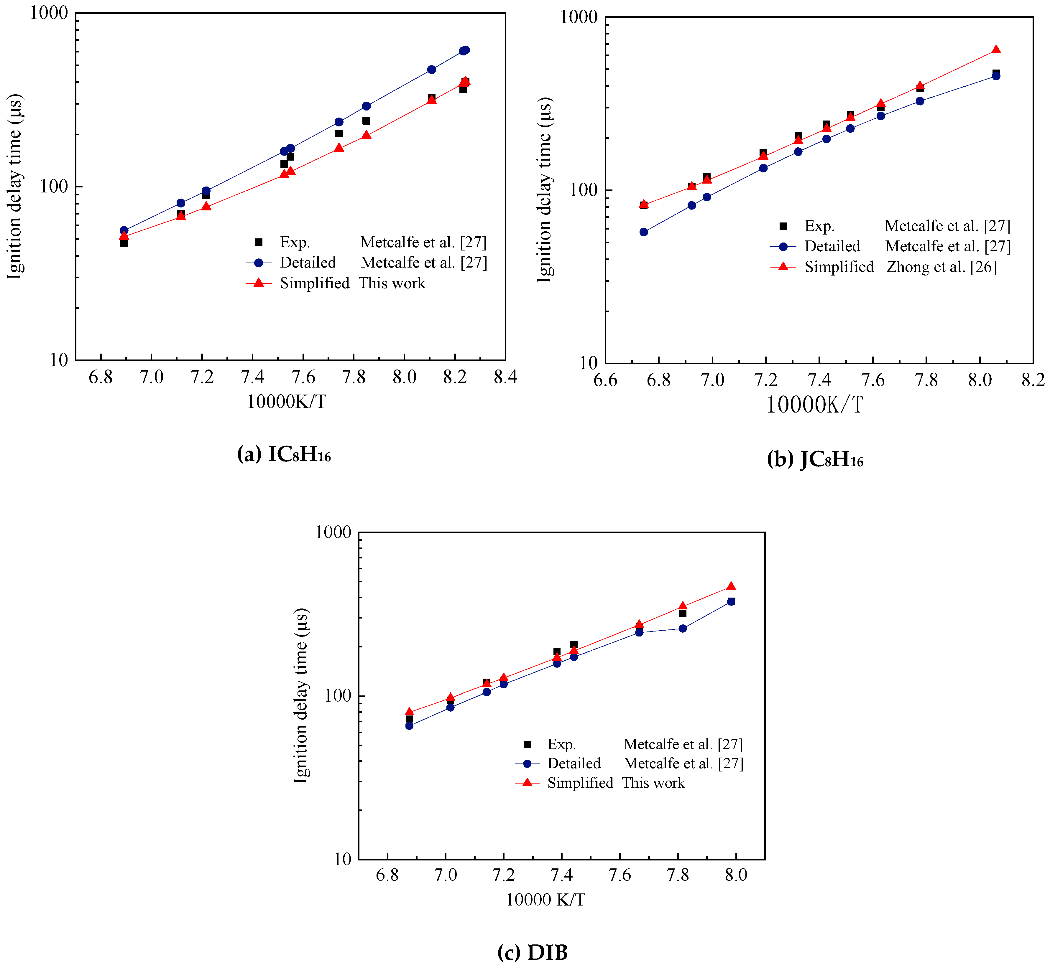
Figure 12.
Comparison of experimental and the five-component gasoline surrogate fuel (TDRF) mechanism validation results on ignition delay times. Pressures of about (a) 10, (b) 30 and (c) 50 bar.
Figure 12.
Comparison of experimental and the five-component gasoline surrogate fuel (TDRF) mechanism validation results on ignition delay times. Pressures of about (a) 10, (b) 30 and (c) 50 bar.
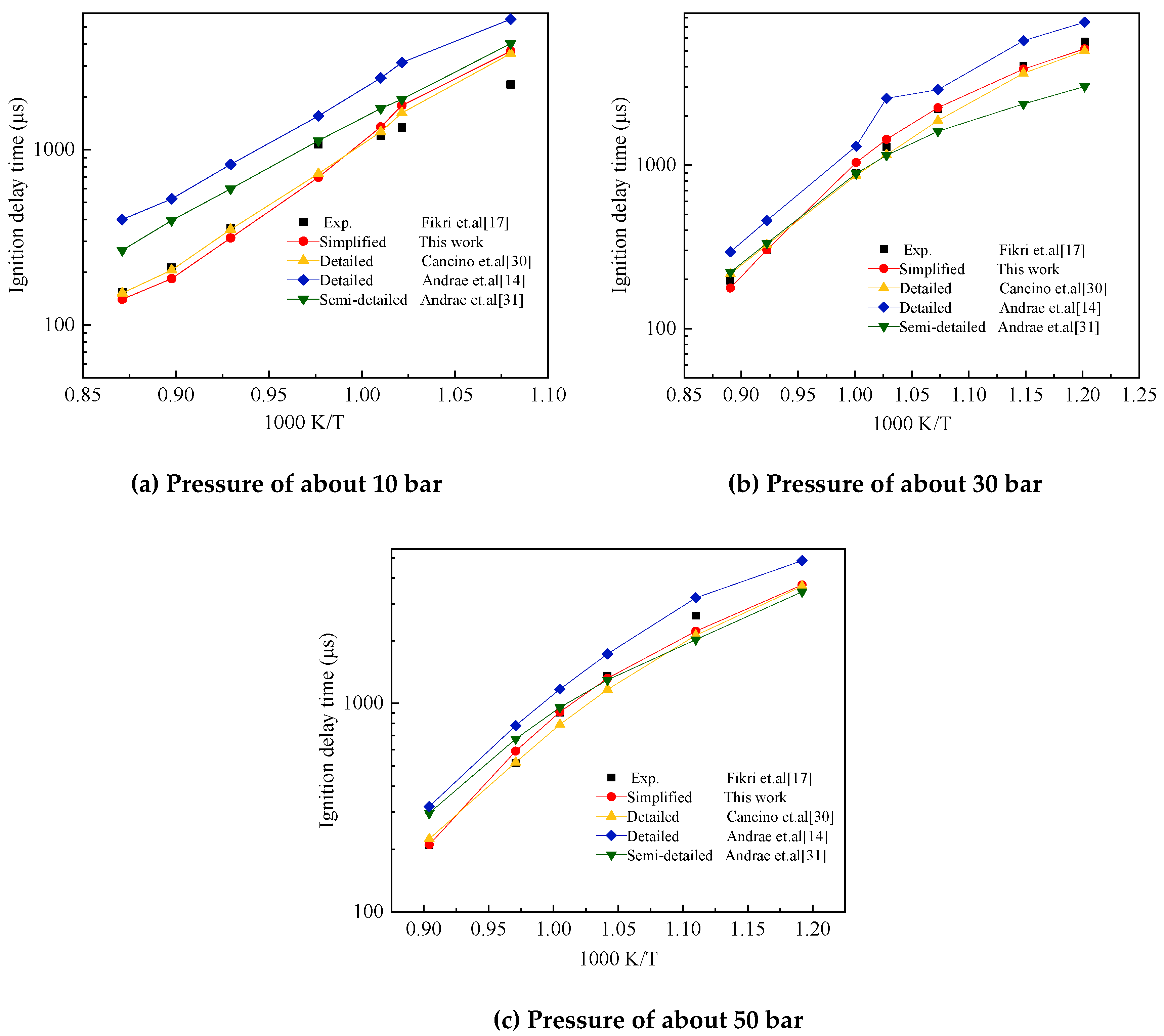
Figure 13.
Comparison of simulated and experimental values of the ignition delay time of Surrogate C with the concentration of NO added.
Figure 13.
Comparison of simulated and experimental values of the ignition delay time of Surrogate C with the concentration of NO added.
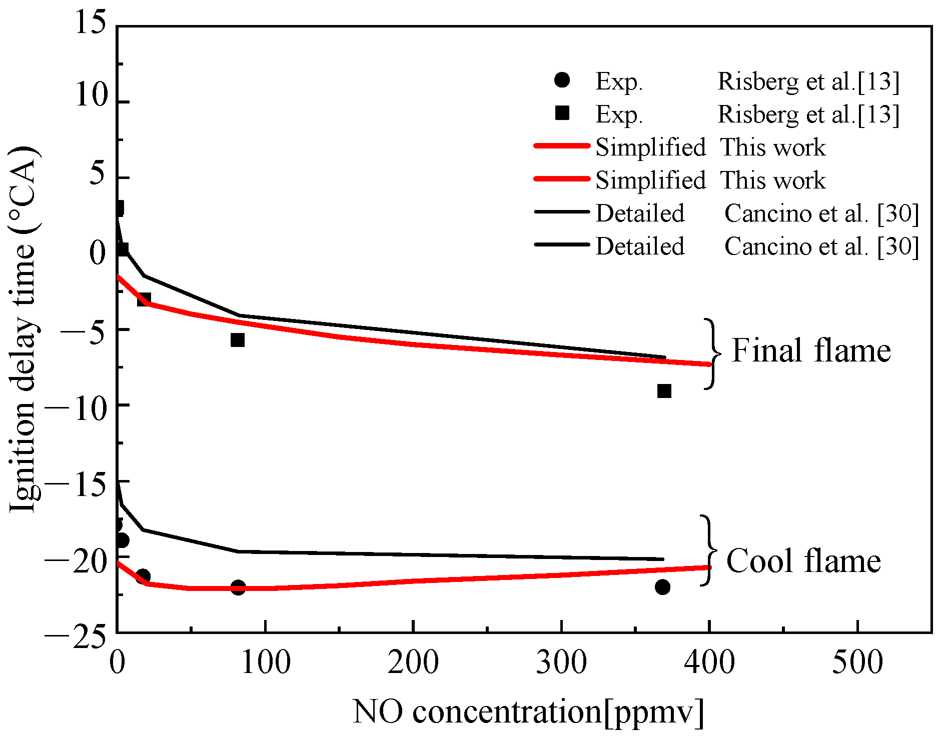
Figure 14.
Comparison of simulated and experimental values of the ignition delay time of Surrogate D with the concentration of NO added. (a) Condition 1, ϕ = 0.25, 4 atm and 600 K; (b) Condition 2, ϕ = 0.25, 2 atm and 800 K.
Figure 14.
Comparison of simulated and experimental values of the ignition delay time of Surrogate D with the concentration of NO added. (a) Condition 1, ϕ = 0.25, 4 atm and 600 K; (b) Condition 2, ϕ = 0.25, 2 atm and 800 K.
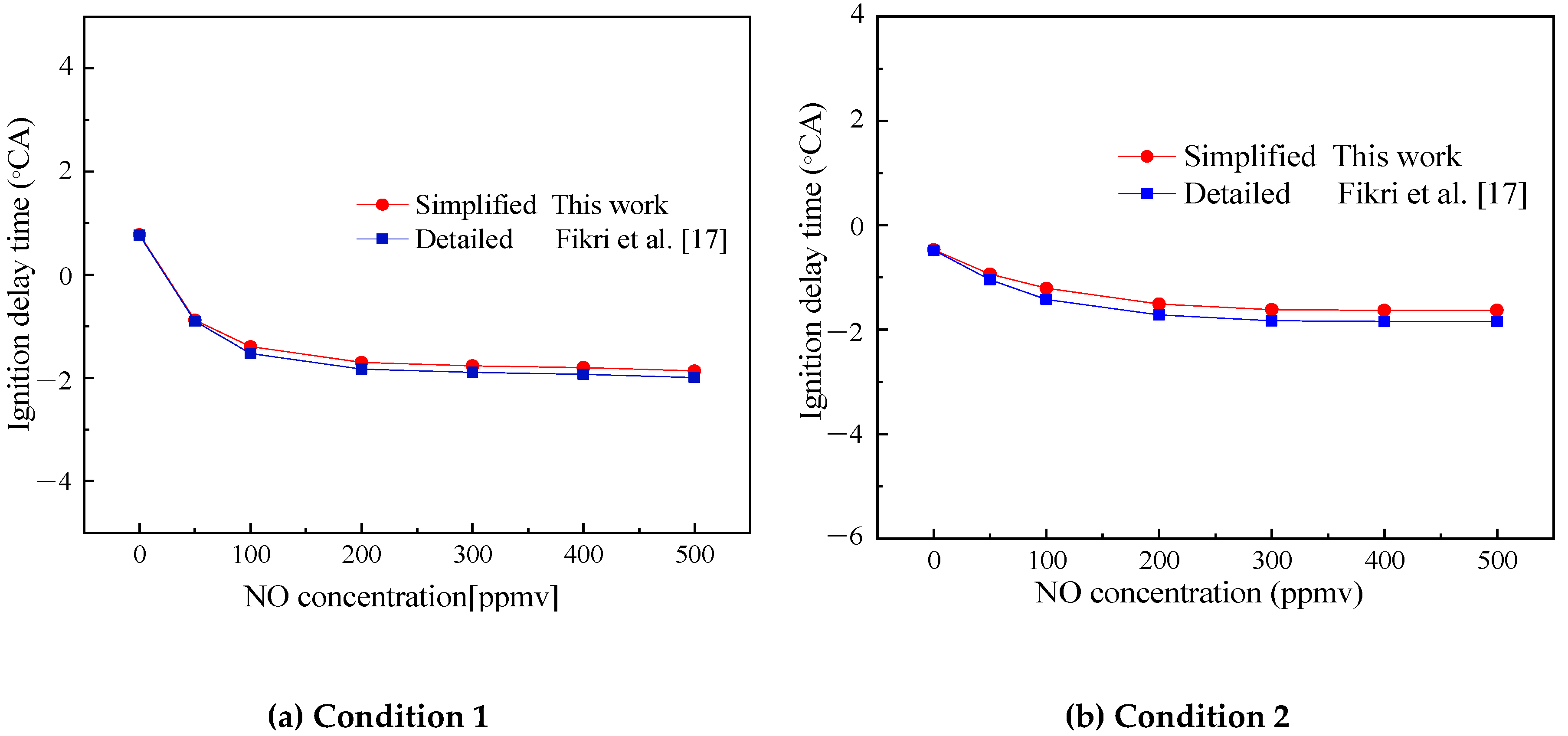
Figure 15.
The solution flow chart of zero-dimensional simulation software.


Table 1.
Main engine parameters.
| Index Item | Value |
|---|---|
| Compression ratio | 17.5 |
| Bore (mm) | 112 |
| Stroke (mm) | 132 |
| Displacement (cm3) | 1300 |
| Speed (rpm) | 1400 |
| Crankshaft radius ratio | 3.714 |
| Temperature (K) | 400 |
| Pressure (atm) | 1.5 |
| Intake valve closing time (°CA) | 38.5 |
Table 2.
Volume ratios of various components of several gasoline surrogate fuels.
| Fuel | Isooctane | Toluene | n-heptane | Diisobutylene | Ref. |
|---|---|---|---|---|---|
| Surrogate A | 63% | 20% | 17% | - | [28] |
| Surrogate B | 69% | 14% | 17% | - | [28] |
| Surrogate C | 13.7% | 34.8% | 51.5% | - | [29] |
| Surrogate D | 20% | 45% | 25% | 10% | [17] |
Table 3.
Mole fractions of 2,4,4-trimethyl-1-pentene and 2,4,4-trimethyl-2-pentene (balance is argon) [27].
Table 3.
Mole fractions of 2,4,4-trimethyl-1-pentene and 2,4,4-trimethyl-2-pentene (balance is argon) [27].
| Fuel | JC8H18 | IC8H16 | O2 | Ar |
|---|---|---|---|---|
| Fuel1 | - | 0.75% | 18% | 81.25% |
| Fuel2 | 0.75% | - | 18% | 81.25% |
| Fuel3 | 0.56% | 0.19% | 18% | 81.25% |
© 2020 by the authors. Licensee MDPI, Basel, Switzerland. This article is an open access article distributed under the terms and conditions of the Creative Commons Attribution (CC BY) license (http://creativecommons.org/licenses/by/4.0/).
Share and Cite
MDPI and ACS Style
Yang, C.; Zheng, Z. Chemical Kinetic Model of Multicomponent Gasoline Surrogate Fuel with Nitric Oxide in HCCI Combustion. Molecules 2020, 25, 2273. https://doi.org/10.3390/molecules25102273
AMA Style
Yang C, Zheng Z. Chemical Kinetic Model of Multicomponent Gasoline Surrogate Fuel with Nitric Oxide in HCCI Combustion. Molecules. 2020; 25(10):2273. https://doi.org/10.3390/molecules25102273
Chicago/Turabian StyleYang, Chao, and Zhaolei Zheng. 2020. "Chemical Kinetic Model of Multicomponent Gasoline Surrogate Fuel with Nitric Oxide in HCCI Combustion" Molecules 25, no. 10: 2273. https://doi.org/10.3390/molecules25102273