
Syntheses and Characterization of Novel Perovskite-Type LaScO3-Based Lithium Ionic Conductors


1
All-Solid-State Battery Unit, Institute of Innovation Research, Tokyo Institute of Technology, 4259 Nagatsuta, Midori-ku, Yokohama 226-8502, Japan
2
Department of Chemical Science and Engineering, School of Materials and Chemical Technology, Tokyo Institute of Technology, 4259 Nagatsuta, Midori-ku, Yokohama 226-8502, Japan
3
Precursory Research for Embryonic Science and Technology (PRESTO), Japan Science and Technology Agency (JST), 4-1-8 Honcho, Kawaguchi-shi, Saitama 332-0012, Japan
*
Author to whom correspondence should be addressed.
Molecules 2021, 26(2), 299; https://doi.org/10.3390/molecules26020299
Submission received: 14 December 2020
/
Revised: 1 January 2021
/
Accepted: 6 January 2021
/
Published: 8 January 2021
(This article belongs to the Special Issue A Themed Issue Dedicated to Professor John B. Goodenough on the Occasion of His 100th Birthday Anniversary)
Abstract
:Perovskite-type lithium ionic conductors were explored in the (LixLa1−x/3)ScO3 system following their syntheses via a high-pressure solid-state reaction. Phase identification indicated that a solid solution with a perovskite-type structure was formed in the range 0 ≤ x < 0.6. When x = 0.45, (Li0.45La0.85)ScO3 exhibited the highest ionic conductivity and a low activation energy. Increasing the loading of lithium as an ionic diffusion carrier expanded the unit cell volume and contributed to the higher ionic conductivity and lower activation energy. Cations with higher oxidation numbers were introduced into the A/B sites to improve the ionic conductivity. Ce4+ and Zr4+ or Nb5+ dopants partially substituted the A-site (La/Li) and B-site Sc, respectively. Although B-site doping produced a lower ionic conductivity, A-site Ce4+ doping improved the conductive properties. A perovskite-type single phase was obtained for (Li0.45La0.78Ce0.05)ScO3 upon Ce4+ doping, providing a higher ionic conductivity than (Li0.45La0.85)ScO3. Compositional analysis and crystal-structure refinement of (Li0.45La0.85)ScO3 and (Li0.45La0.78Ce0.05)ScO3 revealed increased lithium contents and expansion of the unit cell upon Ce4+ co-doping. The highest ionic conductivity of 1.1 × 10⁻³ S cm−1 at 623 K was confirmed for (Li0.4Ce0.15La0.67)ScO3, which is more than one order of magnitude higher than that of the (LixLa1−x/3)ScO3 system.
1. Introduction
All-solid-state lithium batteries have recently received considerable attention as safer, stable, compact, and reliable energy storage devices [1,2]. However, suitable lithium-based solid electrolytes are required for their fabrication [3,4,5,6]. In the past few decades, a range of crystalline and amorphous materials have been examined to prepare solid electrolytes [7,8,9], which can be roughly divided into two groups, namely sulfides [1,10,11,12] and oxides [13,14,15,16]. However, many of the sulfide-based compounds are unstable under air and react with the Li metal electrode [17]. In contrast, the oxide-based group is more stable and easily prepared. As a result, the latter is relatively convenient for battery fabrication in a dry air atmosphere [6].
In the oxide group, Li-La-Ti-O perovskite [13,18,19,20,21] is considered a promising candidate for use as a battery electrolyte due to its high ionic conductivity at room temperature (>10−3 S cm−1) [13]. However, high temperatures (>1000 °C) are required for its preparation and it suffers from electrochemical stability issues due to the reduction of the reducible element Ti4+ to Ti3+ during the electrochemical process, which gives rise to undesirable electronic conduction properties and ultimately affects its practical application [20]. Although lithium ionic conductors developed in this perovskite system have mainly been prepared based on the introduction of lithium vacancies at the A-site [13,22], the development of lithium ionic conductors through the introduction of lithium interstitials in the perovskite-type system has generally not been considered.
We herein focus on LaScO3 [23] as a mother structure for solid electrolytes to investigate the novel perovskite system. We previously considered that the B site cation of Sc3+ would be expected to show a higher resistance to electrochemical reduction than Ti4+ [24]. In addition, it was thought that the low valent Li+ cation could partially substitute the high valent La3+ cation, which could result in the generation of structural defects due to charge compensation, with examples including lithium-ion interstitials that may act as ion carriers for ion diffusion. Therefore, we herein report the development of lithium ionic conductors in the LaScO3-based perovskite system. Initially, different ratios of lithium are introduced into LaScO3 according to the chemical formula (LixLa1−x/3)ScO3, and their ionic conductivities are evaluated. To improve the ionic conductivity of (LixLa1−x/3)ScO3, further modification is carried out by introducing additional structural defects. As the dopant, Ce4+ and Zr4+ or Nb5+ are selected to partially substitute the A- or B- sites of (LixLa1−x/3)ScO3, and perovskite-type lithium-excess lithium ionic conductors are developed in a step-by-step manner. Finally, the composition exhibiting the highest conductivity is identified in the prepared LaScO3 perovskite-based materials.
2. Results and Discussion
2.1. Syntheses and Ionic Conductivities of (LixLa1−x/3)ScO3
The X-ray diffraction (XRD) patterns of (LixLa1−x/3)ScO3 (x = 0–0.60) are shown in Figure 1a,b. The diffraction peaks of the main phase were identified to correspond to the orthorhombic Pnma LaScO3 phase [25]. For the composition where x = 0.6, additional peaks attributed to the impurity (LiScO2) phase were also observed, indicating that the solid solution limit with the LaScO3 structure is x < 0.6. The peak corresponding to the 111 diffraction peak at ~24.5° did not show a clear shift upon increasing the x value (i.e., the Li+ content), although the lattice volume increased slightly (Figure 1c). This indicates that a solid solution formed through lithium doping in the x range of 0.15–0.45. The absence of a significant diffraction peak shifts may be attributed to the introduced lithium ions located at the interstitial positions, which are not sufficient to affect the lattice change. The total content of La and Li at A-site exceeds 1 when x > 0, which indicates that a portion of the lithium ions may be located at the interstitial sites in addition to the A-sites within the structure of LaScO3. These results clearly indicate that lithium-excess perovskite-type materials were successfully formed via this high-pressure synthesis route.
To determine the ionic conductivities of the samples, alternating current (a.c.) impedance measurements were conducted. The total resistance, R, was determined by calculating the intercept value of the semicircular plot with the x-axis. The ionic conductivities were calculated using σ = d/(R × A), where R is the resistance, d is the thickness, and A is the area of the pellet. It should be noted that the a.c. impedance could not be measured for the samples at temperatures < 523 K. Therefore, to compare these ionic conductivities with the actual measured experimental data, the ionic conductivity obtained at the intermediate temperature (623 K) of the test temperature interval was chosen. Figure 2a,b show the typical complex impedance spectra of all sintered compounds at 623 K. These spectra are composed of a semicircle at higher frequencies and a spike at lower frequencies, which correspond to the contributions of the bulk/grain boundary and electrode resistances, respectively. A semicircle with a capacitance value on the order of 10−11 F indicates a total resistance that consists of a mixed contribution (sum of the bulk and grain boundaries). Since the component separation for the bulk and the grain boundary resistance could not be obtained, the total conductivity was calculated from the semicircle as a total resistance.
Figure 2c shows the temperature dependences of the conductivities, while Figure 2d displays the conductivity at 623 K as a function of the composition (x). Table 1 summarizes the ionic conductivities measured at 623 K and the activation energies Ea for the compounds. As indicated, the conductivity continuously increased upon increasing x from 0 to 0.45, and then slightly decreased where x > 0.45. The highest conductivity was observed for the composition with x = 0.45, yielding a value of 4.2 × 10⁻⁵ S cm−1 at 623 K with a low activation energy of 61 kJ mol−1. The decrease in conductivity for the sample where x = 0.60 was likely due to the formation of the impurity phase LiScO2, which exhibits a relatively low ionic conductivity at the same temperature (~10−9 S cm−1 at 623 K) [26]. As the sample where x = 0.45 exhibits the highest ionic conductivity, (Li0.45La0.85)ScO3 was determined to be the optimal initial composition for examining the co-doping systems containing Ce4+, Zr4+, and Nb5+.
2.2. Syntheses and Ionic Conductivities of (LixLa1−x/3)ScO3 co-doped with Ce4+, Zr4+, and Nb5+
For the A-site doping system, two material search directions were examined. The first was La3+ substitution by Ce4+ with fixing of the lithium composition according to the formula (LixLa0.87−4y/3Cey)ScO3, where x = 0.35 or 0.40. The XRD patterns of the obtained samples are shown in Figure 3. Although the LaScO3 phase accounted for the main diffraction peaks, an additional peak derived from the CeO2 impurity was observed at ~28°. The intensity of this peak increased upon increasing the y value (i.e., the amount of Ce doping), while the lattice parameters increased slightly at the same time, as shown in Figure 3c. These results indicate that compositional and/or structural changes occurred depending on the y value, although the mono-phasic perovskite-type solid solution was not obtained.
The second direction of A-site doping was conducted using a fixed Ce content. In this case, charge neutrality was maintained using the La:Li ratio, giving (LixLa0.933−x/3Cey)ScO3, where y = 0.05 was the target composition. The XRD patterns of the obtained products are shown in Figure 4. The sample of (Li0.45La0.78Ce0.05)ScO3 where x = 0.45 exhibited the mono-phasic characteristic of the LaScO3 perovskite, while other compositions showed impurity formation. Even in this case, the small changes in the lattice parameters, which indicate compositional and/or structural changes, were confirmed (Figure 4c).
B-site doping using Zr4+ or Nb5+ was subsequently examined according to the formulae (Li0.45La0.85−z/3)(Sc1−zZrz)O3 and (Li0.45La0.85−2z/3)(Sc1−zNbz)O3. As shown in Figures S1 and S2, evident impurity (LiLaO2) formation was confirmed even with a small amount of doping (z = 0.05) for both dopants. Therefore, B-site doping reduces the lithium content in the perovskite-phase due to part of the lithium source being consumed by the impurity. As indicated in Table 2, where the obtained phases of all doping systems are summarized, the synthetic conditions employed herein did not result in a wide range of single-phase solid solutions upon A- or B- site co-doping into the (Li, La)ScO3 system. As a result, (Li0.45La0.78Ce0.05)ScO3 was found to be the singular example of a pure LaScO3-type phase considering all examined compositions.
All the co-doped samples were then subjected to a.c. impedance measurements; Figure 5a shows the typical a.c. complex impedance spectra of the sample with the nominal composition (Li0.40La0.67Ce0.15)ScO3 (x = 0.4, y = 0.15) recorded at a range of temperatures. The conductivities of the samples were calculated following the same manner as that employed for the non-doped (LixLa1−x/3)ScO3 system. Thus, Figure 5b presents the Arrhenius plots showing the effect of temperature on the conductivity for the representative samples of (LixLa1−x/3−4y/3Cey)ScO3. Since it was not possible to measure the a.c. impedance for every sample at 373 K, the representative conductivities at a higher temperature of 623 K were examined for comparison; the representative conductivities at 623 K and the activation energies for the co-doped samples are summarized in Table 2.
For the Ce4+ co-doped system, a number of compositions were found to exhibit higher conductivities than the (LixLa1−x/3)ScO3 system. For example, (Li0.45La0.78Ce0.05)ScO3, which shows single-phase characteristics, presented a relatively high ionic conductivity of 1.9 × 10⁻⁴ S cm−1 at 623 K. This value is nearly five times higher than that of (Li0.45La0.85)ScO3 at the same temperature. The highest ionic conductivity (i.e., 1.1 × 10⁻³ S cm−1 at 623 K) was obtained for the Ce4+ co-doped (Li0.4La0.67Ce0.15)ScO3, even though it contains an impurity. As noted above, a.c. impedance data could be obtained for all the Ce4+ co-doped samples at a temperature of 373 K, and below 523 K, it was also not possible to obtain these data for (LixLa1−x/3)ScO3, which demonstrates that these Ce4+ co-doped samples have a higher ionic conductivity than that of (LixLa1−x/3)ScO3. In contrast, the activation energy was increased upon Ce4+ co-doping (e.g., 75.2 kJ mol−1 for (Li0.4La0.67Ce0.15)ScO3). The enhancement in the ionic conductivity at the same temperature could, therefore, originate from the increase in the pre-exponential factor (σ0) in the Arrhenius equation: σT = σ0exp(−Ea/kT) [5,27]. Since σ0 is related to the intrinsic number of carriers and defects, Ce4+ co-doping may increase the number of charge carriers, which in turn contributes to ion migration.
The temperature dependences of the conductivities for the (Li0.45La0.85−z/3)(Sc1−zZrz)O3, (Li0.45La0.83−1.33n)(Sc0.95Zr0.05)O3, and (Li0.45La0.85−2z/3)(Sc1−zNbz)O3 samples are shown in Figure S3 (Supporting Information). More specifically, no improvement in the conductivity was observed for the Zr4+ and Nb5+ co-doped systems, and relatively high activation energies were confirmed. The lack of an increase in the ionic conductivity may be due to impurities that consume part of the lithium source in the co-doped samples, thereby decreasing the content of mobile lithium ions. The increase observed for the (LixLa1−x/3)ScO3 system was achieved by A-site Ce4+ co-doping, while the presence of M at the B-site was found to have no effect on the conductivity.
To investigate the electronic contribution to the total conductivity, direct current (d.c.) potentiostatic polarization measurements were performed for (Li0.4La0.67Ce0.15)ScO3, which exhibited the highest conductivity of the examined samples. The steady-state current at specific constant voltages of the symmetrical cell Au|(Li0.4La0.67Ce0.15)ScO3|Au was evaluated by varying the applied voltage from 0.5 to 1.2 V at 623 K (Figure S4); a rapid current decay was observed shortly following a voltage application. From the slope of the I vs. V plot, the electronic conductivity of (Li0.4La0.67Ce0.15)ScO3 was determined to be 7.6 × 10⁻⁷ S cm−1, indicating that electron transport is negligible in (Li0.4La0.67Ce0.15)ScO3 because the calculated value is three orders of magnitude lower than the total conductivity estimated by the a.c. impedance measurements. The conductivity observed for the Ce4+-doped (Li0.4La0.67Ce0.15)ScO3 was therefore attributed mainly to lithium ion diffusion.
These results therefore indicated that a small amount of Ce4+ co-doping enhanced the ionic conductivity. However, the critical factors involved in determining the observed high ionic conductivities remained unclear, and so crystal structure analysis and chemical composition analysis were subsequently carried out.
2.3. Crystal Structure Analysis
(Li0.45La0.85)ScO3 (x = 0.45) and (Li0.45La0.78Ce0.05)ScO3 (x = 0.45, y = 0.05) were taken as representative highly-conductive samples for the doped and co-doped systems, respectively. These samples were also found to show single-phase characteristics, as discussed previously in the context of XRD phase identification. The crystal structures of these samples were then determined by the Rietveld analysis of synchrotron X-ray diffraction data obtained at 298 K. An orthorhombic perovskite-type structural (LaScO3) [25] with Pnma symmetry was applied as an initial model for analysis. The atomic positions for the structure refinement models were as follows: La at the 4c sites, Sc at the 4a sites, O at the 4a and 8d sites.
During the structural refinement, some Li+ was assumed to be present in the A-sites (La3+), and the occupancy factor of the normal-site lithium (A-site) was constrained as 1–g(La) for both samples. The lithium present at the interstitial sites was not refined since X-rays are not sensitive to the light element lithium. The lattice constants, atomic isotropic displacement parameters (Biso), fractional atomic coordinates, atomic occupancies, background parameters, ratio, zero-shift, and profile parameters were then refined. It is worth mentioning that the occupancy of Ce4+ was not considered as a refinement parameter because it possesses the same number of electrons as La3+, which prevents its identification by X-ray analysis. Therefore, the composition of La and Ce in (Li0.45La0.78Ce0.05)ScO3 was estimated by the combination of the La amount obtained by the Rietveld refinement and the La/Ce ratio obtained from inductively coupled plasma atomic emission spectroscopy (ICP-AES) analysis (see Table S1, Supporting Information).
Figure 6 shows the Rietveld refinement patterns, which are also presented in Table 3 and Table 4. All diffraction peaks of the two samples were assigned to the orthorhombic perovskite structure. The obtained reliability factors (S and Rwp) confirmed that the proposed structural model for the diffraction data was reasonable.
The refined composition of (Li0.45La0.85)ScO3 was calculated to be Li0.062La0.938ScO3. Subsequently, the interstitial lithium, which cannot be detected by Rietveld analysis, was considered to satisfy the charge neutrality in the sample. Thus, the composition of (Li0.45La0.85)ScO3 was determined to be Li0.186La0.938ScO3, and this value is comparable to that obtained by ICP-AES (Table S1). These analyses revealed that the practical amount of lithium is less than half of the nominal composition of (Li0.45La0.85)ScO3, which was attributed to the reaction of lithium reaction with the platinum capsule during the synthetic procedure [28].
The composition of the Ce4+ co-doped sample was also determined using the above process. From the Rietveld analysis, Li0.1788La0.8212ScO3 was obtained, whereby the La composition was divided into La and Ce using the La/Ce ratio obtained from the ICP-AES results. Considering the charge neutrality, the composition of Li0.493La0.777Ce0.044ScO3 was determined for the co-doped (Li0.45La0.78Ce0.05)ScO3. This value is comparable to both the nominal and ICP-AES results (Table S1).
The significant difference in the lithium amount between the doped and co-doped samples was clarified based on structural and compositional analysis results. More specifically, only 41% of the lithium present in the nominal composition was incorporated into the doped case sample.
In contrast, a nearly nominal composition was confirmed in the Ce4+ co-doped case. Therefore, the observed enhancement in the ionic conductivity upon co-doping was attributed mainly to the abundant lithium (carrier) number in the crystal structure despite a low doping level of 0.05. This assumption is consistent with the change in activation energy observed upon co-doping, which indicated an increase in the number of charge carriers.
The lattice parameters of the compound (Li0.45La0.85)ScO3 were determined to be a = 5.67921(5), b = 5.79488(4), c = 8.09558(6) Å, and V = 266.4281(36) Å3, while those of (Li0.45La0.78Ce0.05)ScO3 were a = 5.68088(6) Å, b = 5.79624(6) Å, c = 8.09803(9) Å, and V = 266.6500(48) Å3. Compared with LaScO3 [25] (a = 5.6803, b = 5.7907, c = 8.0945 Å, and V = 266.252 Å3), the cell volumes were expanded by +0.07% and +0.15%, respectively. The co-doped (Li0.45La0.78Ce0.05)ScO3 presented a larger unit cell size than (Li0.45La0.85)ScO3. Such an expansion of the cell volume may also contribute to the higher ionic conductivity of (Li0.45La0.78Ce0.05)ScO3, because a larger unit cell size implies larger channels for lithium ion diffusion.
Again, the highest ionic conductivity (i.e., 1.1 × 10⁻³ S cm−1 at 623 K) for the Ce4+ co-doped (Li0.4La0.67Ce0.15)ScO3 was almost two orders of magnitude higher than that of (Li0.45La0.85)ScO3 at the same temperature. The increase in the lithium content as an ionic diffusion carrier, in addition to the expansion of unit cell volume, was thereby considered to contribute synergistically to the higher ionic conductivity of the Ce4+ co-doped system. Determination of the interstitial lithium sites and the La/Ce distribution in the structure through neutron diffraction studies will be conducted in future studies.
3. Materials and Methods
Target materials with the general formula (LixLa1−x/3)ScO3 and those containing Ce4+, Zr4+, and Nb5+ doping were synthesized via a solid-state reaction using the previously reported high-pressure method [28,29]. The starting materials were La2O3 (Kanto Chemical Co., Inc., Tokyo, Japan, ≥99.99% purity), Li2O2 (Kojundo Chemical Laboratory Co. Ltd., Sakado, Saitama Pre., Japan, 99% purity), Sc2O3 (Alfa Aesar, Thermo Fisher Scientific, Waltham, MA, USA, ≥99.9% purity), CeO2 (Wako Pure Chemical Industries, Ltd., Osaka, Japan, ≥99.9% purity), ZrO2 (Wako Pure Chemical Industries, Ltd., ≥99.9% purity), and Nb2O5 (Wako Pure Chemical Industries, Ltd., Osaka, Japan, ≥99.9% purity). Generally, the perovskite system can be synthesized at high temperatures (>1423 K) in an open ambient pressure atmosphere, which often results in lithium evaporation [22]. In this work, the mixed samples were encapsulated in a platinum capsule and subjected to high-pressure synthesis at 2 GPa and 1173–1373 K for 30 min, then quenched by cooling to room temperature. This high-pressure route ensured the incorporation of an accurate amount of Li, in addition to accelerating the reaction.
The synthesized products were characterized by XRD (Rigaku Smart Lab, and Miniflex 300, Rigaku, Tokyo, Japan) using Cu-Kα radiation under an air atmosphere. Diffraction data were collected using a 0.01° step interval and scanning over the range of 10–50°. The lattice constants were determined using Si (SRM640d) as an internal standard for calibration. Synchrotron XRD patterns were recorded at 298 K using the BL02B2 and BL19B2 beamlines at the SPring-8 facility, operating with a wavelength of 0.5 Å. Structural parameters were refined by the Rietveld method using the RIETAN-FP program [30]. Rietveld analyses were conducted to refine the structural parameters using the diffraction data collected at each 0.01° step width over a 2θ range of 10–70°. Chemical analysis was performed by ICP-AES (ICPS-8100, Shimadzu, Tokyo, Japan).
The ionic conductivity of each sample was evaluated by a.c. impedance spectroscopy using a frequency response analyzer (Solartron 1260, AMETEK Scientific Instruments, Berwyn, PA, USA). A gold paste was painted onto each side of the sample as a blocking electrode. The pellets (~3 mm diameter, ~1 mm thickness) were then heated at 300 °C for 30 min under an argon atmosphere to obtain dry samples for carrying out the measurements. The samples were placed under an argon flow, and the measurements were performed between 298 and 673 K at frequencies ranging from 0.1 Hz to 3 MHz with an applied voltage of 20–100 mV.
The electrical conductivity of each sample was measured using the Hebb-Wagner polarization method [31]. The voltage, which was controlled using a potentiostat electrochemical interface (Solartron 1287, AMETEK Scientific Instruments, Berwyn, PA, USA), was applied from 0.1 to 1.2 V. The resulting current obtained due to the electronic contribution was evaluated.
4. Conclusions
Lithium ionic conductors were developed in the (LixLa1−x/3)ScO3 system with a perovskite structure via a high-pressure solid-state reaction. The resulting novel lithium-excess perovskite-type materials exhibited solid solution formation where 0 ≤ x < 0.60. The highest ionic conductivity was observed for (Li0.45La0.85)ScO3, yielding a conductivity of 4.2 × 10⁻⁵ S cm−1 at 623 K with a low activation energy of 61 kJ mol−1. Further improvement in the ionic conductivity of (Li0.45La0.85)ScO3 was examined by introducing aliovalent cations; Ce4+ and Zr4+ or Nb5+ were selected to substitute the A-site La3+ and B-site Sc3+, respectively. Interestingly, improvements in the ionic conductivity of (LixLa1−x/3)ScO3 were achieved only upon Ce4+ co-doping, with the presence of Zr4+ and Nb5+ having no such effect. A mono-phasic sample was obtained for the co-doped (Li0.45La0.78Ce0.05)ScO3 system, which exhibited a higher ionic conductivity compared to (Li0.45La0.85)ScO3. Furthermore, an increase in the activation energy indicated that a rise in the pre-exponential factor (σ0) might contribute to the enhanced conductivity. Compositional analysis and crystal structure refinement revealed the real compositions of (Li0.45La0.85)ScO3 and (Li0.45La0.78Ce0.05)ScO3 to be Li0.186La0.938ScO3 and Li0.493La0.777Ce0.044ScO3, respectively. Our results also indicated that an increase in the lithium amount and expansion of the unit cell volume could contribute to the higher ionic conductivity of (Li0.45La0.78Ce0.05)ScO3 (i.e., 1.9 × 10⁻⁴ S cm−1 at 623 K). Indeed, even a small amount of Ce4+ co-doping had a sufficient effect on the ionic conductivity since it can significantly modify the number of charge carriers in the developed (LixLa1−x/3)ScO3-based materials. Although the ionic conductivity of the obtained materials in this study is not yet very high, these materials are among the rarely studied lithium ion conductors with a perovskite structure consisting of a single-valent metal element at the B-site. Moreover, the lower valency of Sc3+ at B-site suggested that greater number of lithium interstitials could be generated compared to in the case of Ti4+ at the B-site, thereby rendering a higher carrier doping possibility. The obtained materials could be considered for use as template materials to further improve ionic conductivities until they have been further developed to approach a high lithium ion conductivity at low temperatures for practical use. These results are expected to contribute to the development of superior lithium-based solid electrolytes for application in all-solid-state lithium batteries, and the ongoing material search will be expected to expand the varieties of materials available for use in battery applications.
Supplementary Materials
The following are available online. Figure S1: (a) X-ray diffraction patterns, (b) observed shifts of the selected reflections, and (c) variation in the lattice parameters with the composition of (Li0.45La0.85−0.33z)(Sc1−zZrz)O3 (y = 0 and 0.1). Figure S2: (a) X-ray diffraction patterns, (b) observed shifts of the selected reflections, and (c) variation in the lattice parameters with the composition of (Li0.45La0.85−0.67z)(Sc1−zNbz)O3 (z = 0 and 0.1). Figure S3: Temperature dependence of the sample conductivity in (a) (Li0.45La0.85−z/3)(Sc1−zZrz)O3 and (Li0.45La0.83−1.33n)(Sc0.95Zr0.05)O3, and (b) (Li0.45La0.85−2z/3)(Sc1−zNbz)O3. Figure S4: Steady-state current as a function of the applied voltage at 623 K in a dry Ar atmosphere for (Li0.4La0.67Ce0.15)ScO3. Table S1: Chemical compositions of (Li0.45La0.85)ScO3 and (Li0.45La0.78Ce0.05)ScO3.
Author Contributions
Conceptualization, R.K., K.S. and M.H.; validation, G.Z., and K.S.; formal analysis, G.Z. and K.S.; investigation, G.Z. and K.S.; resources, M.H., and R.K.; data curation, G.Z. and K.S.; writing—original draft preparation, G.Z.; writing—review and editing, K.S., M.H., and R.K; visualization, G.Z. and K.S.; supervision, M.H., and R.K.; project administration, M.H., and R.K. All authors have read and agreed to the published version of the manuscript.
Funding
This research was funded by ALCA-SPRING from the Japan Science and Technology Agency (JST) and a Grant-in-Aid for Scientific Research (S) of the Japan Society for the Promotion of Science (JSPS), grant number JPMJAL1301 and 17H06145, respectively.
Institutional Review Board Statement
Not applicable.
Informed Consent Statement
Not available.
Data Availability Statement
The data presented in this study are available in supplementary material.
Acknowledgments
This work was partly supported by ALCA-SPRING from the Japan Science and Technology Agency (JST) Grant Number JPMJAL1301 and a Grant-in-Aid for Scientific Research (S) (No. 17H06145) of the Japan Society for the Promotion of Science (JSPS). The synchrotron radiation experiments were performed at the SPring-8 facility with the approval of the Japan Synchrotron Radiation Research Institute (JASRI) (Proposal nos. 2016B1778 and 2019B1745).
Conflicts of Interest
The authors declare no conflict of interest.
Sample Availability
Not available.
References
- Kamaya, N.; Homma, K.; Yamakawa, Y.; Hirayama, M.; Kanno, R.; Yonemura, M.; Kamiyama, T.; Kato, Y.; Hama, S.; Kawamoto, K.; et al. A lithium superionic conductor. Nat. Mater. 2011, 10, 682–686. [Google Scholar] [CrossRef] [PubMed]
- Kato, Y.; Hori, S.; Saito, T.; Suzuki, K.; Hirayama, M.; Mitsui, A.; Yonemura, M.; Iba, H.; Kanno, R. High-power all-solid-state batteries using sulfide superionic conductors. Nat. Energy 2016, 1, 1–7. [Google Scholar]
- Ma, C.; Chen, K.; Liang, C.; Nan, C.-W.; Ishikawa, R.; Morea, K.; Chi, M. Atomic-scale origin of the large grain-boundary resistance in perovskite Li-ion-conducting solid electrolytes. Energy Environ. Sci. 2014, 7, 1638–1642. [Google Scholar] [CrossRef] [Green Version]
- Cao, C.; Li, Z.-B.; Wang, X.-L.; Zhao, X.-B.; Han, W.-Q. Recent advances in inorganic solid electrolytes for lithium batteries. Front. Energy Res. 2014, 2, 1–10. [Google Scholar]
- Bachman, J.C.; Muy, S.; Grimaud, A.; Chang, H.-H.; Pour, N.; Lux, S.F.; Paschos, O.; Maglia, F.; Lupart, S.; Lamp, P.; et al. Inorganic solid-state electrolytes for lithium batteries: Mechanisms and properties governing ion conduction. Chem. Rev. 2016, 116, 140–162. [Google Scholar] [CrossRef]
- Sun, C.; Liu, J.; Gong, Y.; Wilkinson, D.P.; Zhang, J. Recent advances in all-solid-state rechargeable lithium batteries. Nano Energy 2017, 33, 363–386. [Google Scholar] [CrossRef] [Green Version]
- Van den Broek, J.; Afyon, S.; Rupp, J.L.M. Interface-engineered all-solid-state li-ion batteries based on garnet-type fast Li+ conductors. Adv. Energy Mater. 2016, 6, 1–11. [Google Scholar]
- Li, X.; Liang, J.; Yang, X.; Adair, K.R.; Wang, C.; Zhao, F.; Sun, X. Progress and perspectives on halide lithium conductors for all-solid-state lithium batteries. Energy Environ. Sci. 2020, 13, 1429–1461. [Google Scholar] [CrossRef]
- Zhao, Q.; Stalin, S.; Zhao, C.-Z.; Archer, L.A. Designing solid-state electrolytes for safe, energy-dense batteries. Nat. Rev. Mater. 2020, 1, 229–252. [Google Scholar] [CrossRef]
- Hori, S.; Suzuki, K.; Hirayama, M.; Kato, Y.; Saito, T.; Yonemura, M.; Kanno, R. Synthesis, structure, and ionic conductivity of solid solution, Li10+δM1+δP2-δS12 (M = Si, Sn). Faraday Discuss. 2014, 176, 83–94. [Google Scholar] [CrossRef]
- Inoue, Y.; Suzuki, K.; Matsui, N.; Hirayama, M.; Kanno, R. Synthesis and structure of novel lithium-ion conductor Li7Ge3PS12. J. Solid State Chem. 2017, 246, 334–340. [Google Scholar] [CrossRef]
- Hori, S.; Suzuki, K.; Hirayama, M.; Kato, Y.; Kanno, R. Lithium superionic conductor Li9.42Si1.02P2.1S9.96O2.04 with Li10GeP2S12-type structure in the Li2S–P2S5–SiO2 pseudoternary system: Synthesis, electrochemical properties, and structure–composition relationships. Front. Energy Res. 2016, 4, 1–10. [Google Scholar] [CrossRef]
- Inaguma, Y.; Liquan, C.; Itoh, M.; Nakamura, T. High ionic conductivity in lithium lanthanum titanate. Solid State Commun. 1993, 86, 689–693. [Google Scholar] [CrossRef]
- Hallopeau, L.; Bregiroux, D.; Rousse, G.; Portehault, D.; Stevens, P.; Toussaint, G.; Laberty-Robert, C. Microwave-assisted reactive sintering and lithium ion conductivity of Li1.3Al0.3Ti1.7(PO4)3 solid electrolyte. J. Power Sources 2017, 378, 48–52. [Google Scholar] [CrossRef] [Green Version]
- Kuwano, J.; West, A.R. New Li+ ion conductors in the system, Li4GeO4-Li3VO4. Mater. Res. Bull. 1980, 15, 1661–1667. [Google Scholar] [CrossRef]
- Alpen, U.V.; Bell, M.F.; Wichelhaus, W. Ionic conductivity of Li14Zn(GeO4) (Lisicon). Electrochim. Acta 1978, 23, 1395–1397. [Google Scholar] [CrossRef]
- Wenzel, S.; Randau, S.; Leichtweiß, T.; Weber, D.A.; Sann, J.; Zeier, W.G.; Janek, J. Direct observation of the interfacial instability of the fast ionic conductor Li10GeP2S12 at the lithium metal anode. Chem. Mater. 2016, 28, 2400–2407. [Google Scholar] [CrossRef]
- Itoh, M.; Inaguma, Y.; Jung, W.-H.; Chen, L.; Nakamura, T. High lithium ion conductivity in the perovskite-type compounds. Solid State Ion. 1994, 70, 203–207. [Google Scholar] [CrossRef]
- García-Martin, S.; García-Alvarado, F.; Robertson, A.D.; West, A.R.; Alario-Franco, M.A. Microstructural study of the Li+ ion substituted perovskites Li0.5−3xNd0.5+xTiO3. J. Solid State Chem. 1997, 128, 97–101. [Google Scholar] [CrossRef]
- Birke, P.; Scharner, S.; Huggins, R.A.; Weppner, W. Electrolytic stability limit and rapid lithium insertion in the fast-ion-conducting Li0.29La0.57TiO3 perovskite-type compound. J. Electrochem. Soc. 1997, 144, L167–L169. [Google Scholar] [CrossRef]
- Kawakami, Y.; Ikuta, H.; Wakihara, M. Ionic conduction of lithium for perovskite type compounds, (Li0.05La0.317)1−xSr0.5xNbO3, (Li0.1La0.3)1−xSr0.5xNbO3 and (Li0.25La0.25)1−xM0.5xNbO3 (M = Ca and Sr). J. Solid State Electrochem. 1998, 110, 187–192. [Google Scholar] [CrossRef]
- Stramare, S.; Thangadura, V.; Weppner, W. Lithium lanthanum titanates: A review. Chem. Mater. 2003, 15, 3974–3990. [Google Scholar] [CrossRef]
- Bhalla, A.S.; Guo, R.; Roy, R. The perovskite structure—A review of its role in ceramic science and technology. Mater. Res. Innov. 2000, 4, 3–26. [Google Scholar] [CrossRef]
- Hellstrom, E.E.; Van Gool, W. Li ion conduction in Li2ZrO3, Li4ZrO4, and LiScO2. Solid State Ion. 1981, 2, 59–64. [Google Scholar] [CrossRef]
- Liferovich, R.P.; Mitchell, R.H. A structural study of ternary lanthanide orthoscandate perovskites. J. Solid State Chem. 2004, 177, 2188–2197. [Google Scholar] [CrossRef]
- Zhao, G.; Muhammad, I.; Suzuki, K.; Hirayama, M.; Kanno, R. Synthesis, crystal structure, and the ionic conductivity of new lithium ion conductors, M-doped LiScO2 (M = Zr, Nb, Ta). Mater. Trans. 2016, 57, 1370–1373. [Google Scholar] [CrossRef] [Green Version]
- Muy, S.; Bachman, J.C.; Chang, H.-H.; Giordano, L.; Maglia, F.; Lupart, S.; Lamp, P.; Zeier, W.G.; Shao-Horn, Y. Lithium conductivity and Meyer-Neldel rule in Li3PO4-Li3VO4-Li4GeO4 lithium superionic conductors. Chem. Mater. 2018, 30, 5573–5582. [Google Scholar] [CrossRef]
- Mizuno, Y.; Matsuda, Y.; Suzuki, K.; Yonemura, M.; Hirayama, M.; Kanno, R. Synthesis, crystal structure, and electrochemical properties of Li1.2+xMn0.3Co0.2Ni0.3O2 (x > 0) for lithium-ion battery cathodes. Electrochemistry 2015, 83, 820–823. [Google Scholar] [CrossRef] [Green Version]
- Phraewphiphat, T.; Iqbal, M.; Suzuki, K.; Hirayama, M.; Kanno, R. Synthesis and Lithium-Ion Conductivity of LiSrB2O6F (B = Nb5+, Ta5+) with a Pyrochlore Structure. J. Jpn. Soc. Powder Powder Metall. 2018, 65, 26–33. [Google Scholar] [CrossRef] [Green Version]
- Izumi, F.; Momma, K. Three-dimensional visualization in powder diffraction. Solid State Phenom. 2007, 130, 15–20. [Google Scholar] [CrossRef]
- Neudecker, B.-J.; Weppner, W. Li9SiAlO8: A lithium ion electrolyte for voltages above 5.4 V. J. Electrochem. Soc. 1996, 143, 2198–2203. [Google Scholar] [CrossRef]
Figure 1.
(a,b) X-ray diffraction patterns and (c) dependence of the lattice parameters on the composition of (LixLa1−x/3)ScO3 (x = 0, 0.15, 0.30, 0.45). Lattice parameter data for LaScO3 (x = 0) were taken from the literature [25].
Figure 1.
(a,b) X-ray diffraction patterns and (c) dependence of the lattice parameters on the composition of (LixLa1−x/3)ScO3 (x = 0, 0.15, 0.30, 0.45). Lattice parameter data for LaScO3 (x = 0) were taken from the literature [25].

Figure 2.
(a,b) Impedance plots obtained at 623 K, (c) temperature dependence of the conductivity, and (d) variation in the conductivity at 623 K based on the composition of (LixLa1−x/3)ScO3 (x = 0.15, 0.30, 0.45, 0.60).
Figure 2.
(a,b) Impedance plots obtained at 623 K, (c) temperature dependence of the conductivity, and (d) variation in the conductivity at 623 K based on the composition of (LixLa1−x/3)ScO3 (x = 0.15, 0.30, 0.45, 0.60).
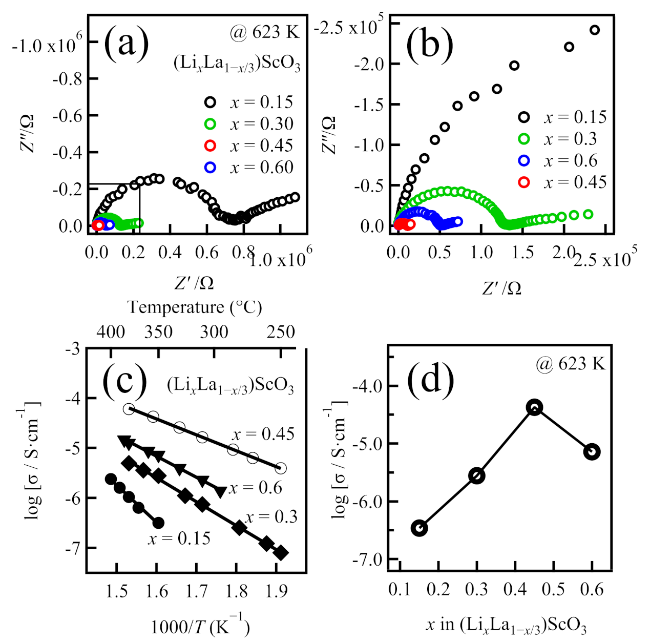
Figure 3.
Variation in (a,b) the X-ray diffraction patterns, and (c) the lattice parameters based on the composition of the as-prepared (Li0.4La0.87−4y/3Cey)ScO3 (y = 0.05, 0.10, 0.15).
Figure 3.
Variation in (a,b) the X-ray diffraction patterns, and (c) the lattice parameters based on the composition of the as-prepared (Li0.4La0.87−4y/3Cey)ScO3 (y = 0.05, 0.10, 0.15).
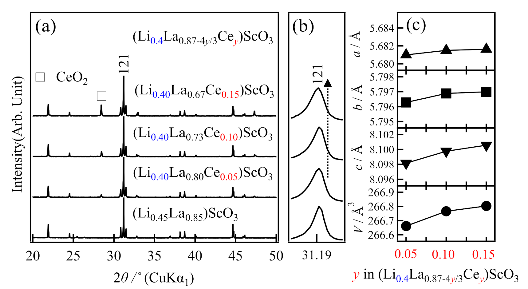
Figure 4.
Variation in (a,b) the X-ray diffraction patterns, and (c) the lattice parameters based on the composition of the as-prepared (LixLa0.933−x/3Ce0.05)ScO3 (x = 0.4, 0.45, and 0.50).
Figure 4.
Variation in (a,b) the X-ray diffraction patterns, and (c) the lattice parameters based on the composition of the as-prepared (LixLa0.933−x/3Ce0.05)ScO3 (x = 0.4, 0.45, and 0.50).
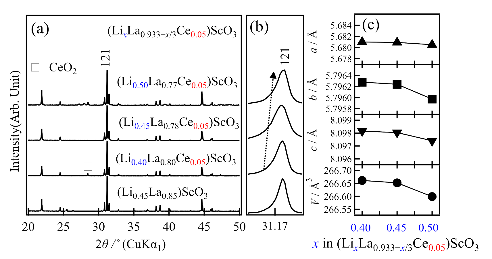
Figure 5.
(a) Impedance plots of the representative co-doped (LixLa1−x/3)ScO3 at various temperatures, and (b) temperature dependence of the conductivity of the representative samples in (LixLa1−x/3−4y/3Cey)ScO3.
Figure 5.
(a) Impedance plots of the representative co-doped (LixLa1−x/3)ScO3 at various temperatures, and (b) temperature dependence of the conductivity of the representative samples in (LixLa1−x/3−4y/3Cey)ScO3.
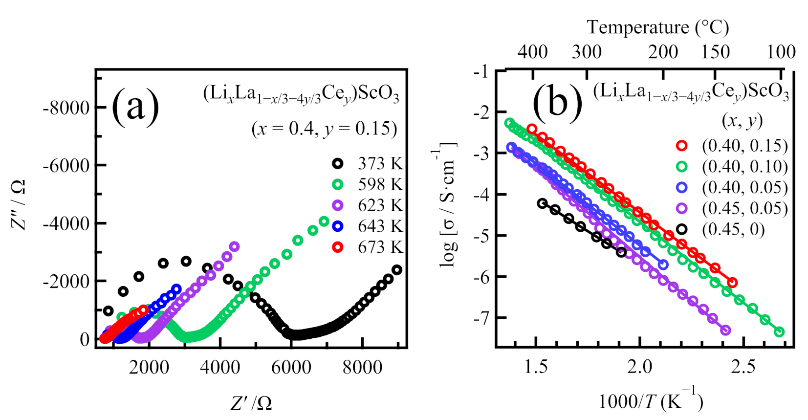
Figure 6.
(Color online) Synchrotron Rietveld refinement patterns for (Li0.45La0.85)ScO3 (a) and (Li0.45La0.78Ce0.05)ScO3 (b) at 298 K. Red: observed intensities; black: calculated intensities; and blue: difference plots. Green vertical markers denote the positions of the Bragg reflections of the space group Pnma (62) (perovskite structure).


Table 1.
Ionic conductivities at 623 K and activation energies of the obtained (LixLa1−x/3)ScO3.
| Formula | Nominal Composition | Identified Phases | σtotal/S cm−1 | Ea/kJ mol−1 |
|---|---|---|---|---|
| (LixLa1−x/3)ScO3 | LaScO3 | LaScO3-type | − | − |
| (Li0.15La0.95)ScO3 | LaScO3-type | 3.4 × 10⁻⁷ | 143.0 ± 6.8 | |
| (Li0.30La0.90)ScO3 | LaScO3-type | 2.8 × 10⁻⁶ | 91.6 ± 1.7 | |
| (Li0.45La0.85)ScO3 | LaScO3-type | 4.2 × 10⁻⁵ | 61.0 ± 0.9 | |
| (Li0.60La0.80)ScO3 | LaScO3-type, LaLiO2 | 7.2 × 10⁻⁶ | 80.7 ± 2.2 |
Table 2.
Dependence of the ionic conductivities at 623 K and the activation energies on the Ce4+, Zr4+, and Nb5+ co-doped (LixLa1−x/3)ScO3 compositions.
Table 2.
Dependence of the ionic conductivities at 623 K and the activation energies on the Ce4+, Zr4+, and Nb5+ co-doped (LixLa1−x/3)ScO3 compositions.
| Chemical Formula | Composition | Identified Phases | σtotal/S cm−1 | Ea/kJ mol−1 |
|---|---|---|---|---|
| (LixLa1−x/3)ScO3 | (Li0.45La0.85)ScO3 | LaScO3-type | 4.2 × 10⁻⁵ | 61.0 ± 0.9 |
| (LixLa1−x/3−4y/3Cey)ScO3 | x = 0.35 (fixed), y = 0.05 (Li0.35La0.82Ce0.05)ScO3 | LaScO3-type, CeO2, unknown | 2.1 × 10⁻⁵ | 88.9 ± 0.7 |
| x = 0.35 (fixed), y = 0.10 (Li0.35La0.75Ce0.10)ScO3 | LaScO3-type, CeO2 | 2.4 × 10⁻⁵ | 87.9 ± 0.3 | |
| x = 0.40 (fixed), y = 0.10 (Li0.40La0.73Ce0.10)ScO3 | LaScO3-type, CeO2 | 8.8 × 10⁻⁴ | 75.5 ± 0.6 | |
| x = 0.40 (fixed), y = 0.15 (Li0.40La0.67Ce0.15)ScO3 | LaScO3-type, CeO2 | 1.1 × 10⁻³ | 75.4 ± 0.1 | |
| x = 0.40, y = 0.05 (fixed) (Li0.50La0.77Ce0.05)ScO3 | LaScO3-type, CeO2 | 5.5 × 10⁻⁵ | 78.2 ± 2.5 | |
| x = 0.45, y = 0.05 (fixed) (Li0.45La0.78Ce0.05)ScO3 | LaScO3-type | 1.9 × 10⁻⁴ | 82.9 ± 2.1 | |
| x = 0.50, y = 0.05 (fixed) (Li0.50La0.72Ce0.10)ScO3 | LaScO3-type, CeO2, unknown | 1.3 × 10⁻⁵ | 86.5 ± 0.3 | |
| (Li0.45La0.85−0.33z)(Sc1−zZrz)O3 | (Li0.45La0.833)(Sc0.95Zr0.05)O3 | LaScO3-type, LiLaO2 | 7.36 × 10⁻⁶ | 77.9 ± 2.0 |
| (Li0.45La0.817)(Sc0.90Zr0.10)O3 | LaScO3-type, LiLaO2 | 8.03× 10⁻⁶ | 75.6 ± 1.8 | |
| (Li0.45La0.85−0.67z)(Sc1−zNbz)O3 | (Li0.45La0.817)(Sc0.95Nb0.05)O3 | LaScO3-type, LiLaO2 | 3.67 × 10⁻⁶ | 81.1 ± 0.9 |
| (Li0.45La0.783)(Sc0.90Nb0.10)O3 | LaScO3-type, LiLaO2 | 9.50 × 10⁻⁶ | 82.0 ± 1.9 |
Table 3.
Crystallographic parameters of the synchrotron diffraction data for (Li0.45La0.85)ScO3 refined by Rietveld analysis.
Table 3.
Crystallographic parameters of the synchrotron diffraction data for (Li0.45La0.85)ScO3 refined by Rietveld analysis.
| Atom | Site | g | x | y | z | Biso/Å2 |
|---|---|---|---|---|---|---|
| La | 4c | 0.938(2) | 0.95637(10) | 0.25 | 0.01062(13) | 0.235(9) |
| Li | 4c | =1–g(La) | =x (La) | =y (La) | =z (La) | =B (La) |
| Sc | 4b | 1.0 | 0.5 | 0 | 0 | 0.908(7) |
| O1 | 4c | 1.0 | 0.53871(1) | 0.25 | 0.90136(4) | 0.788(6) |
| O2 | 8d | 1.0 | 0.29065(7) | 0.94553(6) | 0.70253(7) | 0.848 (3) |
a = 5.67921(5) Å, b = 5.79488(4) Å and c = 8.09558(6) Å, V = 266.4281(36); Rwp = 8.638, S = 1.899, Rb = 6.080, Rf = 4.965.
Table 4.
Crystallographic parameters of the synchrotron diffraction data for (Li0.45La0.78Ce0.05)ScO3 refined by Rietveld analysis
Table 4.
Crystallographic parameters of the synchrotron diffraction data for (Li0.45La0.78Ce0.05)ScO3 refined by Rietveld analysis
| Atom | Site | g | x | y | z | Biso/ Å2 |
|---|---|---|---|---|---|---|
| La | 4c | 0.8212(5) | 0.95622(4) | 0.25 | 0.00892(6) | 0.178(3) |
| Li | 4c | =1–g(La) | =x (La) | =y (La) | =z (La) | =B (La) |
| Sc | 4b | 1.0 | 0.5 | 0 | 0 | 1.209(4) |
| O1 | 4c | 1.0 | 0.53153(4) | 0.25 | 0.90757(5) | 0.699(3) |
| O2 | 8d | 1.0 | 0.2951(6) | 0.9419(3) | 0.70075(3) | 1.825(4) |
a= 5.68088(6) Å, b = 5.79624(6) Å and c = 8.09803(9) Å, V = 266.6500(48); Rwp = 8.850, S = 2.315, Rb = 5.343, Rf = 3.752.
Publisher’s Note: MDPI stays neutral with regard to jurisdictional claims in published maps and institutional affiliations. |
© 2021 by the authors. Licensee MDPI, Basel, Switzerland. This article is an open access article distributed under the terms and conditions of the Creative Commons Attribution (CC BY) license (http://creativecommons.org/licenses/by/4.0/).
Share and Cite
MDPI and ACS Style
Zhao, G.; Suzuki, K.; Hirayama, M.; Kanno, R. Syntheses and Characterization of Novel Perovskite-Type LaScO3-Based Lithium Ionic Conductors. Molecules 2021, 26, 299. https://doi.org/10.3390/molecules26020299
AMA Style
Zhao G, Suzuki K, Hirayama M, Kanno R. Syntheses and Characterization of Novel Perovskite-Type LaScO3-Based Lithium Ionic Conductors. Molecules. 2021; 26(2):299. https://doi.org/10.3390/molecules26020299
Chicago/Turabian StyleZhao, Guowei, Kota Suzuki, Masaaki Hirayama, and Ryoji Kanno. 2021. "Syntheses and Characterization of Novel Perovskite-Type LaScO3-Based Lithium Ionic Conductors" Molecules 26, no. 2: 299. https://doi.org/10.3390/molecules26020299