Graphene Oxide Induced Osteogenesis Quantification by In-Situ 2D-Fluorescence Spectroscopy

 ,
,  and
and
Abstract
:
1. Introduction
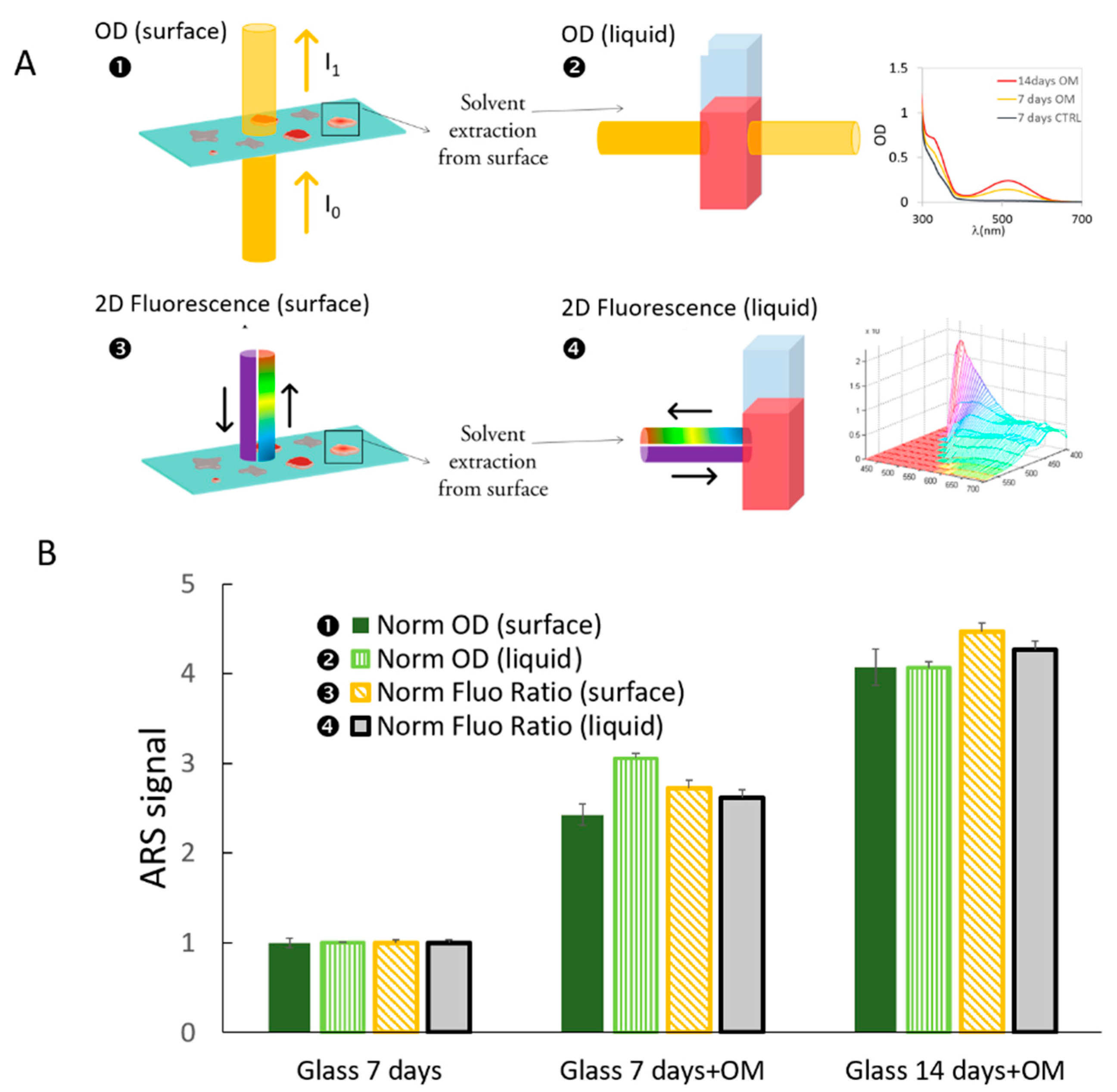
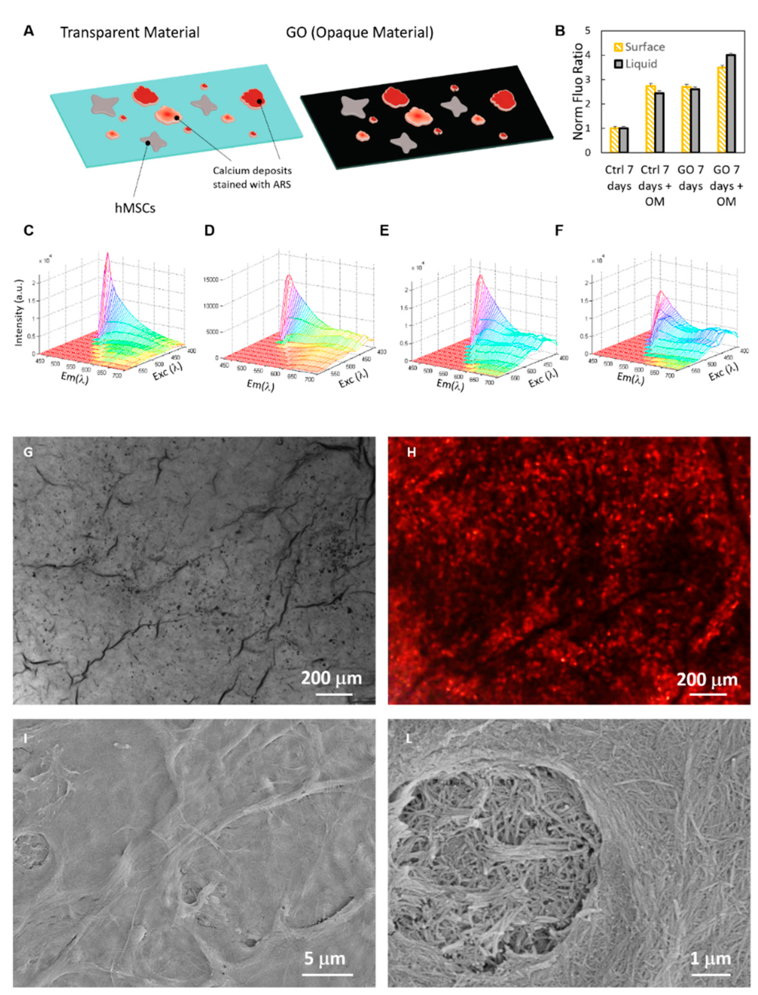
2. Results
3. Discussion
4. Materials and Methods
4.1. Cell Cultures
4.2. Spectroscopy and Microscopy Measurements
Author Contributions
Funding
Acknowledgments
Conflicts of Interest
Abbreviations
| ARS | Alizarin Red S |
| CMSC | Calvarial-derived mesenchimal stem cells |
| DMEM | Dulbecco’s modified Eagle medium |
| EXC | Excitation |
| GO | Graphene oxide |
| OD | Optical density |
| OM | Osteogenic medium |
| SEM | Scanning electron microscopy |
References
- Palmieri, V.; Barba, M.; Di Pietro, L.; Gentilini, S.; Braidotti, M.C.; Ciancico, C.; Bugli, F.; Ciasca, G.; Larciprete, R.; Lattanzi, W. Reduction and shaping of graphene-oxide by laser-printing for controlled bone tissue regeneration and bacterial killing. 2D Mater. 2017, 5, 015027. [Google Scholar] [CrossRef] [Green Version]
- Akhavan, O.; Ghaderi, E.; Shahsavar, M. Graphene nanogrids for selective and fast osteogenic differentiation of human mesenchymal stem cells. Carbon 2013, 59, 200–211. [Google Scholar] [CrossRef]
- Gregory, C.A.; Gunn, W.G.; Peister, A.; Prockop, D.J. An Alizarin red-based assay of mineralization by adherent cells in culture: Comparison with cetylpyridinium chloride extraction. Anal. Biochem. 2004, 329, 77–84. [Google Scholar] [CrossRef] [PubMed]
- Navarro, M.; Michiardi, A.; Castano, O.; Planell, J. Biomaterials in orthopaedics. J. R. Soc. Interface 2008, 5, 1137–1158. [Google Scholar] [CrossRef] [PubMed] [Green Version]
- Albrektsson, T. Hard tissue implant interface. Aust. Dent. J. 2008, 53, S34–S38. [Google Scholar] [CrossRef] [PubMed]
- Bruneel, B.; Mathae, M.; Paesen, R.; Ameloot, M.; Weninger, W.J.; Huysseune, A. Imaging the Zebrafish Dentition: From Traditional Approaches to Emerging Technologies. Zebrafish 2015, 12, 1–10. [Google Scholar] [CrossRef] [PubMed] [Green Version]
- Connolly, M.; Yelick, P. High-throughput methods for visualizing the teleost skeleton: Capturing autofluorescence of alizarin red. J. Appl. Ichthyol. 2010, 26, 274–277. [Google Scholar] [CrossRef]
- Asghari, F.; Salehi, R.; Agazadeh, M.; Alizadeh, E.; Adibkia, K.; Samiei, M.; Akbarzadeh, A.; Aval, N.A.; Davaran, S. The odontogenic differentiation of human dental pulp stem cells on hydroxyapatite-coated biodegradable nanofibrous scaffolds. Int. J. Polym. Mater. Polym. Biomater. 2016, 65, 720–728. [Google Scholar] [CrossRef]
- Palmieri, V.; Papi, M.; Conti, C.; Ciasca, G.; Maulucci, G.; De Spirito, M. The future development of bacteria fighting medical devices: The role of graphene oxide. Expert Rev. Med. Devices 2016, 13, 1013–1019. [Google Scholar] [CrossRef] [PubMed]
- Papi, M.; Palmieri, V.; Bugli, F.; De Spirito, M.; Sanguinetti, M.; Ciancico, C.; Braidotti, M.C.; Gentilini, S.; Angelani, L.; Conti, C. Biomimetic antimicrobial cloak by graphene-oxide agar hydrogel. Sci. Rep. 2016, 6. [Google Scholar] [CrossRef] [PubMed] [Green Version]
- Palmieri, V.; Bugli, F.; Lauriola, M.C.; Cacaci, M.; Torelli, R.; Ciasca, G.; Conti, C.; Sanguinetti, M.; Papi, M.; De Spirito, M. Bacteria meet graphene: Modulation of graphene oxide nanosheet interaction with human pathogens for effective antimicrobial therapy. ACS Biomater. Sci. Eng. 2017, 3, 619–627. [Google Scholar] [CrossRef]
- Palmieri, V.; Lauriola, M.C.; Ciasca, G.; Conti, C.; De Spirito, M.; Papi, M. The graphene oxide contradictory effects against human pathogens. Nanotechnology 2017, 28, 152001. [Google Scholar] [CrossRef] [PubMed]
- Papi, M.; Lauriola, M.; Palmieri, V.; Ciasca, G.; Maulucci, G.; De Spirito, M. Plasma protein corona reduces the haemolytic activity of graphene oxide nano and micro flakes. RSC Adv. 2015, 5, 81638–81641. [Google Scholar] [CrossRef]
- Zancanela, D.C.; Simão, A.M.S.; Francisco, C.G.; de Faria, A.N.; Ramos, A.P.; Gonçalves, R.R.; Matsubara, E.Y.; Rosolen, J.M.; Ciancaglini, P. Graphene oxide and titanium: Synergistic effects on the biomineralization ability of osteoblast cultures. J. Mater. Sci. Mater. Med. 2016, 27, 1–9. [Google Scholar] [CrossRef] [PubMed]
- Nayak, T.R.; Andersen, H.; Makam, V.S.; Khaw, C.; Bae, S.; Xu, X.; Ee, P.-L.R.; Ahn, J.-H.; Hong, B.H.; Pastorin, G. Graphene for controlled and accelerated osteogenic differentiation of human mesenchymal stem cells. ACS Nano 2011, 5, 4670–4678. [Google Scholar] [CrossRef] [PubMed]
- Kalbacova, M.; Broz, A.; Kong, J.; Kalbac, M. Graphene substrates promote adherence of human osteoblasts and mesenchymal stromal cells. Carbon 2010, 48, 4323–4329. [Google Scholar] [CrossRef]
- Holt, B.D.; Wright, Z.M.; Arnold, A.M.; Sydlik, S.A. Graphene oxide as a scaffold for bone regeneration. Wiley Interdiscip. Rev. Nanomed. Nanobiotechnol. 2017, 9, e1437. [Google Scholar] [CrossRef] [PubMed]
- Lee, W.C.; Lim, C.H.Y.; Shi, H.; Tang, L.A.; Wang, Y.; Lim, C.T.; Loh, K.P. Origin of enhanced stem cell growth and differentiation on graphene and graphene oxide. ACS Nano 2011, 5, 7334–7341. [Google Scholar] [CrossRef] [PubMed]
- Muto, A.; Kawakami, K. Imaging functional neural circuits in zebrafish with a new GCaMP and the Gal4FF-UAS system. Commun. Integr. Biol. 2011, 4, 566–568. [Google Scholar] [CrossRef] [PubMed]
- Muto, A.; Ohkura, M.; Kotani, T.; Higashijima, S.-I.; Nakai, J.; Kawakami, K. Genetic visualization with an improved GCaMP calcium indicator reveals spatiotemporal activation of the spinal motor neurons in zebrafish. Proc. Natl. Acad. Sci. USA 2011, 108, 5425–5430. [Google Scholar] [CrossRef] [PubMed] [Green Version]
- Lee, D.J.; Tseng, H.C.; Wong, S.W.; Wang, Z.; Deng, M.; Ko, C.-C. Dopaminergic effects on in vitro osteogenesis. Bone Res. 2015, 3, 15020. [Google Scholar] [CrossRef] [PubMed] [Green Version]
- Tancred, D.; McCormack, B.; Carr, A. A synthetic bone implant macroscopically identical to cancellous bone. Biomaterials 1998, 19, 2303–2311. [Google Scholar] [CrossRef]
- Raghavan, S.; Nelson, C.M.; Baranski, J.D.; Lim, E.; Chen, C.S. Geometrically controlled endothelial tubulogenesis in micropatterned gels. Tissue Eng. Part A 2010, 16, 2255–2263. [Google Scholar] [CrossRef] [PubMed]
- Bensimon-Brito, A.; Cardeira, J.; Dionísio, G.; Huysseune, A.; Cancela, M.; Witten, P. Revisiting in vivo staining with alizarin red S-a valuable approach to analyse zebrafish skeletal mineralization during development and regeneration. BMC Dev. Biol. 2016, 16, 2. [Google Scholar] [CrossRef] [PubMed] [Green Version]
- Lattanzi, W.; Barba, M.; Novegno, F.; Massimi, L.; Tesori, V.; Tamburrini, G.; Galgano, S.; Bernardini, C.; Caldarelli, M.; Michetti, F. Lim mineralization protein is involved in the premature calvarial ossification in sporadic craniosynostoses. Bone 2013, 52, 474–484. [Google Scholar] [CrossRef] [PubMed]
- Barba, M.; Pirozzi, F.; Saulnier, N.; Vitali, T.; Natale, M.T.; Logroscino, G.; Robbins, P.D.; Gambotto, A.; Neri, G.; Michetti, F. Lim mineralization protein 3 induces the osteogenic differentiation of human amniotic fluid stromal cells through Kruppel-like factor-4 downregulation and further bone-specific gene expression. BioMed Res. Int. 2012, 2012, 813894. [Google Scholar] [CrossRef] [PubMed]
- Bernardini, C.; Saulnier, N.; Parrilla, C.; Pola, E.; Gambotto, A.; Michetti, F.; Robbins, P.D.; Lattanzi, W. Early transcriptional events during osteogenic differentiation of human bone marrow stromal cells induced by Lim mineralization protein 3. Gene Expr. 2010, 15, 27–42. [Google Scholar] [CrossRef] [PubMed]
- Parrilla, C.; Lattanzi, W.; Rita Fetoni, A.; Bussu, F.; Pola, E.; Paludetti, G. Ex vivo gene therapy using autologous dermal fibroblasts expressing hLMP3 for rat mandibular bone regeneration. Head Neck 2010, 32, 310–318. [Google Scholar] [CrossRef] [PubMed]
- Schindelin, J.; Arganda-Carreras, I.; Frise, E.; Kaynig, V.; Longair, M.; Pietzsch, T.; Preibisch, S.; Rueden, C.; Saalfeld, S.; Schmid, B. Fiji: An open-source platform for biological-image analysis. Nat. Methods 2012, 9, 676–682. [Google Scholar] [CrossRef] [PubMed]
- Garg, S.; Valente, E.; Greco, E.; Santucci, M.; De Spirito, M.; Papi, M.; Bocchino, M.; Saltini, C.; Fraziano, M. Lysophosphatidic acid enhances antimycobacterial activity both in vitro and ex vivo. Clin. Immunol. 2006, 121, 23–28. [Google Scholar] [CrossRef] [PubMed]
- Palmieri, V.; Lucchetti, D.; Maiorana, A.; Papi, M.; Maulucci, G.; Ciasca, G.; Svelto, M.; De Spirito, M.; Sgambato, A. Biomechanical investigation of colorectal cancer cells. Appl. Phys. Lett. 2014, 105, 123701. [Google Scholar] [CrossRef]


© 2018 by the authors. Licensee MDPI, Basel, Switzerland. This article is an open access article distributed under the terms and conditions of the Creative Commons Attribution (CC BY) license (http://creativecommons.org/licenses/by/4.0/).
Share and Cite
Palmieri, V.; Barba, M.; Di Pietro, L.; Conti, C.; De Spirito, M.; Lattanzi, W.; Papi, M. Graphene Oxide Induced Osteogenesis Quantification by In-Situ 2D-Fluorescence Spectroscopy. Int. J. Mol. Sci. 2018, 19, 3336. https://doi.org/10.3390/ijms19113336
Palmieri V, Barba M, Di Pietro L, Conti C, De Spirito M, Lattanzi W, Papi M. Graphene Oxide Induced Osteogenesis Quantification by In-Situ 2D-Fluorescence Spectroscopy. International Journal of Molecular Sciences. 2018; 19(11):3336. https://doi.org/10.3390/ijms19113336
Chicago/Turabian StylePalmieri, Valentina, Marta Barba, Lorena Di Pietro, Claudio Conti, Marco De Spirito, Wanda Lattanzi, and Massimiliano Papi. 2018. "Graphene Oxide Induced Osteogenesis Quantification by In-Situ 2D-Fluorescence Spectroscopy" International Journal of Molecular Sciences 19, no. 11: 3336. https://doi.org/10.3390/ijms19113336