Article

A Carbon Nanotube-based Sensor for CO2 Monitoring

Department of Electrical Engineering & Materials Research Institute, 208 Materials Research Laboratory, The Pennsylvania State University, University Park, PA 16802, USA
*
Author to whom correspondence should be addressed.
Sensors 2001, 1(6), 193-205; https://doi.org/10.3390/s10600193
Submission received: 8 October 2001 / Accepted: 17 October 2001 / Published: 2 November 2001

Abstract

:
A carbon dioxide (CO2) sensor is fabricated by depositing a thin layer of a multi- wall carbon nanotube (MWNT) – silicon dioxide (SiO2) composite upon a planar inductor- capacitor resonant circuit. By tracking the resonant frequency of the sensor the complex permittivity of the coating material can be determined. It is shown that the permittivity of MWNTs changes linearly in response to CO2 concentration, enabling monitoring of ambient CO2 levels. The passive sensor is remotely monitored with a loop antenna, enabling measurements from within opaque, sealed containers. Experimental results show the response of the sensor is linear, reversible with no hysteresis between increasing and decreasing CO2 concentrations, and with a response time of approximately 45 s. An array of three such sensors, comprised of an uncoated, SiO2 coated, and a MWNT-SiO2 coated sensors is used to self-calibrate the measurement for operation in a variable humidity and temperature environment. Using the sensor array CO2 levels can be measured in a variable humidity and temperature environment to a ± 3% accuracy.

Introduction

Carbon nanotubes, molecular-scale tubes of carbon with high mechanical strength and unique electrical properties, have seen considerable interest in recent years for applications including, to name a few, field emission devices [1], nano-electronic devices [2,3,4,5], actuators [6], and random access memory [7]. Carbon nanotubes have successfully been used as oxygen [8] and methane [9] gas sensors.
In this paper we report, apparently for the first time, application of multi-wall carbon nanotubes (MWNTs) to carbon dioxide sensing, based upon the measured changes in MWNT permittivity with CO2 exposure. The transduction platform used in this work is a planar, inductor-capacitor resonant- circuit (LC) sensor [10,11]. A thin layer of a MWNT-SiO2 composite is placed upon the inter-digital capacitor of the LC sensor; as the permittivity of the adjacent layer changes so does the sensor resonant frequency which is remotely monitored using a loop antenna [10]. The passive nature of the LC sensor enables long term monitoring without battery life-time issues, and the wireless nature of the platform enables monitoring of CO2 from within sealed, opaque containers such as food or medicine packages. High levels of CO2 within such containers are widely used as a determinant for contamination [12,13]. In addition to food quality monitoring CO2 sensors are important for industrial process control [14], monitoring air quality [15], etc.
Most CO2 sensors available on the market today operate by measuring the impedance of a capacitor coated with a CO2-responsive material such as heteropolysiloxane [16], BaTiO3 [17], CeO/BaCO3/CuO [18], Ag2SO4 [19], and Na2CO3 [19]. These CO2 sensors offer a high degree of accuracy and reliable performance, but require hard-wire connections between the sensor head, power supply, and data processing electronics which precludes many monitoring applications.
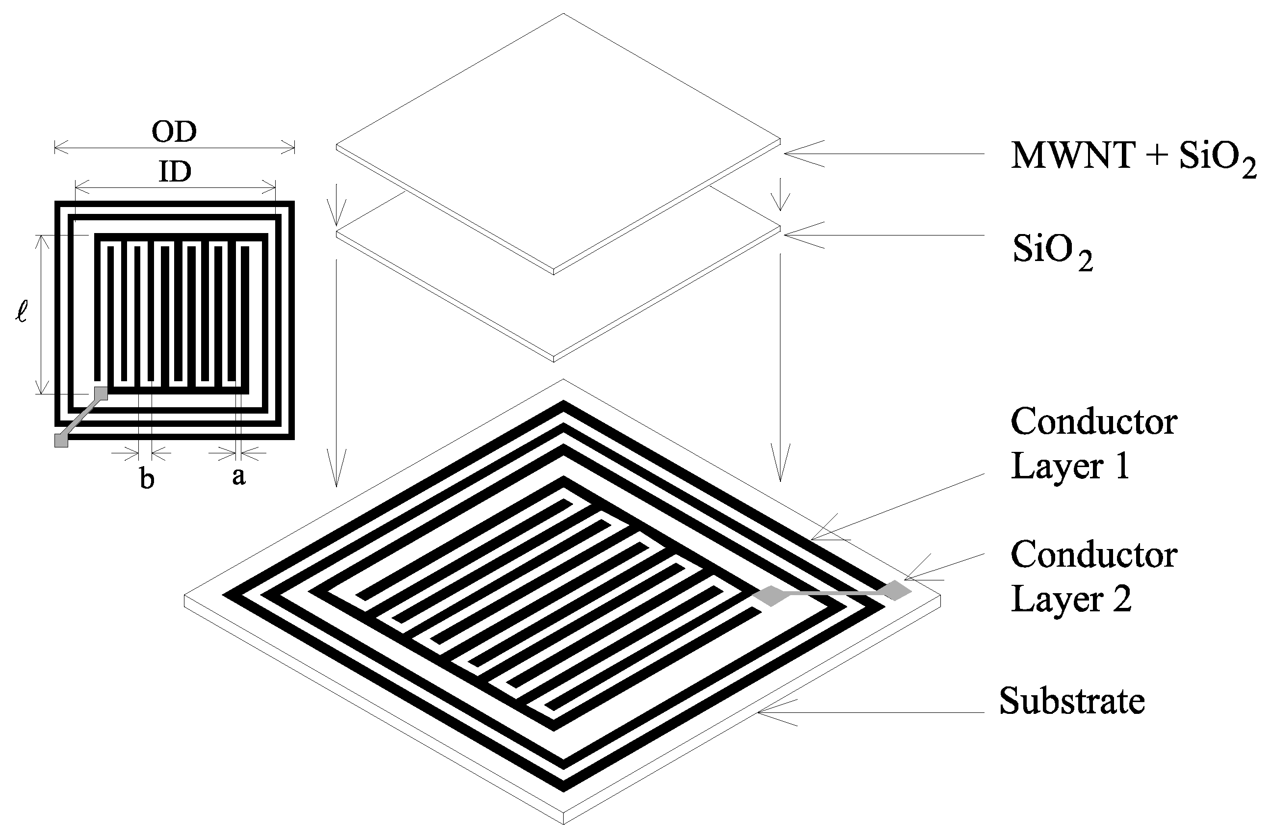
Figure 1. The schematic drawing of the CO2 sensor. A planar inductor-interdigital capacitor pair is photolithographically defined upon a copper clad printed circuit board. The capacitor is first coated with a protective electrically insulating SiO2 layer followed by a layer of CO2 responsive MWNT-SiO2 composite.
Sensors 01 00193 g001
The general sensor structure is shown in Figure 1, and consists of a printed inductor-capacitor resonant circuit that is first coated with a protective, electrically insulating SiO2 layer [20], followed by a second layer consisting of the CO2 responsive MWNT-SiO2 mixture with the SiO2 matrix acting to physically bind the MWNTs to the sensor. As the sensor is exposed to CO2 the relative permittivity εr and the conductivity (proportional to εr [21]) of the MWNTs vary, changing the effective complex permittivity of the coating and hence the resonant frequency of the sensor. The relationship between the CO2 adsorption and the complex permittivity is discussed within the Results & Discussion.
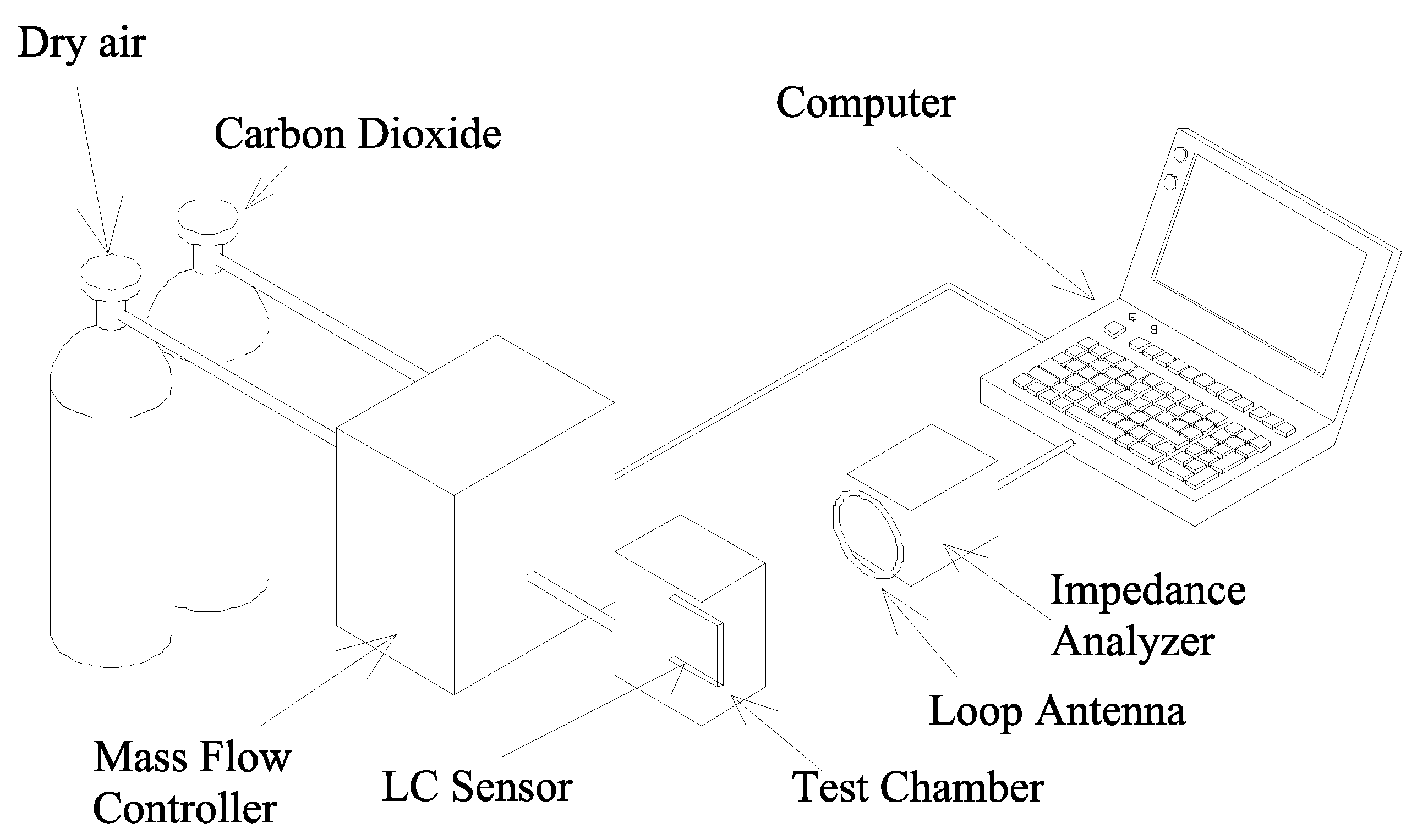
Figure 2. Experimental setup for testing the CO2 sensor. The sensor is placed inside a sealed Plexiglas chamber, and monitored via a loop antenna. An impedance analyzer is used to measure the impedance spectrum across the terminals of the antenna, and a mass-flow controller is used to control the flow rates of different gasses. A computer controls the devices via the GPIB interface.
Sensors 01 00193 g002
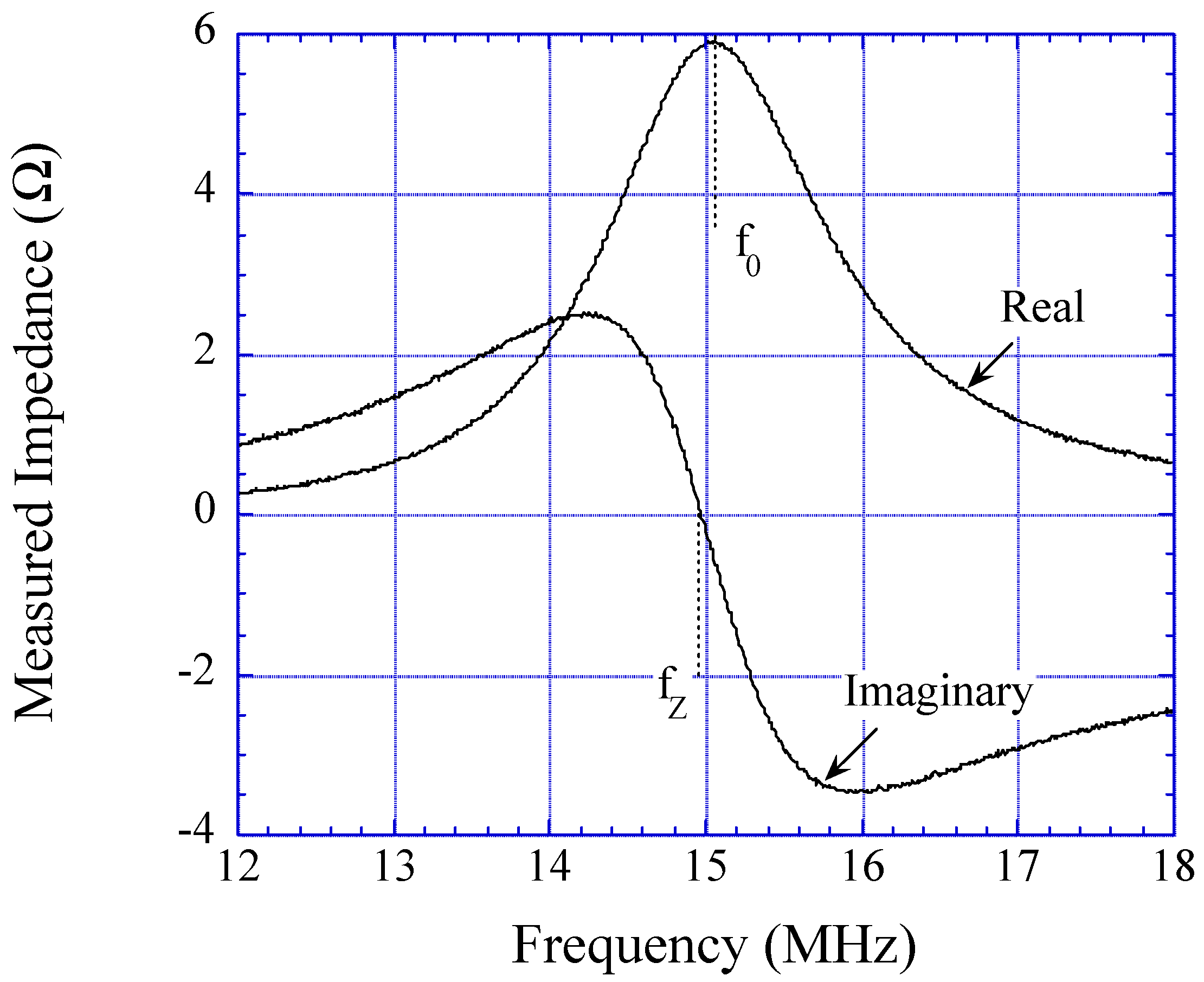
As shown in Figure 2, the response of the CO2 sensor is obtained by directly measuring the impedance spectrum of a sensor-monitoring loop antenna. The impedance of the loop antenna is removed from the measurement using a background subtraction, obtained by measuring the antenna impedance without the sensor present. A typical background-subtracted impedance spectrum is shown in Figure 3, where the resonant frequency f0 is defined as the frequency at the real impedance (resistance) maximum, and the zero-reactance frequency fZ is the frequency where the imaginary impedance (reactance) goes to zero. By modeling the sensor with an RLC circuit and performing standard circuit analysis, the complex permittivity, εrr, of the coating material (both the MWNT- SiO2 and SiO2 layers) are calculated from the measured f0 and fZ as [10,11]:
Sensors 01 00193 i001
ε0 is the free space permittivity (ε0 = 8.854 × 10⁻¹² Farads / meter ), εs is the relative permittivity of the electrically lossless substrate (that is εs = εs), κ is the cell constant of the interdigital capacitor, and L is the inductance of the spiral inductor in Henry’s. The cell constant κ and inductance L can be calculated from the sensor geometry using [22,23,24]:
Sensors 01 00193 i002
Sensors 01 00193 i003
where a, b, , OD, and ID are the dimensions of the sensor defined in Figure 1, NC is the number of fingers in each capacitor’s electrode, NL is the number of the inductor turns, and K is the elliptic integral of the first kind.
Figure 3. An illustrative measured impedance spectrum of the sensor-perturbed antenna, after subtracting the background antenna impedance. The resonant frequency f0 is defined as the maximal of the real portion of the impedance, and the zero-reactance frequency fZ is the zero crossing of the imaginary portion of the impedance spectrum.
Sensors 01 00193 g003

Experimental

Preparation of nanotubes
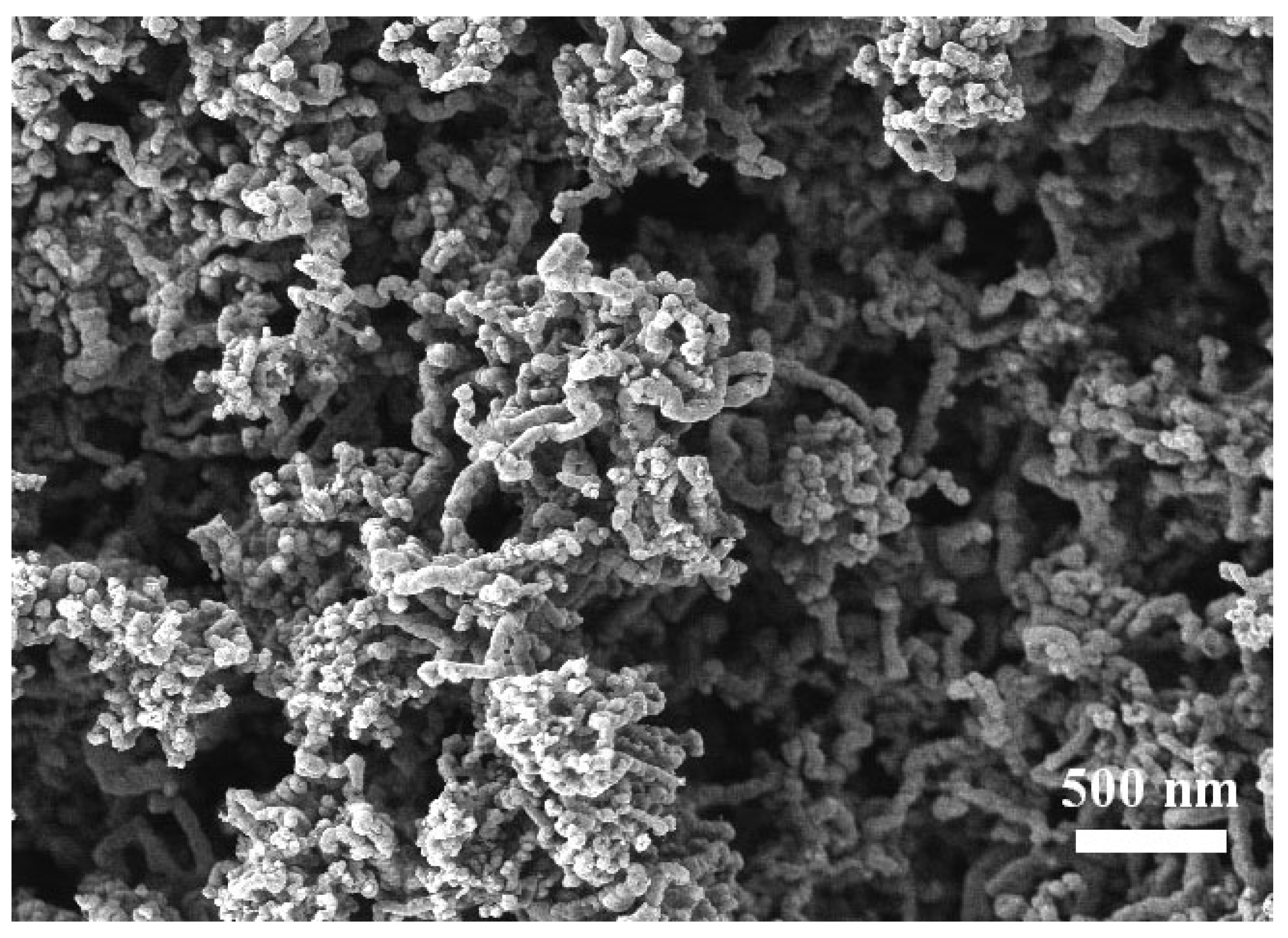
The MWNTs used in this work were prepared by pyrolysis of ferrocene and xylene under Ar/H2 atmosphere over quartz substrates in a two-stage reactor [25]. Approximately 6.5 mol% of ferrocene was dissolved in xylene and continuously fed into a tubular quartz reactor. Ferrocene has been shown to be an excellent precursor for producing Fe catalyst particles, and xylene was selected as the hydrocarbon source. The liquid feed was passed through a capillary tube and preheated to ~175°C prior to its entry into the furnace. At this temperature, the liquid exiting the capillary was immediately volatilized and swept into the reaction zone of the furnace by a flow of argon with 10% hydrogen. The MWNTs grow perpendicularly from the surface of the quartz reactor tube. After the reaction, the pre- heater and the furnace were allowed to cool to room temperature in flowing argon, and the MWNT sheets collected. Precise details of the fabrication process are described in [25].
The resulting MWNTs were characterized by field-emission scanning electron microscopy, and shown in Figure 4. These studies confirm the collected material consists of highly aligned MWNTs with the dominant tube diameter in the range 20-25 nm with length 50 µm. The MWNT clumps were placed in toluene and then sonicated for 30 minutes to disperse the individual nanotubes, rinsed with isopropanol, and then allowed to dry. The nanotubes were then dispersed in a liquid SiO2 solution (20 wt% SiO2 nanoparticles dispersed in water, from [20]) such that a nanotube to SiO2 dry-weight balance of 2:3 was obtained. The resulting solution was pipetted onto the inter-digital capacitor of the sensor.
Figure 4. The SEM image of the as-fabricated carbon nanotubes. The carbon nanotubes are about 25-50 nm in diameter, and 50 µm in length.
Sensors 01 00193 g004

Sensor Fabrication

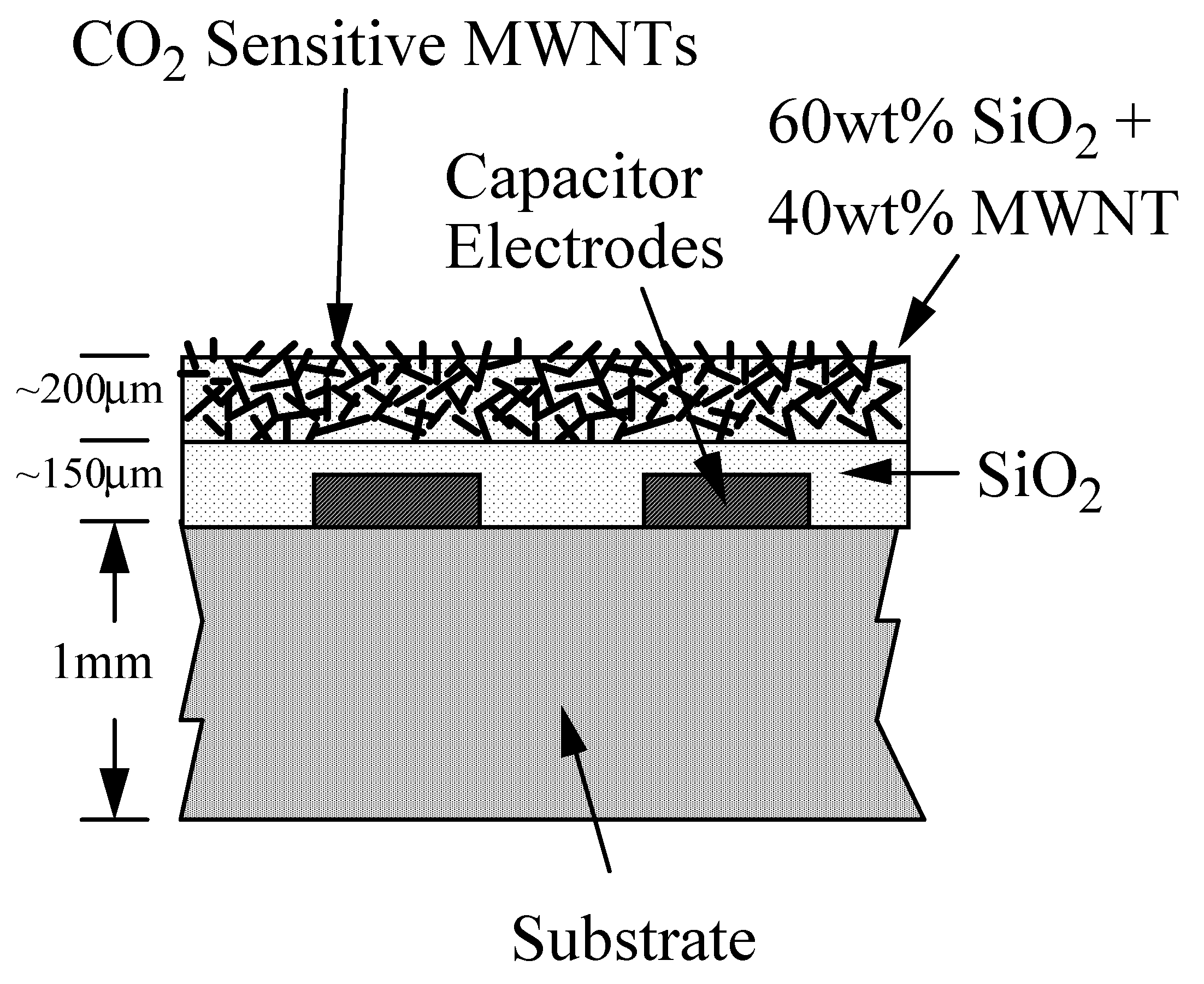
A 2-cm square sensor was fabricated by photolithographically patterning a square spiral inductor and an interdigital capacitor on a Printed Circuit Board (PCB), see Figure 1. An ≈ 150 µm thick layer of SiO2 (confirmed by SEM imaging) followed by an ≈200 µm thick layer the MWNT-SiO2 mixture were then coated onto the capacitor of the sensor, with a resulting sensor cross section as shown schematically in Figure 5.
Figure 5. Cross sectional view of the interdigital capacitor. An electrically insulating 150 μm- thick SiO2 layer is first applied to protect the sensor, followed by a 200 µm MWNT-SiO2 gas- sensing layer.
Sensors 01 00193 g005

Experimental Setup for Sensing CO2

The testing facility is schematically depicted in Figure 2. The sensor was placed inside a sealed Plexiglas test chamber, and monitored with a single-turn 16 cm diameter loop-antenna located approximately 15 cm from the sensor. Test gas concentration was controlled with a mass flow controller (MKS Instruments Multi Gas Controller 647B). The antenna impedance was measured with an impedance analyzer (Hewlett Packard 4396B), with the cable length removed from the measurement using an HP85033D calibration kit. A computer was used to control the mass flow controller and the impedance analyzer via a GPIB interface, as well as analyzing and processing the measurements.

Results and Discussion

CO2 Detection
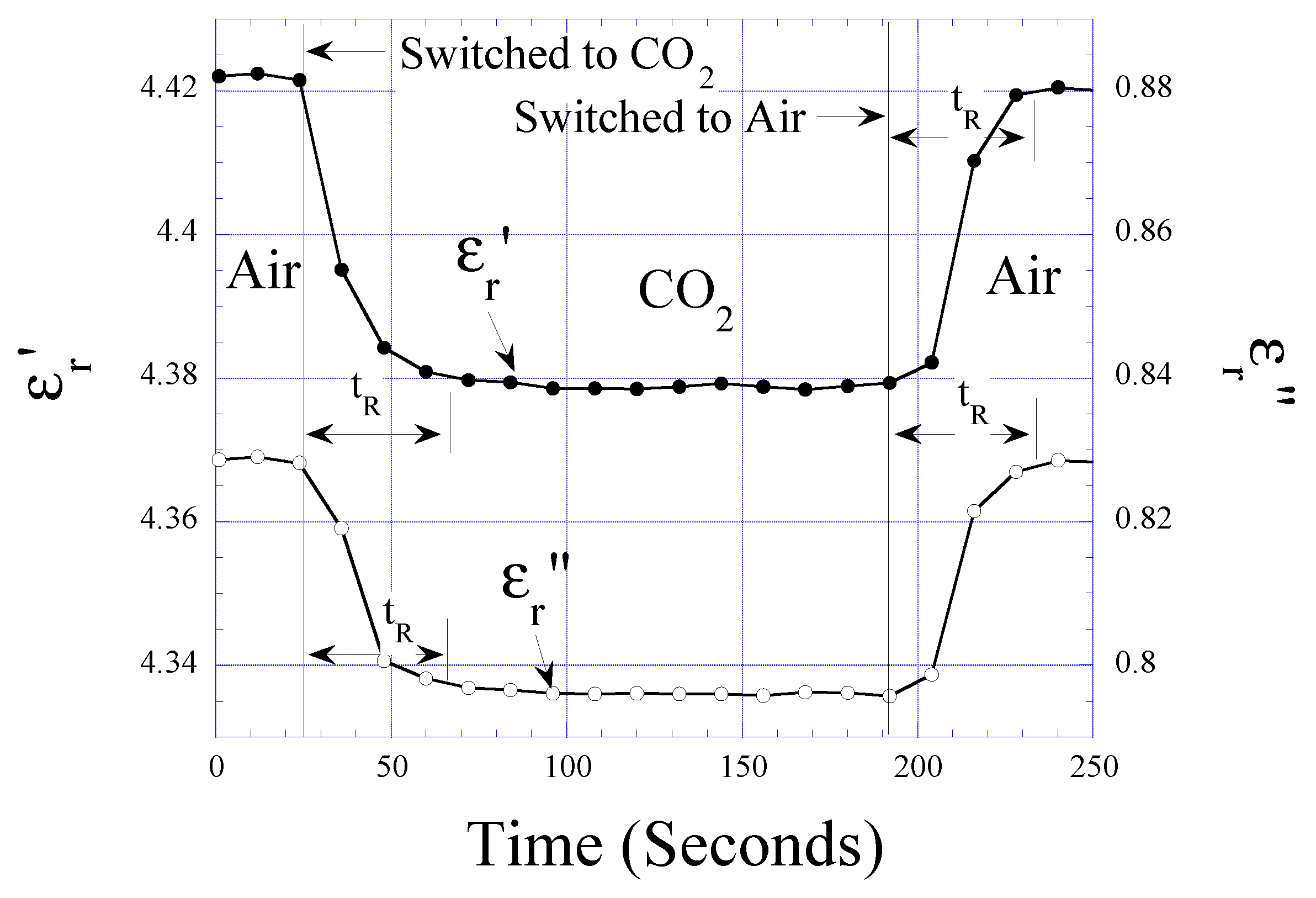
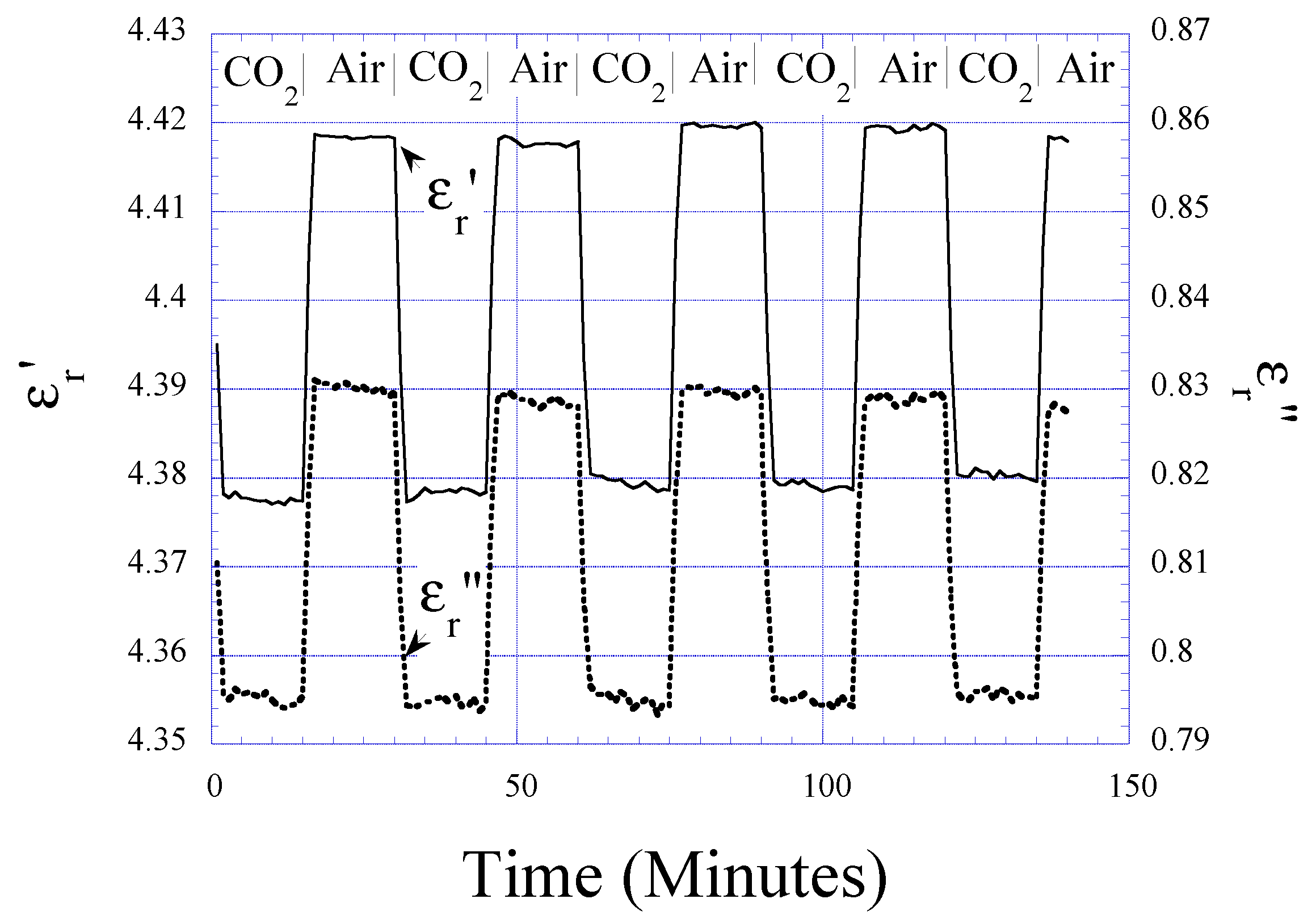
Figure 6 shows the response of the CO2 sensor as it is alternately cycled between dry air (~80% N2 and 20% O2) and pure CO2; the humidity level in the chamber was 0% RH, and the temperature was 23°C. There is an increase in values of εr and εr, 0.040 (0.91%) and 0.035 (4.40%), respectively, as the gas is switched from CO2 to dry air. The change in the complex permittivity magnitude |εr| is 1.02%. The change in the complex permittivity is reversible, with no hysteresis observed.
Figure 6. Measured εr and εr values when the sensor is cycled between pure CO2 and dry air. The changes are reversible, without hysteresis between increasing and decreasing CO2 concentrations.
Sensors 01 00193 g006
As seen in Figure 6 both εr and εr of the MWNTs are lower when the sensor is exposed to CO2 and higher when the sensor is exposed to dry air containing ~80 %N2 and 20 % O2. We believe that the change in εr, which is directly proportional to the conductivity σ = 2πf ε0εr, is due to the adsorption and/or the insertion of gas molecules into either the core or surface of the MWNT that introduces defects and lowers the electrical conductivity [26]. As CO2, N2, and O2 have a relative low εr value (~1) compared to the MWNT graphene layer (εr~15), the effective εr of the exposed MWNT layer decreases as more gas molecules are adsorbed. Since CO2 has two lone pair of electrons with Π-type C=O bindings [27] and N2 is an inert diatomic molecule that only reacts to graphene at high temperature [28], the adsorption capacity of CO2 is much higher than N2 at room temperature. Hence, there is a decrease in εr and εr when the sensor is exposed to CO2. While O2, which has two lone-pair of electrons in the anti-bonding Π orbital [29], has similar adsorption behavior as CO2 it is not present in sufficient quantity to completely counter the N2 effect. Our observations on εr (conductivity) decreasing with gas adsorption are consistent with those reported elsewhere [26,28,30,31].
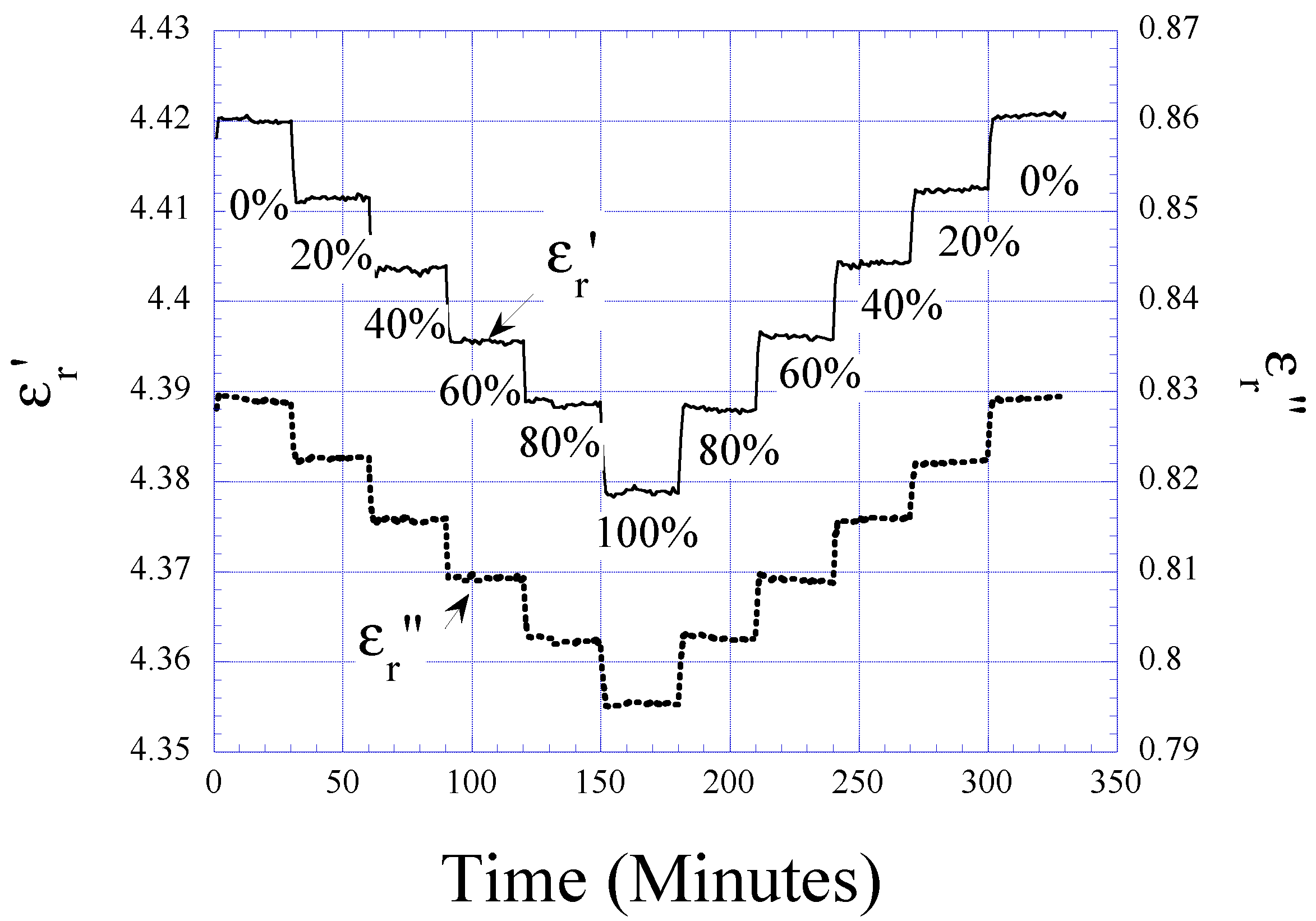
Figure 7. Measured εr and εr values when the sensor is exposed to CO2 concentrations varying from 0% (volume) to 100% and then back to 0%. The shifts are linear, with Δεr = - 0.0004043/%CO2 and Δεr = -0.0003476/%CO2.
Sensors 01 00193 g007
Figure 8. Change in εr and εr when the gas is switched from air to CO2, and then back to air. The response time tR, can be determined from the figure as less than 45 seconds.
Sensors 01 00193 g008
Figure 7 presents the shifts of εr and εr as a function of the CO2 to dry air volume ratio. The symmetry of the steps indicates the absence of hysteresis with increasing or decreasing CO2 concentrations. The absolute change in the complex permittivity with CO2 concentration is linear at Δεr = -0.0004043/%CO2 and Δεr = -0.0003476/%CO2. The response time of the sensor tR, determined as the time to achieve steady state response after switching gas concentrations, is determined from Figure 8 as approximately 45 s, and was found to be constant with temperature to 43°C, the upper limit tested.

Humidity and Temperature Dependencies

Figure 9a displays the effect of changing humidity, temperature, and CO2 concentration on the complex permittivity magnitude of the MWNT- SiO2 sensor coating. Figure 9b is an illustrative real- time measurement showing how the permittivity magnitude of the MWNT CO2 sensor changes, at CO2 concentration = 0% and 25%, in response to various humidity and temperature conditions. Due to the strong attraction of the MWNTs for water moisture the response time of the CO2 sensor suffers a dramatic increase in high humidity environments. Operation at elevated temperatures improves the response time of the sensor as it is cycled between dry and humid environments. Switching from 0% to 100% humidity levels at 23°C, 31°C, and 42°C the response times are, respectively, 22, 16 and 14 minutes. Switching from 100% to 0% humidity levels at 23°C, 31°C, and 42°C the response times are, respectively, 58, 36 and 34 minutes.
Figure 9. (a) The permittivity magnitude of the MWNT-based CO2 sensor shifts linearly with CO2, humidity, and temperature. (b) The permittivity magnitude of the MWNT-based CO2 sensor, at zero and 25% CO2 concentration, as it is exposed to different humidity and temperature conditions.
Sensors 01 00193 g009
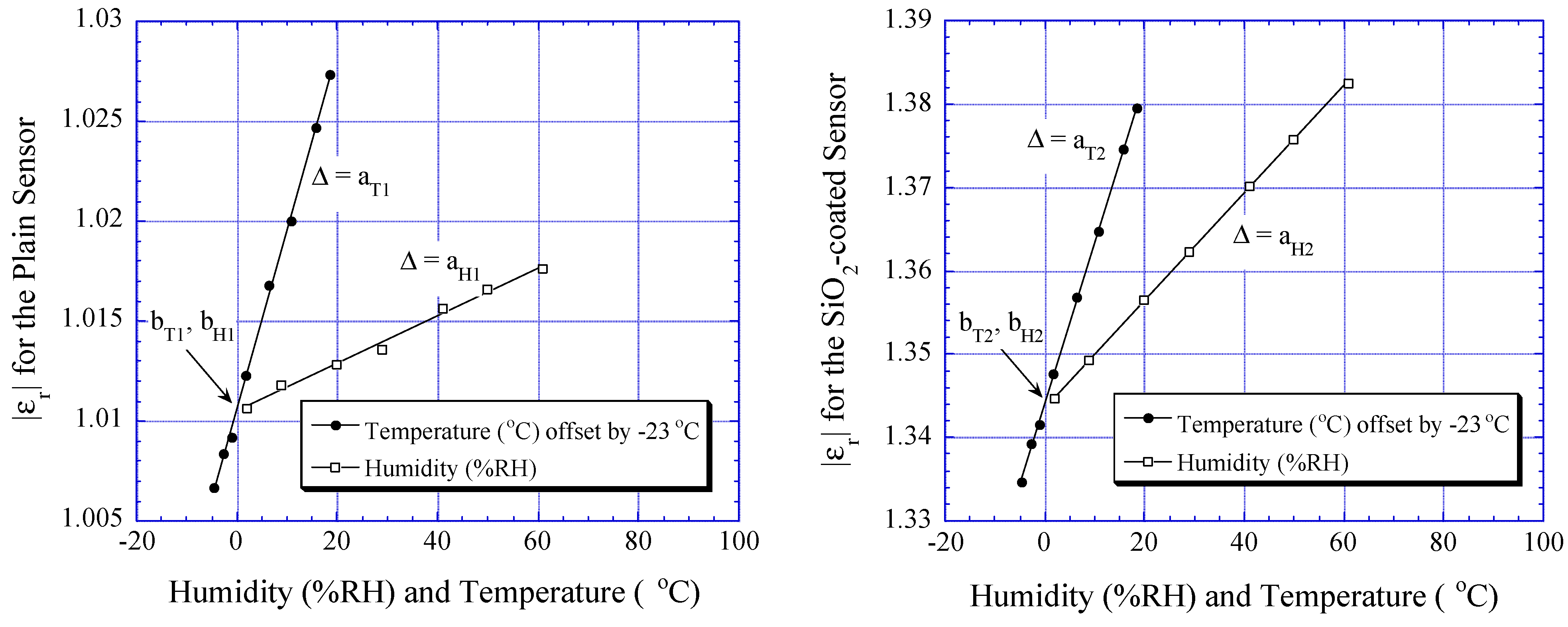
To eliminate the effects of humidity and temperature, a SiO2-coated sensor and an uncoated sensor are used in addition to the CO2 sensor, forming a sensor array. The SiO2-coated and the plain sensors do not respond to CO2, but both linearly respond in separable ways to humidity and temperature, over the range investigated 0 - 60% RH and 18°C - 43°C, as shown in Fig. 9a and Fig. 9b. Since their responses to both humidity and temperature are linear, the complex permittivity magnitude of the plain sensor εr1, and the SiO2-coated sensor εr2, can be related to humidity and temperature as:
Sensors 01 00193 i004
Sensors 01 00193 i005
H is humidity in %RH, T is temperature in °C, while a and b are coefficients experimentally determined by curve-fitting the data in Figure 10a and Figure 10b and listed in Table 1. In our experiment, T was offset by -23°C (i.e. T = 0 means T = 23°C in the real world); the offset is required since the sensor is initially calibrated at room temperature (23°C).
Table 1. Regression coefficients of plain, SiO2 coated, and MWNT-SiO2 coated sensors.
CoefficientsPlain SensorSiO2-coated SensorMWNT-coated Sensor
aTaT1 = 0.00089523aT2 = 0.00193071aT3 = 0.024175
bTbT1 = 1.01062bT2 = 1.34392bT3 = 4.49524
aHaH1 = 0.00011883aH2 = 0.00064168aH3 = 0.0052665
bHbH1 = 1.01051bH2 = 1.34359bH3 = 4.49472
aX00aX3 = -0.00045769
bX00bX3 = 4.49562
Figure 10. (a) The permittivity magnitude of the plain (uncoated) sensor shifts linearly with humidity or temperature. (b) The permittivity magnitude of the SiO2-coated sensor shifts linearly with humidity or temperature; note response slopes of Figure 9a, Figure 10a and Figure 10b are uniquely different.
Sensors 01 00193 g010
The humidity and temperature can then be determined by simultaneously solving Eqs. (4) and (5):
Sensors 01 00193 i006
For the MWNT-SiO2 coated sensor the magnitude of the complex permittivity εr3can be related to humidity, temperature, and CO2 with the equation:
Sensors 01 00193 i007
X is the percent volume of CO2 present, and aT3, aH3, aX3, bT3, bH3, and bX3 are coefficients determined from Figure 9a listed in Table 1. Rearranging Eq. (7), the CO2 concentration can be found as:
Sensors 01 00193 i008
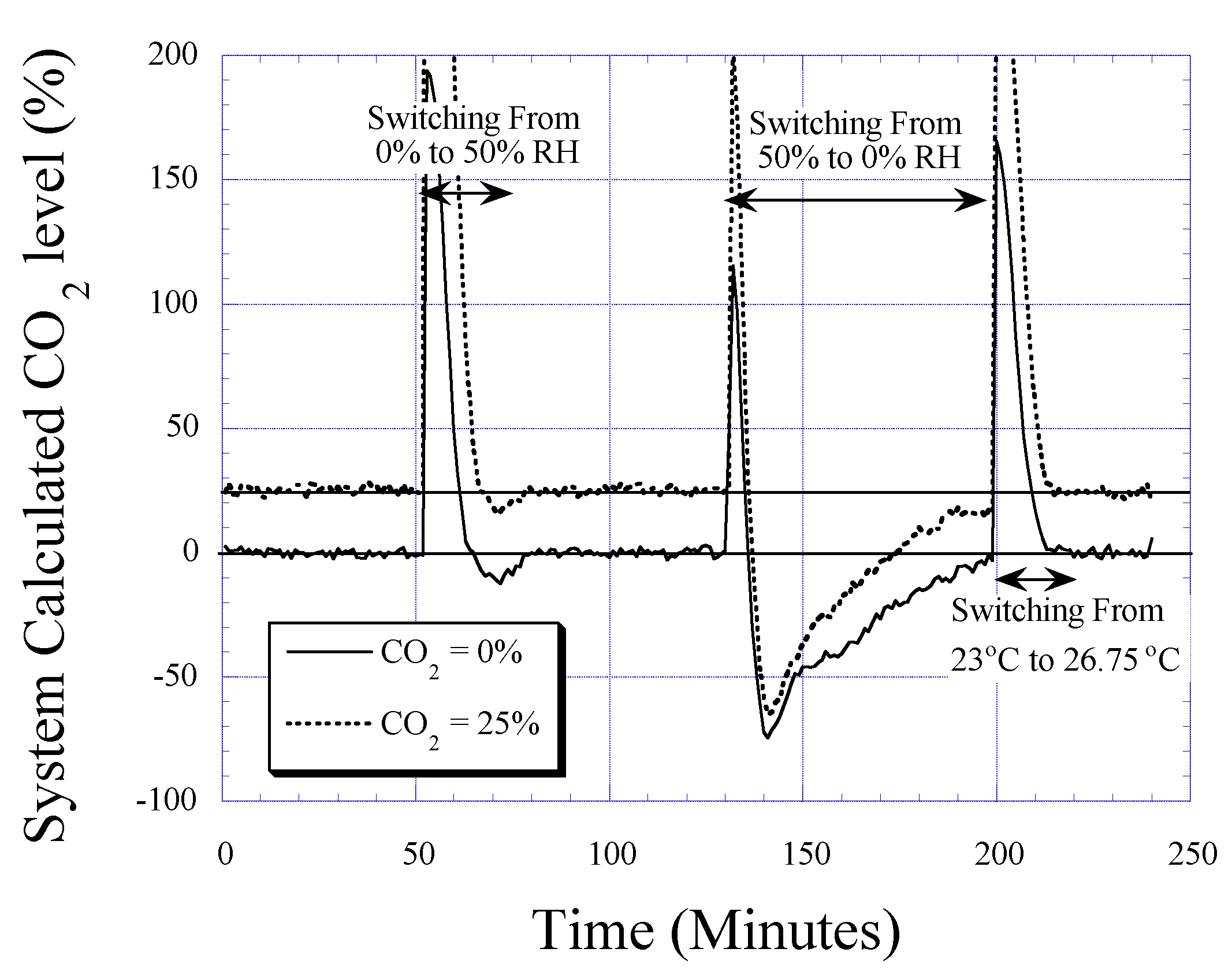
Figure 11 shows application of the sensor array to measurement of 0% and 25% CO2 atmospheres in a variable temperature and humidity environment; the CO2 percentage is calculated using Eq. (8) with data from Figure 9b. After a calibration transient due to the different response times of the sensors to changing temperature and humidity levels (primarily dictated by the strong attraction of MWNTs to water vapor), the calculated CO2 levels in a given humidity and temperature environment are within an error margin of ± 3 CO2%. However since the periods over which the sensor reports spurious measurement values are clearly discernable, both due to the rapid rate of change and clearly incorrect values (e.g. 120% CO2), software routines could be readily implemented to keep the sensor tracking nominal steady-state values.
Figure 11. CO2 concentration determined using measured data as corrected by Eq. 8 with calibration parameters of Table 1; measurements are taken with CO2 concentration kept at 0% and 25%. Outside of the transient region, upon reaching steady state measured results are within ± 3%. Since the different sensors have different response rates large errors occur when humidity and temperature change, an effect dominated by the slow desorption of moisture from the MWNTs.
Sensors 01 00193 g011

Conclusions

Application of multi-wall carbon nanotubes (MWNTs) to CO2 sensing has been demonstrated. The sensor is reversible, with no hysteresis observed between the cycles of CO2 and dry air (~20% O2 + 80% N2), with a response time of approximately 45 seconds. The MWNTs are used in combination with a passive, remote query sensor platform, therefore no direct wire connections to the sensor are needed for operation, nor is a battery needed to power the sensor. These operational characteristics make the CO2 sensor attractive for long-term wireless monitoring applications, such as monitoring CO2 levels in food or medicine packages to check for product spoilage [12,13].
It is found that the complex permittivity of the MWNTs is lower when the sensor is exposed to CO2 than in dry air. This is due to the relatively higher adsorption capacity of the MWNT for CO2 in comparison to N2, which increases the surface defects [26] and lowers the MWNT conductivity. Our observations on εr (conductivity) decreasing with gas adsorption are consistent with those reported elsewhere [26,28,30,31]. Absorption of CO2 also lowers εr of the MWNT, as εr of CO2 is much smaller than that of the electrically conductive MWNT. While O2, which has two lone-pair of electrons in the anti-bonding Π orbital [29], has similar adsorption behavior as CO2 it is not present in sufficient quantity to completely counter the N2 effect.
To eliminate the deleterious effects of humidity and temperature on the MWNT CO2 sensor, measured values are calibrated against the response of both a SiO2-coated sensor, and a plain (uncoated) sensor, neither of which respond to CO2 and both of which uniquely respond to temperature and humidity. Using the described calibration algorithm of Eq. (8) enables CO2 concentrations to be measured to within ±3 CO2% in a changing humidity and temperature environment. For operation within 0 - 60% RH and 18°C - 43°C the sensors respond linearly to humidity and temperature, therefore a straight-forward linear calibration routine can be used with success. At higher temperatures and humidity levels the sensor responses are non-linear, so a higher-order calibration routine would be needed to maintain sensor accuracy.

Acknowledgements

This work was supported by the National Science Foundation under grant numbers DMR-9809686 and ECS-9875104.

References

  1. de Heer, W. A.; Chatelain, A.; and Ugarte, D. A carbon nanotube field-emission electron source. Science 1995, 270, 1179. [Google Scholar] [CrossRef]
  2. Tans, S.; Verschueren, A.; Dekker, C. Room-temperature transistor based on a single carbon nanotube. Nature 1998, 393, 49. [Google Scholar]
  3. Martel, R.; Schmidt, T.; Shea, H. R.; Hertel, T.; Avouris, P.h. Single- and multi-wall carbon nanotubes field-effect transistor. Appl. Phys. Lett. 1998, 73, 2447. [Google Scholar] [CrossRef]
  4. Tan, S.; Devoret, M.; Dai, H.; Thess, A.; Smalley, R.; Geerligs, L.; Dekker, C. Individual single- wall carbon nanotubes as quantum wires. Nature 1997, 386, 474. [Google Scholar]
  5. Yao, Z.; Postma, H.; Balents, L.; Dekker, C. Carbon nanotube intramolecular junctions. Nature 1999, 402, 273. [Google Scholar]
  6. Baughman, R. H.; Cui, C.; Zakhidov, M.; Iqbal, Z.; Barasci, J. N.; Spinks, G. M.; Wallace, G. G.; Mazzoldi, A.; Rossi, D.; Rinzler, A. G.; Jaschinski, O.; Roth, S.; Kertesz, M. Carbon Nanotube Actuators. Science 1999, 284, 1340–1342. [Google Scholar] [CrossRef]
  7. Rueckes, T.; Kim, K.; Joselevich, E.; Tseng, G. Y.; Cheung, C.; Lieber, C. M. Carbon Nanotube- Based Nonvolatile Random Access Memory for Molecular Computing. Science 2000, 289, 94–97. [Google Scholar] [CrossRef]
  8. Kong, J.; Franklin, N. R.; Zhou, C.; Chapline, M. G.; Peng, S.; Cho, K.; Dai, H. Nanotube Molecular Wires as Chemical Sensors. Science 2000, 287, 622–625. [Google Scholar] [CrossRef]
  9. Bienfait, M.; Asmussen, B.; Johnson, M.; Zeppenfeld, P. Methane mobility in carbon nanotubes. Surface Science 2000, 460, 243. [Google Scholar] [CrossRef]
  10. Ong, K. G.; Grimes, C. A. A Resonant Printed-circuit Sensor for Remote Query Monitoring of Environmental Parameters. Smart Mater. Struct. 2000, 9, 421–428. [Google Scholar] [CrossRef]
  11. Ong, K. G. Design And Application Of Planar Inductor-Capacitor Resonant Circuit Remote Query Sensors, University of Kentucky Dissertation, August 2000.
  12. Sheppard, N.; Tucker, R.; Salehi-Had, S. Design of a conductimetric pH microsensor based on reversibly swelling hydrogels. Sens. Actuators B 1993, 10, 73–77. [Google Scholar] [CrossRef]
  13. Dalgaard, P.; Mejlholm, O.; Huss, H. H. Application of an interactive approach for development of a microbial model predicting the shelf-life of packed fish. Int. J of Food Microbiology 1997, 38, 169–179. [Google Scholar] [CrossRef]
  14. Well, S. L.; DeSimone, J. CO2 Technology Platform: An Important Tool for Environmental Problem Solving. Angew. Chem. Int. Ed. 2001, 40, 518–527. [Google Scholar] [CrossRef]
  15. Lindgren, T.; Norback, D.; Anderson, K.; Dammstrom, B. Cabin environment and perception of cabin air quality among commercial aircrew. Aviation, Space, and Environmental Medicine 2000, 71(8), 774–482. [Google Scholar]
  16. Endres, H.-E.; Hartinger, R.; Schwaiger, M.; Gmelch, G.; Roth, M. A Capacitive CO2 Sensor System with Suppression of the Humidity Interference. Sens. Actuators B 1999, 57, 83–87. [Google Scholar] [CrossRef]
  17. Lee, M. S.; Meyer, J. U. A New Process for Fabricating CO2-Sensoing Layers Based on BaTiO3 and Additives. Sens. Actuators B 2000, 68, 293–299. [Google Scholar] [CrossRef]
  18. Matsubara, S.; Kaneko, S.; Morimoto, S.; Shimizu, S.; Ishihara, T.; Takita, Y. A Practical Capacitive Type CO2 Sensor Using CeO2/BaCO3/CuO Ceramics. Sens. Actuators B 2000, 65, 128–132. [Google Scholar] [CrossRef]
  19. Currie, J. F.; Essalik, A.; Marusic, J. C. Micromachined Thin Film Solid State Electrochemical CO2, NO2, and SO2 Gas Sensors. Sens. Actuators B 1999, 59, 235–241. [Google Scholar] [CrossRef]
  20. Chemat Technology, Inc. 9036 Winaetka Ave., Northridge, CA. http://www.chemat.com.
  21. Ramo, S.; Whinnery, J. R.; Van Duzer, T. Fields and Waves in Communication Electronics; John Wiley & Sons, Inc; Chap. 13; 1984. [Google Scholar]
  22. Brian, H. E. Printed Inductors and Capacitors. Tele-Tech & Electronic Industries 1954, 14, 68–69. [Google Scholar]
  23. Markx, G. H.; Davey, C. L. The Dielectric Properties of Biological Cells at Radiodfrequencies: Applications in Biotechnology. Enzyme and Microbial Technology 1999, 25, 161–171. [Google Scholar] [CrossRef]
  24. Endres, H.-E.; Drost, S. Optimization of the geometry of gas-sensitive interdigital capacitor. Sens. Actuators B 1991, 4, 95–98. [Google Scholar] [CrossRef]
  25. Andrews, R.; Jacques, D.; Rao, A. M.; Derbyshire, F.; Qian, Q.; Fan, F.; Dickey, E. C.; Chen, J. Continuous Production of Aligned Carbon Nanotubes: A step Closer to Commersial realization. Chem. Phys. Lett. 1999, 303, 467–474. [Google Scholar] [CrossRef]
  26. Marliere, C.; Poncharal, P.; Vaccarini, L.; Zahab, A. Effect of gas adsorption on the electrical properties of single-walled carbon nanotubes mats. Materials Research Soc. Sym. Proc. 2000, 539, 173–178. [Google Scholar]
  27. Walker, P. L., Jr. Chemistry and Physics of Carbon. Marcel Dekker, Inc.; vol. 6, New York, 1970. [Google Scholar]
  28. Sumanasekera, G. U.; Adu, C. K. W.; Fang, S.; Eklund, P. C. Effects of gas adsorption and collisions on electrical transport in single walled carbon nanotubes. Phy. Rev. Lett. 2000, 85, 1096–1099. [Google Scholar] [CrossRef] [PubMed]
  29. Kleinberg, J.; Argersinger, W. J., Jr; Griswold, E. Inorganic Chemistry; D.C. Health and Co.: Boston, 1960. [Google Scholar]
  30. Stepanek, I.; de Menorval, L. C.; Edwards, R.; Bernier, P. Carbon nanotubes and gas adsorption. AIP Conference Proc. 1999, 486, 456–461. [Google Scholar]
  31. Collins, P. G.; Bradley, P. G.; Ishigami, K.; Zettl, A. Extreme Oxygen Sensitivity of Electronic Properties of Carbon Nanotubes. Science 2000, 287, 1801–1804. [Google Scholar] [CrossRef]
  • Sample Availability: Available from the author.