A Method for Direct Measurement of the First-Order Mass Moments of Human Body Segments

Abstract
:1. Introduction
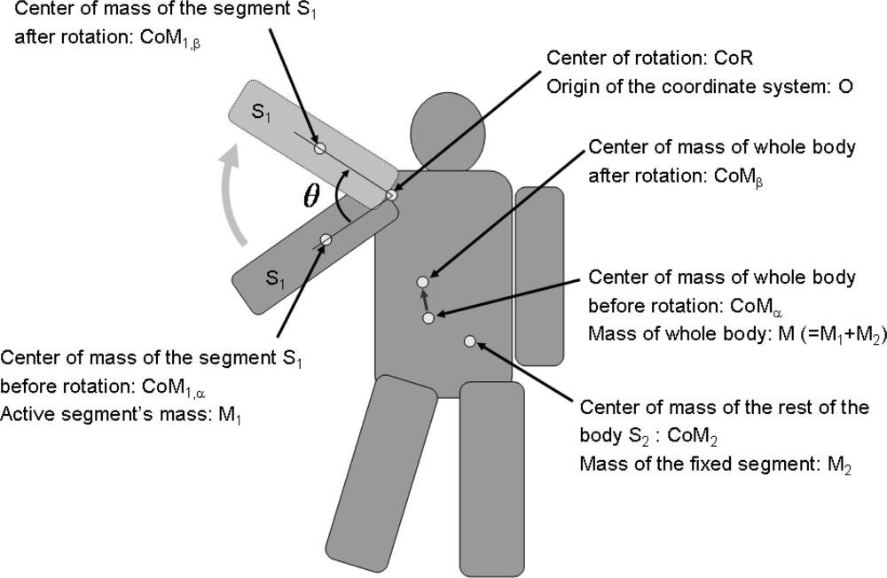
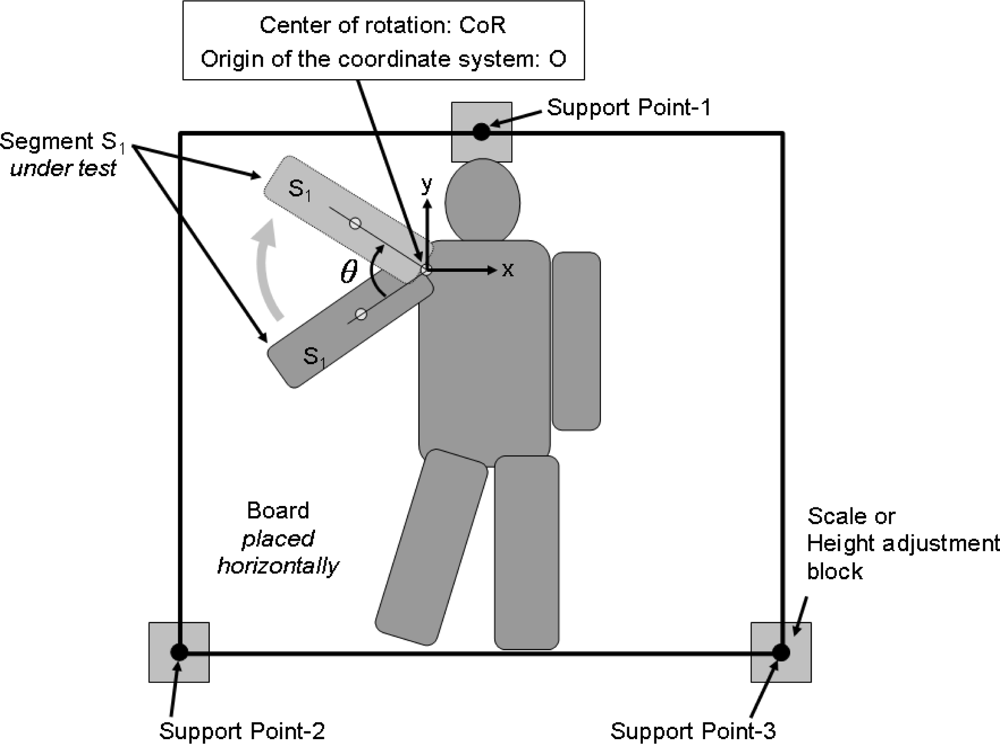
2. Methods
3. Experiment with a Dummy Mass
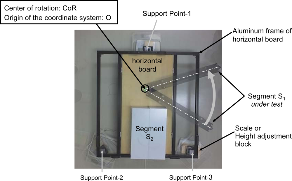
3.1. Experiments
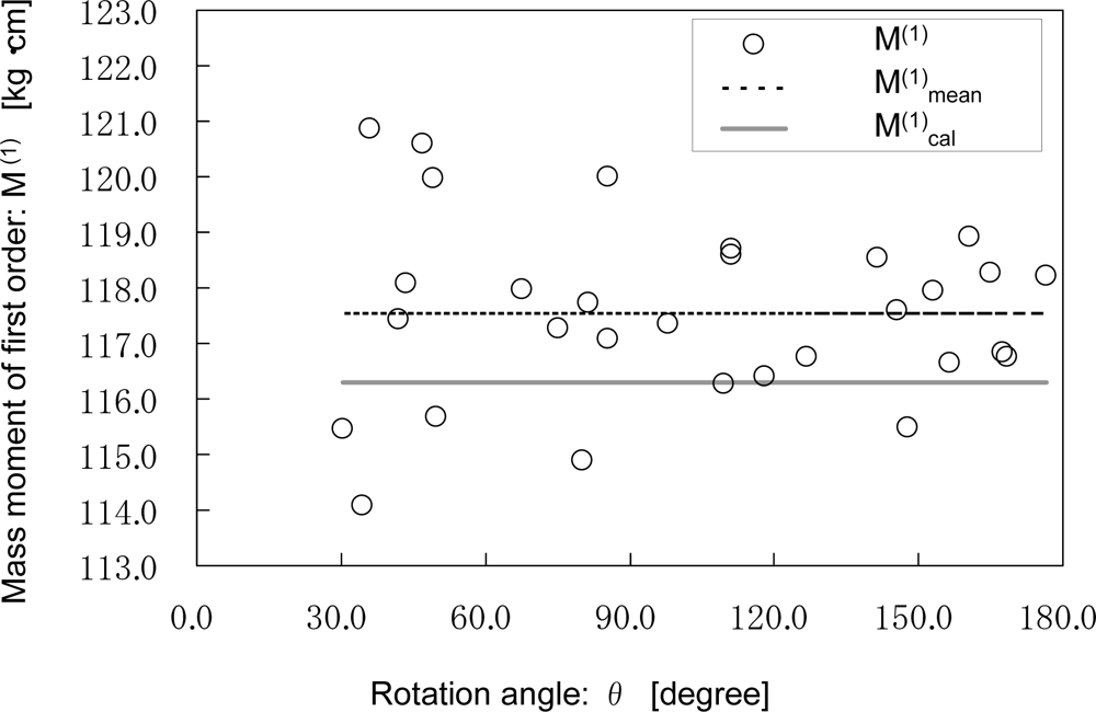
3.2. Results
4. Experiments with a Human Body
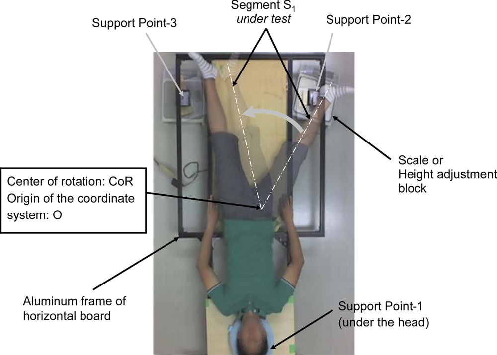
4.1. Experiments
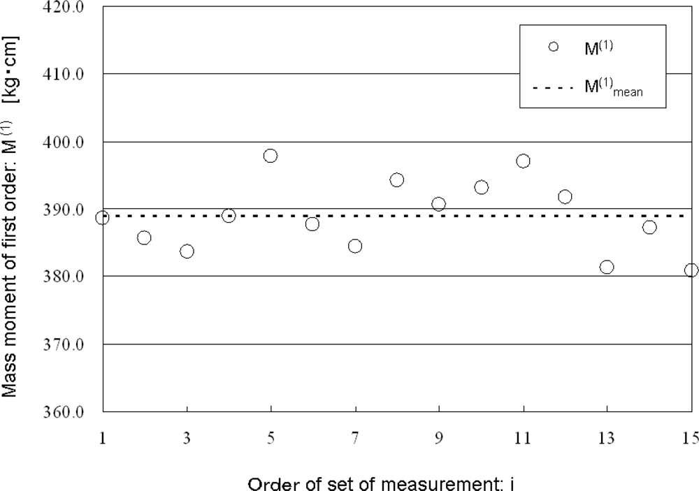
4.2. Results
5. Discussion
6. Conclusions
Acknowledgments
References
- Durkin, JL; Dowling, JJ; Andrews, DM. The measurement of body segment inertia parameters using dual energy X-ray absorptiometry. J. Biomech 2002, 35, 1575–1580. [Google Scholar]
- Durkin, JL; Dowling, JJ; Scholtes, L. using mass distribution information to model the human thigh for body segment parameter estimation. J. Biomech. Eng 2005, 127, 455–464. [Google Scholar]
- Durkin, JL; Dowling, JJ. Body segment parameter estimation of the human lower leg using an elliptical model with validation from DEXA ann. Biomed. Eng 2006, 34, 1483–1493. [Google Scholar]
- Lee, MK; Le, NS; Fang, AC; Koh, MT. Measurement of body segment parameters using dual energy X-ray absorptiometry and three-dimensional geometry: An application in gait analysis. J. Biomech 2009, 42, 217–222. [Google Scholar]
- Davidson, PL; Wilson, SJ; Wilson, BD; Chalmers, DJ. Estimating subject-specific body segment parameters using a 3-dimensional modeller program. J. Biomech 2008, 41, 3506–3510. [Google Scholar]
- Wicke, J; Dumas, GA; Costigan, PA. A comparison between a new model and current models for estimating trunk segment inertial parameters. J. Biomech 2009, 42, 55–60. [Google Scholar]
- Fujii, Y; Shimada, K. Instrument for measuring the mass of an astronaut. Meas. Sci. Technol 2006, 17, 2705–2710. [Google Scholar]
- Fujii, Y; Shimada, K; Maru, K; Yokota, M; Hashimoto, S; Nagai, N; Sugita, Y. Instrument for measuring the body mass of astronaut. Trans Space Sci Jpn 2009, 7, Th_1–Th_6. [Google Scholar]
- Fujii, Y; Shimada, K; Maru, K. Instrument for measuring the body mass of astronauts under microgravity conditions. Microgravity Sci. Technol 2010, 22, 115–121. [Google Scholar]
- Barbier, F; Allard, P; Guelton, K; Colobert, B; Godillon-Maquinghen, A-P. Estimation of the 3-D center of mass excursion from force-plate data during standing. IEEE Trans. Rehab. Eng 2003, 11, 31–37. [Google Scholar]
- McKinon, W; Hartford, C; Zio, L; van Schalkwyk, J; Veliotes, D; Hofmeyr, A; Rogers, G. The agreement between reaction-board measurements and kinematic estimation of adult male human whole body centre of mass location during running. Physiol. Meas 2004, 25, 1339–1359. [Google Scholar]
- Veeger, HEJ. The position of the rotation center of the glenohumeral joint. J. Biomech 2000, 33, 1711–1715. [Google Scholar]
- Koo, S; Andriacchi, TP. The knee joint center of rotation is predominantly on the lateral side during nomal walking. J. Biomech 2008, 41, 1269–1273. [Google Scholar]


© 2010 by the authors; licensee MDPI, Basel, Switzerland. This article is an open access article distributed under the terms and conditions of the Creative Commons Attribution license (http://creativecommons.org/licenses/by/3.0/).
Share and Cite
Fujii, Y.; Shimada, K.; Maru, K.; Ozawa, J.; Lu, R.-S. A Method for Direct Measurement of the First-Order Mass Moments of Human Body Segments. Sensors 2010, 10, 9155-9162. https://doi.org/10.3390/s101009155
Fujii Y, Shimada K, Maru K, Ozawa J, Lu R-S. A Method for Direct Measurement of the First-Order Mass Moments of Human Body Segments. Sensors. 2010; 10(10):9155-9162. https://doi.org/10.3390/s101009155
Chicago/Turabian StyleFujii, Yusaku, Kazuhito Shimada, Koichi Maru, Junichi Ozawa, and Rong-Sheng Lu. 2010. "A Method for Direct Measurement of the First-Order Mass Moments of Human Body Segments" Sensors 10, no. 10: 9155-9162. https://doi.org/10.3390/s101009155