3. Experimental Results
The gaze tracking system was evaluated on a desktop computer with an Intel core 2 quad Q8200 CPU of 2.33 GHz and 4 GB RAM. The images for the experiments were captured using our gaze tracking camera (C600 web-camera, Logitech, Newark, CA, USA) and the image size was 1600 × 1200 pixels [
19]. Two types of filter such as LPF (Wratten Filter No. 89B, Kodak, Rochester, NY, USA) which passes the NIR light whose wavelength is the same as (longer than) 700 nm and BPF (passing range of 850 ± 25 nm) [
20,
21], and two types of halogen lamp [
22,
23] were used for the experiments. Because it is very difficult to obtain the images with sunlight according to the various directions of sunlight, we used high-powered halogen lamps for the experiments.
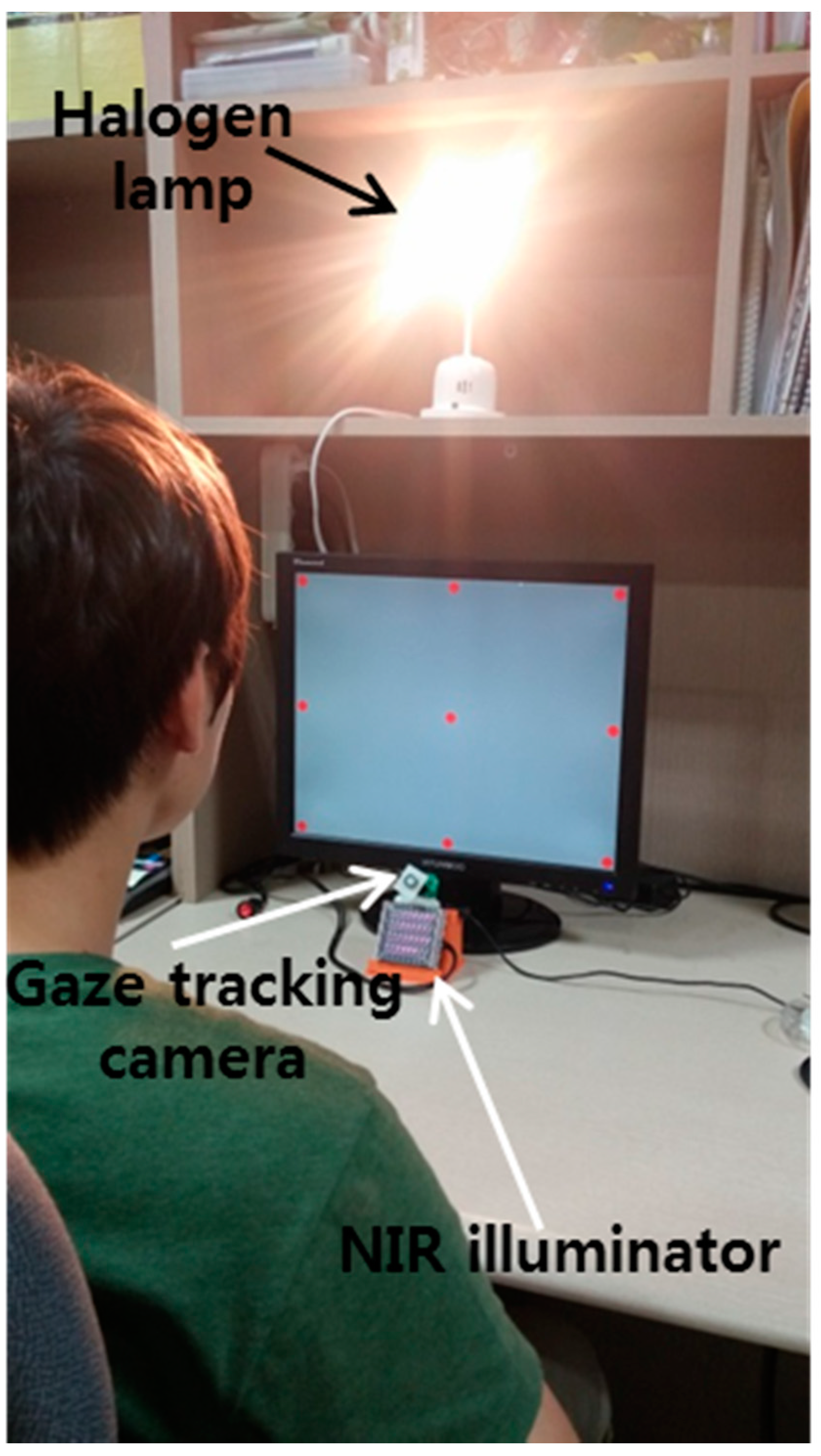
Figure 19 shows our experimental setup for measuring the gaze tracking accuracy under a halogen lamp. The images while 10 people underwent three trials were collected for experiments, and the Z distance between the people and the monitor was about 50~90 cm. A 19-inch monitor with 1280 × 1024 pixels resolution was used for the experiments. Because most gaze tracking systems are used with a desktop (or laptop) computer indoors, we performed our experiments in this environment. As shown in
Figure 20b, we can find that the effect of the imposter SR caused by the halogen lamp can be reduced by using the BPF on the camera, and the genuine SR created by the NIR illuminator can be correctly detected comparing to
Figure 20a.
Figure 19.
Experimental setup for measuring gaze tracking accuracy under a halogen lamp.
Figure 19.
Experimental setup for measuring gaze tracking accuracy under a halogen lamp.
Figure 20.
Resulting images which include the detected pupil and SR under a halogen lamp (a) using LPF (b) using BPF.
Figure 20.
Resulting images which include the detected pupil and SR under a halogen lamp (a) using LPF (b) using BPF.
As the first experiment, we compared the gaze detection error obtained by LPF with that obtained by BPF as shown in
Figure 21. We measured the gaze detection error when each person gazes at nine reference points of
Figure 21. In our research, the gaze detection error is calculated by the difference between each reference point and the calculated one by our gaze detection method. In the left image of
Figure 21, we showed the reference points with the calculated ones by our gaze detection method using BPF and LPF, respectively. In this case, each calculated gaze position is obtained by averaging all the gaze positions calculated from 10 people doing three trials.
Figure 21.
Comparisons of gaze detection errors by LPF and BPF.
Figure 21.
Comparisons of gaze detection errors by LPF and BPF.
The experimental results showed that the gaze detection error using LPF is about 9.52°, which is much larger than that obtained using BPF (about 0.56°). As shown in
Figure 21, we can confirm that the proposed gaze detection system with BPF outperforms that with LPF.
As the second experiment, we measured the gaze detection accuracy with or without the proposed method (removing the region of background external light as shown in
Section 2.2) when a halogen lamp is located behind the user as shown in
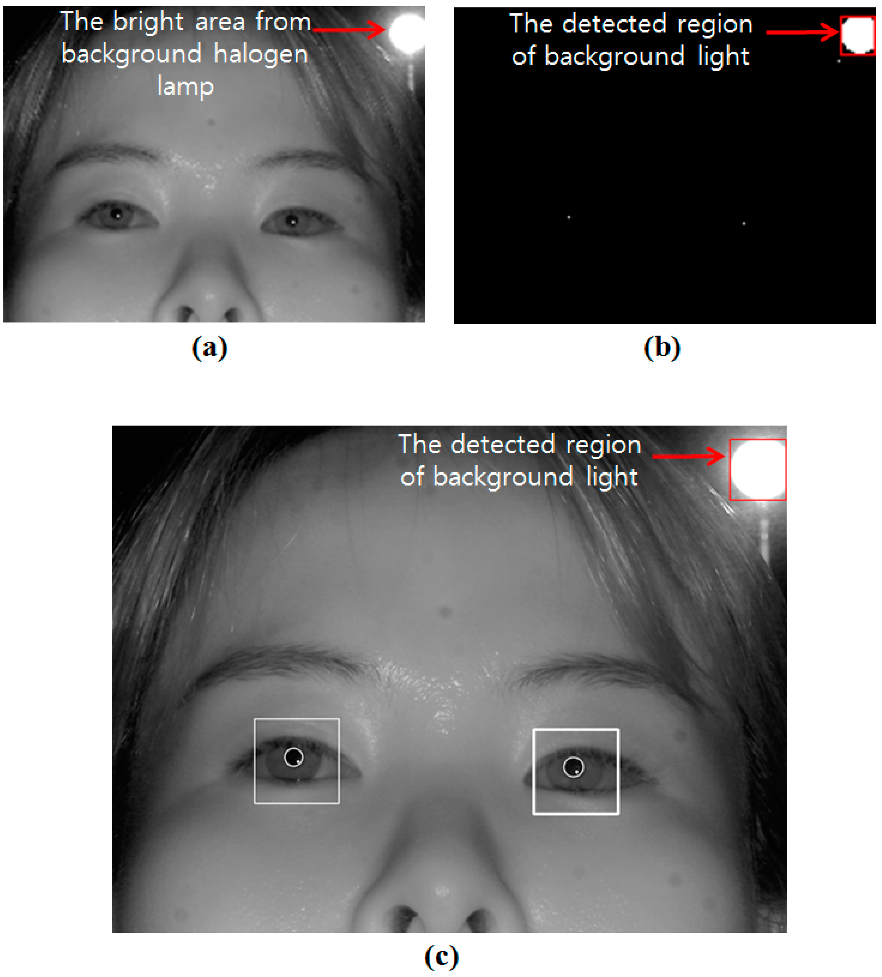
Figure 22. Ten persons performed the test with six trials (three trials when the background external light was positioned on the right based on the person, and the other three trials when it was positioned on the left based on the person). As shown in
Figure 23, we can find that the correct pupil and SR can be detected with our method whereas the incorrect pupil and SR are detected without our method. Because some bright noises can exist around the detected region of background light as shown in
Figure 23b, we increase the region with some margin, and detect the pupil and SR excluding this region.
Figure 22.
Experiments when a halogen lamp is located behind the user.
Figure 22.
Experiments when a halogen lamp is located behind the user.
Figure 23.
Result image of pupil and SR detection (a) not using our method; (b) using our method.
Figure 23.
Result image of pupil and SR detection (a) not using our method; (b) using our method.
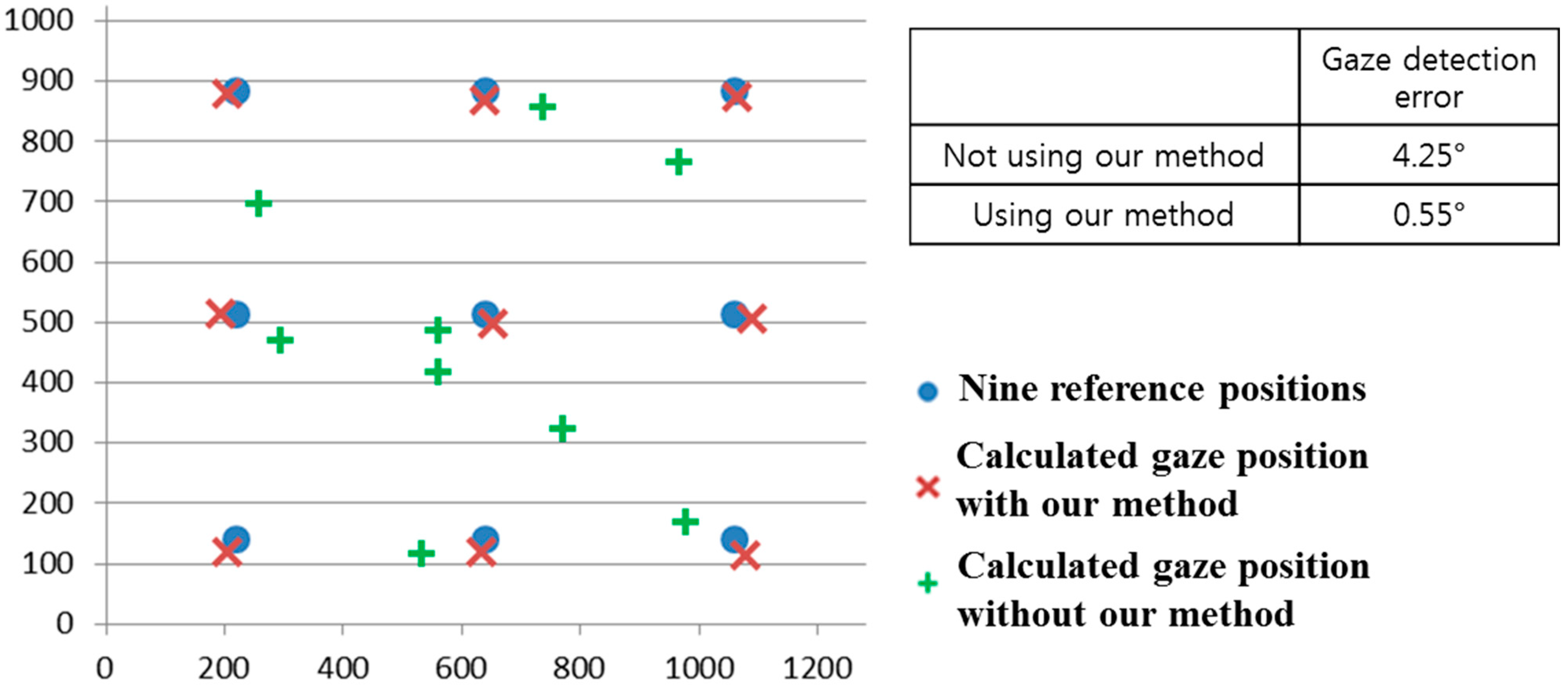
We compared the gaze detection error with and without our method of removing the background external light region as shown in
Figure 24. We measured the gaze detection error when each person gazes at the nine reference points in
Figure 24. In the left image of
Figure 24, we show the reference points, and the calculated ones using and not using our method. In this case, each calculated gaze position is obtained by averaging all the gaze positions calculated from 10 people undergoing three trials. The experimental results showed that the gaze detection error not using our method is about 4.25°, which is much larger than that (about 0.55°) using our method. As shown in
Figure 24, we can confirm that the gaze detection system with our method outperforms that without our method.
Figure 24.
Comparisons of gaze detection errors without and with our method of removing the region of background external light as shown in
Section 2.2.
Figure 24.
Comparisons of gaze detection errors without and with our method of removing the region of background external light as shown in
Section 2.2.
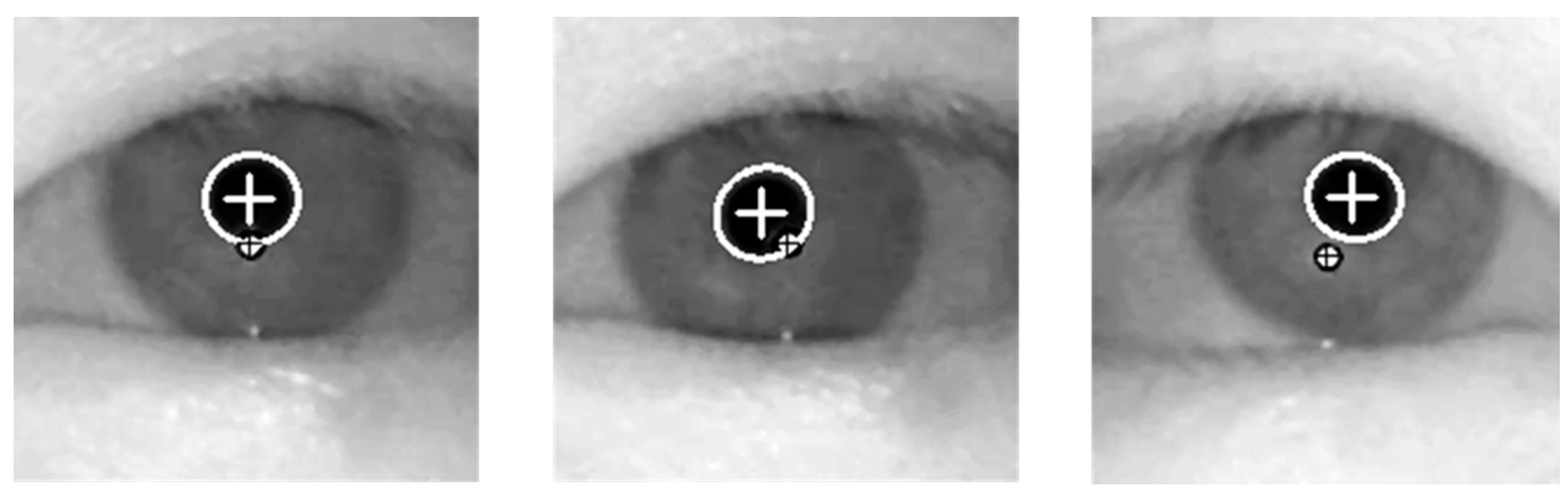
As the next experiment, we compared the gaze detection accuracies with and without our method as described in
Section 2.5. For that, we put the halogen lamp at various positions as shown in
Figure 25. As shown in the resulting images (
Figure 25a–d), we can find that genuine SR can be correctly detected by our method.
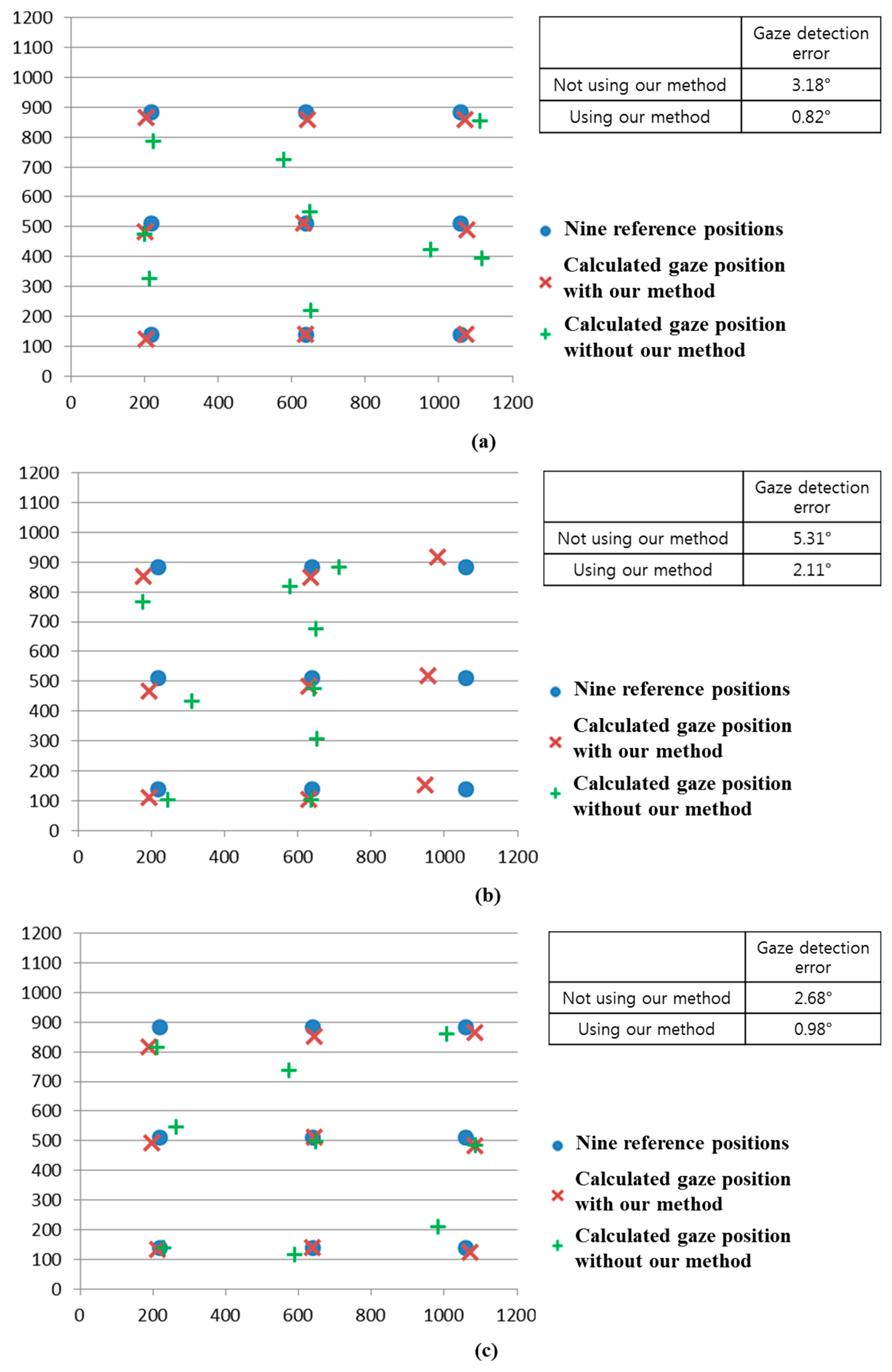
We compared the gaze detection error with and without our method of
Section 2.5 as shown in
Figure 26.
Figure 26a–d shows the gaze detection errors in the cases where the halogen lamp is placed at various positions. Like previous experiments, we measured the gaze detection error when each person gazes at the nine reference points of
Figure 26. In the left images of
Figure 26a–d, we show the reference points and the calculated ones using and not using our method. In these cases, each calculated gaze position is obtained by averaging all the gaze positions calculated from 10 people with three trials. Experimental results showed that the gaze detection errors using our method are much lower than those not using our method, irrespective of the positions of the halogen lamp. Although the gaze detection error with our method is much lower than that without our method, the errors with our method in case of
Figure 26b,d are higher than those of
Figure 26a,c. That is because these cases correspond to the third scenario of
Figure 16, and the errors occur when the pupil center belongs to the common area of GPMA and IPMA.
Figure 25.
Result images where the pupil and SR are correctly detected in the presence of the halogen lamp at various positions (a) above monitor display (b) right of monitor display (c) below monitor display (d) left of monitor display.
Figure 25.
Result images where the pupil and SR are correctly detected in the presence of the halogen lamp at various positions (a) above monitor display (b) right of monitor display (c) below monitor display (d) left of monitor display.
Figure 26.
Comparisons of gaze detection errors without and with our method of
Section 2.5 in case of the halogen lamp (
a) above monitor display; (
b) right of monitor display; (
c) below monitor display; (
d) left of monitor display.
Figure 26.
Comparisons of gaze detection errors without and with our method of
Section 2.5 in case of the halogen lamp (
a) above monitor display; (
b) right of monitor display; (
c) below monitor display; (
d) left of monitor display.
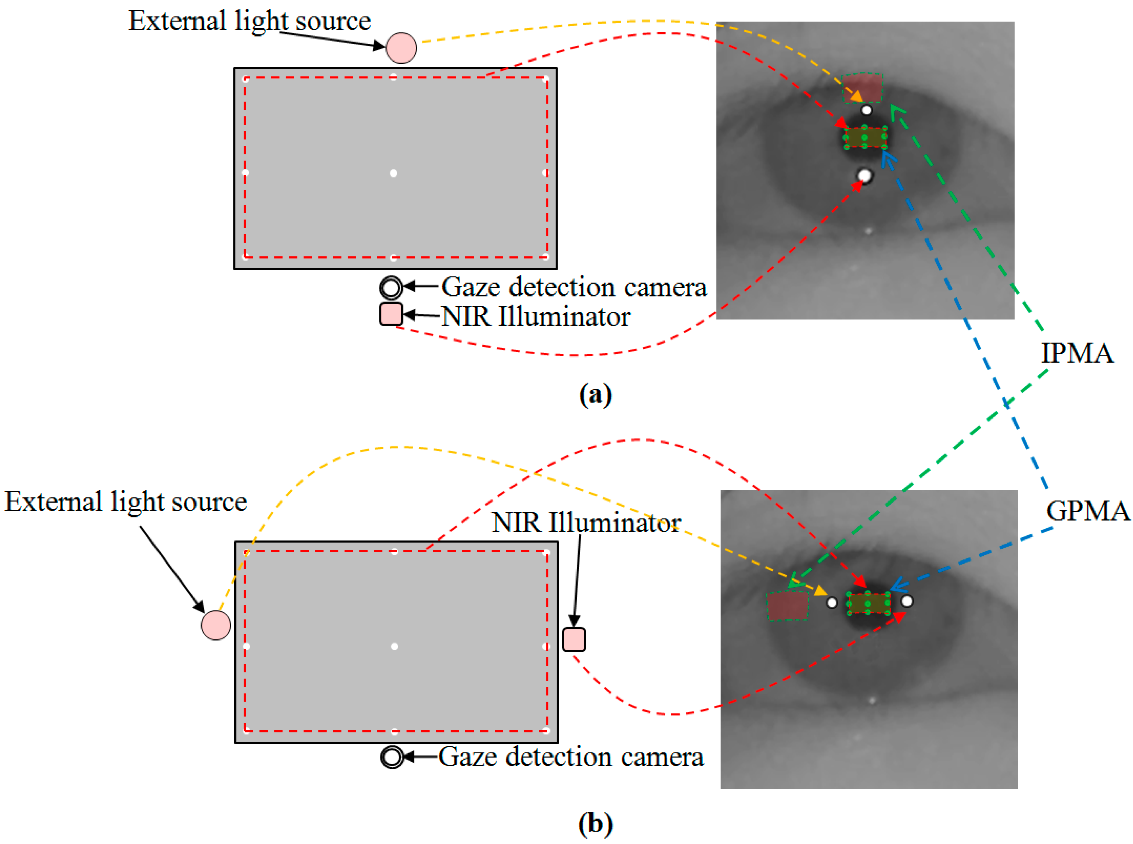
As shown in
Figure 16a, the common area has the characteristic that it exists in the right part of GPMA when the external light is positioned in the right based on the NIR illuminator. In addition, as shown in
Figure 16b, the common area has the characteristic of being in the left part of GPMA when the external light is positioned in the left based on the NIR illuminator. Because the halogen lamp was positioned in the right based on the NIR illuminator in case of
Figure 25b, this corresponds to the case of
Figure 16a, and the resulting common area exists in the right part of GPMA. From this, we can know that the errors occur when the user gazes at the right reference positions (in this case, the probability of pupil center belonging to the common area increases because the common area is in the right part of GPMA) as shown in
Figure 26b.
Like these, because the halogen lamp was positioned in the left based on the NIR illuminator in case of
Figure 25d, this corresponds to the case of
Figure 16b, and the resulting common area exists in the left part of GPMA. From this, we can know that the errors occur when the user gazes at the left reference positions (in this case, the probability of pupil center belonging to the common area increases because the common area is in the left part of GPMA) as shown in
Figure 26d. In conclusion, we can confirm from the above experimental results that our gaze detection system is robust to the external light placement at various positions.
We performed additional experiments where the presence of reflections in the user’s iris can occur due to window frames or glasses. As shown in
Figure 27a, three experiments were done. The first case is when sunlight is positioned in the left side of user’s face as shown in the left image of
Figure 27a. The second case is when the sunlight is positioned in front of user’s face as shown in the middle image of
Figure 27a. The third one is when the sunlight is positioned in the right side of user’s face as shown in the right image of
Figure 27a.
Figure 27.
Comparative experiments in various positions of sunlight relative to user’s face. (a) the left, middle, and right images show the cases when sunlight is positioned in the left side, front, and right side of user’s face, respectively; (b) the captured eye image of the case of left image of (a) with BPF; (c) the captured eye image of the case of middle image of (a) with BPF; (d) the captured eye image of the case of right image of (a) with BPF; (e) the captured eye image of the case of left image of (a) with LPF; (f) the captured eye image of the case of middle image of (a) with LPF; (g) the captured eye image of the case of right image of (a) with LPF.
Figure 27b–d represents the captured eye images of the cases of the left, middle, and right images of
Figure 27a with BPF, respectively. As shown in
Figure 27b–d, we can find that there is no reflection caused by the window frames or glasses in the user’s iris. This is because our system uses a 850 nm NIR light illuminator and the camera attached by a BPF (passing range of 850 ± 25 nm) [
20,
21]. Therefore, most of transmitted light to the camera of our system is that of NIR illuminator (850 nm) of our gaze detection system, and other light of different wavelengths in addition to the reflections caused by window frames or glasses can be blocked out by the BPF of our system.
For comparison, we show the eye images captured with LPF.
Figure 27e–g represents the captured eye images of the cases of the left, middle, and right images of
Figure 27a with LPF, respectively. As shown in
Figure 27e–g, we can find that there exist reflections produced by the window frames or glasses in the user’s iris when the LPF which passes the NIR light whose wavelength is same as (longer than) 700 nm is used in our gaze detection system. From these, we can find that the reflections produced by window frames or glasses can be blocked out by the BPF of our system. We include the experimental results of the percentage of correctly labeled image of genuine SR
versus total number of image in the four cases (
Figure 25a–d) as shown in
Table 2.
Table 2.
The percentage of correctly labeled image of genuine SR
versus total number of image in the four cases (
Figure 25a–d, unit: %).
As shown in
Table 2, the average percentage of correctly labeled images of genuine SR
versus total number of images is higher than 95%. In
Table 2, the percentages in the cases of
Figure 25b,d are lower than those of
Figure 25a,c. That is because these cases of
Figure 25b,d correspond to the third scenario of
Figure 16, and the errors occur when the pupil center belongs to the common area of GPMA and IPMA.
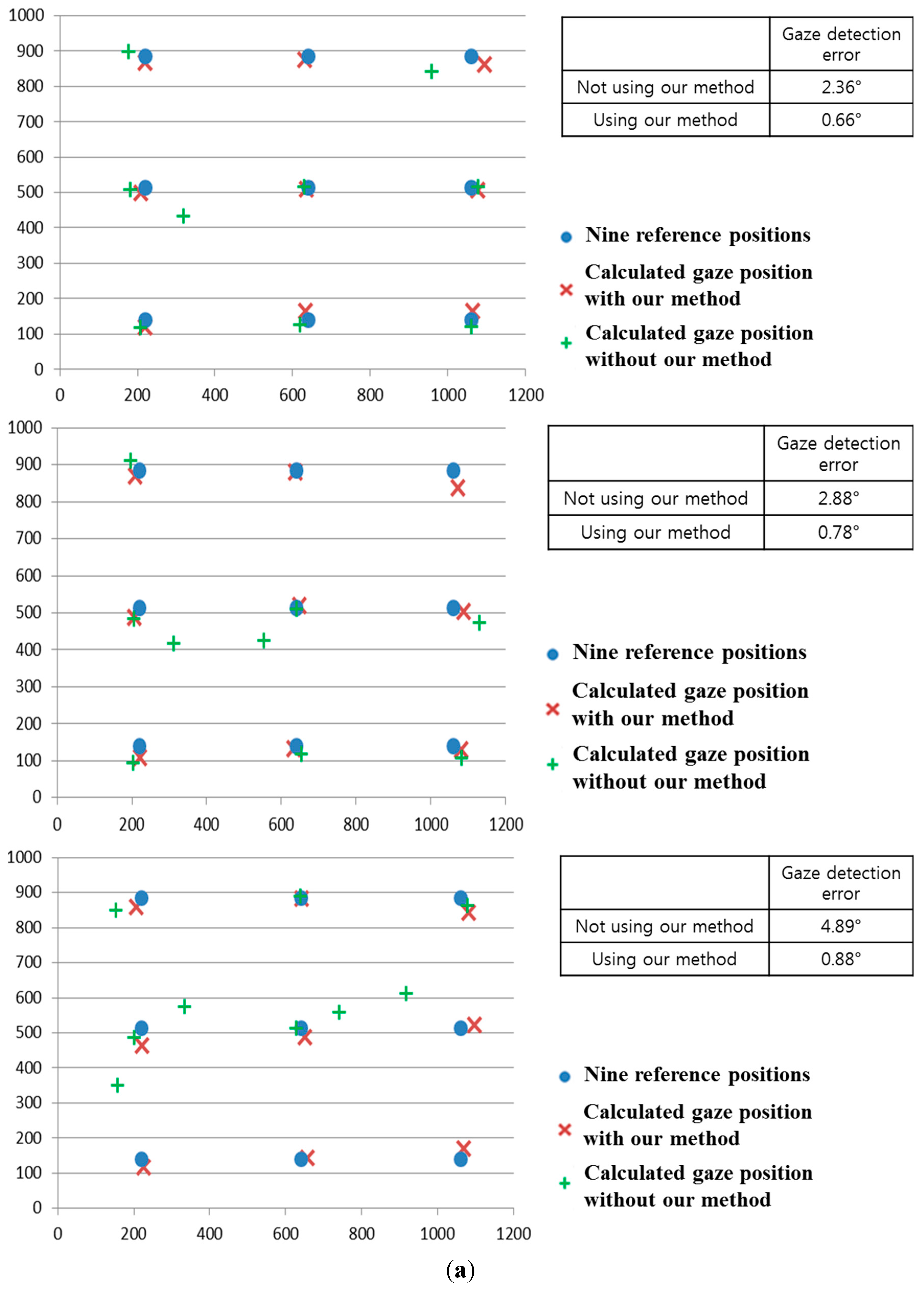
As the next experiment, we performed additional experiments with five people wearing glasses.
Figure 28 shows the examples of users wearing glasses. Results are shown in
Figure 29 and
Table 3. Like the previous experiments of
Figure 24 and
Figure 26, we measured the gaze detection error when each person gazes at the nine reference points of
Figure 29. In these cases, each calculated gaze position is obtained by averaging all the gaze positions calculated from five people. As shown in
Figure 29, the gaze detection errors with people wearing glasses were almost similar to those with people not wearing glasses of
Figure 26.
In addition, we include the experimental results of the percentage of correctly labeled images of genuine SR
versus total number of image in the four cases (
Figure 29a–d) as shown in
Table 3, where the average percentage of correctly labeled image of genuine SR
versus total number of images is higher than 96%, which is similar to that with people without glasses of
Table 2. From
Figure 29 and
Table 3, we can find that the performance of our system is not affected by people wearing glasses.
Figure 28.
Examples of users wearing glasses. (a) user 1 with the halogen lamp above monitor display; (b) user 2 with the halogen lamp at the right of monitor display; (c) user 3 with the halogen lamp at the left of monitor display; (d) user 4 with the halogen lamp below monitor display.
Figure 28.
Examples of users wearing glasses. (a) user 1 with the halogen lamp above monitor display; (b) user 2 with the halogen lamp at the right of monitor display; (c) user 3 with the halogen lamp at the left of monitor display; (d) user 4 with the halogen lamp below monitor display.
Table 3.
The percentage of correctly labeled image of genuine SR versus total number of image in case of five people wearing glasses (unit: %).
Table 3.
The percentage of correctly labeled image of genuine SR versus total number of image in case of five people wearing glasses (unit: %).
| Case | Percentage |
|---|
| Figure 29a | 100 |
| Figure 29b | 93.33 |
| Figure 29c | 100 |
| Figure 29d | 91.11 |
| Average | 96.11 |
Although the gaze detection error with our method is much lower than that without our method in
Figure 29a–d, the errors with our method in case of
Figure 29b,d are higher than those of
Figure 29a,c. In addition, the percentages of correctly labeled image of genuine SR
versus total number of image in case of
Figure 29b,d are lower than those of
Figure 29a,c in
Table 3. That is because these cases of
Figure 29b,d correspond to the third scenario of
Figure 16, and the errors occur when the pupil center belongs to the common area of GPMA and IPMA.
Figure 29.
Comparisons of gaze detection errors with five people wearing glasses without and with our method of
Section 2.5 in the presence of the halogen lamp at various positions (like
Figure 25) (
a) above monitor display; (
b) right of monitor display; (
c) below monitor display; (
d) left of monitor display.
Because it is difficult to obtain the images with sunlight in various positions, we have experimented with halogen illuminators placed in various positions as shown in
Figure 25. Our system uses an 850 nm NIR light illuminator and the camera is equipped with a BPF (passing range of 850 ± 25 nm) [
20,
21], which makes the wavelength of most of the light transmitted to the camera of our system be within the range around 850 nm. In addition, when we compared the power of the halogen illuminators and sunlight in the wavelength range around 850 nm, they are similar. From that, we can conclude that the effect of sunlight is expected to be similar to that of the halogen illuminators.
To prove this, we performed additional experiments using various sunlight positions relative to the user’s face (as shown in
Figure 27). As shown in
Figure 30 and
Table 4, the results (gaze detection error and the percentage of correctly labeled image of genuine SR
versus total number of image) from five people are similar to those of
Figure 25 and
Table 2. From that, we can find that the performance of our system is not affected by the various positions of sunlight.
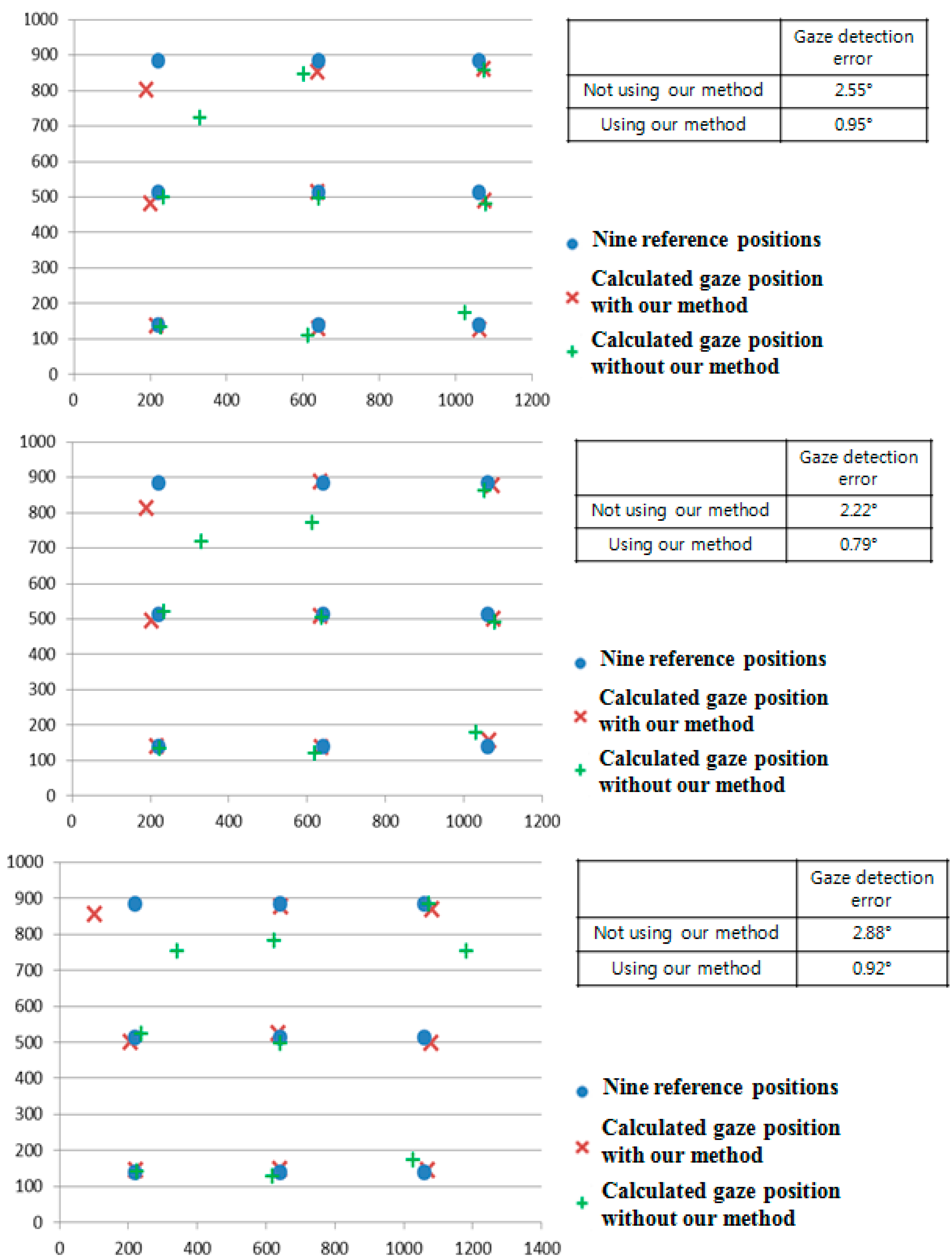
As the next experiment, we performed additional tests with five people performing various head rotations and translations as shown in
Figure 31. Like the previous experiments shown in
Figure 24,
Figure 26,
Figure 29 and
Figure 30, we measured the gaze detection error when each person gazed at nine reference points (
Figure 32). In these cases, each calculated gaze position is obtained by averaging all the gaze positions calculated from the five people. In detail, each people naturally rotated his head five times based on the X, Y, and Z axes, respectively, within an angular range of about −10°~+10°. This angular range is determined considering the case when a user naturally looks at any position of the monitor with head rotation. In addition, each person naturally translated his head five times in the directions of X, Y, and Z axes, respectively, within the translational range of about –4~+4 cm. This translational range is also determined considering the case when a user naturally looks at any position of the monitor with head translation.
Figure 30.
Comparisons of gaze detection errors without and with our method of
Section 2.5 in various positions of sunlight relative to user’s face (
a) when sunlight is positioned in front of user’s face; (
b) when sunlight is positioned in the right side of user’s face; (
c) when sunlight is positioned in the left side of user’s face.
Table 4.
The percentage of correctly labeled image of genuine SR versus total number of image in case of sunlight (unit: %).
Table 4.
The percentage of correctly labeled image of genuine SR versus total number of image in case of sunlight (unit: %).
| Case | Percentage |
|---|
| Figure 30a | 100 |
| Figure 30b | 100 |
| Figure 30c | 100 |
| Average | 100 |
Figure 31.
Head rotation and translation in our experiments.
Figure 31.
Head rotation and translation in our experiments.
In each case, we performed the experiments with the halogen lamp in four positions (above, right, below, and left of monitor display) while each people looked at the nine reference positions to measure the accuracy of gaze detection as shown in
Figure 32. Therefore, we obtained the 5400 images of (5 people × 6 head movements (3 rotations and 3 translations) × 4 positions of halogen lamp × 9 images (image where a user gazed at one of the nine reference positions of monitor) × 5 trials) for measuring the accuracies.
As shown in
Figure 32, the gaze detection errors with people performing various head rotations and translations were almost similar to those with people not performing head rotations and translations (
Figure 26).
In addition, we include the experimental results of the percentage of correctly labeled images of genuine SR
versus total number of image in the twenty four cases (
Figure 32a–d) as shown in
Table 5. As shown in
Table 5, the average percentage of correctly labeled image of genuine SR
versus total number of image is higher than 95%, which is similar to that with people not having head rotations and translations of
Table 2. From the
Figure 32 and
Table 5, we can find that the performance of our system is not affected by head rotations or translations.
Figure 32.
Comparisons of gaze detection errors with five people having various head rotations and translations without and with our method of
Section 2.5 in the presence of the halogen lamp at various positions (like
Figure 25). (
a) above monitor display; (
b) right of monitor display; (
c) below monitor display; (
d) left of monitor display (In the
Figure 29a–d, the 1st–6th Figures represent the cases of head rotations in X, Y, Z axes, and head translations in X, Y, Z axes of
Figure 31, respectively).
Table 5.
The percentage of correctly labeled image of genuine SR versus total number of image in case of head rotations and translations (unit: %).
Table 5.
The percentage of correctly labeled image of genuine SR versus total number of image in case of head rotations and translations (unit: %).
| Case | Percentage |
|---|
| Figure 32a | 1st Figure | 100 |
| 2nd Figure | 100 |
| 3rd Figure | 100 |
| 4th Figure | 100 |
| 5th Figure | 100 |
| 6th Figure | 100 |
| Figure 32b | 1st Figure | 91.11 |
| 2nd Figure | 91.11 |
| 3rd Figure | 93.33 |
| 4th Figure | 91.11 |
| 5th Figure | 91.11 |
| 6th Figure | 91.11 |
| Figure 32c | 1st Figure | 100 |
| 2nd Figure | 100 |
| 3rd Figure | 100 |
| 4th Figure | 100 |
| 5th Figure | 100 |
| 6th Figure | 100 |
| Figure 32d | 1st Figure | 91.11 |
| 2nd Figure | 93.33 |
| 3rd Figure | 91.11 |
| 4th Figure | 91.11 |
| 5th Figure | 91.11 |
| 6th Figure | 91.11 |
| | Average | 95.74 |
As shown in
Figure 14,
Figure 15 and
Figure 16 and Equations (1) and (2), discrimination between the correct SR and the imposter SR was possible by verifying the relationship between the corneal SR and the pupil movable area with the relative position of the pupil and the corneal SR.
In the cases of head rotations and translations, the direction and amount of movement of the correct SR are almost same to those of the imposter SR in the image, as shown in
Figure 33. Therefore, the relative positions among the correct SR, the imposter SR, and pupil center are maintained in case of gazing at same position even with head rotations and translations as shown in
Figure 33. Consequently, the relationships among GPMA, IPMA, correct SR, and imposter SR (
Figure 14,
Figure 15 and
Figure 16) are almost maintained before and after head movement as shown in
Figure 33. Therefore, the performance of our system is not affected by head rotations and translations as shown in
Figure 32 and
Table 5.
Figure 33.
The examples of relationships among GPMA, IPMA, correct SR, and imposter SR in case of head rotations and translations while gazing at same position. The directions of rotations and translations are shown in
Figure 31. In each eye image of Figure of (
a)~(
g), upper and lower SRs are imposter and correct SRs, respectively. (
a) before head movement; (
b) head rotation in X axis; (
c) head rotation in Y axis; (
d) head rotation in Z axis; (
e) head translation in X axis; (
f) head translation in Y axis; (
g) head translation in Z axis.
In previous research, the adaptive boosting (AdaBoost) detector has been widely used for eye ROI detection [
24]. However, the AdaBoost detector can only locate the rough position of eye ROI (like Step 3 of
Figure 1). Therefore, the accurate pupil center and corneal SR center should be detected by our method (explained in
Section 2.3) in order to calculate the gaze position. As the next experiment, we compared the performances of eye ROI detection by the AdaBoost detector, another statistical continuously adaptive mean shift (Camshift) method [
25], and our method with the data of
Figure 25,
Figure 29 and
Figure 30. As shown in
Table 6, the accuracies of eye ROI detection by AdaBoost or the Camshift detector are lower than that by our method. In addition, the processing time of eye ROI detection by AdaBoost or Camshift detector is higher than that of our method (17 ms). From that, we can conclude that our method outperforms these other methods.
Table 6.
Comparisons of the accuracies and processing time of eye ROI detection by AdaBoost, Camshift, and our method.
Table 6.
Comparisons of the accuracies and processing time of eye ROI detection by AdaBoost, Camshift, and our method.
| Method | Accuracy (%) | Processing Time (ms) |
|---|
| AdaBoost method | 96.25 | 104.985 |
| Camshift method | 99.5 | 45.8675 |
| Our method | 100 | 17 |
As the last experiment, we measured the processing time of our method (according to the steps of
Figure 1) as shown in
Table 7. From the experimental results, we can know that our system can be operated at the fast speed of approximately 19 (1000/53) frames/sec.
Table 7.
Processing time of our method (unit: ms).
Table 7.
Processing time of our method (unit: ms).
| Steps | Processing Time |
|---|
| Detect the largest area by external light | 1 |
| Detect the eye ROI | 16 |
| Find the threshold value for binarization of pupil | 16 |
| Detect SR and pupil | 20 |
| Discriminate genuine SR from imposter one by external light | 0 |
| Calculate gaze position | 0 |
| Total | 53 |


