Article

Modelling of XCO2 Surfaces Based on Flight Tests of TanSat Instruments

1
State Key Laboratory of Resources and Environment Information System, Institute of Geographical Sciences and Natural Resources Research, Chinese Academy of Sciences, Beijing 100101, China
2
Spatial Sciences Institute, Dana and David Dornsife College of Letters, Arts, and Sciences, University of Southern California, Los Angeles, CA 90089-0374, USA
3
Ministry of Education Key Laboratory for Nonequilibrium Synthesis and Modulation of Condensed Matter, School of Science, Xi’an Jiaotong University, Xi’an 710049, China
4
Changchun Institute of Optics, Fine Mechanics and Physics, Chinese Academy of Sciences, Changchun 130033, China
*
Author to whom correspondence should be addressed.
Sensors 2016, 16(11), 1818; https://doi.org/10.3390/s16111818
Submission received: 16 August 2016 / Revised: 25 October 2016 / Accepted: 26 October 2016 / Published: 1 November 2016
(This article belongs to the Section Remote Sensors)

Abstract

:
The TanSat carbon satellite is to be launched at the end of 2016. In order to verify the performance of its instruments, a flight test of TanSat instruments was conducted in Jilin Province in September, 2015. The flight test area covered a total area of about 11,000 km2 and the underlying surface cover included several lakes, forest land, grassland, wetland, farmland, a thermal power plant and numerous cities and villages. We modeled the column-average dry-air mole fraction of atmospheric carbon dioxide (XCO2) surface based on flight test data which measured the near- and short-wave infrared (NIR) reflected solar radiation in the absorption bands at around 760 and 1610 nm. However, it is difficult to directly analyze the spatial distribution of XCO2 in the flight area using the limited flight test data and the approximate surface of XCO2, which was obtained by regression modeling, which is not very accurate either. We therefore used the high accuracy surface modeling (HASM) platform to fill the gaps where there is no information on XCO2 in the flight test area, which takes the approximate surface of XCO2 as its driving field and the XCO2 observations retrieved from the flight test as its optimum control constraints. High accuracy surfaces of XCO2 were constructed with HASM based on the flight’s observations. The results showed that the mean XCO2 in the flight test area is about 400 ppm and that XCO2 over urban areas is much higher than in other places. Compared with OCO-2’s XCO2, the mean difference is 0.7 ppm and the standard deviation is 0.95 ppm. Therefore, the modelling of the XCO2 surface based on the flight test of the TanSat instruments fell within an expected and acceptable range.

1. Introduction

Atmospheric carbon dioxide (CO2) is the dominant anthropogenic greenhouse gas, and a crucial factor in global climate change [1]. However, our current knowledge about the temporal and spatial variability of atmospheric CO2 is still insufficient, which leads to large uncertainties in our estimates of carbon sources and sinks [2,3,4]. Ground-based observations, for example, are accurate but too spatially sparse to sufficiently infer CO2 sources and sinks [3,5,6,7,8,9]. Space-based measurements, on the other hand, have the potential to yield global estimates of the distribution of the atmospheric CO2 vertical column (in molecules/cm2) or the CO2 dry air column-averaged mole fraction (in ppm), especially in areas not covered by ground-based observations [5,10].
Near and short-wave infrared (NIR) measurements have sufficiently high precision and sensitivity to the planetary boundary layer, where the largest signals of sources and sinks occur [2,3,6,7,11,12,13,14,15,16]. The first NIR carbon satellite instrument, SCIAMACHY, onboard ENVISAT that was launched in 2002 and lost in 2012, measured reflected solar radiation in the NIR spectral bands [4,9]. Presently, there are only two NIR carbon satellite instruments orbiting the Earth, which enable the retrieval of XCO2 with significant sensitivity in the boundary layer (i.e., near the Earth’s surface). The two instruments are TANSO, onboard GOSAT launched in 2009 and OCO-2 launched in 2014 [12,13,14]. China’s first satellite to monitor atmospheric XCO2, TanSat, will be launched at the end of 2016. A flight test was conducted in September, 2015 to evaluate the performance and stability of TanSat’s instruments for acquiring high resolution absorption spectra, and to reduce the risk of TanSat operating problems after launch. Simultaneous ground-based measurements of geophysical parameters were also collected and can be used to evaluate the accuracy of the retrieved atmospheric XCO2 estimates.
The remainder of this article is structured as follows: Section 2 introduces the flight area and data used in this article. Section 3 introduces the methods used in this study, including the deployment of a full physics retrieval algorithm to retrieve XCO2 in the flight test area, the use of regression modeling to estimate the approximate XCO2 surface, and the use of the HASM platform to model the XCO2 surface. Section 4 analyzes the retrieval results and distribution of XCO2 in the flight test area. Section 5 concludes the paper and discusses future work.

2. Study Area and Data

2.1. Flight Logistics and Data

TanSat aims to deliver XCO2 in ppm at a high spatial resolution in square grids measuring 3 km on a side. An evaluation of the performance of the TanSat imaging spectrometer prototype was conducted as part of flight tests on the 11th, 14th and 16th of September, 2015. The flight demand parameters, such as the flight height, flight speed, flight time, solar zenith angle, flight geometric requirements and meteorological conditions, can be seen in Table 1.
The flight’s spectrometer covered two of the three NIR spectral bands that will be included in the final TanSat spectrometer (Table 2). We can see that band 1 observed the O2 A-band spectral region (758–773 nm) at 0.044 nm spectral resolution and that Band 2 covers the 1592–1625 nm spectral region with a spectral resolution of 0.13 nm. The third TanSat spectral band (2060 nm), which will provide CO2 absorption and water vapour information, was not included in the prototype and flight test due to cost.
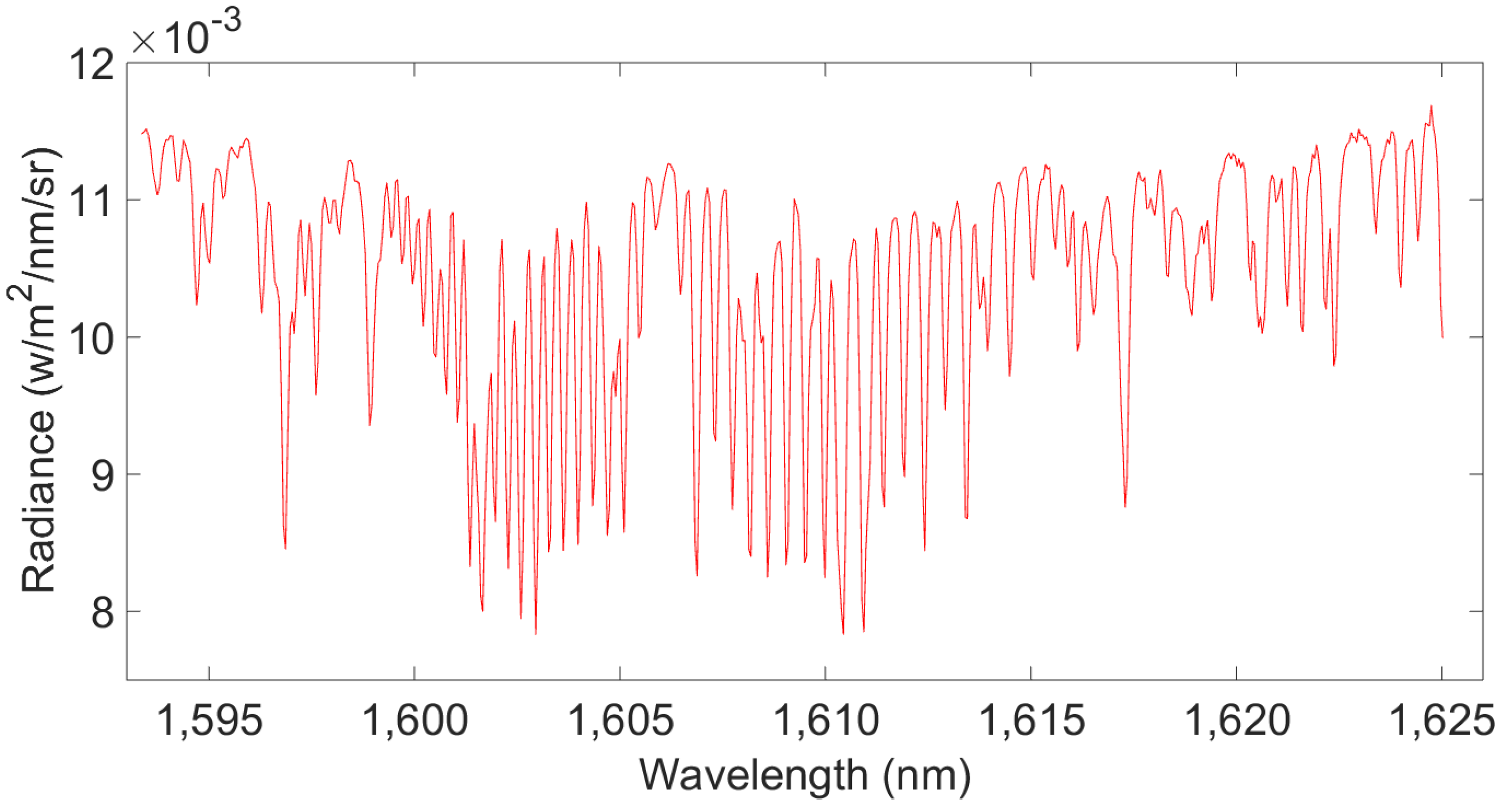
For this study, we acquired the flight test’s L1B data (calibrated and geographically located spectral radiances) from the Changchun Institute of Optics, Fine Mechanics and Physics, Chinese Academy of Sciences. They had processed the dark background and calibrated the spectral radiation for the test flight’s L1A DN (digital number) data. Samples of two NIR spectral bands derived from the L1B data used in the study can be seen in Figure 1 and Figure 2. The X-axis shows spectral wavelengths (in nm), and the Y-axis represents the spectral radiance (in W/m2/nm/sr). Band 1 contains O2 absorption information and can be used to estimate the O2 column with high near-surface sensitivity. Similarly, band 2 contains CO2 weak absorption information and can be used to estimate the CO2 column with high near-surface sensitivity.

2.2. Study Area and Surface Characteristics

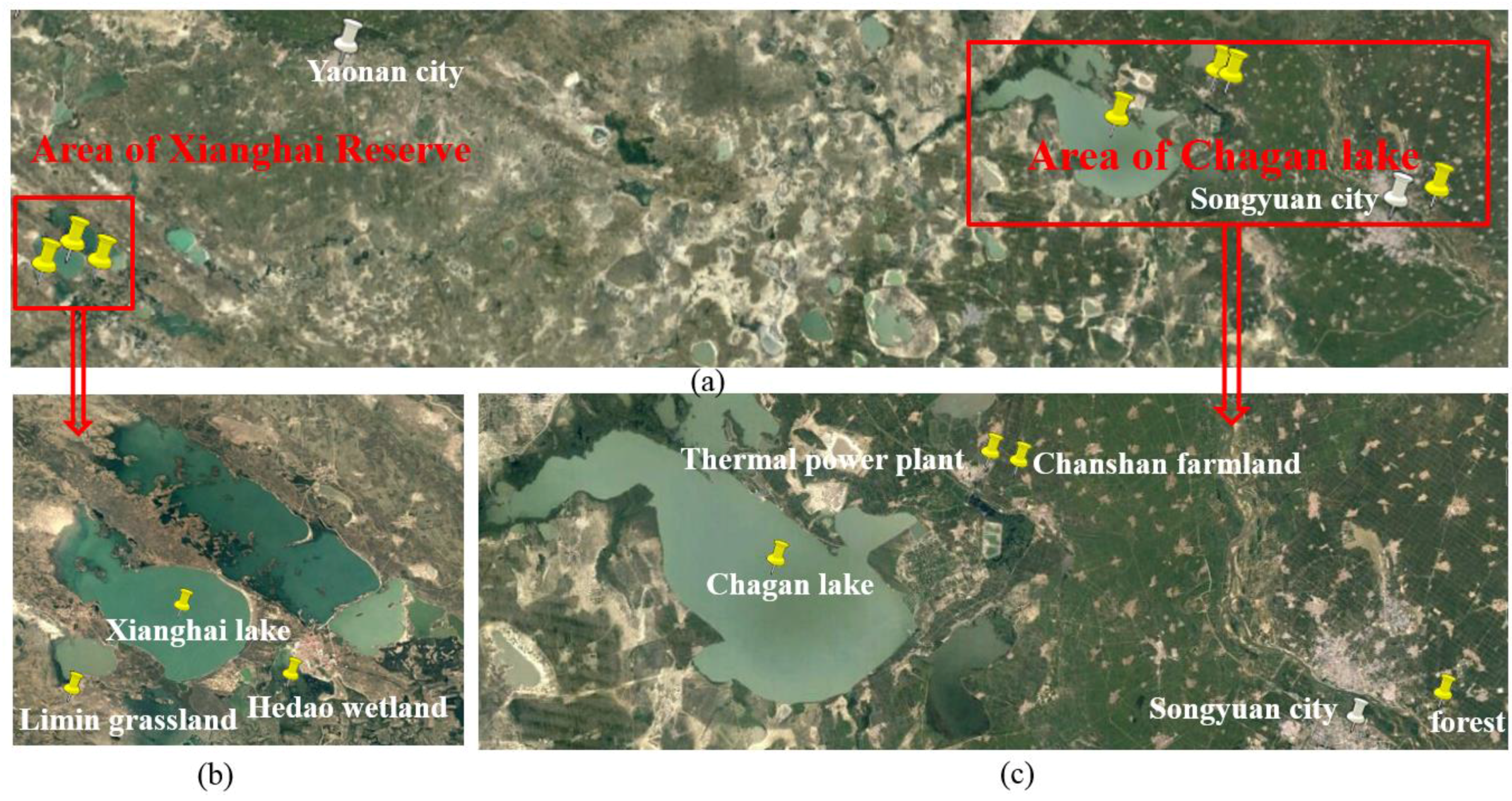
The flight test passed over Xianghai Reserve and Chagan Lake in Jilin Province (Figure 3). The underlying surface included several lakes, forest, grass, and wetlands, farmland, a thermal power plant and numerous cities and villages. The test area runs from 122.205° E to 124.946° E and from 44.980° N to 45.360° N and cover an area of about 11,000 km2. The left red box of Figure 3 covers the Xianghai Reserve and includes the Limin grassland, Hedao wetland and Xianghai Lake. The right red box of Figure 3 shows the Chagan Lake area and includes the Chanshan town thermal power plant, farmland, Chagan Lake and Songyuan City.
Ground synchronous observations were also collected during the flight period, and provided important auxiliary data for XCO2 retrieval and simulation in the flight test area. The observations and methods used to gather them are listed in Table 3. Temperature, humidity, pressure and wind profiles were obtained by sonde measurements and used to summarize the state of the atmosphere for XCO2 retrieval and surface estimation (Table 3). The CO2 concentration at the surface was observed with a Greenhouse gas online laser analyzer. The CO2 profile gathered with a captive balloon and CO2 concentration in the surface layer were used as dependent variables in the flight test area when we established the approximate XCO2 surface. Aerosol optical depth and surface reflectance are also crucial factors for XCO2 retrieval and were observed with a sun photometer and ASD spectrometer, respectively.

3. Methods

We first retrieved the XCO2 using a full physics retrieval algorithm. However, it is difficult to directly analyze the spatial distribution of XCO2 in the flight test area using the limited retrieval results. The high accuracy surface modeling (HASM) method has been widely used in the simulation of climate change, CO2 concentrations in the surface layer, and terrestrial land cover change [17,18,19]. We therefore used HASM to fill the gaps where there was no information on XCO2 in the flight test area. The entire workflow reproduced in Figure 4 includes three main steps. First, we used a full physics retrieval algorithm to retrieve XCO2. Second, we used regression modeling to establish the approximate (i.e., not very accurate) surface of XCO2 in the flight test area. And third, we used HASM, which took the approximate surface of XCO2 as its driving field and retrieved XCO2 as its optimum control constraints, to simulate a high accuracy XCO2 surface for the whole flight test area.

3.1. Retrieval Algorithm

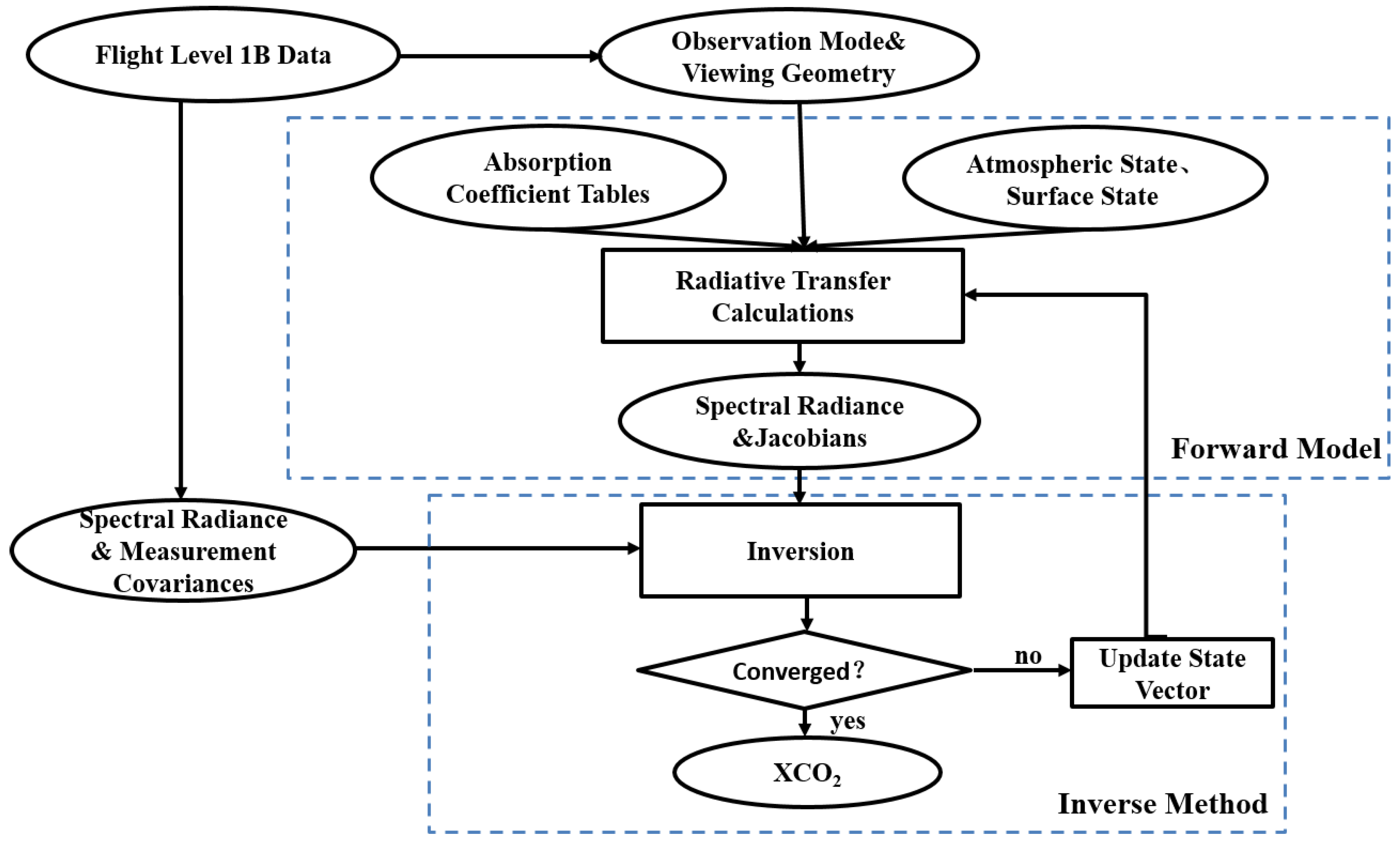
In this study, the retrieval algorithm is primarily used for simultaneously fitting the O2 A-band at 760 nm and the CO2 band at 1610 nm to get column abundances of CO2 and O2 based on the optimal estimation method [20]. The retrieval algorithm is an iterative retrieval method which calls the radiative transfer model with updated parameters after each iteration step. The primary components of the flight XCO2 retrieval processing workflow are summarized in Figure 5. Given that the atmospheric and surface states and the observing geometry for a sounding, the forward model generates radiance spectra and Jacobians (as will be described in more detail in Section 3.1.1 below). This model first generates two synthetic spectra that fully resolves the solar spectrum, the absorption and scattering cross sections for each atmospheric gas and the reflecting surface. The inverse method is based on Rodger’s optimal estimation approach. This method modifies the initial state vector to minimize differences between the observed and simulated spectra from each sounding. This inverse method is described in more detail in Section 3.1.2 below.

3.1.1. Forward Model

Synthetic spectra were generated using a radiative transfer algorithm. Losses can be caused by absorption and the scattering of the atmosphere. The sources (i.e., gains) mainly come from atmospheric emission and multiple scattering, and the general expression of the radiative transfer is given by the following equation [21]:
μ d I ( τ , μ ) d τ = I ( τ , μ ) J ( τ , μ )
where μ is the cosine of the zenith angle, I is the specific intensity, J is the source function (multiple scattering), and τ is the optical depth.
The radiative transfer model SCIATRAN was used to solve Equation (1). SCIATRAN is a comprehensive software package for the modeling of radiative transfer processes in the terrestrial atmosphere and ocean in the spectral range from the ultraviolet to the thermal infrared (i.e., 0.18–40 μm) including multiple scattering processes, polarization, thermal emission and ocean-atmosphere coupling. The software is capable of modeling spectral and angular distributions of the intensity or the Stokes vector of the transmitted, scattered, reflected, and emitted radiation assuming either a plane-parallel or a spherical atmosphere [22].
The inputs and outputs of the SCIATRAN model can be seen in the Table 4. The solar irradiance spectra were acquired from Dr. Kurucz (http://kurucz.harvard.edu). Gas absorption and scattering cross sections were obtained from the SCIATRAN software package which incorporates a climatological database obtained from a 2D chemical transport model. The atmospheric state (temperature, humidity and pressure profiles), surface state and aerosol optical properties were taken from ground synchronous observations and the European Centre for Medium-Range Weather Forecasts (ECMWF) reanalysis data. A set of instrument line shape functions were provided by the Changchun Institute of Optics, Fine Mechanics and Physics, Chinese Academy of Sciences. The outputs of the forward model were synthetic spectra and Jacobians.

3.1.2. Inverse Method

The inversion was used to obtain the unknown geophysical parameters (CO2 and O2 profiles) which minimize the differences between the observed and synthetic spectra from each sounding. The inverse method is based on Rodger’s optimization algorithm in which the spectrum is expressed symbolically as in Equation (2):
y = F ( x , b ) +
where x is the unknown state vector, b is a set of quantities required by the forward model but not retrieved, F is the forward model, and are the spectral errors due to the measurements and the forward model.
To find the state vector with the maximum a posteriori probability, we minimized the cost function (Equation (3)):
χ 2 = ( y F ( x , b ) ) T S 1 ( y F ( x , b ) ) + ( x x a ) T S a 1 ( x x a )
where S is the error covariance matrix corresponding to the measurement vector, x a is the a priori state vector which holds the prior knowledge about the state vector elements and S a is the corresponding a priori error covariance matrix which specifies the uncertainties of the a priori state vector elements as well as their cross-correlations.
The Levenberg-Marquardt method was used to obtain the solution in an iterative manner (Equation (4)):
x i + 1 = x i + S ˜ [ K i T S 1 ( y F ( x i b ) ) S a 1 ( x i x a ) ]
S ˜ = ( K i T S 1 K i + ( 1 + γ ) S a 1 ) 1
where K is the Jacobian or weighting function matrix consisting of the derivatives of the forward model with respect to the state vector elements K = ∂F(x,b)/∂x. In the case of convergence, x i + 1 is the most probable solution given the measurements and prior knowledge and it is then denoted as the maximum a posteriori solution x ˜ of the inverse problem. S ˜ is the corresponding covariance matrix consisting of the variances of the retrieval state vector elements and their correlations. The damping factor γ adjusts the step size of the iteration in a way which ensures that each step further minimizes the cost function.
The inverse method continued to provide iterative improvements of the solutions until both of convergence criteria listed below were achieved and we could obtain CO2 and O2 column abundances:
(1)
The fitted residuals with root mean square error (RMSE) differences between synthetic and observation spectra less than some pre-determined threshold: 0.25% for CO2 and 2% for O2 window [4,13].
(2)
The normalized successive difference of the state vector is less than some pre-determined threshold (1%) in the TANSO-FTS SWIR L2 algorithm (see [2] for details).
For CO2 we derived column-averaged dry air mole fractions by normalizing the CO2 columns with the simultaneously retrieved oxygen columns retrieved from the O2 A-band. Oxygen is an accurate proxy for the air column because its mole fraction is well known and has negligibly small variations. Then XCO2 was calculated using Equation (6) [4,23] as follows:
XC O 2 = C O 2 c o l o 2 c o l / o 2 m f
where C O 2 c o l is the retrieved absolute CO2 column (in molecules/cm2), o 2 c o l is the retrieved absolute O2 column (in molecules/cm2), and o 2 m f   ( 0.2095 ) is the assumed (column-averaged) mole fraction of O2 used to convert the O2 column into a corresponding dry air column.

3.2. Derivation of Approximate XCO2 Surface

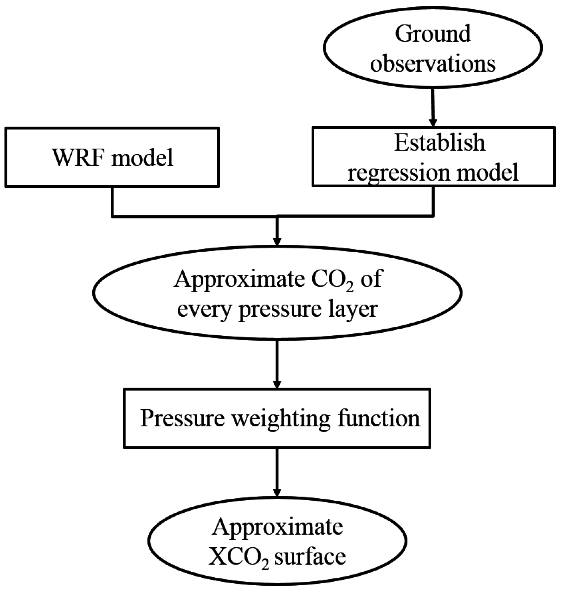
The approximate XCO2 surface in the flight test area was required to establish as the driving field of HASM (described in Section 3.3 below). The processing steps used to estimate the approximate XCO2 are summarized in Figure 6. Firstly, we used the least squares fit for the captive balloon’s CO2 profiles, the surface CO2 concentration in the surface layer and other synchronous ground observations to build a regression model [17,18]. Secondly, we combined the regression model with the Weather Research and Forecasting (WRF) model [24,25] to derive the approximate CO2 surface for every pressure layer in the whole flight test area. Finally, the pressure weighting function was used to merge every pressure layer’s CO2 surface to estimate the approximate XCO2 surface.

3.2.1. Initial Regression Model

We used an ordinary least squares multivariate linear fit method to build the regression models. The two groups of explanatory variables listed in Table 5 were used to build separate regression models for the CO2 concentrations in the surface layer [18] and the CO2 profile. We used the modeling spatial relationships/ordinary least square tools in ArcGIS to perform this work, and both models passed the F test at the 95% confidence level.
The CO2 concentration in every pressure layer at every grid point in the flight test area was then calculated as follows:
Y C O 2 = b + i = 1 n a i x i
where Y C O 2 is the CO2 concentration in every pressure layer, b is a constant, x represents the explanatory variables, a is the corresponding coefficient for each of the explanatory variables, and n is the number of explanatory variables.

3.2.2. WRF Model

WRF is a next-generation mesoscale numerical weather prediction system designed for both atmospheric research and operational forecasting needs. The model serves a wide range of meteorological applications across scales from tens of meters to thousands of kilometers. WRF can generate atmospheric simulations using real-world data or idealized conditions. WRF offers operational forecasting a flexible and computationally-efficient platform for operational forecasting using initial data from the US National Center for Environmental Prediction (NCEP).
The initial data used in this study were derived from reanalysis datasets of NCEP. We generated forecasts at 20:00 each day using an integrate interval of 30 h and 1 km by 1 km grid. Physical parameters were the YSU scheme, Monin Obukhov scheme, WSM 6-class graupel scheme, RRTM scheme (longwave), Goddard scheme (shortwave), Noah-MP land-surface model and Kain-Fritsch (new Eta) scheme respectively. We used WRF Version 3.5 to model the CO2 concentration at every point using the aforementioned explanatory variables in the flight test area on an hourly basis from 10:00 to 14:00 on the 11th, 14th, and 16th of September. We then used Equation (7) to calculate the approximate CO2 concentration of every pressure layer at each point in the flight test area.

3.2.3. Pressure Weighting Function

The pressure weighting function h relates the local CO2 concentration specified on the discrete pressure levels to the profile-weighted average [8], so XCO2 could be calculated as follows:
XCO 2 = i = 1 n h i u i
where u denotes the CO2 concentration and the subscripts refer to the layers, and:
h i = | ( p i + p i + 1 p i ln ( p i + 1 / p i ) ) + ( p i p i p i 1 ln ( p i / p i 1 ) ) | 1 p s u r f
where p denotes the pressure and the subscripts again refer to the layers, and p s u r f denotes the surface pressure. For the edge layers, if i = 1, only the left first term applies, that is h 1 = | ( p 1 + p 2 p 1 ln ( p 2 / p 1 ) ) | 1 p s u r f , while if i = n, only the left second term applies, that is h n = | ( p n + p n p n 1 ln ( p n / p n 1 ) ) | 1 p s u r f .
The approximate CO2 concentration for every pressure layer at each point in the flight test area was calculated using the methods described in Section 3.2.1 and Section 3.2.2. With the methods specified at this step, the approximate XCO2 was obtained by averaging the approximate CO2 concentration of every pressure layer, weighted by the pressure weighting function.

3.3. High Accuracy Surface Modeling

The high accuracy surface modeling [26] platform takes global approximate information (e.g., remote sensing images or model simulation results) as its driving field and local accurate information (e.g., ground observation and/or sampling data) as its optimum control constraints. A surface can be uniquely defined by the first and the second fundamental coefficients [27,28,29,30,31] in terms of the fundamental theorem of surfaces. The first fundamental coefficients are used to express the intrinsic geometric properties that do not depend on the shape of the surface, but only on measurements that we can carry out while on the surface itself. The second fundamental coefficients reflect the local warping of the surface, namely its deviation from a tangent plane at the point under consideration, which can be observed from outside the surface. The Earth’s surface system or a component surface of the Earth’s surface environment can be simulated with HASM when its spatial resolution is fine enough and is uniquely defined by both extrinsic and intrinsic invariants of the surface.
If a surface is a graph of a function z = f ( x , y ) , the first fundamental coefficients E, F and G can be formulated as
{ E = 1 + f x 2 G = 1 + f y 2 F = f x · f y
The second fundamental coefficients L, M and N can be formulated as
{ L = f x x 1 + f x 2 + f y 2 N = f y y 1 + f x 2 + f y 2 M = f x y 1 + f x 2 + f y 2
The first and the second fundamental coefficients should satisfy the following Gauss equation set:
{ f xx = Γ 11 1 · f x + Γ 11 2 · f y +L· ( E·G F 2 ) 1/2 f yy = Γ 22 1 · f x + Γ 22 2 · f y +N· ( E·G F 2 ) 1/2 f xy = Γ 12 1 · f x + Γ 12 2 · f y +M· ( E·G F 2 ) 1/2
where Γ 11 1 = 1 2 ( G · E x 2 F · F x + F · E y ) · ( E · G F 2 ) 1 , Γ 12 1 = 1 2 ( G · E y F · G x ) · ( E · G F 2 ) 1 , Γ 22 1 = 1 2 ( 2 G · F y G · G x F · G y ) · ( E · G F 2 ) 1 , Γ 11 2 = 1 2 ( 2 E · F x E · E y F · E x ) · ( E · G F 2 ) 1 , Γ 12 2 = 1 2 ( E · G x F · E y ) · ( E · G F 2 ) 1 , Γ 22 2 = 1 2 ( E · G y 2 F · F y + F · G x ) · ( E · G F 2 ) 1 are the Christoffel symbols of the second kind which depend only on the first fundamental coefficients and their derivatives.
Finite difference methods are used for solving the Gauss equation set (Equation (12)). It can be simplified as the following equation set [26]:
{ A · z ( n + 1 ) = d ( n ) B · z ( n + 1 ) = q ( n ) C · z ( n + 1 ) = p ( n )
If f i , j is the value of z = f ( x , y ) at the pth sampled point ( x i , y i ) in the computational domain, the simulation value should be equal or approximate to the sampling value of this lattice so that the constraint equation is added to the simplified equation set (Equation (13)). The matrix formulation of the HASM master equations can be expressed as follows [26]:
[ A T   B T   C T   λ · S T ] [ A B C λ · S ] z ( n + 1 ) = [ A T   B T   C T   λ · S T ] [ d ( n ) q ( n ) p ( n ) λ · k ]
where the parameter λ is the weight of the sampling points and determines the contribution of the sampling points to the simulated surface. λ could be a real number, which means all sampling points have the same weight, or a vector, which means every sampling point has its own weight. An area affected by a sampling point in a complex region is smaller than in a flat region. Therefore, a smaller value of λ is selected in a complex region and a bigger value of λ is selected in a flat region.
High accuracy surface modeling can simulate continuous attribute variations in three-dimensional space, and has been successfully used in simulating climate change [17,32,33], constructing DEMs [28,29], interpolating soil properties [34,35,36] and terrestrial land cover change [19]. For this study, HASM took the approximate XCO2 surface as its driving field and the flight retrieved XCO2 as its optimum control constraints as shown in Equation (15):
Xsim = HASM ( Xinitial , Xsam )
where Xsim is the final XCO2 surface which is calculated by HASM, Xinitial is the approximate XCO2 surface which is obtained by regression modeling, and Xsam is the retrieval XCO2. The main inputs of HASM are the retrieval XCO2 and the approximate XCO2 surface with the output being the high accuracy surface of XCO2.

4. Results

4.1. Retrieval XCO2

The XCO2 concentrations estimated with the full physics retrieval approach for about 400 points in the flight test area covering seven kinds of underlying surface—grassland, water, wetland, farmland, a thermal power plant, urban area and forest land—are shown in Figure 7.
The retrieval XCO2 concentrations ranged from 396.5 to 407.3 ppm with a mode of 396.5 to 397.3 ppm (Figure 7).

4.2. Approximate XCO2 Surface in the Flight Test Area

In order to model the high accuracy XCO2 surface, we first established the approximate XCO2 surface using an ordinary linear least squares regression model to represent the spatial relationships in the flight test area (Figure 8).
From Figure 3 and Figure 8, we can see that the mean XCO2 of this approximate surface is about 20 ppm lower than the retrieval XCO2 surface, but does show the estimated spatial relationships in the flight test area. It was used as the driving field of HASM, and the retrieval XCO2 was used as the optimum control constraints to model the XCO2 surface in the flight test area.

4.3. High Accuracy XCO2 Surface

The high accuracy surface model took the regression results as its driving field and the retrieval XCO2 values as its optimum control constraints to more accurately estimate the XCO2 surface in the whole flight test area (Figure 9).
The HASM XCO2 estimates in the flight test area ranged from 390.0 to 403.6 ppm. Combining the map in Figure 9 with the image showing the flight test area (Figure 3), we can see that XCO2 is highest in Songyuan City. Similarly, the XCO2 in another small city, Taonan, is higher as well. The XCO2 was lower in the Xianghai Reserve, which includes the Limin grassland, Hedao wetland and Xianghai Lake. The aforementioned results show how human activities can increase XCO2 and that the retrieval XCO2 calculated in this study was sensitive to the boundary layer which may be affected by human’s activities over relatively short distances.

4.4. Comparison with OCO-2’s XCO2 Estimates

The Orbiting Carbon Observatory 2 (OCO-2) which was launched on 2 July 2014, is NASA’s first dedicated Earth remote sensing satellite to study XCO2 from Space. OCO-2 is collecting space-based global measurements of XCO2 with the precision, resolution, and coverage needed to characterize sources and sinks on regional scales. OCO-2 is also able to quantify CO2 variability over seasonal cycles year after year. The OCO-2 instrument flies on a dedicated spacecraft and includes three high-resolution grating spectrometers which make coincident measurements of reflected sunlight in the near-infrared CO2 near 1610 and 2060 nm and in the molecular oxygen (O2) A-Band at 760 nm at a resolution of 1.29 (longitude) and 2.25 km (latitude). The XCO2 (Version OCO2_L2_Lite_FP.7r) at the 14 locations in the flight test area ranged from 396.7 to 398.3 ppm on 11–16 September 2014 (Figure 10).
The corresponding HASM XCO2 estimates were extracted from Figure 9 and used to calculate the differences from the OCO-2 XCO2 estimates (Table 6).
Twelve of the 14 HASM XCO2 estimates were higher than the corresponding OCO-2 estimates (column 6, Table 6) with the mean difference and standard deviation being 0.7 and 0.95 ppm, respectively. Given that the accuracy of the OCO-2 XCO2 estimates is about 1 ppm [37], the HASM modeling results based on the flight test of the TanSat instruments fell within the expected range.

5. Conclusions

This paper presents the validation of XCO2 based on a flight test of TanSat instruments using a combination of full physics and surface modelling. The results produced with this pair of methods were nevertheless sufficiently similar to justify using HASM to estimate the XCO2 surface. HASM took the approximate surface of XCO2 as its driving field and the flight’s retrieval XCO2 as its optimum control constraints to fill in the gaps across the whole flight test area. The results showed that the XCO2 in cities is higher than in other places suggesting that cities are places where human activities can lead to increased XCO2 concentrations. Compared with OCO-2’s XCO2, the mean difference is 0.7 ppm and the standard deviation is 0.95 ppm. Due to the good matching, the surface modelling of XCO2 based on the flight test of TanSat instruments fell within an expected and accepted range.
The flight test in this study was conducted in good weather conditions, so we assumed the sky was clear when the retrieval XCO2 estimates were acquired. In fact, the presence of clouds and aerosols could influence XCO2 and in the future, we plan to consider their impact. Moreover, the CO2 strong absorption band (i.e., 2060 nm) contains additional information on CO2 and H2O, but we did not use this band for the current flight test due to cost. Therefore, we will conduct XCO2 retrieval using three bands from other satellite data before TanSat is launched in the future.

Acknowledgments

This work was supported by the National Natural Science Foundation of China (Grant No. 91325204), the National High-tech R&D Program of the Ministry of Science and Technology of China (Grant No. 2013AA122003), and the National Key Technologies R&D Program of the Ministry of Science and Technology of China (Grant No. 2013BACO3B05). We are grateful to the OCO-2 teams for sharing the OCO-2 observations used in this paper.

Author Contributions

Li Li Zhang and Tian Xiang Yue conceived and designed the experiments; Li Li Zhang performed the experiments; Chao Lin and Yu Quan Zheng supplied the data; Yu Liu and Jian Hong Guo participated in the data processing; Na Zhao, Zheng Ping Du and Yi Fu Wang contributed analysis tools; Li Li Zhang wrote the paper; John Peter Wilson, Ding Yi Wang and Dong Dong Liu supervised the revision of the manuscript.

Conflicts of Interest

The authors declare no conflict of interest.

References

  1. Meehl, G.A.; Washington, W.M. El Nino-like climate change in a model with increased atmospheric CO2 concentrations. Nature 1996, 382, 56–60. [Google Scholar] [CrossRef]
  2. Yoshida, Y.; Ota1, Y.; Eguchi1, N.; Kikuchi, N.; Nobuta, K.; Tran, H.; Morino1, I.; Yokota, T. Retrieval algorithm for CO2 and CH4 column abundances from short-wavelength infrared spectral observations by the Greenhouse gases observing satellite. Atmos. Meas. Tech. 2011, 4, 717–734. [Google Scholar] [CrossRef]
  3. Oshchepkov, S.; Bril, A.; Maksyutov, S.; Yokota, T. Detection of optical path in spectroscopic space-based observations of greenhouse gases: Application to GOSAT data processing. J. Geophys. Res. 2011, 116, D14304. [Google Scholar] [CrossRef]
  4. Schneising, O.; Buchwitz, M.; Burrows, J.P.; Bovensmann, H.; Reuter, M.; Notholt, J.; Macatangay, R.; Warneke, T. Three years of greenhouse gas column-averaged dry air mole fractions retrieved from satellite—Part 1: Carbon dioxide. Atmos. Meas. Tech. 2008, 8, 3827–3853. [Google Scholar] [CrossRef]
  5. Guerlet, S.; Butz, A.; Schepers, D.; Basu, S.; Hasekamp, O.P.; Kuze, A.; Yokota, T.; Blavier, J.F.; Deutscher, N.M.; Griffith, D.W.T.; et al. Impact of aerosol and thin cirrus on retrieving and validating XCO2 from GOSAT shortwave infrared measurements. J. Geophys. Res. 2013, 118, 4887–4905. [Google Scholar]
  6. Boesch, H.; Toon, G.C.; Sen, B.; Washenfelder, R.A.; Wennberg, P.O.; Buchwitz, M.; Beek, R.D.; Burrows, J.P.; Crisp, D.; Christi, M.; et al. Space-Based near-infrared CO2 measurements: Testing the Orbiting Carbon Observatory retrieval algorithm and validation concept using SCIAMACHY observations over Park Falls, Wisconsin. J. Geophys. Res. 2006, 111, D23302. [Google Scholar]
  7. Boesch, H.; Baker, D.; Connor, B.; Crisp, D.; Miller, C. Characterization of CO2 Column Retrievals from Shortwave-Infrared Satellite Observations of the Orbiting Carbon Observatory-2 Mission. Remote Sens. 2011, 3, 270–304. [Google Scholar] [CrossRef]
  8. Connor, B.J.; Boesch, H.; Toon, G.; Sen, B.; Miller, C.; Crisp, D. Orbiting Carbon Observatory: Inverse method and prospective error analysis. J. Geophys. Res. Atmos. 2008, 113, D05305. [Google Scholar] [CrossRef]
  9. O’Dell, C.W.; Connor, B.; Boesch, H.; O’Brien, D.; Frankenberg, C.; Castano, R.; Christi, M.; Eldering, D.; Fisher, B.; Gunson, M.; et al. The ACOS CO2 retrieval algorithm—Part 1: Description andvalidation against synthetic observations. Atmos. Meas. Tech. 2012, 5, 99–121. [Google Scholar] [CrossRef]
  10. Bovensmann, H.; Buchwitz, M.; Burrows, J.P.; Reuter, M.; Krings, T.; Gerilowski, K.; Schneising, O.; Heymann, J.; Tretner, A.; Erzinger, J. A remote sensing technique for global monitoring of power plant CO2 emissions from space and related applications. Atmos. Meas. Tech. 2010, 3, 781–811. [Google Scholar] [CrossRef]
  11. Reuter, M.; Buchwitz, M.; Schneising, O.; Heymann, J.; Bovensmann, H.; Burrows, J.P. A method for improved SCIAMACHY CO2 retrieval in the presence of optically thin clouds. Atmos. Meas. Tech. 2009, 2, 2483–2538. [Google Scholar] [CrossRef]
  12. Schneising, O.; Bergamaschi, P.; Bovensmann, H.; Buchwitz, M.; Burrows, J.P.; Deutscher, N.M.; Griffith, D.W.T.; Heymann, J.; Macatangay, R.; Messerschmidt, J.; et al. Atmospheric greenhouse gases retrieved from SCIAMACHY: Comparison to ground-based FTS measurements and model results. Atmos. Meas. Tech. 2012, 12, 1527–1540. [Google Scholar] [CrossRef]
  13. Reuter, M.; Bovensmann, H.; Buchwitz, M.; Burrows, J.P.; Connor, B.J.; Deutscher, N.M.; Griffith, D.W.T.; Heymann, J.; Aleks, G.K.; Messerschmidt, J.; et al. Retrieval of atmospheric CO2 with enhanced accuracy and precision from SCIAMACHY: Validation with FTS measurements and comparison with model results. J. Geophys. Res. 2011, 116, D04301. [Google Scholar] [CrossRef]
  14. Heymann, J.; Reuter, M.; Hilker, M.; Buchwitz, M.; Schneising, O.; Bovensmann, H.; Burrows, J.P.; Kuze, A.; Suto, H.; Deutscher, N.M.; et al. Consistent satellite XCO2 retrievals from SCIAMACHY and GOSAT using the BESD algorithm. Atmos. Meas. Tech. 2015, 8, 2961–2980. [Google Scholar] [CrossRef]
  15. Cogan, J.; Boesch, H.; Parker, R.J.; Feng, L.; Palmer, P.I.; Blavier, J.F.L.; Deutscher, N.M.; Macatangay, R.; Notholt, J.; Roehl, C.; et al. Atmospheric carbon dioxide retrieved from the Greenhouse gases Observing SATellite (GOSAT): Comparison with ground-based TCCON observations and GEOS-Chem model calculations. J. Geophys. Res. 2012, 117, D21301. [Google Scholar] [CrossRef]
  16. Crisp, D.; Fisher, B.M.; O’Dell, C.; Frankenberg, C.; Basilio, R.; Boesch, H.; Brown, L.R.; Castano, R.; Connor, B.; Deutscher, N.; et al. The ACOS CO2 retrieval algorithm—Part II: Global XCO2 data characterization. Atmos. Meas. Tech. 2012, 5, 687–707. [Google Scholar] [CrossRef]
  17. Wang, C.L.; Zhao, N.; Yue, T.X.; Zhao, M.W.; Chen, C. Change trend of monthly precipitation in China with an improved surface modeling method. Environ. Earth Sci. 2015, 74, 6459–6469. [Google Scholar] [CrossRef]
  18. Liu, Y.; Guo, J.H.; Yue, T.X.; Zhao, N. Simulation and analysis of carbon dioxide concentration in surface layer. Geo-Inf. Sci. 2016, in press. [Google Scholar]
  19. Yue, T.X.; Fan, Z.M.; Chen, C.F.; Sun, X.F.; Li, B.L. Surface modeling of global terrestrial ecosystems under three climate change scenarios. Ecol. Model. 2011, 222, 2342–2361. [Google Scholar] [CrossRef]
  20. Rodgers, C.D. Inverse Methods for Atmospheric Sounding: Theory and Practice; World Scientific Publishing: Singapore, 2000. [Google Scholar]
  21. Li, W.B. Atmospheric Remote Sensing; Peking University Press: Beijing, China, 2014. [Google Scholar]
  22. Rozanov, V.V.; Rozanovn, A.V.; Kokhanovsky, A.A.; Burrows, J.P. Radiative transfer through terrestrial atmosphere and ocean: Software package SCIATRAN. J. Quant. Spectrosc. Radiat. Transf. 2014, 133, 13–71. [Google Scholar] [CrossRef]
  23. Wunch, D.; Toon, G.C.; Jean-François, L.B.; Rebecca, A.W.; Notholt, J.; Connor, B.J.; Griffith, D.W.T.; Sherlock, V.; Wennberg, P.O. The Total Carbon Column Observing Network. Philos. Trans. R. Soc. 2011, 369, 2087–2112. [Google Scholar] [CrossRef] [PubMed]
  24. Michalakes, J.; Dudhia, J.; Grill, D.; Klemp, J.; Skamarock, W. Design of a next-generation regional weather research and forecast model. In Towards Teracomputing: Proceedings of the Eighth ECMWF Workshop on the Use of Parallel Processors in Meteorology; World Scientific: River Edge, NJ, USA, 1998; pp. 117–124. [Google Scholar]
  25. Michalakes, J.; Chen, S.; Dudhia, J.; Hart, L.; Klemp, J.; Middlecoff, J.; Skamarock, W. Development of a Next Generation Regional Weather Research and Forecast Model. In Developments in Teracomputing: Proceedings of the Ninth ECMWF Workshop on the Use of High Performance Computing in Meteorology; World Scientific: Singapore, 2001; pp. 269–276. [Google Scholar]
  26. Yue, T.X. Surface Modelling: High Accuracy and High Speed Methods; CRC Press: Boca Raton, FL, USA, 2011. [Google Scholar]
  27. Yue, T.X.; Du, Z.P.; Song, D.J.; Gong, Y. A new method of surface modeling and its application to DEM construction. Geomorphology 2007, 91, 161–172. [Google Scholar] [CrossRef]
  28. Yue, T.X.; Chen, C.F.; Li, B.L. An adaptive method of high accuracy surface modeling and its application to simulating elevation surfaces. Trans. GIS 2010, 14, 615–630. [Google Scholar] [CrossRef]
  29. Yue, T.X.; Song, D.J.; Du, Z.P.; Wang, W. High-Accuracy surface modelling and its application to DEM generation. Int. J. Remote Sens. 2010, 31, 2205–2226. [Google Scholar] [CrossRef]
  30. Yue, T.X.; Wang, S.H. Adjustment computation of HASM: A high-accuracy and high-speed method. Int. J. Geogr. Inf. Sci. 2010, 24, 1725–1743. [Google Scholar] [CrossRef]
  31. Yue, T.X.; Zhang, L.L.; Zhao, N.; Zhao, M.W.; Chen, C.F.; Du, Z.P.; Song, D.J.; Fan, Z.M.; Shi, W.J.; Wang, S.H.; et al. A review of recent developments in HASM. Environ. Earth Sci. 2015, 74, 6541–6549. [Google Scholar] [CrossRef]
  32. Yue, T.X.; Zhao, N.; Yang, H.; Song, Y.J.; Du, Z.P.; Fan, Z.M.; Song, D.J. The multi-grid method of high accuracy surface modelling and its validation. Trans. GIS 2013, 17, 943–952. [Google Scholar] [CrossRef]
  33. Yue, T.X.; Zhao, N.; Ramsey, D.; Wang, C.L.; Fan, Z.M.; Chen, C.F.; Lu, Y.M.; Li, B.L. Climate change trend in China, with improved accuracy. Clim. Chang. 2013, 120, 137–151. [Google Scholar] [CrossRef]
  34. Shi, W.J.; Liu, J.Y.; Song, Y.J.; Du, Z.P.; Chen, C.F.; Yue, T.X. Surface modelling of soil pH. Geoderma 2009, 150, 113–119. [Google Scholar] [CrossRef]
  35. Shi, W.J.; Liu, J.Y.; Du, Z.P.; Stein, A.; Yue, T.X. Surface modelling of soil properties based on land use information. Geoderma 2011, 162, 347–357. [Google Scholar] [CrossRef]
  36. Shi, W.J.; Yue, T.X.; Du, Z.P.; Wang, Z.; Li, X.W. Surface modeling of soil antibiotics. Sci. Total Environ. 2016, 543, 609–619. [Google Scholar] [CrossRef] [PubMed]
  37. Wunch, D.; Wennberg, P.O.; Osterman, G.; Fisher, B.; Naylor, B.; Roehl, C.M.; O’Dell, C.; Mandrake, L.; Viatte, C.; Griffith, D.W.T.; et al. Comparisons of the Orbiting Carbon Observatory-2 (OCO-2) XCO2 measurements with TCCON. Atmos. Meas. Tech. Discuss. 2016. [Google Scholar] [CrossRef]
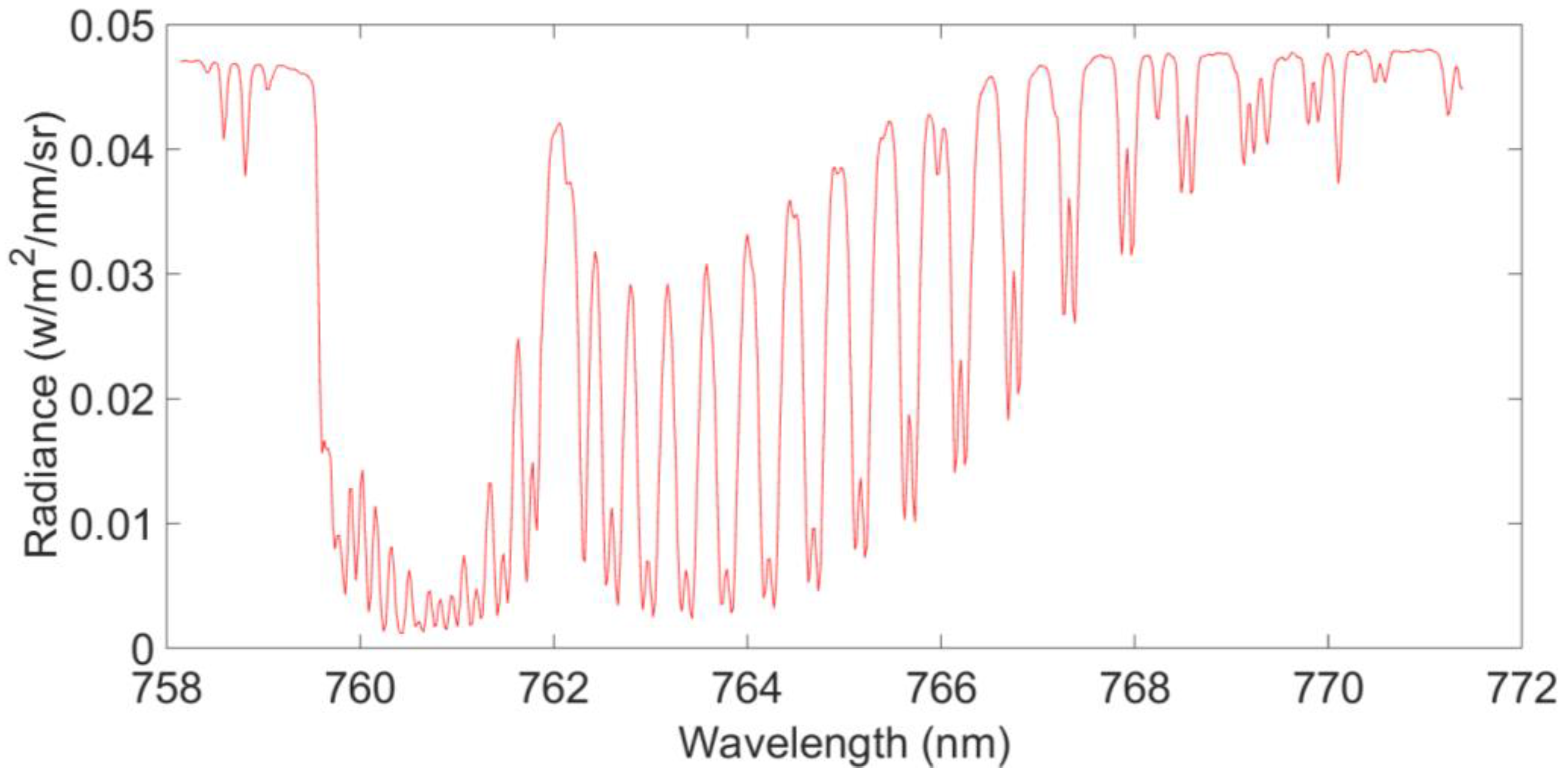
Figure 1. Band 1’s flight test observational L1B data: spectral radiance in 760 nm.
Sensors 16 01818 g001
Figure 2. Band 2’s flight test observational L1B data: spectral radiance in 1610 nm.
Sensors 16 01818 g002
Figure 3. The flight test area showing: (a) the overall flight test area; (b) Xianghai Reserve; and (c) the Changan Lake area.
Sensors 16 01818 g003
Figure 4. The overall workflow.
Sensors 16 01818 g004
Figure 5. Major components and tasks included in the retrieval algorithm workflow.
Sensors 16 01818 g005
Figure 6. Workflow used to estimate approximate XCO2 surface.
Sensors 16 01818 g006
Figure 7. XCO2 concentrations estimated in the flight test area using full physics retrieval approach.
Sensors 16 01818 g007
Figure 8. Approximate XCO2 surface in the flight test area.
Sensors 16 01818 g008
Figure 9. The XCO2 concentrations in the flight test area estimated with HASM.
Sensors 16 01818 g009
Figure 10. The XCO2 estimates from OCO-2 in the flight test area.
Sensors 16 01818 g010
Table 1. Flight parameters.
TypeParameters
Flight height5 km ± 30 m
Flight speed220 ± 6.6 km/h
Flight time10:30–13:30
Solar zenith angle40°–55°
Flight geometric requirementsFlight drift angle is <5°; range of three-axis attitude angle is <2°; route is straight and course deviation is <60 m.
Meteorological conditionsGood weather with visibility >10 km.
Table 2. NIR spectral bands used for the flight retrieval.
Band 1Band 2
Wavelength range (nm)758–7721592–1625
Spectral resolution (nm)0.044 0.13
Table 3. List of ground observations and methods used to gather them.
ObservationsObservation Methods Used
Temperature profileSonde measurement
Humidity profileSonde measurement
Pressure profileSonde measurement
Wind profileSonde measurement
CO2 profile Captive balloon
CO2 concentration in surface layerGreenhouse gases online laser analyzer UGGA
Surface reflectance Analytical Spectral Devices (ASD) spectrometer
Aerosol optical depthSun photometer CE318
Table 4. SCIATRAN model inputs and outputs.
InputsOutputs
Solar irradiance spectraRadiance spectrum
Gas absorption and scattering cross sectionsJacobians (partial derivatives of the radiance spectrum with respect to each of the state vector elements)
Atmospheric state-
Surface state-
Instrument line shape function-
Aerosol optical properties-
Table 5. Explanatory variables used to model CO2 in different layers.
Dependent VariablesExplanatory Variables
CO2 concentration in surface layerSurface pressure, atmospheric humidity, atmospheric temperature, soil humidity, soil temperature, upward and downward shortwave radiation, altitude, longitude and latitude
CO2 profile (not including surface layer)Temperature, pressure and humidity profiles, wind speed and direction, latitude and longitude
Table 6. The XCO2 difference between HASM and OCO-2 estimates in the flight test area.
NumberLongitude (°)Latitude (°)Flight Test (ppm)OCO-2 (ppm)Difference (ppm)
1124.3545.34396.67398.34−1.67
2124.4045.06399.13397.541.59
3124.4245.07398.85397.071.78
4124.4745.01398.05397.350.70
5124.4845.00398.36397.490.87
6124.4844.99398.05397.840.21
7124.4945.02398.75397.421.33
8124.4944.98397.82397.250.57
9124.5045.00399.01397.231.78
10124.5044.98398.73397.631.10
11124.5044.96397.99396.731.26
12124.5044.93397.24397.040.20
13124.5144.96397.92397.290.63
14124.5244.94397.35397.87−0.52