A Novel Robust Trilateration Method Applied to Ultra-Wide Bandwidth Location Systems


Key Laboratory of Intelligent Control and Decision of Complex Systems, School of Automation, Beijing Institute of Technology, Beijing 100081, China
*
Authors to whom correspondence should be addressed.
Sensors 2017, 17(4), 795; https://doi.org/10.3390/s17040795
Submission received: 14 February 2017
/
Revised: 25 March 2017
/
Accepted: 31 March 2017
/
Published: 7 April 2017
(This article belongs to the Special Issue Sensors and Sensing in Indoor Localization, Tracking, Navigation and Activity Monitoring)
Abstract
:Due to the non-line-of-sight (NLOS) and multipath fading channel (MPF) of the wireless networks, the non-existence of the intersection point often occurs in the range-based localization methods, e.g., the centroid-based trilateration method. To alleviate the problem, a confidence-based intersection method which expands the range of the circle within a certain confidence interval is proposed. In the method, the confidence interval is estimated based on the Cramér–Rao lower bound of the time of flight (TOF) measurement. Furthermore, an intersection determination method is proposed to select the intersection point with higher confidence level. The simulation and experimental results show the superiority of the proposed method in localization accuracy and robustness to noise compared to the conventional trilateration method, e.g., the centroid-based and least squares based trilateration methods.
1. Introduction
Nowadays, with the development of the wireless communication and electrical technology, low-cost, small-size and multi-functional sensor nodes have been largely used in the miliary, healthcare and domestic area [1]. As the basis of the Internet of Things (IOT), the sensor/agent localization is a fundamental task in many applications, e.g., mobile wireless device information sharing, path searching across the in-vehicle networks (IVN), indoor localization and surveillance systems [2,3,4].
Sensor localization has attracted tremendous interest of researchers concentrating on the following three topics. The first topic is how to increase the accuracy of the localization algorithm based on the communication of sensors. One effective approach is to recompute the distance at each sensor by exchanging the computed distance values with the neighbors, as is formulated as a neighbor-based collaborative localization method in [2,5]. The second topic is how to combine the benefits of the several existing localization algorithms. For example, the bounding box method proposed in [6] can obtain higher accuracy with low computation complexity and high coverage speed but is susceptible to the outliers or noise. Therefore, by combining the bounding box method with an outliers-robust trilateration method, both the accuracy and the robustness can be satisfied. The third topic is how to improve or extend the existing algorithms into various environments. One effective approach is to use multiple measurement methods—e.g., [7] proposed an indoor localization method which uses receiver signal strength indicator (RSSI) range and Zigbee communication protocols. In conclusion, the development of the localization algorithms in WSNs (wireless sensor networks) focus on the the algorithm design in complex environments and how to reduce the localization errors.
The ultra-wideband (UWB) technique is a commonly-used technique in the field of wireless sensor network localization. The signal is decomposed in time scale instead of the frequency or band scale, preventing the insurmountable technical barriers of the infinite spectral segment. UWB radios have relative bandwidth larger than or absolute bandwidth of more than 5000 MHz. The operating frequency of UWB is 3.1–10.6 GHz and can produce the narrow pulse directly to activate the antenna. It has very good characteristics such as low power, strong anti-interface capacity, insensitivity to channel fading, good elusiveness, high penetrability and high positioning accuracy [8]. Therefore, the UWB technique is well suited for high accuracy ranging and localization [9].
According to whether the range is measured or not, the localization mechanisms are divided into range-based methods and range-free methods. Range-free schemes, e.g., centroid [10], distance vector-hop (DV)-Hop [11], and approximate point-in-triangulation (APIT) [12], compute the location by exchanging information based on the connectivity of the networks. This scheme is easily implemented; however, it cannot obtain high localization accuracy. Range-based schemes, e.g., the trilateration, triangulation and maximum likelihood (ML) estimation, estimate the location by measuring the point-to-point distance or the angle and have better accuracy [13].
The ranging techniques for range-based methods include time of arrival (TOA), time difference of arrival (TDOA), time of flight (TOF) and arrival of angle (AOA) [14,15]. Among all the techniques, the TOF technique is commonly used in practice for its advantages, e.g., no need for accurate time synchronization, easy implementation and low consumed resources. It computes the range by calculating the time difference between the sender and receiver. For example, in [16], four ultrasonic TOF measurements and navigation position are used to compute the vehicle position based on the extended Kalman filter (EKF). In [17], a new hardware system is established to achieve the attitude tracking and path location for indoor autonomous robots.
According to [13], through the introduction of graph theory, the initial range-based location problem was transformed into a graph problem, which was proven to be an non-deterministic polynomial (NP) complete problem. Therefore, it is necessary to use the numerical methods, e.g., the trilateration method. Trilateration is the process that estimates the location of the target by measuring the distances of itself from three anchor nodes whose positions are already known. The anchors are required to install omnidirectional antenna and compute the distances by measuring the RSSI or other values. Then, the position of the target is estimated based on solving the intersection point of the three circles with the ranges being the radius and the anchor’s position being the center. However, in practice, there are four reasons that will influence the accuracy of the trilateration method, as are discussed below.
- Uncertainty: Due to the non-line-of-sight (NLOS) and multipath fading channel (MPF) problem, the uncertainty often occurs in the distance measurement procedure, which leads to the phenomenon that there are two intersection points of the anchor circles, and even no points.
- Heterogeneity: In most cases, the method requires three or more anchor nodes for broader coverage. Therefore, the inconsistency of the computation results may occur.
To solve the four problems, Reference [23] proposed a combination of the trilateration with a new geometric method for mobile robot localization. It established a series of geometric formulas including the Carley–Menger determinant to reduce a variety of error inferences, e.g., the multipath error and round-off error. Reference [24] proposed a confidence-based trilateration method which computes the location by selecting the sensors with the confidence level from high to low. At the initial time, the confidence level of each sensor is set according to the conditions, e.g., signal to noise ratio (SNR), the communication range, etc. In the iteration step of the implementation of localization, the confidence level is altered to reduce the localization error. This method can reduce the uncertainty and ambiguity problem efficiently but will increase the computational complexity of WSNs. Reference [25] studied the relationship between network localization and rigidity properties of ground truth graph, and proposed an improved trilateration for wheeled robot localization problem. The diffusion method is used to identify whether the the global grid is localizable or not. This method inherits the simplicity and efficiency of trilateration, and improves the ambiguity by identifying more localizable nodes. Reference [26] proposed the random sample consensus(RANSAC)-based trilateration method to robustly estimate an initial pose graph, which models the locations of sensor platforms. However, it lacks the consideration of two intersection points and non-existence of the intersection points, thus it cannot solve the uncertainty problem.
However, for an indoor environment with obstructions, the above improved methods do not consider the errors, which gives rise to the non-existence of the intersection point, so the narrow usage becomes its shortcoming. For UWB, the errors are composed of systematic errors and random errors. The systematic error stems from the NLOS propagation problem [27,28,29,30], which often occurs in the practical applications of WSN localization with multipath channels. The NLOS is caused by the measurement error induced by the in-network sensor failure. The conventional approach to the NLOS problem is to regard the NLOS error as the additive white Gaussian noise (AWGN) and reduce the interface by the errors based on the variance detection of least squares method (LS). However, it may cause the curse of dimensionality problem when calculating the pseudu-inverse matrix of LS estimate. This paper proposed a novel robust trilateration method to alleviate the problem. In the method, the interface is also modeled as AWGN, and a proper confidence interval is established to solve the non-existence of intersection points. A new intersection determination method is also proposed to reduce the errors induced by uncertainty and ambiguity.
The remainder of this paper is organized as follows. In Section 2, the problem of outlier-robust trilateration is formulated and prior works are illustrated. An improved confidence-based trilateration method with intersection determination criterion is developed in Section 3. The simulation and experimental results show the efficiency of the proposed method in Section 4. Conclusions are demonstrated in Section 6.
2. Problem Formulation
Consider the traditional trilateration method with two following assumptions:
Assumption 1.
The transmission channel is modeled as an AGWN channel, so the residuals between the measurement of range and the real value satisfies the Gaussian distribution.
Assumption 2.
The ranging error induced by the coordination faults (e.g., the hardware and rounding calculation errors) is bounded, and the upper bound is limited to satisfy the Gaussian property of the distance.
Given the two assumptions, the traditional trilateration is given as follows.
Consider a sensor network consisting of N anchor nodes and a target deployed over a geographic region. The coordinates of the anchor nodes are known, denoted as . denotes the coordinate of the target node. The distance between each anchor i and the target can be calculated by the time of flight (TOF) estimate, denoted as . Then, the following equations are satisfied:
The intersection point can be derived by solving the simultaneous equations of two nodes i and j as
where the solutions to the binary quadratic simultaneous equations denoted as and are derived as
where
The sufficient condition of the solution is to satisfy the following intersection judgement formula:
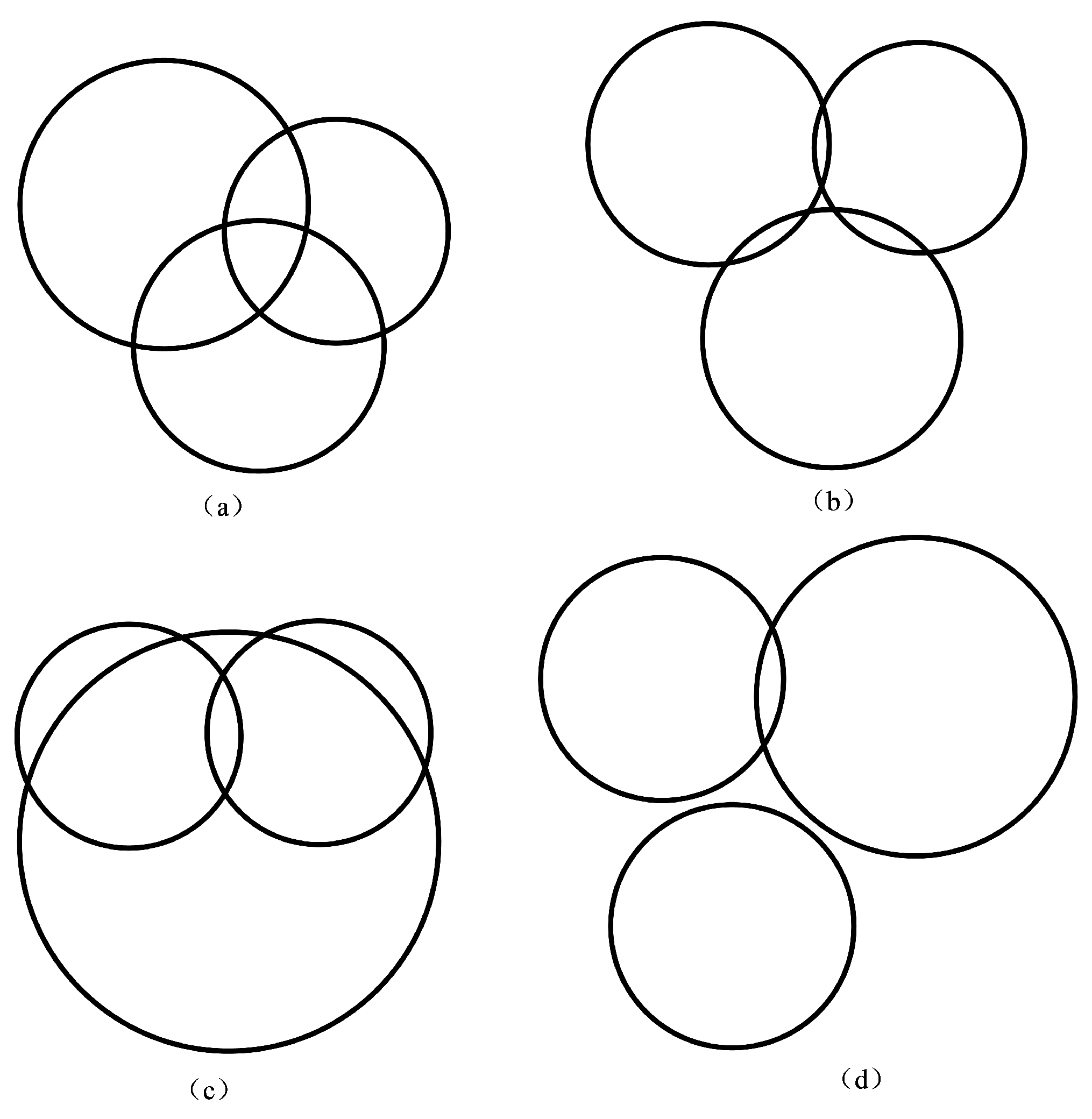
Ideally, all three of the circles intersect at only one point; however, in practice, the existence of the noises will lead to two intersection points, or even no intersection point, as shown in Figure 1.
As is shown from the figure, Figure 1a–c refer to the two intersections of anchor circles, where the intersection determination criterion is necessary to determine the “best” intersection. In addition, Figure 1d refers to no intersection points, where the distance compensation can be applied to alleviate the problem.
2.1. Intersection Determination
Traditional trilateration methods [23,24] adopt the following intersection determination criterion to determine the intersection point that is close to the center of the third circle:
where is the center of the third anchor circle k when selecting the “best” intersection point of anchor circle i and j. If the Equation (5) is satisfied, then select as the “best” intersection point, denoted as . Otherwise, select as .
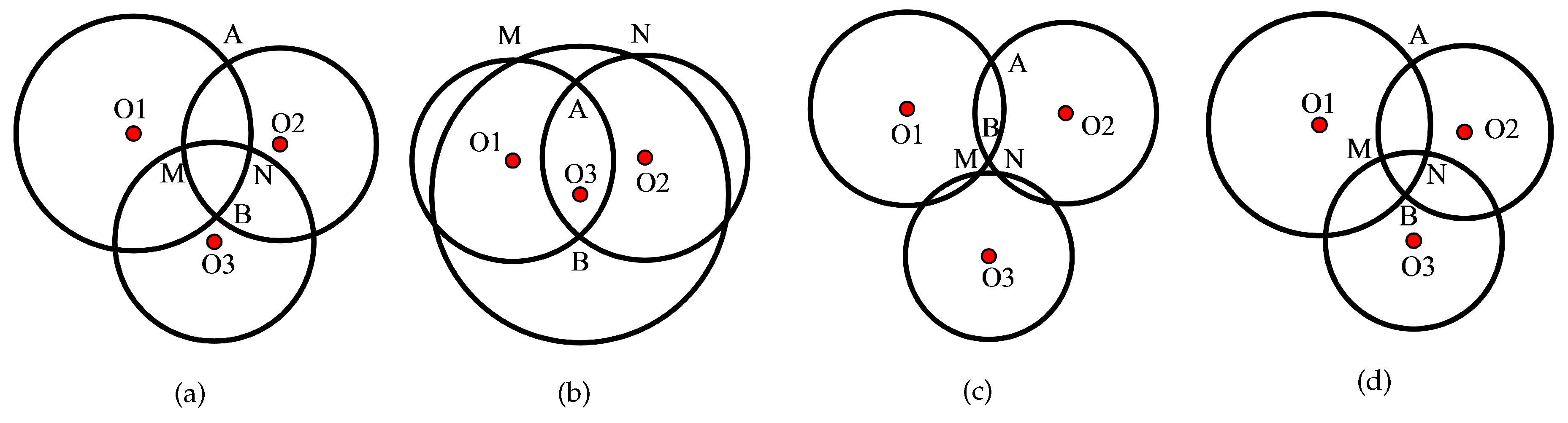
However, this method cannot be extended to all the possibilities of intersection, as shown in Figure 2.
As is indicated from the figure, the “best” intersection points based on Equation (5) are B, B, B and B for Figure 2a–d. However, according to hypotheses 1 and 2, the ranging measurement follows the Gaussian distribution with the mean as the actual range and low variance. Thus, the actual position of the target is more likely to be close to the anchor circle. Specifically, for Figure 2a,b, the real position of the target falls into the triangle region with a higher possibility than the triangle region , and so the real position is A and A with a high possibility for Figure 2a,b. Therefore, the traditional intersection determination method is sensitive to the noises. To increase the robustness, an improved intersection determination method is proposed in this paper, as shown in Section 3.
2.2. Distance Compensation
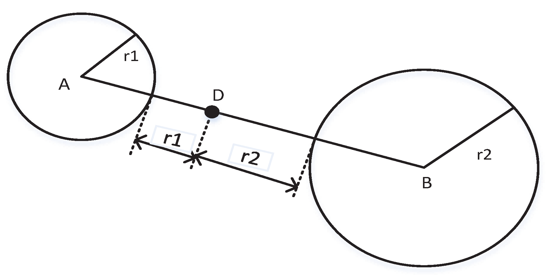
The distance compensation methods are often applied to solve the non existence problem of the intersection points. It compensates for the distance by extending the radius of the anchor circle when detecting no intersection points of the anchor circles. Reference [31] proposed a weighted trilateration method to obtain the point of the intersection based on the AWGN channel. It calculates the expanded distance as the weighted distance along the line crossing the centers whose weight is computed as the ratio of the radii of circles, as is shown in Figure 3.
However, the method is only suitable for signal-strength based positioning technique, e.g., RSSI, and not suitable for the time-based approach, e.g., TOA and TOF. Furthermore, the presence of large ranging errors induced by NLOS or MPF can also complicate the AWGN channel. These errors make the tails of the distribution of TOF estimates heavier than Gaussian, resulting in the impracticality of the above method in many applications. Therefore, new localization systems should be designed to be robust to these large errors. This paper proposed a novel confidence-based trilateration method based on the Cramér–Rao lower bound (CRLB) of TOF estimate with NLOS propagation in the MPF channel, as shown in Section 3.
3. Improved Confidence-Based Trilateration Method
We first give the CRLB of the time of flight (TOF) estimate with NLOS propagation in the MPF channel based on the discussion in [9].
3.1. CRLB of TOF Estimation with NLOS Propagation in the MPF Channel
As a time-based positioning technique, the TOF relies on measurements of travel times of signals between nodes. Unlike other time-based techniques, e.g., TOA and TDOA, TOF measures twice the travel times of signals between nodes by letting the receiver send back the signals immediately after it receives them. Therefore, it does not require time synchronization of the nodes. Since the communication channel is modeled as AWGN according to the Assumption 1, it can be shown that the distance estimate satisfies the following inequality:
where c is the speed of light, is the signal-to-noise ratio, and is the effective signal bandwidth defined by
with being the Fourier transform of the transmitted signal. As is indicated from the above equations, the CRLB of TOF estimate is only determined by the emission power and the bandwidth of the transmitted signal.
In a UWB positioning system, when the direct LOS between two nodes is blocked, only reflections of the UWB pulse from scatters reach the receiving node. Therefore, the delay of the first arriving pulse does not represent the true TOF. Since the pulse travels an extra distance, a position bias called the NLOS error is present in the measured time delay. Suppose that the probability density function (pdf) of the NLOS delays l, is known a priori. According to the CRLB and the Fisher information matrix (FIM), the CRLB of the extra distance induced by the NLOS delay is
A receiver signal with the multipath components is expressed as
where is the amplitude. is the delay and can be computed as
The noises are independent white Gaussian processes with spectral density . Then, the pdf of the received signal that is conditioned on is
The CRLB of the receiver signal with multipath channel is calculated in [32] as:
where
where
is the autocorrelation function of the signal .
In conclusion, the CRLB of the TOF estimate with an NLOS environment in a MPF channel is calculated as
3.2. New Intersection Determination Principle
As is discussed in the Section 2.1, selecting the intersection points that are close to the center of the third anchor circle is not available. Aiming at the situation, we proposed a new intersection determination principle, as shown below.
Measurement Principle.
For three anchor circles with the centers and radii denoted as and , given the intersection points and of the anchor circle i and j, the optimal intersection point to calculate the position is selected as
If the inequality condition in the Equation (16) holds, then select as . Otherwise, select as .
Proof of Measurement Principle.
According to the two Assumptions 1–2 and the discussion of the CRLB of the TOF estimate with an NLOS environment in the MPF channel above, the ranging measurements of the sensors follows the Gaussian distribution with the mean as the true range and variance , i.e., . Therefore, the measured range satisfies the following equation
3.3. Confidence-Based Distance Compensation
It is known that the range d under an NLOS environment in the MPF channel follows the Student-t distribution with CRLB computed as the form in Equation (15). Then, the measurement of the distance locates in the confidence interval with a certain confidence level . is denoted as the half of the confidence interval with confidence level set to , and is calculated as follows:
As is discussed in Section 3, expanding the range measurement of one anchor node is one effective approach. For the non-existence of intersection of the ith anchor node and jth anchor node, the radius of the anchor circle is expanded by the new distance .
3.4. Positioning Method
Then, the procedure of the proposed trilateration method is developed as follows.
- For qth selection, select three anchor nodes from N nodes which positions are known, denoted as . Then, the positions satisfy the Equation (1).
- Simultaneous the two equations of the ith anchor and jth anchor. Applying the intersection judgement formula in (4), if the solutions to the equations exist, then go to step 4; otherwise, go to step 3.
- The range d is compensated by the new distance , where is calculated in the Equation (18). Go to step 2.
- Another two optimal intersection points and are determined following the steps 1–4. Based on the centroid-based trilateration method, the coordination of the target of qth combination can be computed as:
- By alternating the anchor nodes, then the coordination of the target can be computed following steps 1–5. Then, the estimate of the coordination of the target is computed as:
4. Results
4.1. Experiments
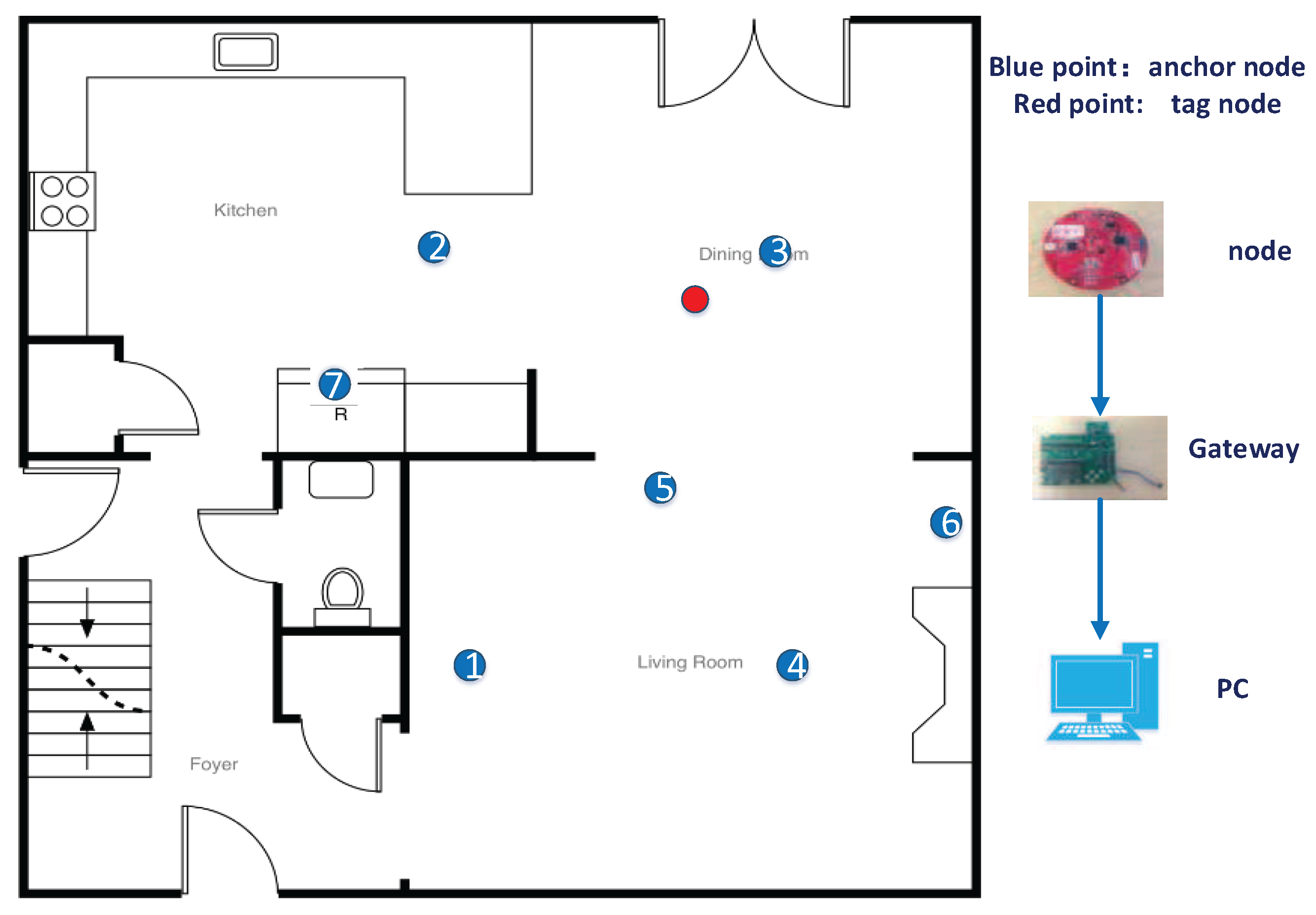
In the experiments, there are seven anchor nodes and one tag node (target) initially placed in a 25 m × 25 m square room, as shown in Figure 4. The hardware platforms of the anchor nodes, the tag node and gateway to the upper computer are shown on the right side of the figure. The DecaWave DWM1000 module, Dublin, Ireland is selected as the UWB ranging device that is installed on all the anchor nodes and the tag node. The TI SmartRF CC2538EM module, Dallas, TX, USA is selected as the communication device between all of the devices. Since the two-way ranging does not require accurate time synchronization, the time of flight method is applied to calculate the range by measuring elapsed time for a transmission between a tag and an anchor node based on the estimated propagation speed of an UWB signal through a medium.
The coordinates of the anchor nodes are set to , , , , , , , and , and the unit is meters. It should be noted that there is an obstruction between the seventh anchor node and the tag node. Therefore, the seventh anchor circle cannot intersect with other anchor circles due to the NLOS environment and the multipath fading channel.
4.2. Accuracy Performance
To show the efficiency of the proposed trilateration method in terms of the location accuracy, the root mean square error (RMSE) of the location is introduced as follows:
where is the estimate of the position of the ith selection scheme. N is the number of the selected sensors.
For comparison, we also ran the least squares method(LS)-based trilateration method on the same devices. The LS-based trilateration method is to compute the location estimate of the target as follows:
where
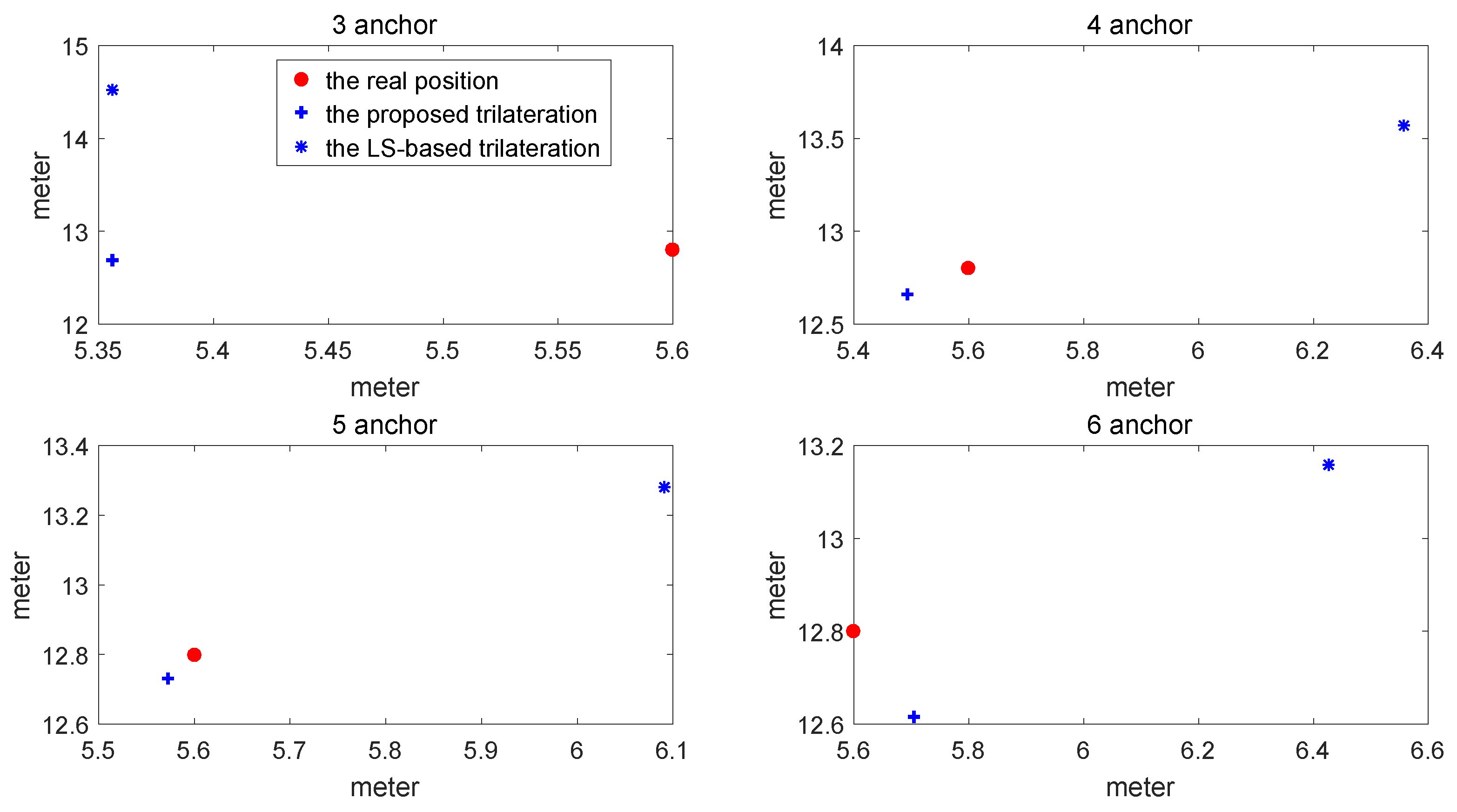
The comparison of location estimate between the proposed method and LS-based trilateration method is shown in Figure 5. The comparison of RMSE varying with the number of sensors between the proposed method and the conventional LS-based trilateration method is shown in Figure 6 and Table 1.
As is indicated from the above figures and the table, the RMSE of the proposed method is much lower than that of the LS-based trilateration method. Furthermore, even though the number of sensors is less than four, the RMSE of the proposed method is still less than 0.3. Therefore, the proposed trilateration method is efficient in terms of location accuracy.
4.3. Robustness Performance
To show the robustness of the proposed method, we reduce the range of each anchor node by 0.1 m and introduce the seventh anchor node. Thus, it may appear that two anchor circles may not intersect with each other.
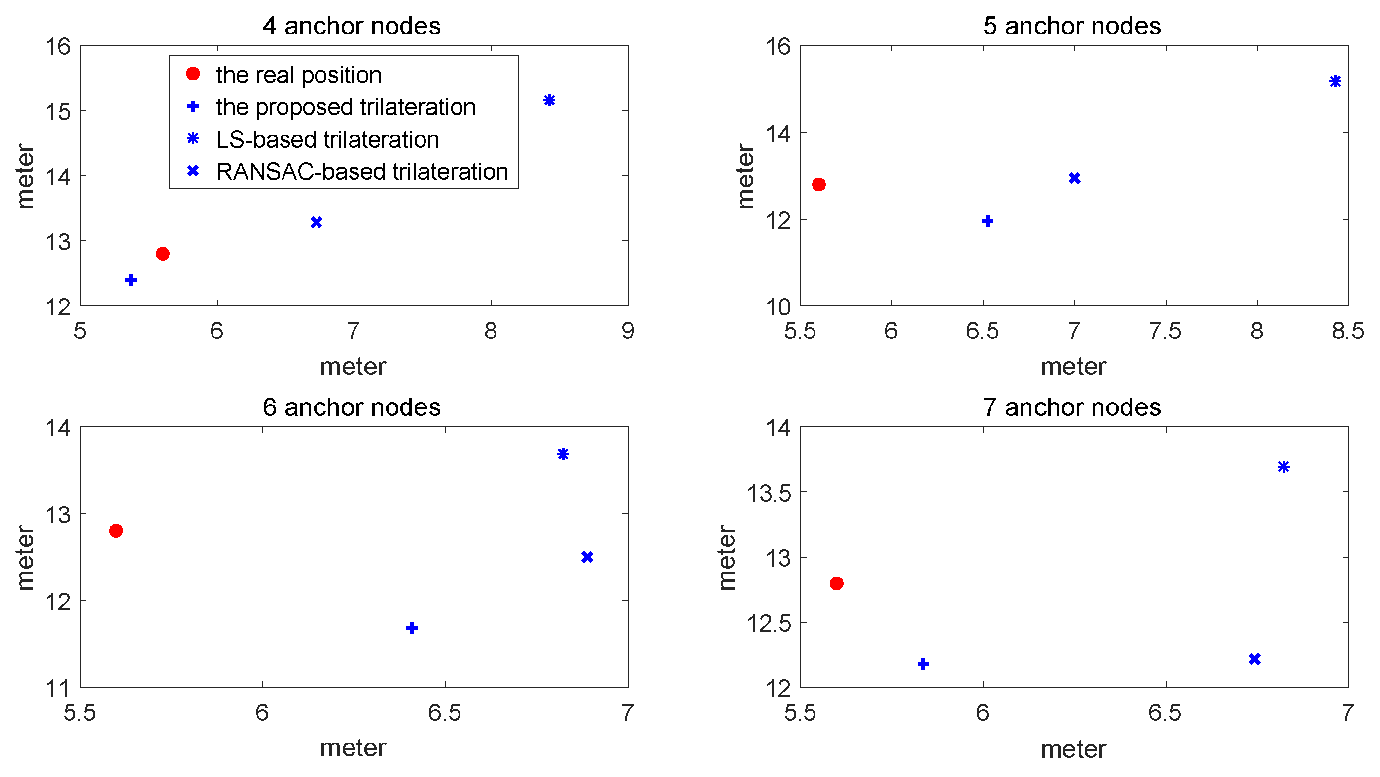
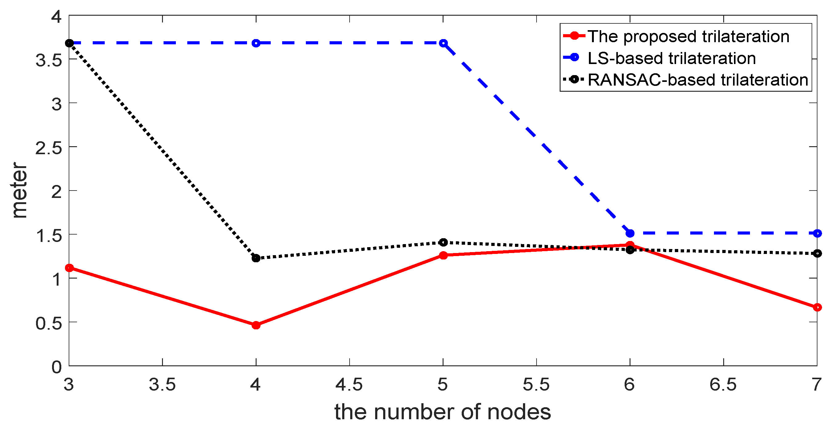
For comparisons, we also ran the LS-based trilateration method with the weighted method shown in [31] and the RANSAC-based robust trilateration method shown in [26]. In the RANSAC-based robust trilateration method, the general trilateration method is used to estimate the target and uses three consistency criterions to evaluate the correctness of the location estimate. The comparisons of the location estimate between these methods are shown in Figure 7. The comparisons of RMSE varying with the numbers of sensors are shown in Figure 8 and Table 2.
As is indicated from the above figures and the table, the RMSE of the proposed method is lower than that of the LS-based trilateration method and RANSAC-based trilateration method. Furthermore, when the seventh anchor node is added to compute the location, the RMSE of the proposed method is reduced whilst that of other methods are not, which shows that its distance is influenced by NLOS and the multipath fading channel is well compensated. Therefore, the proposed trilateration method is efficient in terms of robustness to outliers.
5. Discussion
In Figure 5 and Figure 6, the proposed trilateration has better estimated location and less RMSE than the LS-based trilateration varying with numbers of sensors. Thus, when the intersection points exist, the new intersection determination principle can select the intersection points which are close to the center of the third anchor circle and show good characteristics in solving the consistency and ambiguity problem. According to Figure 7 and Figure 8, the proposed positioning method based confidence-based distance compensation could make two circles that have no intersection points intersect again at a certain level of confidence. Therefore, the proposed method has better robustness performance than the RANSAC-based trilateration method and the LS-based trilateration method. In summary, as is indicated from the figures and the tables, the proposed method has better performance in accuracy and robustness than the LS-based method and the RANSAC-based trilateration method.
6. Conclusions
This paper proposed a new confidence-based robust trilateration method to solve the NLOS errors and MPF errors. A new intersection determination criterion for all the possibilities of intersection is provided to solve the consistency and ambiguity problem. For the non-existence of intersection points, a confidence-based distance compensation method is proposed to make two circles intersect again. The theoretical analysis is provided to show the efficiency of the method. The experimental results show the superiority of the proposed method compared to LS-based and RANSAC-based trilateration in terms of accuracy and robustness to outliers. Thus, the method can largely reduce the computation burden and improve the communication rate and the survivability of the sensors.
Acknowledgments
This work was supported in part by the National Natural Science Foundation of China under Grant 61321002 and 61120106010 and in part by Beijing NOVA Program xx2016B027.
Author Contributions
J.L. and J.C. conceived the research. J.L., X.Y. and F.D. designed the experiment and performed the data analysis. J.L. and X.Y. wrote the paper. J.C. and F.D. supervised the research and edited the paper. J.L. and X.Y. contributed equally to this work.
Conflicts of Interest
The authors declare no conflict of interest.
References
- Akyildiz, I.F.; Su, W.; Sankarasubramaniam, Y.; Cayirci, E. A survey on sensor networks. IEEE Commun. Mag. 2002, 40, 102–114. [Google Scholar] [CrossRef]
- Savarese, C.; Rabaey, J.M.; Beutel, J. Locationing in distributed ad-hoc wireless sensor networks. In Proceedings of the IEEE International Conference on Acoustics, Speech, and Signal, Salt Lake, UT, USA, 7–11 May 2001; Volume 4, pp. 2037–2040. [Google Scholar]
- Peneda, L.; Azenha, A.; Carvalho, A. Trilateration for indoors positioning within the framework of wireless communications. In Proceedings of the IEEE 35th Annual Conference of Industrial Electronics (IECON ’09), Porto, Portugal, 3–5 November 2009; pp. 2732–2737. [Google Scholar]
- Kulaib, A.R.; Shubair, R.M.; Al-Qutayri, M.A.; Ng, J.W.P. An overview of localization techniques for Wireless Sensor Networks. In Proceedings of the International Conference on Innovations in Information Technology, Abu Dhabi, United Arab Emirates, 25–27 April 2011; pp. 167–172. [Google Scholar]
- Shu, J.; Zhang, R.; Liu, L.; Wu, Z.; Zhou, Z. Cluster-based Three-dimensional Localization Algorithm for Large Scale Wireless Sensor Networks. J. Comput. 2009, 4, 1–3. [Google Scholar] [CrossRef]
- Savarese, C. Robust Positioning Algorithms for Distributed Ad-Hoc Wireless Sensor Networks. In Proceedings of the General Track of the Conference on Usenix Technical Conference, Berkeley, CA, USA, 10–15 June 2002; pp. 317–327. [Google Scholar]
- Lei, X.; Shi, W. Stepwise refinement localization algorithm for wireless sensor network. Chin. J. Sci. Instrum. 2008, 29, 314–319. [Google Scholar]
- Yang, L.; Giannakis, G.B. Ultra-wideband communications: an idea whose time has come. IEEE Signal Process. Mag. 2004, 21, 26–54. [Google Scholar] [CrossRef]
- Gezici, S.; Tian, Z.; Giannakis, G.B.; Kobayashi, H. Localization via ultra-wideband radios: A look at positioning aspects for future sensor networks. IEEE Signal Process. Mag. 2005, 22, 70–84. [Google Scholar] [CrossRef]
- Blumenthal, J.; Grossmann, R.; Golatowski, F.; Timmermann, D. Weighted Centroid Localization in Zigbee-based Sensor Networks. In Proceedings of the IEEE International Symposium on Intelligent Signal Processing, Alcala de Henares, Spain, 3–5 Octber 2007; pp. 1–6. [Google Scholar]
- Wang, J.; Chen, H. Study of Improved DV-Hop Localization Algorithm in Wireless Sensor Network. Int. J. Online Eng. 2013, 9, 66–70. [Google Scholar] [CrossRef]
- Stoleru, R.; He, T.; Mathiharan, S.S.; George, S.M.; Stankovic, J.A. Asymmetric Event-Driven Node Localization in Wireless Sensor Networks. IEEE Trans. Parallel Distrib. Syst. 2011, 23, 634–642. [Google Scholar] [CrossRef]
- Han, T.; Lu, X.; Lan, Q. Pattern recognition based Kalman filter for indoor localization using TDOA algorithm. Appl. Math. Model. 2010, 34, 2893–2900. [Google Scholar] [CrossRef]
- Gezici, S.; Sahinoglu, Z.; Molisch, A.F.; Kobayashi, H.; Poor, H.V. Two-Step Time of Arrival Estimation for Pulse-Based Ultra-Wideband Systems. EURASIP J. Adv. Signal Process. 2007, 2008, 1–11. [Google Scholar] [CrossRef]
- Gezici, S. A Survey on Wireless Position Estimation. Wirel. Pers. Commun. 2008, 44, 263–282. [Google Scholar] [CrossRef]
- Tsai, C. A localization system of a mobile robot by fusing dead-reckoning and ultrasonic measurements. IEEE Trans. Instrum. Meas. 1998, 47, 1399–1404. [Google Scholar] [CrossRef]
- Zhang, J.; Li, S.; Lu, G.; Zhou, Q. A new wireless sensor localization and pose tracking system for an Autonomous Mobile Robot. In Proceedings of the International Conference on Mechatronics and Automation, Xi’an, China, 4–7 August 2010; pp. 1971–1975. [Google Scholar]
- Wang, C.; Ma, H. Data Collection with Multiple Controlled Mobile Nodes in Wireless Sensor Networks. In Proceedings of the IEEE International Conference on Parallel and Distributed Systems, Tainan, Taiwan, 7–9 December 2011; pp. 489–496. [Google Scholar]
- Jiang, J.A.; Zheng, X.Y.; Chen, Y.F.; Wang, C.H. A Distributed RSS-Based Localization Using a Dynamic Circle Expanding Mechanism. IEEE Sens. J. 2013, 13, 3754–3766. [Google Scholar] [CrossRef]
- Savvides, A.; Han, C.C.; Strivastava, M.B. Dynamic fine-grained localization in Ad-Hoc networks of sensors. In Proceedings of the International Conference on Mobile Computing and Networking, Rome, Italy, 16–21 July 2001; pp. 166–179. [Google Scholar]
- Niculescu, D. Error Characteristics of Ad Hoc Positioning Systems. In Proceedings of the ACM Interational Symposium on Mobile Ad Hoc Network and Computing (MOBIHOC 2004), Tokyo, Japan, 24–26 May 2004; pp. 20–30. [Google Scholar]
- Whitehouse, K.; Karlof, C.; Woo, A.; Jiang, F.; Culler, D. The effects of ranging noise on multihop localization: An empirical study. In Proceedings of the International Symposium on Information Processing in Sensor Networks, Los Angeles, CA, USA, 24–27 April 2005; p. 10. [Google Scholar]
- Labat-Robert, J.; Robert, L. Revisiting trilateration for robot localization. IEEE Trans. Robot. 2005, 21, 93–101. [Google Scholar]
- Yang, Z.; Liu, Y. Quality of Trilateration: Confidence Based Iterative Localization. In Proceedings of the International Conference on Distributed Computing Systems, Piscataway, NJ, USA, May 2008; pp. 446–453. [Google Scholar]
- Yang, Z.; Liu, Y.; Li, X. Beyond Trilateration: On the Localizability of Wireless Ad Hoc Networks. IEEE/ACM Trans. Netw. 2010, 18, 1806–1814. [Google Scholar] [CrossRef]
- Dubbelman, G.; Duisterwinke, E.; Demi, L.; Talnishnikh, E. Robust sensor cloud localization from range measurements. In Proceedings of the 2014 IEEE/RSJ International Conference on Intelligent Robots and Systems, Chicago, IL, USA, 14–18 September 2014; pp. 3820–3827. [Google Scholar]
- Mao, G.; Fidan, B.; Anderson, B.D.O. Wireless sensor network localization techniques. Comput. Netw. 2007, 51, 2529–2553. [Google Scholar] [CrossRef]
- Xiong, L. A selective model to suppress NLOS signals in angle-of-arrival (AOA) location estimation. In Proceedings of the IEEE International Symposium on Personal, Indoor and Mobile Radio Communications, Boston, MA, USA, 8–11 September 1998; Volume 1, pp. 461–465. [Google Scholar]
- Chen, P. A Non-Line-Of-Sight Error Mitigation Algorithm In Location Estimation. In Proceedings of the Wireless Communications and Networking Conference (WCNC), New Orleans, LA, USA, 21–24 September 1999; Volume 1, pp. 316–320. [Google Scholar]
- Wylie, M.P.; Holtzman, J. The non-line of sight problem in mobile location estimation. In Proceedings of the IEEE International Conference on Universal Personal Communications, Piscataway, NJ, USA, 29 September–2 October 1996; Volume 2, pp. 827–831. [Google Scholar]
- Wei, B.; Yu, Z.; Huang, Z.; Chen, Z.; Wan, S. Weighting Trilateration Method in Local Positioning System. CN 102,540,140 B 3 July 2013. [Google Scholar]
- Qi, Y.; Kobayashi, H.; Suda, H. On Time-of-arrival Positioning in a Multipath Environment. IEEE Trans. Veh. Technol. 2006, 55, 1516–1526. [Google Scholar] [CrossRef]
Figure 1.
The diagrams of all possibilities of intersections of anchor circles influenced by noise. (a) diagram of two intersection points, one of which is outside and one of which is inside of the third circle; (b) diagram of two intersection points, both of which are outside of the third circle; (c) diagram of two intersection points, both of which are inside of the third circle; and (d) diagram of no intersection points.

Figure 2.
Diagrams of intersection determination schemes.

Figure 3.
Diagrams of weighted trilateration method.

Figure 4.
The diagram of the sensor deployment.

Figure 5.
Comparison of the estimated locations between the proposed method and the LS-based trilateration method.
Figure 5.
Comparison of the estimated locations between the proposed method and the LS-based trilateration method.

Figure 6.
Comparison of RMSE varying with numbers of sensors between the proposed method and the LS-based trilateration method.
Figure 6.
Comparison of RMSE varying with numbers of sensors between the proposed method and the LS-based trilateration method.
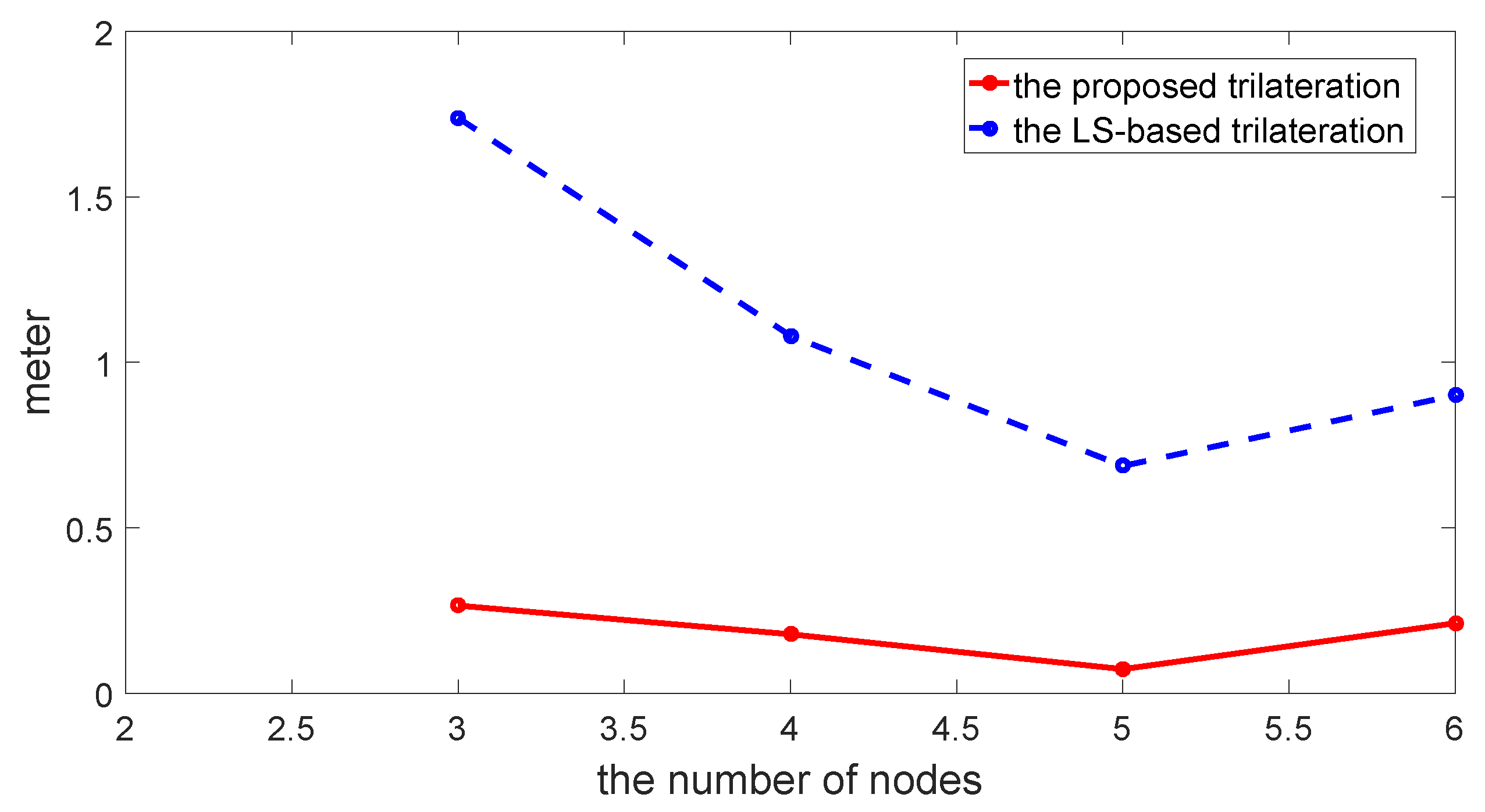
Figure 7.
Comparison of the estimated location among the proposed method, the LS-based trilateration method and the RANSAC-based method.
Figure 7.
Comparison of the estimated location among the proposed method, the LS-based trilateration method and the RANSAC-based method.

Figure 8.
Comparison of RMSE varying with numbers of sensors among the proposed method, the LS-based trilateration method and the RANSAC-based method.
Figure 8.
Comparison of RMSE varying with numbers of sensors among the proposed method, the LS-based trilateration method and the RANSAC-based method.


Table 1.
Comparison of RMSE between the proposed method and conventional LS-based method (m).
| Selection Schemes of the Anchor Nodes | Proposed Method | LS-Based Trilateration |
|---|---|---|
| ID: 1, 2, 3 | 0.2649 | 1.7385 |
| ID: 1, 2, 3, 4 | 0.1783 | 1.0801 |
| ID: 1, 2, 3, 4, 5 | 0.0729 | 0.6868 |
| ID: 1, 2, 3, 4, 5, 6 | 0.2117 | 0.9004 |
Table 2.
Comparison of RMSE among the proposed method, the LS-based trilateration method and the RANSAC-based method (m).
Table 2.
Comparison of RMSE among the proposed method, the LS-based trilateration method and the RANSAC-based method (m).
| Selection Schemes of the Anchor Nodes | Proposed Method | LS-Based Method | RANSAC-Based Method |
|---|---|---|---|
| ID:1,2,3 | 1.1200 | 3.6839 | 3.6839 |
| ID:1,2,3,4 | 0.4651 | 3.6839 | 1.2258 |
| ID:1,2,3,4,5 | 1.2605 | 3.6839 | 1.4073 |
| ID:1,2,3,4,5,6 | 1.3790 | 1.5140 | 1.3239 |
| ID:1,2,3,4,5,6,7 | 0.6654 | 1.5140 | 1.2814 |
© 2017 by the authors. Licensee MDPI, Basel, Switzerland. This article is an open access article distributed under the terms and conditions of the Creative Commons Attribution (CC BY) license (http://creativecommons.org/licenses/by/4.0/).
Share and Cite
MDPI and ACS Style
Li, J.; Yue, X.; Chen, J.; Deng, F. A Novel Robust Trilateration Method Applied to Ultra-Wide Bandwidth Location Systems. Sensors 2017, 17, 795. https://doi.org/10.3390/s17040795
AMA Style
Li J, Yue X, Chen J, Deng F. A Novel Robust Trilateration Method Applied to Ultra-Wide Bandwidth Location Systems. Sensors. 2017; 17(4):795. https://doi.org/10.3390/s17040795
Chicago/Turabian StyleLi, Jiahong, Xianghu Yue, Jie Chen, and Fang Deng. 2017. "A Novel Robust Trilateration Method Applied to Ultra-Wide Bandwidth Location Systems" Sensors 17, no. 4: 795. https://doi.org/10.3390/s17040795
Note that from the first issue of 2016, this journal uses article numbers instead of page numbers. See further details here.