Cupula-Inspired Hyaluronic Acid-Based Hydrogel Encapsulation to Form Biomimetic MEMS Flow Sensors


 , ,
, ,
Abstract
:1. Introduction
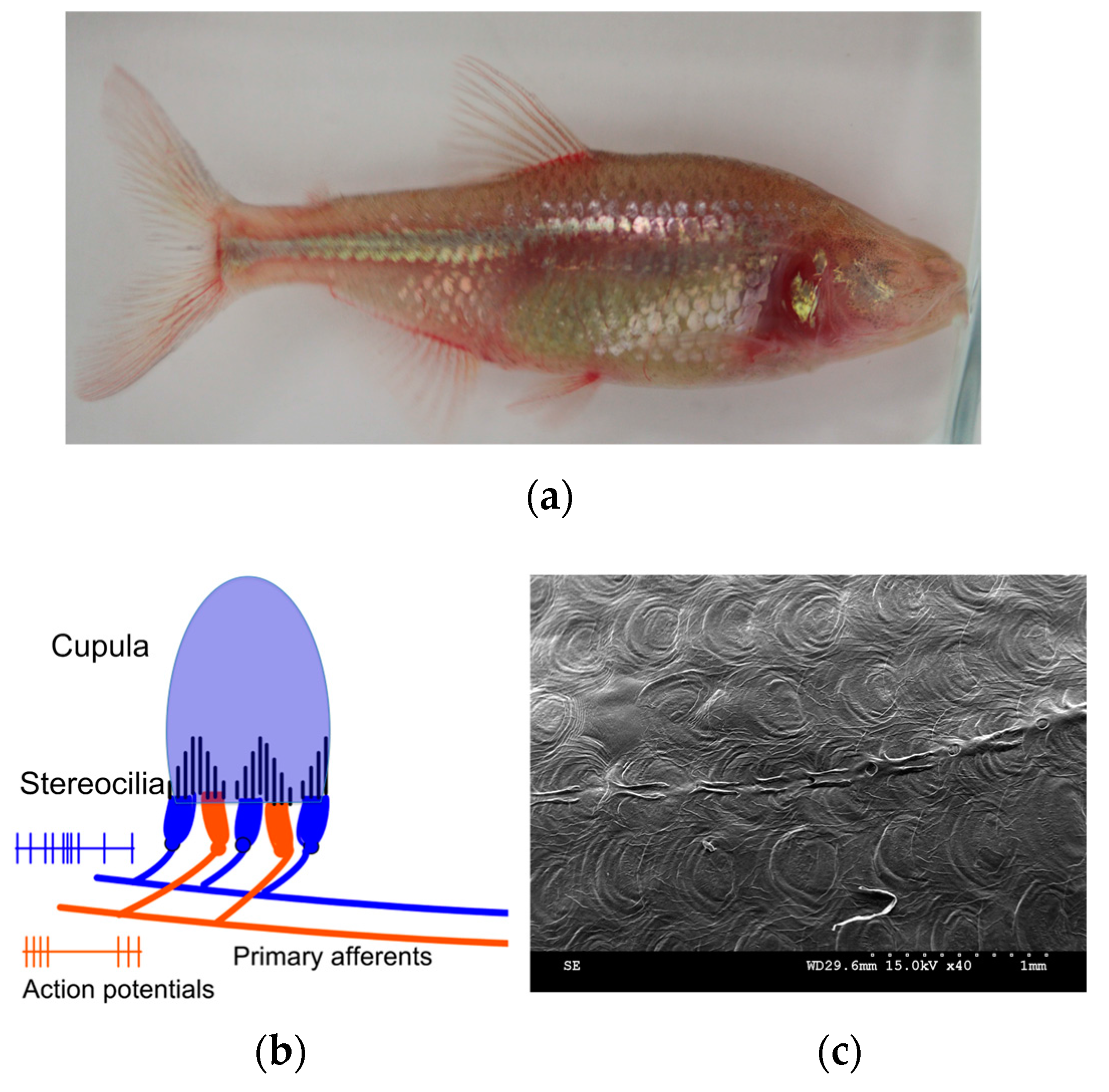
2. Bioinspiration
3. MEMS Artificial Neuromast
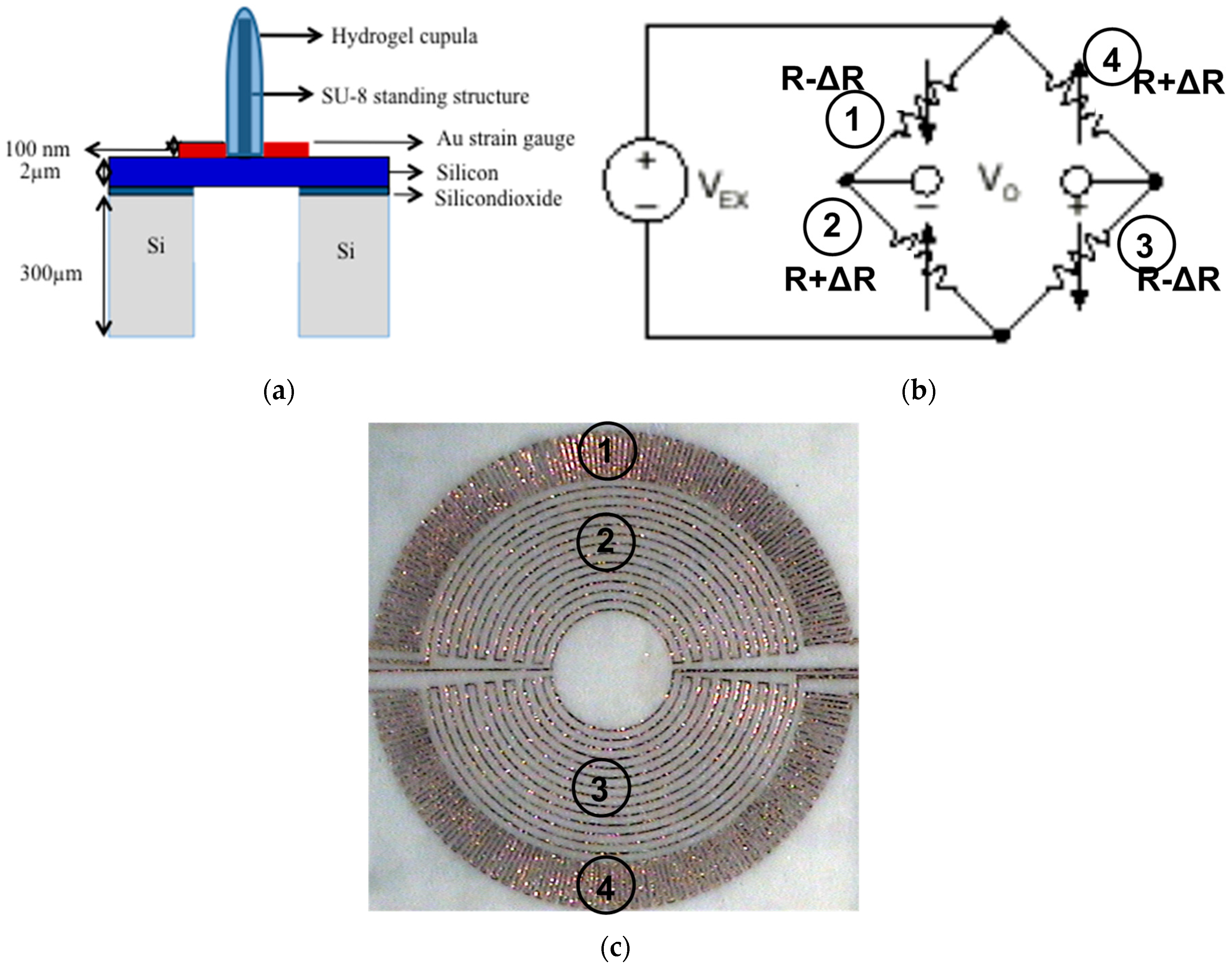
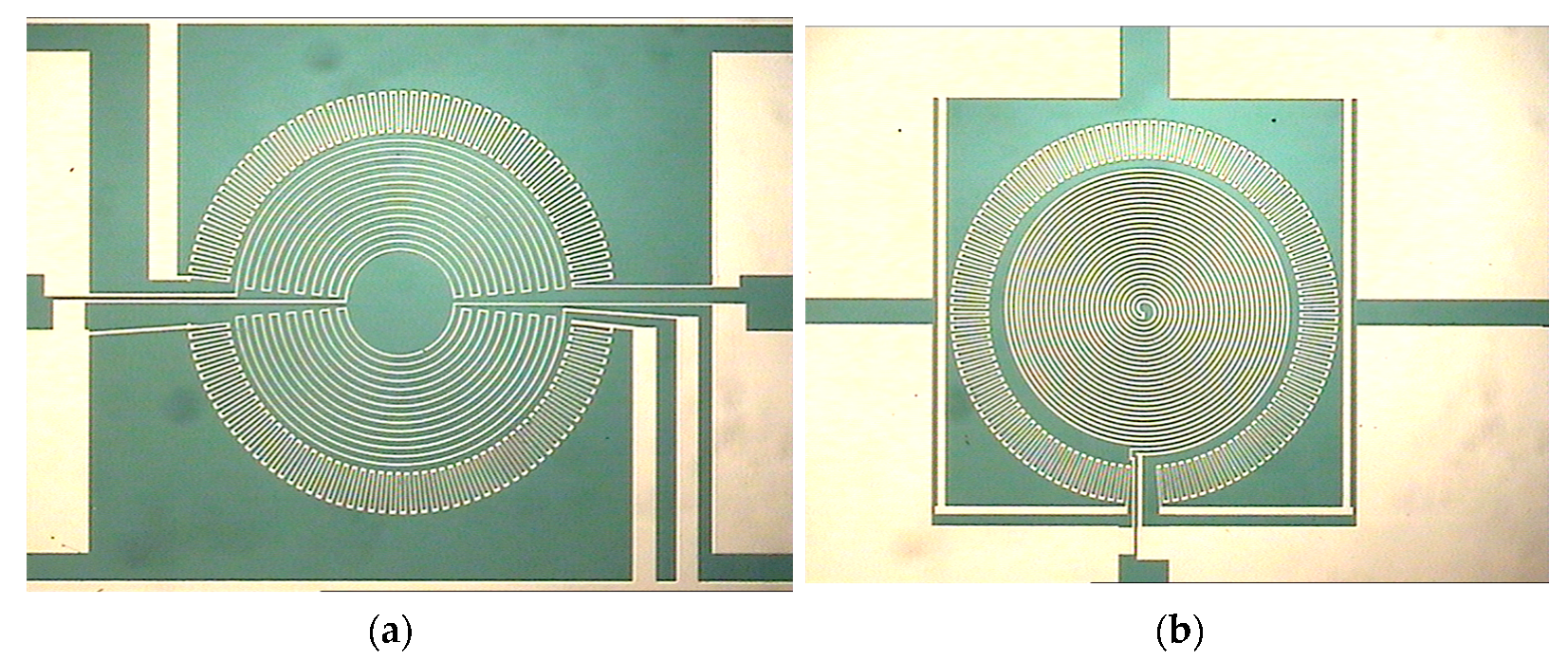
3.1. Sensor Structure and Sensing Principle
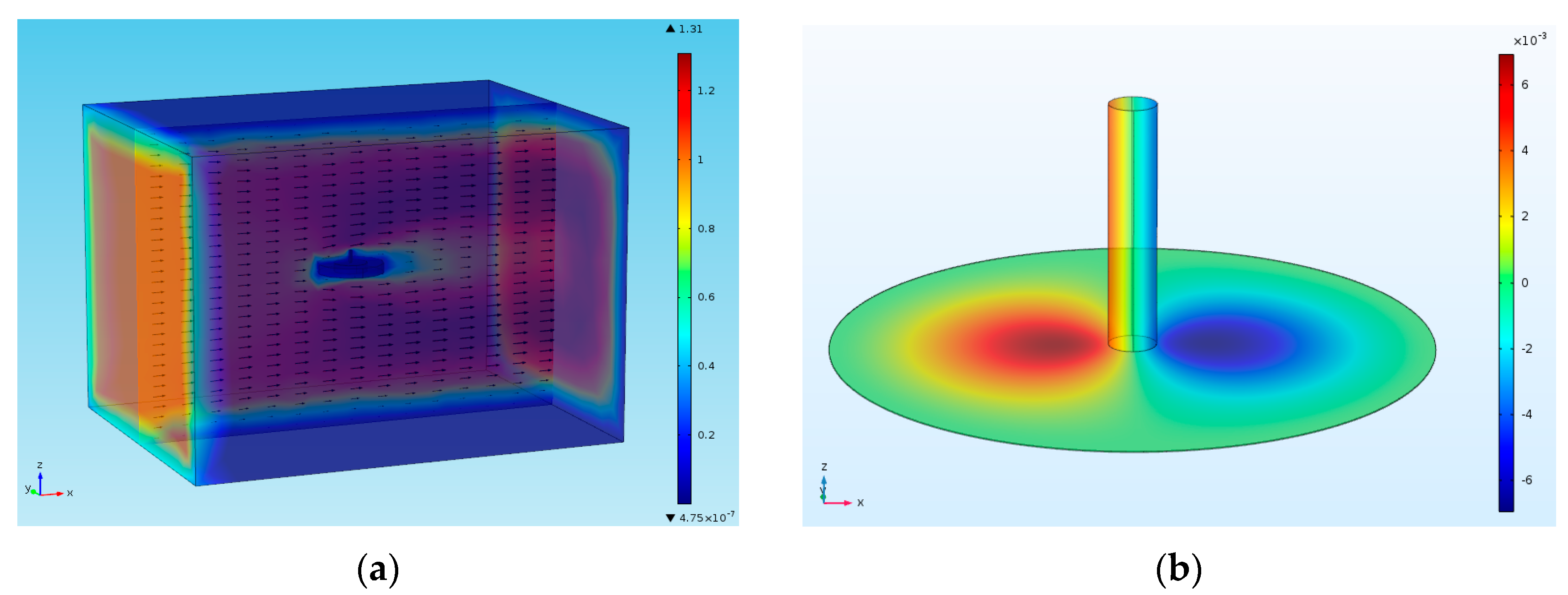
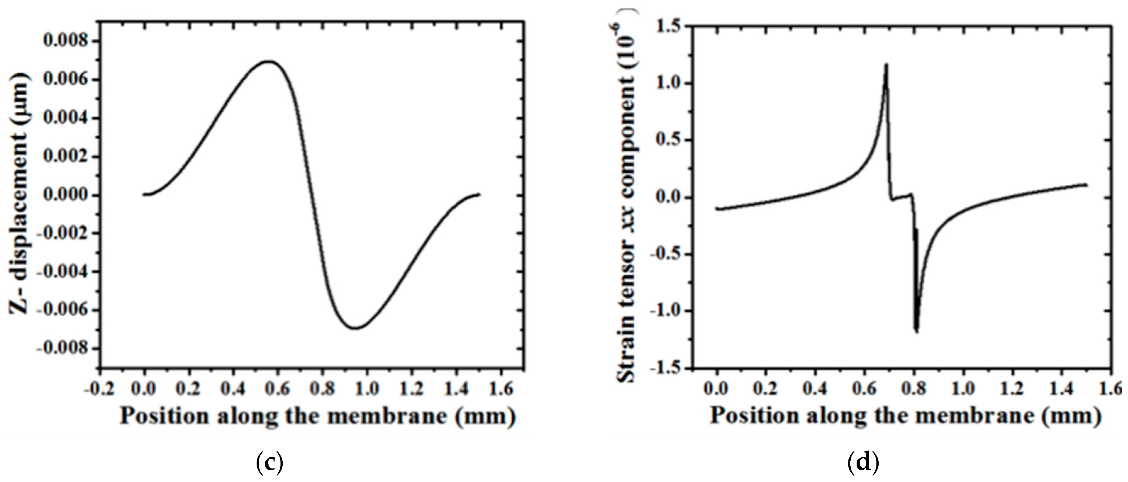
3.2. Design
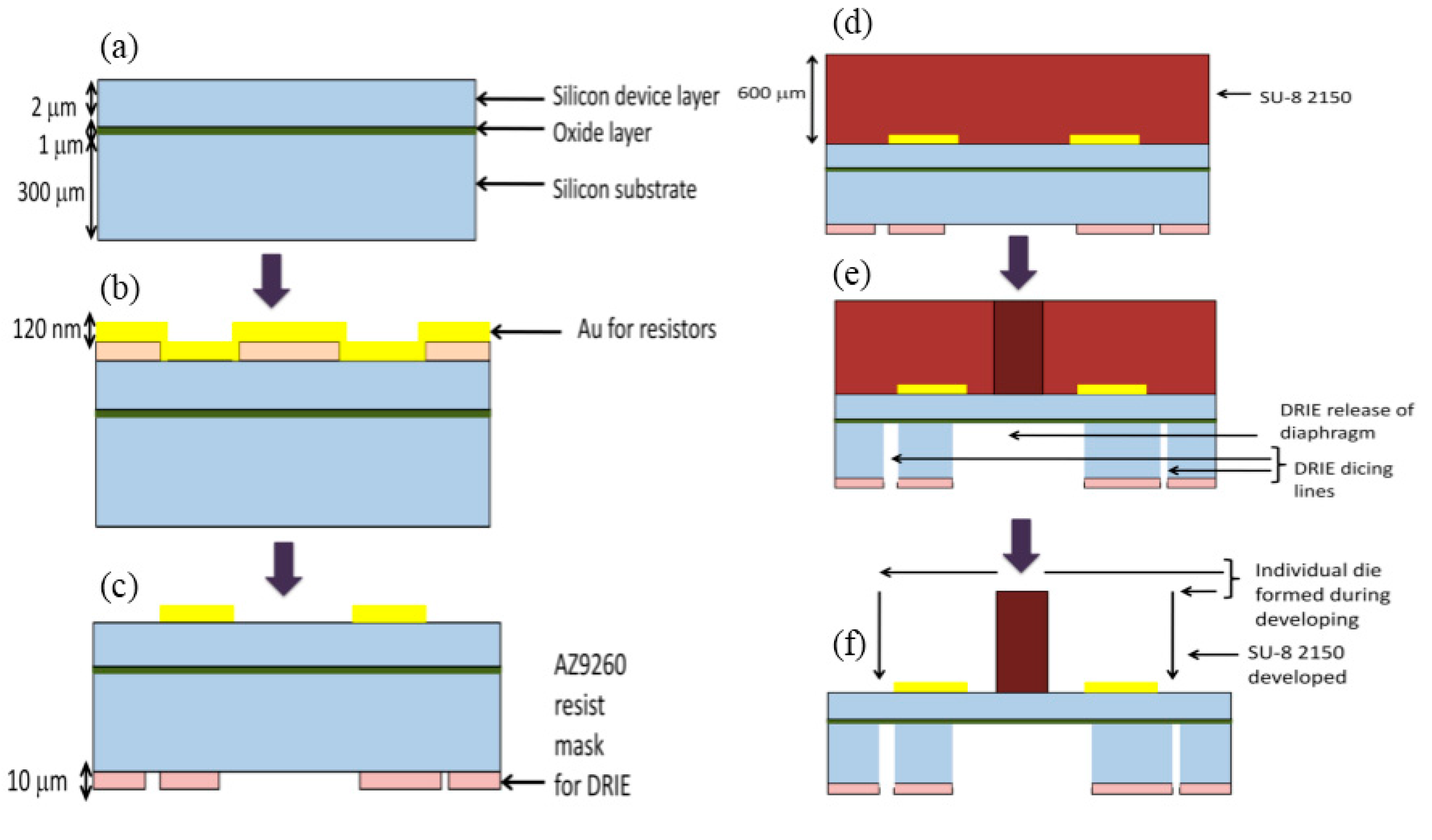
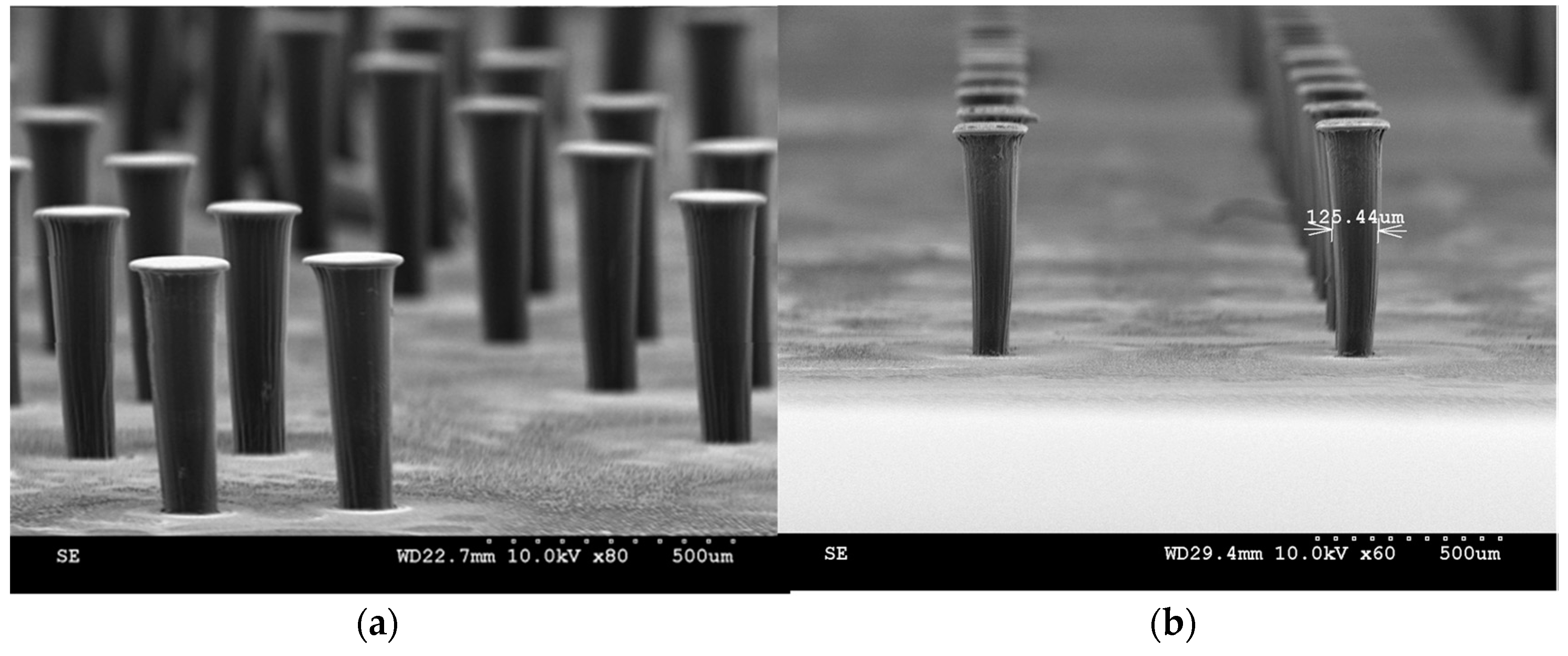
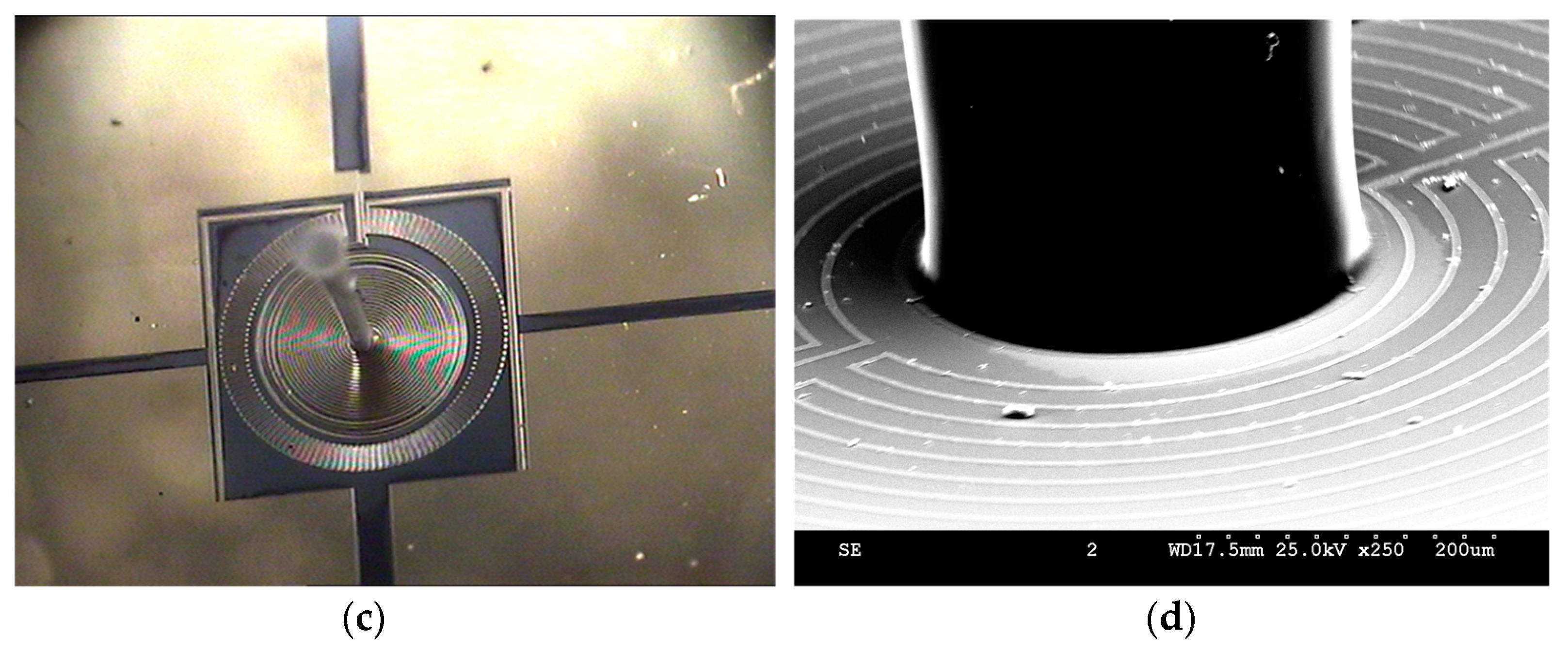
3.3. Fabrication
4. Biomimetic Hydrogel Cupula
4.1. Synthesis of HA Hydrogel Cupula
4.2. Encapsulation Technique
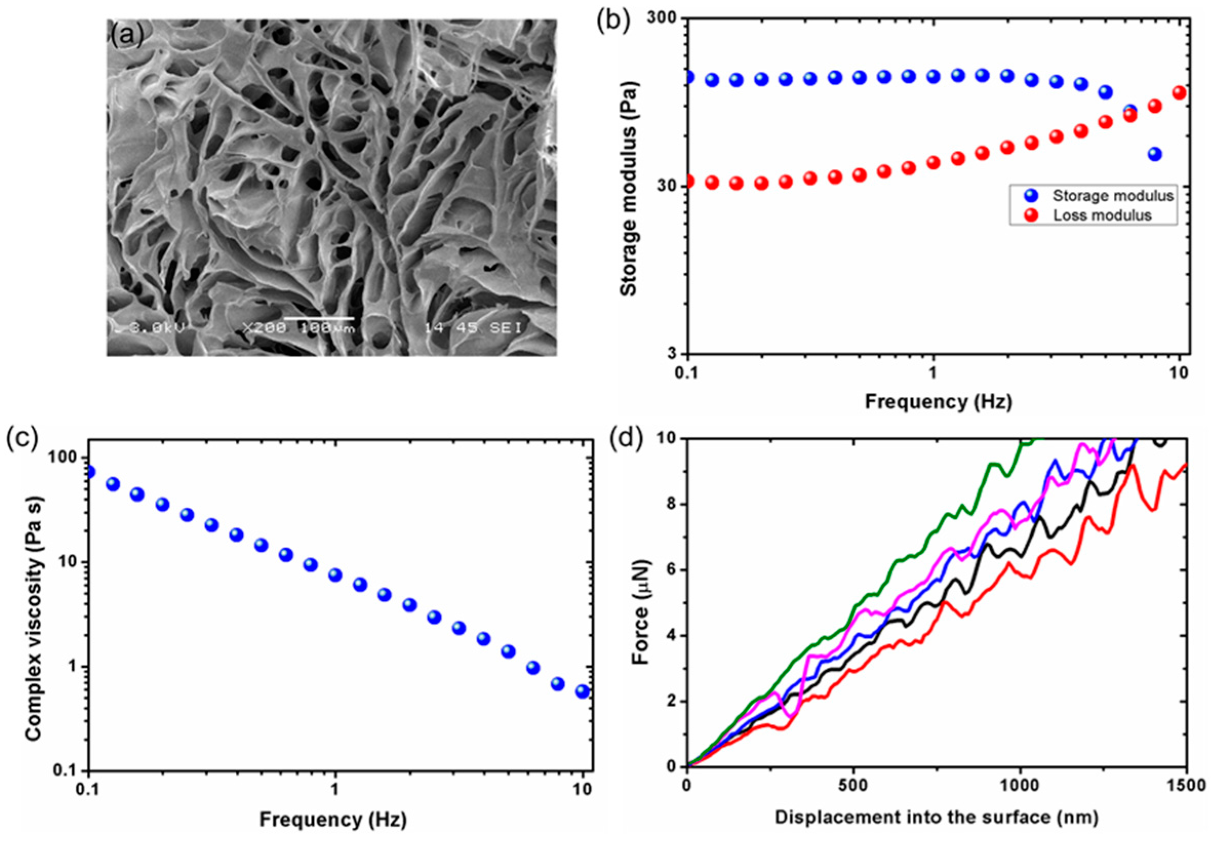
4.3. Hydrogel Characterization
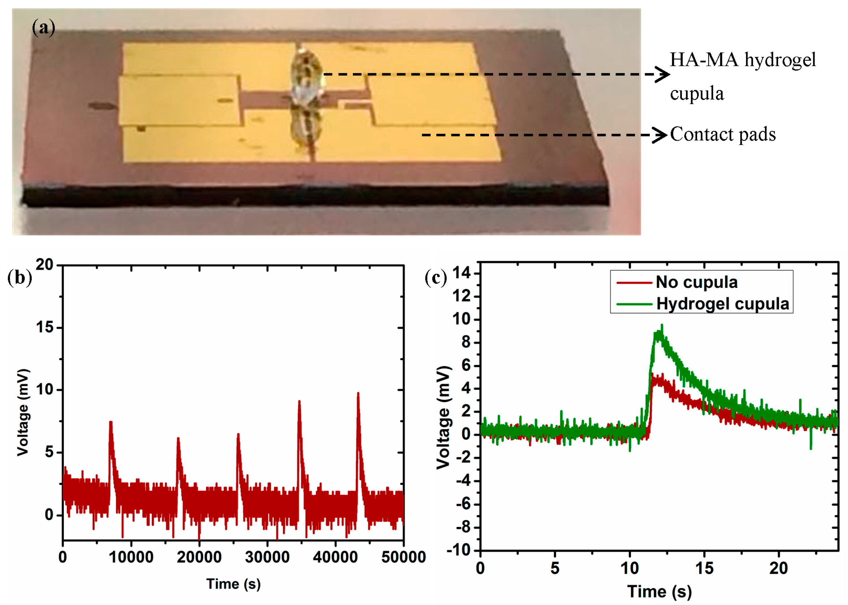
5. Experimental Results
6. Discussion and Conclusions
Acknowledgments
Author Contributions
Conflicts of Interest
References
- Bhushan, B. Biomimetics: Lessons from nature—An overview. Philos. Trans. A Math. Phys. Eng. Sci. 2007, 367, 1445–1486. [Google Scholar] [CrossRef] [PubMed]
- Wasling, H.B.; Norrsell, U.; Gothner, K.; Olausson, H. Tactile directional sensitivity and postural control. Exp. Brain Res. 2005, 166, 147–156. [Google Scholar] [CrossRef] [PubMed]
- Barth, F.G. A Spiders World: Senses and Behavior; Springer: New York, NY, USA, 2002. [Google Scholar]
- Terashima, S.; Goris, R.C. Infrared Receptors and the Trigeminal Sensory System; Harwood: Amsterdam, The Netherlands, 1999. [Google Scholar]
- Dehnhardt, G.; Mauck, B.; Bleckmann, H. Seal whiskers detect water movements. Nature 1998, 394, 235–236. [Google Scholar] [CrossRef]
- Montgomery, J.C.; Baker, C.F.; Carton, A.G. The lateral-line can mediate rheotaxis in fish. Nature 1997, 389, 960–963. [Google Scholar] [CrossRef]
- Montgomery, J.C.; Coombs, S.; Baked, C.F. The mechanosensory lateral line system of the hypogean form of Astyanax fasciatus. Environ. Biol. Fishes 2001, 62, 87–96. [Google Scholar] [CrossRef]
- Coombs, S. Smart Skins: Information processing by lateral line flow sensors. Auton. Robot. 2011, 11, 255–261. [Google Scholar] [CrossRef]
- Teyke, T. Morphological differences in neuromasts of the blind cave fish Astyanax hubbsi and the sighted river fish Astyanax mexicanus. Brain Behav. Evol. 1990, 35, 23–30. [Google Scholar] [CrossRef] [PubMed]
- Jielof, R.; Spoor, A.; de Vries, H. The microphone activity of the lateral-line. J. Physiol. 1952, 116, 137–157. [Google Scholar] [CrossRef] [PubMed]
- Kelly, J.P.; van Netten, S.M. Topography and mechanics of the cupula in the fish lateral-line. I. Variation of cupular structure and composition in the three dimensions. J. Morphol. 1991, 207, 23–36. [Google Scholar] [CrossRef] [PubMed]
- McConney, M.E.; Anderson, K.D.; Brott, L.L.; Naik, R.R.; Tsukruk, V.V. Bioinspired material approaches for sensing. Adv. Funct. Mater. 2009, 19, 2527–2544. [Google Scholar] [CrossRef]
- Engel, J.M.; Chen, J.; Chen, N.; Pandya, S.; Liu, C. Development and characterization of an artificial hair cell based on polyurethane elastomer and force sensitive resistors. In Proceedings of the IEEE Sensors Conference, Irvine, CA, USA, 31 October–3 November 2005; pp. 1014–1017. [Google Scholar]
- Kottapalli, A.G.P.; Asadnia, M.; Miao, J.M.; Barbastathis, G.; Triantafyllou, M. A flexible liquid crystal polymer MEMS pressure sensor array for fish-like underwater sensing. Smart Mater. Struct. 2012, 21, 115030. [Google Scholar] [CrossRef]
- Kottapalli, A.G.P.; Asadnia, M.; Miao, J.M.; Barbastathis, G.; Triantafyllou, M. Polymer MEMS pressure sensor arrays for fish-like underwater sensing applications. IET Micro Nano Lett. 2012, 7, 1189–1192. [Google Scholar] [CrossRef]
- Kottapalli, A.G.P.; Tan, C.W.; Olfatnia, M.; Miao, J.M.; Barbastathis, G.; Triantafyllou, M. A liquid crystal polymer membrane MEMS sensor for flow rate and flow direction sensing applications. J. Micromech. Microeng. 2011, 13, 085006. [Google Scholar] [CrossRef]
- Kottapalli, A.G.P.; Asadnia, M.; Miao, J.M.; Barbastathis, G.; Triantafyllou, M. Soft polymer membrane micro-sensor arrays inspired by the mechanosensory lateral line on the blind cavefish. J. Intell. Mater. Syst. Struct. 2015, 26, 38–46. [Google Scholar] [CrossRef]
- Chen, N.; Tucker, C.; Engel, J.M.; Yang, Y.; Pandya, S.; Liu, C. Design and characterization of artificial haircell sensor for flow sensing with ultrahigh velocity and angular sensitivity. J. Microelectromech. Syst. 2007, 16, 999–1014. [Google Scholar] [CrossRef]
- Peleshenko, S.; Julian, M.D.; Ornatska, M.; McConney, M.E.; LeMieux, M.C.; Chen, N.; Tucker, C.; Yang, Y.; Liu, C.; Humphrey, J.A.C.; et al. Hydrogel-encapsulated microfabricated hair cells mimicking fish cupula neuromast. Adv. Mater. 2007, 19, 2903–2909. [Google Scholar] [CrossRef]
- McConney, M.E.; Chen, N.; Lu, D.; Hu, H.A.; Coombs, S.; Liu, C.; Tsukruk, V.V. Biologically inspired design of hydrogel-capped hair sensors for enhanced underwater flow detection. Soft Matter 2009, 5, 292–295. [Google Scholar] [CrossRef]
- Kottapalli, A.G.P.; Asadnia, M.; Miao, J.M.; Triantafyllou, M. Touch at a distance sensing: Lateral-Line inspired MEMS flow sensors. Bioinspir. Biomim. 2014, 9, 046011. [Google Scholar] [CrossRef] [PubMed]
- Kottapalli, A.G.P.; Asadnia, M.; Miao, J.M.; Triantafyllou, M.S. Electrospun nanofibrils encapsulated in hydrogel cupula for biomimetic MEMS flow sensor development. In Proceedings of the 26th International Conference on Micro Electro Mechanical Systems (MEMS), Taipei, Taiwan, 22–24 January 2013; IEEE: Washington, DC, USA, 2013. [Google Scholar]
- Kottapalli, A.G.P.; Bora, M.; Asadnia, M.; Miao, J.; Venkatraman, S.S.; Triantafyllou, M. Nanofibril scaffold assisted MEMS artificial hydrogel neuromasts for enhanced sensitivity flow sensing. Sci. Rep. 2016, 6, 19336. [Google Scholar] [CrossRef] [PubMed]
- Asadnia, M.; Kottapalli, A.G.P.; Karavitaki, K.D.; Warkiani, M.E.; Miao, J.M.; Corey, D.P. From Biological Cilia to Artificial Flow Sensors: Biomimetic Soft Polymer Nanosensors with High Sensing Performance. Sci. Rep. 2016, 6, 32955. [Google Scholar] [CrossRef] [PubMed]
- Asadnia, M.; Kottapalli, A.G.P.; Shen, Z.; Miao, J.M.; Triantafyllou, M.S. Flexible and surface mountable piezoelectric sensor arrays for underwater sensing in marine vehicles. IEEE Sens. J. 2013, 13, 3918–3925. [Google Scholar] [CrossRef]
- Asadnia, M.; Kottapalli, A.G.P.; Miao, J.M.; Randles, A.B.; Sabbagh, A.; Kropelnicki, P.; Tsai, J.M. High temperature characterization of PZT(0.52/0.48) thin-film pressure sensors. J. Micromech. Microeng. 2014, 24, 015017. [Google Scholar]
- Kottapalli, A.G.P.; Asadnia, M.; Hans, H.; Miao, J.M.; Triantafyllou, M.S. Harbor seal whisker inspired flow sensor to reduce vortex induced vibrations. In Proceedings of the 28th International Conference on Micro Electro Mechanical Systems (MEMS), Estoril, Portugal, 18–22 January 2014; pp. 889–892. [Google Scholar]
- Dijkstra, M.; van Baar, J.J.; Wiegerink, R.J.; Lammerink, T.S.J.; de Boer, J.H.; Krijnen, G.J.M. Artificial sensory hairs based on the flow sensitive receptor hairs of the crickets. J. Micromech. Microeng. 2005, 15, S132–S138. [Google Scholar] [CrossRef]
- Klein, A.; Bleckmann, H. Determination of object position, vortex shedding frequency and flow velocity using artificial lateral line canals. Beilstein J. Nanotechnol. 2011, 2, 276–283. [Google Scholar] [CrossRef] [PubMed]
- Abdulsadda, A.T.; Tan, X. An artificial lateral line system using IPMC sensor arrays. Int. J. Smart Nano Mater. 2012, 3, 226–242. [Google Scholar] [CrossRef]
- Yilmazoglu, O.; Yadav, S.; Cicek, D.; Schneider, J.J. A nano-microstructured artificial-hair-cell-type sensor based on topologically graded 3D carbon nanotube bundles. Nanotechnology 2016, 27, 365502. [Google Scholar] [CrossRef] [PubMed]
- Qualtieri, A.; Rizzi, F.; Epifani, G.; Ernits, A.; Kruusmaa, M.; De Vittorio, M. Parylene coated bioinspired artificial hair cell for liquid flow sensing. Microelectron. Eng. 2012, 98, 516–519. [Google Scholar] [CrossRef]
- Yang, Y.C.; Chen, J.; Engel, J.; Pandya, S.; Chen, N.; Tucker, C.; Coombs, S.; Jones, D.L.; Liu, C. Distant touch hydrodynamic imaging with an artificial lateral line. Proc. Natl. Acad. Sci. USA 2006, 103, 18891–18895. [Google Scholar] [CrossRef] [PubMed]
- Yang, Y.C.; Klein, A.; Bleckmenn, H.; Liu, C. Artificial lateral line canal for hydrodynamic detection. Appl. Phys. Lett. 2011, 99, 023701. [Google Scholar] [CrossRef]
- Abels, C.; Qualtieri, A.; De Vittorio, M.; Megill, W.M.; Rizzi, F. A bio-inspired real-time capable artificial lateral line system for freestream flow measurements. Bioinspir. Biomimet. 2016, 11, 035006. [Google Scholar] [CrossRef] [PubMed]
- Tao, J.; Yu, X.B. Hair flow sensors: From bio-inspiration to bio-mimicking—A review. Smart Mater Struct. 2012, 21, 113001. [Google Scholar] [CrossRef]
- Rizzi, F.; Qualtieri, A.; Dattoma, T.; Epifani, G.; De Vittorio, M. Biomimetics of underwater hair cell sensing. Microelectron. Eng. 2015, 132, 90–97. [Google Scholar] [CrossRef]
- Liu, G.; Wang, A.; Wang, X.; Liu, P. A review of artificial lateral line in sensor fabrication and bionic applications for robot fish. Appl. Bionics Biomech. 2016, 2016. [Google Scholar] [CrossRef] [PubMed]
- Schomburg, W.K.; Rummler, Z.; Shao, P.; Wuff, K.; Xie, L. The design of metal strain gauges on diaphragms. J. Micromech. Microeng. 2004, 14, 1101–1108. [Google Scholar] [CrossRef]
- Smeds, K.A.; Pfister-Serres, A.; Miki, D.; Dastgheib, K.; Inoue, M.; Hatchell, D.L.; Grinstaff, M.W. Photocrosslinkable polysaccharides for in situ hydrogel formation. J. Biomed. Mater Res. 2000, 54, 115–121. [Google Scholar] [CrossRef]
- Baier, L.J.; Bivens, K.A.; Patrick, C.W., Jr.; Schmidt, C.E. Photocrosslinked Hyaluronic Acid Hydrogels: Natural, Biodegradable Tissue Engineering Scaffolds. Biotechnol. Bioeng. 2003, 82, 578–589. [Google Scholar] [CrossRef] [PubMed]
- Anderson, K.D.; Lu, D.; McConney, M.E.; Han, T.; Reneker, D.H.; Tsukruk, V.V. Hydrogel microstructures combined with electrospun fibers and photopatterning for shape and modulus control. Polymer 2008, 49, 5284–5293. [Google Scholar] [CrossRef]


| Parameter | Value |
|---|---|
| Swelling ratio | 37.4 |
| Equilibrium water content | 85% |
| Crosslinking density | 2.5 × 10⁻⁶ mol/cm3 |
| Mesh size | 433 nm |
© 2017 by the authors. Licensee MDPI, Basel, Switzerland. This article is an open access article distributed under the terms and conditions of the Creative Commons Attribution (CC BY) license (http://creativecommons.org/licenses/by/4.0/).
Share and Cite
Kottapalli, A.G.P.; Bora, M.; Kanhere, E.; Asadnia, M.; Miao, J.; Triantafyllou, M.S. Cupula-Inspired Hyaluronic Acid-Based Hydrogel Encapsulation to Form Biomimetic MEMS Flow Sensors. Sensors 2017, 17, 1728. https://doi.org/10.3390/s17081728
Kottapalli AGP, Bora M, Kanhere E, Asadnia M, Miao J, Triantafyllou MS. Cupula-Inspired Hyaluronic Acid-Based Hydrogel Encapsulation to Form Biomimetic MEMS Flow Sensors. Sensors. 2017; 17(8):1728. https://doi.org/10.3390/s17081728
Chicago/Turabian StyleKottapalli, Ajay Giri Prakash, Meghali Bora, Elgar Kanhere, Mohsen Asadnia, Jianmin Miao, and Michael S. Triantafyllou. 2017. "Cupula-Inspired Hyaluronic Acid-Based Hydrogel Encapsulation to Form Biomimetic MEMS Flow Sensors" Sensors 17, no. 8: 1728. https://doi.org/10.3390/s17081728