Thermal Flow Sensors for Harsh Environments

 ,
,  ,
, 

Abstract
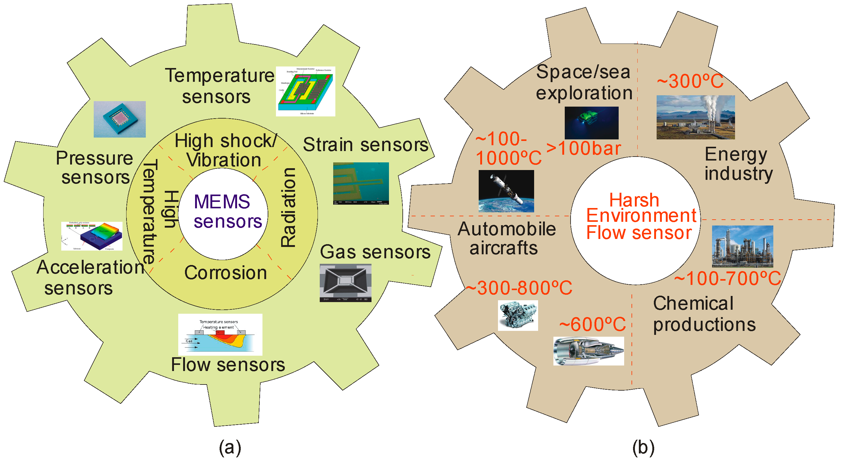
1. Introduction
2. Thermal Flow Sensors and Their Operation
2.1. Theory
2.1.1. Hot-Wire and Hot-Film Flow Sensors
2.1.2. Calorimetric Configuration
2.1.3. Time of Flight Flow Sensor
3. Transduction Mechanisms of Thermal Flow Sensors
3.1. Thermoelectric Flow Sensing
3.2. Thermoresistive Flow Sensing
3.3. Thermoelectronic Flow Sensing
4. State of the Art Materials and Properties for Harsh Environments
4.1. Heating and Sensing Materials
4.1.1. Metals and Alloys
4.1.2. Semiconductors
4.1.3. Polymers
4.1.4. Ceramics
4.2. Insulating Substrate Materials
5. Recent Thermal Flow Sensors
5.1. Thermoelectric Flow Sensors
5.2. Thermoresistive Flow Sensors
5.3. Thermoelectronic Flow Sensors
6. Packaging of Thermal Flow Sensors in Harsh Environments
6.1. Substrate Material Properties
6.2. Metallization
6.3. Die-Attach and Hermeticity
6.4. Protective Coatings
6.5. Signal Processing and Electronic Circuitry
6.6. Recent Packaging Strategies of Thermal Flow Sensors
7. Conclusions and Future Challenges
Acknowledgments
Author Contributions
Conflicts of Interest
References
- French, P.; Krijnen, G.; Roozeboom, F. Precision in harsh environments. Microsyst. Nanoeng. 2016, 2. [Google Scholar] [CrossRef]
- Vivekananathan, B.; Ponnusamy, L.; Thiruppathi, K. Design and optimization of multivariable controller for CSTR system. In Proceedings of the 2015 International Conference on Robotics, Automation, Control and Embedded Systems (RACE), Chennai, India, 18–20 Feburary 2015; pp. 1–5. [Google Scholar]
- Thiruppathi, K.; Ponnusamy, L.; Vivekananathan, B. Design and tuning of decoupled PI controllers for real time deep-sea conditions mimicking system. In Proceedings of the 2015 International Conference on Robotics, Automation, Control and Embedded Systems (RACE), Chennai, India, 18–20 Feburary 2015. [Google Scholar]
- Okojie, R.S.; Ned, A.A.; Kurtz, A.D. Operation of α (6H)-SiC pressure sensor at 500 °C. Sens. Actuators A Phys. 1998, 66, 200–204. [Google Scholar] [CrossRef]
- Ziermann, R.; von Berg, J.; Reichert, W.; Obermeier, E.; Eickhoff, M.; Krotz, G. A high temperature pressure sensor with/spl beta/-SiC piezoresistors on SOI substrates. In Proceedings of the 1997 International Conference on Solid State Sensors and Actuators (TRANSDUCERS’97), Chicago, IL, USA, 16–19 June 1997; pp. 1411–1414. [Google Scholar]
- Krotz, G. New harsh environment sensor designs based on silicon carbide. MST News 1997, 21, 17. [Google Scholar]
- Nagai, T.; Itoh, M. SiC thin-film thermistors. IEEE Trans. Ind. Appl. 1990, 26, 1139–1143. [Google Scholar] [CrossRef]
- Kamimura, K.; Miwa, T.; Sugiyama, T.; Ogawa, T.; Nakao, M.; Onuma, Y. Preparation of polycrystalline SiC thin films and its application to resistive sensors. Silicon Carbide Relat. Mater. 1995 1996, 142, 825–828. [Google Scholar]
- Arbab, A.; Spetz, A.; Lundström, I. Gas sensors for high temperature operation based on metal oxide silicon carbide (MOSiC) devices. Sens. Actuators B Chem. 1993, 15, 19–23. [Google Scholar] [CrossRef]
- Arbab, A.; Spetz, A.; Lundström, I. Evaluation of gas mixtures with high-temperature gas sensors based on silicon carbide. Sens. Actuators B Chem. 1994, 19, 562–565. [Google Scholar] [CrossRef]
- Baranzahi, A.; Spetz, A.L.; Andersson, B.; Lundström, I. Gas sensitive field effect devices for high temperature. Sens. Actuators B Chem. 1995, 26, 165–169. [Google Scholar] [CrossRef]
- Hunter, G.; Neudeck, P.; Chen, L.; Knight, D.; Liu, C.; Wu, Q. Silicon carbide-based detection of hydrogen and hydrocarbons. Silicon Carbde Relat. Mater. 1995 1996, 142, 817–820. [Google Scholar]
- Shields, V.; Ryan, M.A.; Williams, R.M.; Spencer, M.G.; Collins, D.M.; Zhang, D. A Variable Potential Porous Silicon Carbide Hydrocarbon Gas Sensor; NASA: Washington, DC, USA, 1995. [Google Scholar]
- Azevedo, R.G.; Jones, D.G.; Jog, A.V.; Jamshidi, B.; Myers, D.R.; Chen, L.; Fu, X.-A.; Mehregany, M.; Wijesundara, M.B.; Pisano, A.P. A SiC MEMS resonant strain sensor for harsh environment applications. IEEE Sens. J. 2007, 7, 568–576. [Google Scholar] [CrossRef]
- Azevedo, R.G.; Zhang, J.; Jones, D.G.; Myers, D.R.; Jog, A.V.; Jamshidi, B.; Wijesundara, M.B.; Maboudian, R.; Pisano, A.P. Silicon carbide coated MEMS strain sensor for harsh environment applications. In Proceedings of the IEEE 20th International Conference on Micro Electro Mechanical Systems (MEMS), Hyogo, Japan, 21–25 January 2007; pp. 643–646. [Google Scholar]
- Jamshidi, B.; Azevedo, R.G.; Wijesundara, M.B.; Pisano, A.P. Corrosion enhanced capacitive strain gauge at 370 °C. In Proceedings of the 2007 IEEE Sensors, Atlanta, GA, USA, 28–31 October 2007; pp. 804–807. [Google Scholar]
- Jamshidi, B. Poly-Crystalline Silicon Carbide Passivated Capacitive Mems Strain Gauge for Harsh Environments; University of California: Berkeley, CA, USA, 2008. [Google Scholar]
- Brown, T.G. Harsh military environments and microelectromechanical (MEMS) devices. In Proceedings of the 2003 IEEE Sensors, Toronto, ON, Canada, 22–24 October 2003; pp. 753–760. [Google Scholar]
- Atwell, A.R.; Okojie, R.S.; Kornegay, K.T.; Roberson, S.L.; Beliveau, A. Simulation, fabrication and testing of bulk micromachined 6H-SiC high-g piezoresistive accelerometers. Sens. Actuators A Phys. 2003, 104, 11–18. [Google Scholar] [CrossRef]
- Jiang, X.; Kim, K.; Zhang, S.; Johnson, J.; Salazar, G. High-temperature piezoelectric sensing. Sensors 2013, 14, 144–169. [Google Scholar] [CrossRef] [PubMed]
- Wijesundara, M.; Azevedo, R. Silicon Carbide Microsystems for Harsh Environments; Springer Science & Business Media: Berlin, Germany, 2011; Volume 22. [Google Scholar]
- Bruschi, P.; Piotto, M. Design issues for low power integrated thermal flow sensors with ultra-wide dynamic range and low insertion loss. Micromachines 2012, 3, 295–314. [Google Scholar] [CrossRef]
- Van Putten, A.; Middelhoek, S. Integrated silicon anemometer. Electron. Lett. 1974, 10, 425–426. [Google Scholar] [CrossRef]
- Nguyen, N.; Dötzel, W. Asymmetrical locations of heaters and sensors relative to each other using heater arrays: A novel method for designing multi-range electrocaloric mass-flow sensors. Sens. Actuators A Phys. 1997, 62, 506–512. [Google Scholar] [CrossRef]
- Phan, H.-P.; Dao, D.V.; Nakamura, K.; Dimitrijev, S.; Nguyen, N.-T. The piezoresistive effect of SiC for MEMS sensors at high temperatures: A review. J. Microelectromec. Syst. 2015, 24, 1663–1677. [Google Scholar] [CrossRef]
- Werner, M.R.; Fahrner, W.R. Review on materials, microsensors, systems and devices for high-temperature and harsh-environment applications. IEEE Trans. Ind. Electron. 2001, 48, 249–257. [Google Scholar] [CrossRef]
- Silvestri, S.; Schena, E. Micromachined flow sensors in biomedical applications. Micromachines 2012, 3, 225–243. [Google Scholar] [CrossRef]
- Van Oudheusden, B. Silicon thermal flow sensors. Sens. Actuators A Phys. 1992, 30, 5–26. [Google Scholar] [CrossRef]
- Khamshah, N.; Abdalla, A.N.; Koh, S.; Rashag, H.F. Issues and temperature compensation techniques for hot wire thermal flow sensor: A review. Int. J. Phys. Sci. 2011, 6, 3270–3327. [Google Scholar]
- Dinh, T.; Phan, H.-P.; Dao, D.V.; Woodfield, P.; Qamar, A.; Nguyen, N.-T. Graphite on paper as material for sensitive thermoresistive sensors. J. Mater. Chem. C 2015, 3, 8776–8779. [Google Scholar] [CrossRef]
- Nguyen, N.-T. A novel thermal sensor concept for flow direction and flow velocity. IEEE Sens. J. 2005, 5, 1224–1234. [Google Scholar] [CrossRef]
- Gravenstein, J.S.; Jaffe, M.B.; Gravenstein, N.; Paulus, D.A. Capnography; Cambridge University Press: Cambridge, UK, 2011. [Google Scholar]
- King, L.V. On the convection of heat from small cylinders in a stream of fluid: Determination of the convection constants of small platinum wires with applications to hot-wire anemometry. Philos. Trans. R. Soc. Lond. Ser. A Contain. Pap. Math. Phys. Character 1914, 214, 373–432. [Google Scholar] [CrossRef]
- Takagi, S. A hot-wire anemometer compensated for ambient temperature variations. J. Phys. E Sci. Instrum. 1986, 19, 739. [Google Scholar] [CrossRef]
- Freymuth, P. On Feedback Control Theory for Constant Temperature Hot Wire Anemometers. Rev. Sci. Instrum. 1972, 43, 704–705. [Google Scholar] [CrossRef]
- Zhu, Y.; Chen, B.; Qin, M.; Huang, Q.-A. 2-D micromachined thermal wind sensors—A review. IEEE Int. Things J. 2014, 1, 216–232. [Google Scholar] [CrossRef]
- Ferreira, R.P.C.; Freire, R.C.S.; Deep, C.; de Rocha Neto, J.S.; Oliveira, A. Hot-wire anemometer with temperature compensation using only one sensor. IEEE Trans. Instrum. Meas. 2001, 50, 954–958. [Google Scholar] [CrossRef]
- Beeby, S. MEMS Mechanical Sensors; Artech House: London, UK, 2004. [Google Scholar]
- Dinh, T.; Phan, H.-P.; Nguyen, T.-K.; Qamar, A.; Woodfield, P.; Zhu, Y.; Nguyen, N.-T.; Dao, D.V. Solvent-free fabrication of biodegradable hot-film flow sensor for noninvasive respiratory monitoring. J. Phys. D Appl. Phys. 2017, 50, 215401. [Google Scholar] [CrossRef]
- Furuichi, T.; Nagao, T.; Yokura, H.; Abe, R.; Fukatsu, S. Thin-Film Air Flow Sensors for Automotive using the MEMS Technologies. SAE Int. J. Passeng. Cars-Electron. Electr. Syst. 2015, 8, 314–319. [Google Scholar] [CrossRef]
- Nguyen, N. Micromachined flow sensors—A review. Flow Meas. Instrum. 1997, 8, 7–16. [Google Scholar] [CrossRef]
- Elwenspoek, M.; Wiegerink, R. Mechanical Microsensors; Springer Science & Business Media: Berlin, Germany, 2012. [Google Scholar]
- Sabaté, N.; Santander, J.; Fonseca, L.; Gràcia, I.; Cané, C. Multi-range silicon micromachined flow sensor. Sens. Actuators A Phys. 2004, 110, 282–288. [Google Scholar] [CrossRef]
- Lei, M.I. Silicon Carbide High Temperature Thermoelectric Flow Sensor. Ph.D. Thesis, Case Western Reserve University, Cleveland, OH, USA, 2010. [Google Scholar]
- Fürjes, P.; Légrádi, G.; Dücső, C.; Aszódi, A.; Bársony, I. Thermal characterisation of a direction dependent flow sensor. Sens. Actuators A Phys. 2004, 115, 417–423. [Google Scholar] [CrossRef]
- Lekholm, V.; Persson, A.; Palmer, K.; Ericson, F.; Thornell, G. High-temperature zirconia microthruster with an integrated flow sensor. J. Micromech. Microeng. 2013, 23, 055004. [Google Scholar] [CrossRef]
- Palmer, K.; Kratz, H.; Nguyen, H.; Thornell, G. A highly integratable silicon thermal gas flow sensor. J. Micromech. Microeng. 2012, 22, 065015. [Google Scholar] [CrossRef]
- De Luca, A.; Haneef, I.; Coull, J.D.; Ali, S.Z.; Falco, C.; Udrea, F. High-Sensitivity Single Thermopile SOI CMOS MEMS Thermal Wall Shear Stress Sensor. IEEE Sens. J. 2015, 15, 5561–5568. [Google Scholar] [CrossRef]
- Van Kuijk, J.; Lammerink, T.; De Bree, H.-E.; Elwenspoek, M.; Fluitman, J. Multi-parameter detection in fluid flows. Sens. Actuators A Phys. 1995, 47, 369–372. [Google Scholar] [CrossRef]
- Moazzeni, T.; Ma, J.; Jiang, Y.; Li, N. Flow rate measurement in a high-temperature, radioactive, and corrosive environment. IEEE Trans. Instrum. Meas. 2011, 60, 2062–2069. [Google Scholar] [CrossRef]
- Yan-bin, D.; Ying, M. RETRACTED: Quick, Temperature Independent Flow Sensor. Procedia Eng. 2011, 15, 4636–4640. [Google Scholar] [CrossRef]
- Sosna, C.; Kropp, M.; Lang, W.; Buchner, R. Miniaturized thermal flow sensors with through silicon vias for flip-chip packaging. In Proceedings of the 2010 IEEE Sensors, Aikoloa, HI, USA, 1–4 November 2010; pp. 2460–2463. [Google Scholar]
- Dinh, T.; Phan, H.-P.; Qamar, A.; Woodfield, P.; Nguyen, N.-T.; Dao, D.V. Thermoresistive Effect for Advanced Thermal Sensors: Fundamentals, Design Considerations, and Applications. J. Microelectromec. Syst. 2017, PP, 1–21. [Google Scholar] [CrossRef]
- Korvink, J.; Paul, O. MEMS: A Practical Guide of Design, Analysis, and Applications; Springer Science & Business Media: Berlin, Germany, 2010. [Google Scholar]
- Nguyen, N.T.; Wereley, S.T. Fundamentals and Applications of Microfluidics; Artech House: London, UK, 2002. [Google Scholar]
- Weide-Zaage, K.; Chrzanowska-Jeske, M. Semiconductor Devices in Harsh Conditions; CRC Press: Boca Raton, FL, USA, 2016. [Google Scholar]
- Boltovets, N.; Kholevchuk, V.; Konakova, R.; Mitin, V.; Venger, E. Ge-film resistance and Si-based diode temperature microsensors for cryogenic applications. Sens. Actuators A Phys. 2001, 92, 191–196. [Google Scholar] [CrossRef]
- Zhang, N.; Lin, C.-M.; Senesky, D.G.; Pisano, A.P. Temperature sensor based on 4H-silicon carbide pn diode operational from 20 °C to 600 °C. Appl. Phys. Lett. 2014, 104, 073504. [Google Scholar] [CrossRef]
- Luther, B.; Wolter, S.; Mohney, S. High temperature Pt Schottky diode gas sensors on n-type GaN. Sens. Actuators B Chem. 1999, 56, 164–168. [Google Scholar] [CrossRef]
- Casady, J.; Johnson, R.W. Status of silicon carbide (SiC) as a wide-bandgap semiconductor for high-temperature applications: A review. Solid-State Electron. 1996, 39, 1409–1422. [Google Scholar] [CrossRef]
- Neudeck, P.G.; Garverick, S.L.; Spry, D.J.; Chen, L.Y.; Beheim, G.M.; Krasowski, M.J.; Mehregany, M. Extreme temperature 6H-SiC JFET integrated circuit technology. Phys. Status Solidi 2009, 206, 2329–2345. [Google Scholar] [CrossRef]
- Lin, B. Microfluidics: Technologies and Applications; Springer: Berlin, Germany, 2011; Volume 304. [Google Scholar]
- Berlicki, T.; Murawski, E.; Osadnik, S.; Prociòw, E. Thermoresistive thin film flow sensor. Act. Passive Electron. Comp. 1989, 13, 161–173. [Google Scholar] [CrossRef]
- Buchner, R.; Bhargava, P.; Sosna, C.; Benecke, W.; Lang, W. Thermoelectric flow sensors with monolithically integrated channel structures for measurements of very small flow rates. In Proceedings of the 2007 IEEE Sensors, Atlanta, GA, USA, 21–28 October 2007; pp. 828–831. [Google Scholar]
- Buchner, R.; Froehner, K.; Sosna, C.; Benecke, W.; Lang, W. Toward flexible thermoelectric flow sensors: A new technological approach. J. Microelectromec. Syst. 2008, 17, 1114–1119. [Google Scholar] [CrossRef]
- Ghodssi, R.; Lin, P. MEMS Materials and Processes Handbook; Springer Science & Business Media: Berlin, Germany, 2011; Volume 1. [Google Scholar]
- Sharpe, W.N., Jr. Mechanical Properties of MEMS Materials. In The MEMS Handbook; CRC Press: Boca Raton, FL, USA, 2001. [Google Scholar]
- Billat, S.; Storz, M.; Ashauer, H.; Hedrich, F.; Kattinger, G.; Lust, L.; Ashauer, M.; Zengerle, R. Thermal flow sensors for harsh environment applications. Procedia Chem. 2009, 1, 1459–1462. [Google Scholar] [CrossRef]
- Zhang, J.; Carraro, C.; Howe, R.T.; Maboudian, R. Electrical, mechanical and metal contact properties of polycrystalline 3C-SiC films for MEMS in harsh environments. Surf. Coat. Technol. 2007, 201, 8893–8898. [Google Scholar] [CrossRef]
- Kohl, F.; Fasching, R.; Keplinger, F.; Chabicovsky, R.; Jachimowicz, A.; Urban, G. Development of miniaturized semiconductor flow sensors. Measurement 2003, 33, 109–119. [Google Scholar] [CrossRef]
- Mailly, F.; Giani, A.; Bonnot, R.; Temple-Boyer, P.; Pascal-Delannoy, F.; Foucaran, A.; Boyer, A. Anemometer with hot platinum thin film. Sens. Actuators A Phys. 2001, 94, 32–38. [Google Scholar] [CrossRef]
- Vereshchagina, E.; Wolters, R.; Gardeniers, J. Measurement of reaction heats using a polysilicon-based microcalorimetric sensor. Sens. Actuators A Phys. 2011, 169, 308–316. [Google Scholar] [CrossRef]
- Liu, L.; Tang, W.; Zheng, B.-X.; Zhang, H.-X. Fabrication and characterization of SiC thin films. In Proceedings of the 2011 IEEE International Conference on Nano/Micro Engineered and Molecular Systems (NEMS), Kaohsiung, Taiwan, 20–23 Feburary 2011; pp. 146–149. [Google Scholar]
- Roy, J.; Chandra, S.; Das, S.; Maitra, S. Oxidation behaviour of silicon carbide—A review. Rev. Adv. Mater. Sci. 2014, 38, 29–39. [Google Scholar]
- Balakrishnan, V.; Dinh, T.; Phan, H.-P.; Kozeki, T.; Namazu, T.; Dao, D.V.; Nguyen, N.-T. Steady-state analytical model of suspended p-type 3C-SiC bridges under consideration of Joule heating. J. Micromech. Microeng. 2017, 27, 075008. [Google Scholar] [CrossRef]
- Phan, H.-P.; Dinh, T.; Kozeki, T.; Qamar, A.; Namazu, T.; Dimitrijev, S.; Nguyen, N.-T.; Dao, D.V. Piezoresistive effect in p-type 3C-SiC at high temperatures characterized using Joule heating. Sci. Rep. 2016, 6, 28499. [Google Scholar] [CrossRef] [PubMed]
- Spannhake, J.; Helwig, A.; Müller, G.; Doll, T. Sic As A High-Performance Material For Microheaters. Available online: http://www.qucosa.de/fileadmin/data/qucosa/documents/2859/7616.pdf#page=32 (accessed on 7 September 2017).
- Zhang, X.; Zhao, L.-D. Thermoelectric materials: Energy conversion between heat and electricity. J. Mater. 2015, 1, 92–105. [Google Scholar] [CrossRef]
- LaLonde, A.D.; Pei, Y.; Wang, H.; Snyder, G.J. Lead telluride alloy thermoelectrics. Mater. Today 2011, 14, 526–532. [Google Scholar] [CrossRef]
- Cassidy, P.E. An overview of polymers for harsh environments; aerospace, geothermal and undersea. In Adhesives, Sealants, and Coatings for Space and Harsh Environments; Springer: Berlin, Germany, 1988. [Google Scholar]
- Jiang, L.; Cheung, R. A review of silicon carbide development in MEMS applications. Int. J. Comput. Mater. Sci. Surf. Eng. 2009, 2, 227–242. [Google Scholar] [CrossRef]
- Aslam, M.; Gregory, C.; Hatfield, J. Polyimide membrane for micro-heated gas sensor array. Sens. Actuators B Chem. 2004, 103, 153–157. [Google Scholar] [CrossRef]
- Buchner, R.; Maiwald, M.; Sosna, C.; Schary, T.; Benecke, W.; Lang, W. Miniaturised thermal flow sensors for rough environments. In Proceedings of the 19th IEEE International Conference on Micro Electro Mechanical Systems (MEMS 2006), Istanbul, Turkey, 22–26 January 2006; pp. 582–585. [Google Scholar]
- Ahrens, R.; Festa, M. Polymer-based micro flow sensor for dynamical flow measurements in hydraulic systems. J. Micromech. Microeng. 2010, 20, 064004. [Google Scholar] [CrossRef]
- Kita, J.; Moos, R. Development of LTCC-materials and Their Applications: An Overview. Inf. MIDEM 2008, 38, 219–224. [Google Scholar]
- Bienert, C.; Roosen, A. Characterization and improvement of LTCC composite materials for application at elevated temperatures. J. Eur. Ceram. Soc. 2010, 30, 369–374. [Google Scholar] [CrossRef]
- Cheah, K.; Khiew, P.; Chin, J. Fabrication of a zirconia MEMS-based microthruster by gel casting on PDMS soft molds. J. Micromech. Microeng. 2012, 22, 095013. [Google Scholar] [CrossRef]
- Gregory, O.J.; You, T. Ceramic temperature sensors for harsh environments. IEEE Sens. J. 2005, 5, 833–838. [Google Scholar] [CrossRef]
- Wang, C.; Akbar, S.; Madou, M. Ceramic based resistive sensors. J. Electroceram. 1998, 2, 273–282. [Google Scholar] [CrossRef]
- Yarali, M.; Khanna, S.K. Microfabrication of a variable range and multi-directionally sensitive thermal flow sensor. Sens. Actuators A Phys. 2014, 220, 159–167. [Google Scholar] [CrossRef]
- Cubukcu, A.S.; Romero, D.F.R.; Urban, G.A. A dynamic thermal flow sensor for simultaneous measurement of thermal conductivity and flow velocity of gases. Sens. Actuators A Phys. 2014, 208, 73–87. [Google Scholar] [CrossRef]
- Sabaté, N.; Santander, J.; Gràcia, I.; Fonseca, L.; Figueras, E.; Cabruja, E.; Cané, C. Characterization of thermal conductivity in thin film multilayered membranes. Thin Solid Films 2005, 484, 328–333. [Google Scholar] [CrossRef]
- Srinivasan, R.; Hsing, I.; Berger, P.E.; Jensen, K.F.; Firebaugh, S.L.; Schmidt, M.A.; Harold, M.P.; Lerou, J.J.; Ryley, J.F. Micromachined reactors for catalytic partial oxidation reactions. AIChE J. 1997, 43, 3059–3069. [Google Scholar] [CrossRef]
- Stoffel, A.; Kovacs, A.; Kronast, W.; Müller, B. LPCVD against PECVD for micromechanical applications. J. Micromech. Microeng. 1996, 6, 1. [Google Scholar] [CrossRef]
- Jing, X.; Lu, J.; Miao, J.; Hans, H.; Rahman, H.; Pan, S.; Norford, L. An aerodynamically efficient sphere anemometer with integrated hot-film sensors for 2-D environmental airflow monitoring. In Proceedings of the 2011 16th International Solid-State Sensors, Actuators and Microsystems Conference (TRANSDUCERS), Beijing, China, 5–9 June 2011; pp. 96–99. [Google Scholar]
- Therdthai, N.; Zhou, W.; Adamczak, T. The development of an anemometer for industrial bread baking. J. Food Eng. 2004, 63, 329–334. [Google Scholar] [CrossRef]
- De Luca, A.; Longobardi, G.; Udrea, F. SOI multidirectional thermoelectric flow sensor for harsh environment applications. In Proceedings of the 2015 International Semiconductor Conference (CAS), Sinaia, Romania, 12–14 October 2015; pp. 95–98. [Google Scholar]
- Buchner, R.; Sosna, C.; Maiwald, M.; Benecke, W.; Lang, W. A high-temperature thermopile fabrication process for thermal flow sensors. Sens. Actuators A Phys. 2006, 130, 262–266. [Google Scholar] [CrossRef]
- Gould, D.; Sturm, H.; Lang, W. Thermoelectric flow sensor integrated into an inductively powered wireless system. IEEE Sens. J. 2012, 12, 1891–1892. [Google Scholar] [CrossRef]
- Laconte, J.; Dupont, C.; Flandre, D.; Raskin, J.-P. SOI CMOS compatible low-power microheater optimization for the fabrication of smart gas sensors. IEEE Sens. J. 2004, 4, 670–680. [Google Scholar] [CrossRef]
- Ritterath, M.; Voser, P.; Dietze, W.; Prasser, H.-M.; Paladino, D. Robust thermal flow sensor for a containment test facility. In Proceedings of the 2009 IEEE Sensors, Hristchurch, New Zealand, 5–28 October 2009; pp. 1419–1422. [Google Scholar]
- Cavicchi, R.E.; Poirier, G.; Tea, N.; Afridi, M.; Berning, D.; Hefner, A.; Suehle, J.; Gaitan, M.; Semancik, S.; Montgomery, C. Micro-differential scanning calorimeter for combustible gas sensing. Sens. Actuators B Chem. 2004, 97, 22–30. [Google Scholar] [CrossRef]
- Bruschi, P.; Diligenti, A.; Navarrini, D.; Piotto, M. A double heater integrated gas flow sensor with thermal feedback. Sens. Actuators A Phys. 2005, 123, 210–215. [Google Scholar] [CrossRef]
- Lyons, C.; Friedberger, A.; Welser, W.; Muller, G.; Krotz, G.; Kassing, R. A high-speed mass flow sensor with heated silicon carbide bridges. In Proceedings of the 1998 Eleventh Annual International Workshop on; Micro Electro Mechanical Systems (MEMS 98), Heidelberg, Germany, 25–29 Januray 1998; pp. 356–360. [Google Scholar]
- Mahdavifar, A.; Aguilar, R.; Peng, Z.; Hesketh, P.J.; Findlay, M.; Stetter, J.R.; Hunter, G.W. Simulation and fabrication of an ultra-low power miniature microbridge thermal conductivity gas sensor. J. Electrochem. Soc. 2014, 161, B55–B61. [Google Scholar] [CrossRef]
- Shim, J.-C.; Chung, G.-S. Fabrication and characteristics of Pt/ZnO NO sensor integrated SiC micro heater. In Proceedings of the 2010 IEEE Sensors, Kona, HI, USA, 1–4 November 2010; pp. 350–353. [Google Scholar]
- Schmid, U. A robust flow sensor for high pressure automotive applications. Sens. Actuators A Phys. 2002, 97, 253–263. [Google Scholar] [CrossRef]
- Hong, J.; Chang, Y.S.; Kim, D. Development of a micro liquid-level sensor for harsh environments using a periodic heating technique. Meas. Sci. Technol. 2010, 21, 105408. [Google Scholar] [CrossRef]
- Cantor, H.; Williams, O. A hot wire sensor for liquid level detection. J. Phys. E Sci. Instrum. 1976, 9, 1136. [Google Scholar] [CrossRef]
- Weng, F.-B.; Cheng, C.-K.; Lee, C.-Y.; Chang, C.-P. Analysis of thermal balance in high-temperature proton exchange membrane fuel cells with short stacks via in situ monitoring with a flexible micro sensor. Int. J. Hydrog. Energy 2014, 39, 13681–13686. [Google Scholar] [CrossRef]
- Tiggelaar, R.; Loeters, P.; Van Male, P.; Oosterbroek, R.; Gardeniers, J.; De Croon, M.; Schouten, J.; Elwenspoek, M.; Van den Berg, A. Thermal and mechanical analysis of a microreactor for high temperature catalytic gas phase reactions. Sens. Actuators A Phys. 2004, 112, 267–277. [Google Scholar] [CrossRef]
- Schmid, U.; Krötz, G.; Schmitt-Landsiedel, D. A volumetric flow sensor for automotive injection systems. J. Micromech. Microeng. 2008, 18, 045006. [Google Scholar] [CrossRef]
- Santra, S.; Udrea, F.; Guha, P.K.; Ali, S.Z.; Haneef, I. Ultra-high temperature (>300 °C) suspended thermodiode in SOI CMOS technology. Microelectron. J. 2010, 41, 540–546. [Google Scholar] [CrossRef]
- De Luca, A.; Pathirana, V.; Ali, S.; Dragomirescu, D.; Udrea, F. Experimental, analytical and numerical investigation of non-linearity of SOI diode temperature sensors at extreme temperatures. Sens. Actuators A Phys. 2015, 222, 31–38. [Google Scholar] [CrossRef]
- Wang, G.; Meijer, G.C. The temperature characteristics of bipolar transistors fabricated in CMOS technology. Sens. Actuators A Phys. 2000, 87, 81–89. [Google Scholar] [CrossRef]
- Pertijs, M.A.; Meijer, G.C.; Huijsing, J.H. Precision temperature measurement using CMOS substrate PNP transistors. IEEE Sens. J. 2004, 4, 294–300. [Google Scholar] [CrossRef]
- Reverter, F.; Altet, J. On-chip thermal testing using MOSFETs in weak inversion. IEEE Trans. Instrum. Meas. 2015, 64, 524–532. [Google Scholar] [CrossRef]
- Reverter, F.; Altet, J. MOSFET temperature sensors for on-chip thermal testing. Sens. Actuators A Phys. 2013, 203, 234–240. [Google Scholar] [CrossRef]
- Savrun, E. Packaging considerations for very high temperature Microsystems. In Proceedings of the 2002 IEEE Sensors, Orlando, FL, USA, 12–14 June 2002; pp. 1139–1143. [Google Scholar]
- Gad-el-Hak, M. MEMS: Applications; CRC Press: Boca Raton, FL, USA, 2005. [Google Scholar]
- Gottfried, K.; Kriz, J.; Leibelt, J.; Kaufmann, C.; Gessner, T. High temperature stable metallization schemes for SiC-technology operating in air. In Proceedings of the High-Temperature Electronic Materials, Devices and Sensors Conference, San Diego, CA, USA, 22–27 Feburary 1998; pp. 153–158. [Google Scholar]
- Baeri, A.; Raineri, V.; Roccaforte, F.; La Via, F.; Zanetti, E. Study of TiW/Au Thin Films Metallization Stack for High Temperature and Harsh Environment Devices on 6H Silicon Carbide. Mater. Sci. Forum 2004, 457–460, 873–876. [Google Scholar] [CrossRef]
- Ramesham, R.; Ghaffarian, R. Challenges in interconnection and packaging of microelectromechanical systems (MEMS). In Proceedings of the 50th 2000 Electronic Components & Technology Conference, Las Vegas, NV, USA, 21–24 May 2000; pp. 666–675. [Google Scholar]
- Eriksen, G.F.; Dyrbye, K. Protective coatings in harsh environments. J. Micromech. Microeng. 1996, 6, 55. [Google Scholar] [CrossRef]
- Rajan, N.; Zorman, C.; Mehregany, M.; DeAnna, R.; Harvey, R. Effect of MEMS-compatible thin film hard coatings on the erosion resistance of silicon micromachined atomizers. Surf. Coat. Technol. 1998, 108, 391–397. [Google Scholar] [CrossRef]
- Laboriante, I.; Suwandi, A.; Carraro, C.; Maboudian, R. Lubrication of polycrystalline silicon MEMS via a thin silicon carbide coating. Sen. Actuators A Phys. 2013, 193, 238–245. [Google Scholar] [CrossRef]
- Nguyen, D.-S.; Pillatsch, P.; Paprotny, I.; Wright, P.; White, R. MEMS flow sensors with silicon-carbide erosion resistant coating. In Proceedings of the 2015 IEEE SENSORS, Gainesville, FL, USA, 1–4 November 2015; pp. 1–4. [Google Scholar]
- Fahrner, W.; Job, R.; Werner, M. Sensors and smart electronics in harsh environment applications. Microsyst. Technol. 2001, 7, 138–144. [Google Scholar] [CrossRef]
- English, J.M.; Allen, M.G. Wireless micromachined ceramic pressure sensors. In Proceedings of the Twelfth IEEE International Conference on Micro Electro Mechanical Systems (MEMS’99), Orlando, FL, USA, 21 January 1999; pp. 511–516. [Google Scholar]
- English, J.M. Wireless Micromachined Ceramic Pressure Sensors for High Termperature Environments; Georgia Institute of Technology: Atlanta, GA, USA, 2000. [Google Scholar]
- Birdsell, E.D.; Park, J.; Allen, M.G. Wireless ceramic sensors operating in high temperature environments. In Proceedings of the 40th ALAA/ASME/SAE/ASEE Joint Propulsion Conference, Fort Lauderdale, FL, USA, 11–14 July 2004. [Google Scholar]
- Birdsell, E.; Allen, M.G. Wireless chemical sensors for high temperature environments. In Proceedings of the Solid-State Sensors, Actuators, and Microsystems Workshop, Hilton Head Island, SC, USA, 4–8 June 2006; pp. 212–215. [Google Scholar]
- Harpster, T.J.; Hauvespre, S.; Dokmeci, M.R.; Najafi, K. A passive humidity monitoring system for in situ remote wireless testing of micropackages. J. Microelectromec. Syst. 2002, 11, 61–67. [Google Scholar] [CrossRef]
- Hunter, G.; Okojie, R.; Neudeck, P.; Beheim, G.; Ponchak, G.; Fralick, G.; Wrbanek, J.; Chen, L. High temperature electronics, communications, and supporting technologies for Venus missions. Electr. Electron. Eng. 2006, 27–30. [Google Scholar]
- Baltes, H.; Paul, O.; Brand, O. Micromachined thermally based CMOS microsensors. Proc. IEEE 1998, 86, 1660–1678. [Google Scholar] [CrossRef]
- Dyrbye, K.; Brown, T.R.; Eriksen, G.F. Packaging of physical sensors for aggressive media applications. J. Micromech. Microeng. 1996, 6, 187. [Google Scholar] [CrossRef]
- Bruschi, P.; Piotto, M.; Bacci, N. Postprocessing, readout and packaging methods for integrated gas flow sensors. Microelectron. J. 2009, 40, 1300–1307. [Google Scholar] [CrossRef]


| Temperature Sensor | Effect of High Temperature | Maximum Working Temperature |
|---|---|---|
| Thermistor [26] | Number of charge carriers and conductivity increases | 1050 °C |
| Thermopiles [50] | Magnitude of Seebeck voltage increases | ~1000 °C |
| pn junction diode [58] | Forward voltage drop decreases and leakage current increases exponentially | Beyond 600 °C |
| Schottky diode [59] | Forward voltage drop decreases and reverse current increases with | 700 °C |
| BJT [60] | Base-emitter voltage decreases at collector current and current amplification increases with (1 < x < 2) | 400 °C |
| JFET [61] | Channel mobility decreases with and pinch-off voltage increases | 500 °C |
| MOSFET [60] | Channel mobility decreases with , leakage current of pn junctions increases exponentially and threshold voltage decreases | 650 °C |
| Material | Key Advantages | Limitations |
|---|---|---|
| Tungsten | Mechanically strong and high TCR | Poor resistance to oxidation at high temperatures to many gases |
| Platinum | Good oxidation resistance and good TCR | Mechanically weak at high temperatures |
| Nichrome | Less expensive and high temperature corrosion resistant | Not self-supporting |
| Platinum-iridium alloy | Good oxidation resistance and high tensile strength than platinum | Low TCR |
| Platinum-rhodium alloy | Higher TCR than platinum-iridium | Not as strong mechanically as platinum-iridium |
| Properties | Si | 3C-SiC | 4H-SiC | 6H-SiC | GaAs | GaN | AlN |
|---|---|---|---|---|---|---|---|
| Band gap (eV) | 1.12 | 2.36 | 3.23 | 3.05 | 1.4 | 3.4 | 6.2 |
| Thermal Expansion coefficient | 2.6 | 2.9 | - | 4.2 | 5.7 | 5.6 | 4.5 |
| Lattice constant (nm) | 0.543 | 0.435 | 0.307 | 0.308 | |||
| Thermal conductivity | 1.5 | 3.3-4.9 | 3.7 | 4.9 | 0.46 | 1.3 | 3 |
| Density | 2.33 | 3.21 | 3.21 | 3.21 | 5.32 | 6.15 | 3.25 |
| Electronic maximum operating temperature (°C) | 150 | 600 | 750 | 700 | 350 | >700 | >700 |
| Relative dielectric constant | 11.8 | 9.72 | 9.7 | 9.66 | 12.5 | 11 | 10 |
| Young Modulus (GPa) | 130–185 | 310–550 | 390–690 | 390–690 | 85.5 | 271 | 302–348 |
| Physical stability | Good | Excellent | - | - | Fair | Good | Good |
| Hole mobility | 480 | 40 | 115 | 90 | 400 | 250 | 14 |
| Electron mobility | 1430 | 800 | 8500 | 1250 | - | ||
| Breakdown field | 3 | >15 | 6 | >50 | >50 | ||
| Saturation electron velocity | 1 | 2.5 | 2 | 2 | 1 | 2.2 | 1.4 |
| Configuration | Materials | Fluid | Flow Range | Sensitivity | Power Consumption | Maximum Temperature | Application |
|---|---|---|---|---|---|---|---|
| Time of flight [50] | Stainless steel | Water | 0.5–5 gal/min | - | - | >300–1000 °C | Nuclear plant |
| Calorimetric [52] | Si, Poly-Si and WTi | Air | 0.4–12 Slpm | - | - | ~1050 °C | Industrial |
| Calorimetric [83] | Poly-Si, WTi and quartz | Water | 2.77 mV/K | - | - | Hydraulic | |
| Hot-wire [96] | Ni-Cr and glass fiber | Air | 0.1–4 m/s | Depends on surface contact between heater and thermocouple | - | 650 °C | Bread-baking oven |
| Hot-wire [97] | Si and WTi | Air | 0–0.7 Slpm | 17.99 mW | 300 °C | Emission control | |
| Calorimetric [98] | Poly-Si and WTi | Water, isopropanol | 0–15 Q/mg/S | 9.5 mv/mm | - | ~800 °C | High pressure liquid flow/harsh condition |
| Calorimetric [99] | SiN and PI | Air | 0–50 m/s | 1.8 mV/K | 1.5 mW | 350 °C | Wireless insitu flow |
| Calorimetric [100] | Poly-Si/Al | Nitrogen | 0–8 m/s | - | 30 mW | ~500 °C | Gas sensing |
| Time of flight [101] | Stainless steel | Mixture of helium, air and steam | 0.04–0.3 m/s | - | - | - | Nuclear plant |
| Calorimetric [102] | Poly-Si/Pd | Methanol | - | 600 °C | Pattern recognition | ||
| Pseudo-calorimetric [103] | Poly-Si/Al | Nitrogen | 0–200 Sccm | - | - | - | Gas sensing/High pressure |
| Configuration | Materials | Fluid | Flow Range | Sensitivity (S) | Power Consumption | Maximum Temperature | Application |
|---|---|---|---|---|---|---|---|
| Calorimetric [45] | Pt | Nitrogen | 0–4 m/s | - | 2–20 mW | 500 °C | Explosive gas sensing |
| Calorimetric [46] | Yttria Zirconia | Nitrogen | 0–40 sccm | 0.15 mΩ/sccm | 2 W | >1000 °C | Spacecraft |
| Calorimetric and anemometric [68] | Glass/ceramics and Si | Air, water | Air: 0–110 m/s Water:500 1/h | 0.075 V/m/s for a velocity of 40 m/s | 250 mW in | - | High-flowrate |
| Calorimetric [72] | Poly-Si | Propane in air | 0.01–0.8 Vol % | - | 15–20 mW | 800 °C | Catalytic Micro reactors |
| Hot-film [84] | PI, polysulfide and Au | Oil | 25–75 L/min | High dynamical sensitivity | Depends on flow rate | - | High pressure hydraulic systems |
| Calorimetric [104] | SiC and porous Si | Air | 0–4 m/s | 60 mW | Melting point of SiC | - | |
| Hot-wire [105] | Si and Poly-Si | Helium fractions in Nitrogen | Up to 700 ppm | 0.34 mΩ/ppm | 4.3 mW | 526 °C | Safety sensing |
| Hot-wire [106] | SiC, Si, ZnO/Pt | Nitrogen monoxide | 0.046–0.223 ppm | ~1.7 @ 500 °C | 10.3 mW | 500 °C | Aircraft |
| Hot-wire [107] | LTCC | Diesel | 0–117.285 m/s | - | 1.8 W | - | Automotive/High pressure |
| Hot-wire [108] | Glass, Au/Cr | R410A refrigerant and ethanol | 35 mL of liquid added to 50 mL beaker | 1.4 at 5000 Hz for ethanol flow | - | 80 °C | Oil industry/High pressure |
| Hot-wire [109] | Stainless steel | Ethanol | 3.4–3.8 cm/s | - | - | 250 °C | Liquid level |
| Calorimetric [110] | Graphite, Au | Hydrogen and methane | - | 50–100 mW | 255 °C | Fuel cell | |
| Calorimetric [111] | Si, Pt | Methane | - | - | 0.3–1.6 W | 700 °C | Micro reactors |
© 2017 by the authors. Licensee MDPI, Basel, Switzerland. This article is an open access article distributed under the terms and conditions of the Creative Commons Attribution (CC BY) license (http://creativecommons.org/licenses/by/4.0/).
Share and Cite
Balakrishnan, V.; Phan, H.-P.; Dinh, T.; Dao, D.V.; Nguyen, N.-T. Thermal Flow Sensors for Harsh Environments. Sensors 2017, 17, 2061. https://doi.org/10.3390/s17092061
Balakrishnan V, Phan H-P, Dinh T, Dao DV, Nguyen N-T. Thermal Flow Sensors for Harsh Environments. Sensors. 2017; 17(9):2061. https://doi.org/10.3390/s17092061
Chicago/Turabian StyleBalakrishnan, Vivekananthan, Hoang-Phuong Phan, Toan Dinh, Dzung Viet Dao, and Nam-Trung Nguyen. 2017. "Thermal Flow Sensors for Harsh Environments" Sensors 17, no. 9: 2061. https://doi.org/10.3390/s17092061
APA StyleBalakrishnan, V., Phan, H.-P., Dinh, T., Dao, D. V., & Nguyen, N.-T. (2017). Thermal Flow Sensors for Harsh Environments. Sensors, 17(9), 2061. https://doi.org/10.3390/s17092061