Monitoring Fatigue Damage of Modular Bridge Expansion Joints Using Piezoceramic Transducers


1
School of Civil Engineering, Changsha University of Science and Technology, Changsha 410114, China
2
Department of Mechanical Engineering, University of Houston, Houston, TX 77204, USA
*
Author to whom correspondence should be addressed.
Sensors 2018, 18(11), 3973; https://doi.org/10.3390/s18113973
Submission received: 3 October 2018
/
Revised: 5 November 2018
/
Accepted: 13 November 2018
/
Published: 15 November 2018
(This article belongs to the Special Issue Smart Sensors and Smart Structures)
Abstract
:Modular bridge expansion joints (MBEJs) are commonly used in bridges and are often subjected to fatigue damages, which necessitate fatigue monitoring of MBEJs to ensure the reliable operation of the bridges. In this paper, a stress wave based active sensing approach using piezoceramic transducers is developed to monitor the fatigue damage of MBEJ. A MBEJ involves mainly center beam, edge beam, support bar, support box, sliding bearing, sliding spring, elastomeric strip seal, full-penetration weld and reinforcing plate. In practice, for a MBEJ, the part that is most prone to fatigue damage is the full-penetration weld between the center beam and the support bar. In this paper, a specimen, which is the full-scale center-beam/support-bar (CB/SB) assembly, was designed and fabricated to facilitate the experimental study. The assembly mainly includes center beam, support bar, reinforcing plate, and full-penetration weld. The lead zirconate titanate (PZT) transducer bonded on the support bar was used as the actuator and the PZT transducer mounted on the center beam was as the sensor. Dial indicators were utilized to measure the vertical displacement of the center beam. Two series of tests, including static test, and fatigue test, were performed on the specimen in an alternating fashion. Based on the number of cyclic loading, the experiment was divided into six different stages: 0th cycle (the healthy state), 0.8 million cycles, 1.6 million cycles, 2.4 million cycles, 3.2 million cycles, and 4 million cycles. The signals received by the PZT sensor were analyzed with the help of wavelet packet analysis. In addition, the structure stiffness also was considered as a comparative approach in this paper. Experimental results show that during the fatigue test, the structure stiffness decreases with the number of cycle loading. However, the method can only obtain the fatigue damage impact on the entire structure, and cannot determine the fatigue damage degree of a certain weld. On the other hand, the proposed method can accurately monitor the fatigue damage degree of full-penetration welds. The research results show that the developed piezoceramic enabled active sensing approach can monitor and estimate the fatigue damage in MBEJ in real-time.
1. Introduction
The MBEJs have been used on the large-span bridges to accommodate high movements and support large dynamic wheel loads [1,2,3]. In addition, the MBEJs can protect the underlying superstructure from rainwater infiltration. The joints are subjected to more load cycles than other superstructure elements, since the wheels act directly on them. Therefore, the MBEJs are especially susceptible to fatigue damage as they undergo the cyclic loading from the axle of the vehicles [4,5]. The fatigue damage significantly reduces the service life of the MBEJs, and may even cause structural failure. To reduce and avoid economic losses caused by the fatigue damage, it is necessary to develop reliable techniques to monitor and evaluate the fatigue damage of the MBEJs.
Monitoring the fatigue damage of the civil engineering structures has been actively investigated [6,7,8]. The current methods for monitoring the fatigue damage mainly include Barkhausen noise measurements [9,10,11,12], X-ray tomography [13,14,15,16], metal magnetic memory (MMM) testing method [17,18,19,20,21], acoustic emission (AE) [22,23,24,25], ultrasonic and nonlinear ultrasonic techniques [26,27,28,29,30], among others. Barkhausen noise measurements were used to evaluate fatigue damage of engineering structural steel structures [9]. X-ray tomography is a technique that can be applied to visualize the internal structure of materials. Marrow et al. demonstrated the feasibility of imaging short fatigue cracks with high resolution synchrotron X-ray tomography [13,14]. The metal magnetic memory testing method is a novel nondestructive testing technology developed to monitor crack propagation and predict fatigue life [17,18]. The acoustic emission (AE) monitoring has been developed as an effective method for the detection, location and monitoring of fatigue damage in the metal structures by monitoring the acoustic signature of the fatigue crack during the opening/closing process [22,23]. The ultrasonic technique is a traditional method used for fatigue damage detection by using ultrasonic transducers [26] and, the nonlinear ultrasonic techniques, that have higher detection accuracy, are also commonly used [27,28,29,30]. Though strain based on methods have been used to monitor fatigue crack in welds [31], recent years have seen the development of strain based smart skin for fatigue crack detection [32,33]. In addition, reliability methods and statistical analyses are often used in bridge fatigue assessment based on monitoring data [34,35,36].
In structural health monitoring, PZT transducers, with the advantages of low cost, wide bandwidth, strong piezoelectric effect, and sensing and actuating abilities, have been extensively researched [37,38,39,40,41]. Many researchers have utilized PZT transducers to monitor the fatigue damage based on the wave propagation method [42,43,44,45,46,47] and electromechanical impedance (EMI) technique [48,49,50,51,52]. Ihn and Chang developed the wave propagation method using built-in PZT sensors/actuators to monitor fatigue crack growth in metallic structures [42]. Soh and Lim demonstrated the feasibility of fatigue damage detection and characterization using the EMI technique with surface-bonded PZT patch [48]. Li et al. performed the online monitoring of the fatigue crack initiation and propagation stage with the EMI method. The results demonstrated that the EMI method was very sensitive to minor damages and the entire process of crack initiation, crack propagation, and unstable fracture during fatigue loading [52].
In this work, we propose a stress wave based active sensing method using piezoceramic patch transducers to evaluate the fatigue damage in the modular bridge expansion joints with full-penetration weld in real-time. The MBEJ adopted in this paper is shown in Figure 1. The MBEJ involves mainly the center beam, the edge beam, the support bar, the support box, the sliding bearing, the sliding spring, the elastomeric strip seal, the full-penetration weld and the reinforcing plate. The center beam is rigidly connected to the support bar with the full-penetration weld. To strengthen their connections, the reinforcing plates are welded along the longitudinal direction of the support bar, therefore the support bar and the center beam can act as a whole sliding within the support box through the sliding bearing and sliding spring. Additionally, the edge beams are welded directly to the top of the support box, and they act as a whole while moving with the structure. In practice, in a MBEJ, the part that is most prone to fatigue damage is the full-penetration weld between center beam and support bar. Most of the fatigue damages originated in this connection zone [3,53,54].
To experimentally monitor the fatigue damage, a full-scale CB/SB assembly of the MBEJ as a test specimen was adopted in this paper. The PZT transducers with compression mode was bonded on both sides of each full-penetration weld of the test specimen. One of the PZT patches mounted on the support bar was used as an actuator to generate the stress wave, and the other one mounted on the center beam was utilized as a sensor to receive the responding signal. The dial indicators were installed to monitor the vertical displacement of the center beam. The hydraulic pulsation fatigue testing machine was utilized to load on the test specimen Compared with the fatigue damage monitoring research that involve only single component in the literature, the research involves the full-scale CB/SB assembly that consists many full-penetration welds, which differentiates this research with those related to fatigue damage monitoring in the literatures. In addition, this research applied the different static loading levels after finishing a certain cycle number on the test specimen, which enabled the paper to perform a comparative study on the influence of fatigue damage to the structure stiffness and to the signals received by the piezoelectric sensors. The experiment study demonstrates the advantage of the developed piezoceramic transducer enabled active sensing method to monitor the fatigue damage of the full-scale CB/SB assembly of the MBEJ in real-time.
2. Fatigue Damage Detection Principle
2.1. Active Sensing Approach
In this research, a PZT-transducer enabled active sensing approach is developed to monitor the fatigue damage of the modular bridge expansion joints. The fatigue damage often originates from the full-penetration weld between the center beam and the support bar. To present the active sensing approach, the following illustrates the fatigue damage example of the test specimen.
The principle of the active-sensing approach is illustrated in Figure 2. One PZT patch bonded on the support bar, as an actuator, is used to generate a stress wave, and the other PZT patch mounted on the center beam, as a sensor, is utilized to detect the wave response. Some defects are unavoidable in full-penetration weld, including undercut, overlap, pit, incompletely filled weld, and surface cracks, among other. The signals are received by a sensor at the initial state before fatigue loading, as shown in Figure 2a. When the MBEJ is under the fatigue load, these defects tend to generate stress concentration as the source of fatigue damage. With the number of fatigue cycles increasing, the fatigue damage in the throat of the weld expands, until it develops into a fatigue crack, and the signals received by a sensor decrease, as shown in Figure 2b. As the fatigue loading cycle further increases, the fatigue stress in the throat of the weld continues to accelerate the fatigue cracking in the narrow full-penetration, the received signal will continuously decrease until the fatigue loading process is complete, as shown in Figure 2c.
2.2. Wavelet Packet-Based Energy Analysis
Fatigue damages significantly affect the stress wave propagation in civil engineering structures [55]. The fatigue damage characterization of the MBEJ in the early age should be quantitatively evaluated. Applications of wavelet packet-based energy analysis in structural health monitoring have been investigated in recent years [56,57,58,59]. In the wavelet packet-based energy analysis, the sensor signal can be decomposed by n-level wavelet packet decomposition into 2n frequency bands. The signal energy of each frequency band can be computed by the summation of the square of each sampling data in the frequency band. Further, the total of the signal energy is obtained by the summation of the signal energies from all the frequency bands. In this research, the wavelet packet-based energy analysis helps to quantify the energy of the signal received by PZT transducers. The energy index of the received signal can be established for the purpose of directly comparing the change of the received signal energy during the fatigue loading process. In the wavelet packet-based analysis, the sensor signal X can be decomposed by a n-level wavelet packet decomposition into 2n frequency bands. Xj can be expressed as:
where m is the number of sampling data and j is the frequency band (j = 1, …, 2n). Additionally, the total energy of the decomposed signal Ei,j can be defined as:
where i represents the data measured in different time. The total signal energy at time i can be computed by the summation of the decomposed signal energy Ei:
Xj = [Xj,1, Xj,2, …, Xj,m]
Ei,j = ||Xj||2 = Xj,12 + Xj,22 + … + Xj,m2
Ei = [Ei,1, Ei,2, …, Ei,2n]
In this research, since fatigue damage often occurs at the weld joint, two PZT patches were mounted on both sides of weld joint to monitor fatigue damage in real-time. In the healthy state, the original signal energy (E0) was collected, and the signal energy collected was recorded as Ei in different time. With the increase of fatigue times, the fatigue damage increases gradually at the weld joint, and the signal energy Ei received by the piezoelectric sensor will continuously decrease. Therefore, this paper can analyze the fatigue damage state through utilizing the changes of the signal energy Ei in the fatigue test.
3. Experimental Investigation
3.1. Specimen Details
The test specimen was a full-scale CB/SB assembly that is a representative of that used in actual engineering applications, as shown in Figure 3. In the assembly, the full-penetration welds were utilized as the connections between the center beam and the support bars, and the reinforcing plates mounted along the longitudinal direction of the center beam were to strengthen these connections.
The details of the test specimen are shown in Figure 4. The center beam with a length of 4000 mm in the test specimen was connected by the support bar with a length of 540 mm. The distance between the support bars was 980 mm. The center beam was a rectangular cross-section with the groove, which was applied to install the elastomeric strip seal. Its width and height were 65 mm and 75 mm, respectively. The support bar also was a rectangular cross-section with a width of 90 mm and a height of 60 mm. These parts adopted ASTM 572 Grade 50 (Q345B) steel, and its material properties were shown in Table 1. The Young’s modulus and shear modulus were 200 GPa and 76.9 GPa, respectively. Its yield stress and ultimate stress were 350 MPa and 450 MPa, respectively.
In this research, to study the fatigue damage of the full-scale CB/SB assembly specimen, two PZT patches with compression mode was mounted on both sides of each weld joint along the longitudinal axis of CB, as shown in Figure 4. One of the PZT patches mounted on the support bar was used as an actuator to generate the stress wave, and the other one installed on the center beam was utilized as a sensor to detect the stress wave signal. The function of each PZT transducer on the test specimen is shown in Table 2. The type of the PZTs used in the test specimen is PZT-5H and each PZT transducer has a diameter of 7.4 mm and a thickness of 1.3 mm. We used epoxy to bond the PZT patches on the specimen.
During the fatigue loading experiment, to simulate the effect of the fatigue damage on the stiffness of the test specimen, the dial indicators were installed to monitor the vertical displacement of the center beam, as shown in Figure 4. After finishing a certain number cycle loading, the displacements of the center beam were measured under static load. In the test process, the load distribution beam was installed on the location between the mid-spans of two side spans in the specimen. As a result, the dial indicator at the CB/SB2 joint and CB/SB3 joint cannot be installed. Hence, the displacements of the CB/SB2 joint and CB/SB3 joint could not be obtained, and the average displacement at the joint of the test specimen was only the average displacement of DI2 and DI6.
3.2. Experimental Setup and Procedures
The experimental setup includes one full-scale CB/SB assembly specimen with PZT transducers, one reaction frame, one hydraulic pulsation fatigue testing machine, one hard rubber bearing pad, one load distribution beam, seven dial indicators to measure the vertical displacement, one data acquisition board NI-USB 6363, and one supported laptop, as shown in Figure 5. The hydraulic pulsation fatigue testing machine was mounted on the reaction frame, and the test specimen was attached on the support fixtures. The loads generated by hydraulic pulsation fatigue testing machine were transferred to the test specimen through the load distribution beam. The reaction frame and the support fixtures were mounted on a strong floor. Since the support fixtures were also capable of providing the supporting and securing of the specimen during the test, the support fixtures were fabricated as precisely as possible to avoid additional stress generated in the specimen as a result of the support fixtures misalignment.
According to the guidelines of the NCHRP 402 Report [54], both vertical and horizontal load ranges shall be applied to the test specimen simultaneously in the ratio of 5:1. Thus, the support fixtures of the experimental setup were designed to make the specimen inclining at 11.3° from the horizontal plane to obtain the vertical and horizontal load ranges in the above given ratio, as shown in Figure 6. Loads were generated by the hydraulic pulsation fatigue testing machine and were transferred by the load distribution beam to the test specimen. The distance between the two load points of the center beam, which were located in the center of each outer span, was 1960 mm, as shown in Figure 6c. One steel plate and one hard rubber bearing pad were placed between the hydraulic pulsation fatigue testing machine and the load distribution beam for ensuring the good contact performance. Moreover, two steel plates installed between the load distribution beam and the center beam can perform a good contact condition.
A designed swept sine wave signal (steady-state signal) was used as the excitation signal for the PZT actuator transducers bonded on the support bar. The frequency range of the swept since wave signal is from 100 Hz to 150 kHz. The amplitude and the duration of the swept sine wave are 10 V and 1 s, respectively. In the tests, the predetermined input signal (excitation signal) was directly programed and sent to the PZT actuator transducer from the NI-USB 6363. Since the data acquisition board NI-USB 6363 has the function of transmitting and receiving the signals simultaneously, the output signals from the PZT sensor transducers mounted on the center beam can be recorded using the NI-USB 6363 in the test. And in the static testing, in order to monitor the effect of fatigue damage on the stiffness of the test specimen, the dial indicators mounted on the test specimen were used to measure the displacement of the center beam.
Two series of tests were performed on the specimen. The first series were static tests. The second series involved fatigue tests. Load ranges were monitored continuously throughout the test. Before the formal loading test, to eliminate the initial defect of the specimen and to ensure that the components of the specimen were in good condition and the loading equipment and test instruments could work normally, the pre-loading test of 20 kN was carried out. The experimental program of the specimen is shown in Table 3.
Static tests were performed to obtain the effect of the fatigue damage on the stiffness of the test specimen. The static test was divided into 12 levels of loading, the initial load was zero, the maximum load was 120 kN, and the increment of each load was 10 kN. The displacements of the test specimen were measured by the dial indicators under the different load levels in the static loading. Fatigue tests were applied in the form of a sine function, which the average load was 66 kN, the load amplitude was 54 kN, the minimum load was 12 kN, the maximum load was 120 kN, and the test frequency was 2.5 Hz, as given in Table 3, until the test specimen failure or the target number of 4 million cycles was reached. According to the target number of 4 million cycles in the fatigue test, the specimen included six stages: the 0th cycle (the healthy state), 0.8 million cycles, 1.6 million cycles, 2.4 million cycles, 3.2 million cycles, and 4 million cycles. When the fatigue tests reached a certain stage, the fatigue load was completely removed. We firstly checked the fatigue damage of the specimen with a digital magnifier. Then the PZT transducer enabled active sensing was performed and the signals of PZT transducers were recorded by the data acquisition system. Finally, we performed the static tests to measure the displacement of the specimen by the dial indicators. After finishing the above test process and verified the reliability of the test data, the fatigue tests would continue until the next stage was reached or the entire test was over.
4. Experimental Results and Discussions
4.1. Fatigue Damage Characteristics of the Specimen
The digital magnifier was utilized to detect the fatigue appearance damage in the test specimen. Before the fatigue test, all apparent weld defects were checked, which included undercut, overlap, pit, incompletely filled weld, and surface cracks. These defects weakened the welds and tended to generate stress concentration, which was the source of fatigue damage, and should be monitored. And the detection process was as follows: (1) connect the digital magnifier to the computer as a detection system; (2) aim the lens of the digital magnifier at the weld of the test specimen, and then rotate the focal length of the lens to make the appearance of the weld clear on the computer screen; and (3) if a weld defect is found, mark and take photos with a scale to calculate the size of the defects. There were eight welds to be monitored in the CB/SB joints of the test specimen, a typical defect in each weld was selected as the focus of the fatigue test, and the partial enlargement photos of typical weld defects are shown in Figure 7. In the entire fatigue experiment, except the defect of south side of the CB/SB3 joint developed into fatigue crack, no obvious expansion was found in other weld defects, and basically there is no change in the appearance.
For typical weld defect of south side of the CB/SB3 joint, the photo before the fatigue experiment is shown in Figure 7e, the fatigue crack diagram when fatigue load reaches 3.2 million cycles is shown in Figure 8a, the fatigue crack diagram when fatigue load reaches 4.0 million cycles is shown in Figure 8b. Comparing the three pictures, it can see that when fatigue load reaches 3.2 million cycles, the typical weld defect develops into obvious fatigue crack. Under the action of fatigue load, it can be seen that the fatigue crack opens, closes, opens, again and again. The fatigue crack originates in the mid-depth of the weld throat in the south side of CB/SB3 weld joint, and the crack typically grows along the longitudinal axis of the center beam.
There is a ruler in each defect photo mentioned above. And the ruler needs to be calibrated for each defect photo due to different magnifications of the lens in the process of using. The results after calibration show that the length of the typical weld defect of south side of the CB/SB3 joint before the fatigue test is 4.55 mm. When fatigue load reaches 3.2 million cycles, the weld defect develops into the fatigue crack, and its length is 4.95 mm. When fatigue load reaches 4.0 million cycles, the fatigue crack grows along the longitudinal axis of the center beam, and its length reaches 6.72 mm.
4.2. Stiffness Characteristics of the Specimen
In the full-scale CB/SB assembly fatigue test, the NCHRP 402 Report observed that support bar stiffness has little effect on center beam moments [54]. Therefore, the CB/SB joints are considered as the fixed supports of the center beam, and it can be seen that the center beam of the test specimen has four fixed supports. Due to the load distribution beam blocking the installation of the dial indicators of CB/SB2 joint and CB/SB3 joint, the displacements of CB/SB2 joint and CB/SB3 joint cannot be obtained. We only use the average displacement of the measurement point DI2 of CB/SB1 joint and the measurement point DI6 of CB/SB4 joint as the average displacement of all the four fixed supports, as shown in Figure 4. The displacement of the center beam is defined as positive upward and negative downward. In the following analysis, the displacement of each measurement point should subtract the average displacement of the fixed supports.
Under the static loading, there are three measurement points of displacement vertical upwards in the test, and they are the measurement points DI1 and DI7 of two ends of the center beam and the measure point DI4 of mid-span of the center beam. For the measurement points DI3 and DI5 of side-span of the center beam as the loading location, the displacement is downward. Effect of fatigue cycles on static load—displacement curve of measurement points is shown in Figure 9. It can be seen that when the fatigue cycles increase, fatigue damage of the weld gradually accumulates. This causes the support bar to be less restrictive to center beam and the overall stiffness of the test specimen decreases, resulting the increased displacement of center beam under the same static load. For the measurement points DI1 and DI7 of the center beam, when the fatigue cycles are between 0.8 million cycles and 1.6 million cycles, the displacements of the measurement points DI1 and DI7 increase obviously under the same load, as shown in Figure 9a,b. This indicates that the fatigue damage of CB/SB1 joint and CB/SB4 joint is very small before 0.8 million cycles, while the maximum of fatigue damage is between 0.8 million cycles and 1.6 million cycles. As a result, no visible fatigue cracks occur in the CB/SB1 joint and CB/SB4 joint during the fatigue loading process.
For the measurement point DI3, there is a significant change between 0th cycle and 0.8 million cycles and between 1.6 million cycles and 2.4 million cycles, as shown in Figure 9d. The displacement of measurement point DI3 is affected by fatigue damage of CB/SB1 and CB/SB2 joints, and the fatigue damage of CB/SB1 joint is mainly between 0.8 million cycles and 1.6 million cycles. Thus, the displacement change of DI3 is mainly due to the influence of CB/SB2 joint.
For the measurement point DI5, there is a significant stiffness change between the 0th cycle and the 0.8 million cycles and between the 3.2 million cycles and the 4.0 million cycles, as shown in Figure 9e. The displacement of measurement point DI5 is affected by fatigue damage of CB/SB3 and CB/SB4 joints, and the fatigue damage of CB/SB4 joint is mainly between the 0.8 million cycles and the 1.6 million cycles, thus the displacement change of DI5 is mainly due to the influence of CB/SB3 joint. This indicates that CB/SB3 joint has obvious fatigue damage between the 0th cycle and the 0.8 million cycles, and the fatigue damage develops into fatigue crack at the 3.2 million cycles and extended obviously until the end of the test, resulting in more increase in the displacement of measurement point DI5 between the 3.2 million cycles and the 4.0 million cycles. For the measurement point DI4, there is a significant stiffness change between the 3.2 million cycles and the 4.0 million cycles, and in other cycles the stiffness change is uniform, as shown in Figure 9c.
4.3. Time Domain Analysis
To obtain the time domain characteristics of the specimen, the following analysis takes CB/SB2 joint as an example. The time domain signals received by the PZT6 sensor for monitoring south side weld of CB/SB2 joint are shown in Figure 10. The time domain signals received by the PZT8 sensor for monitoring north side weld of CB/SB2 joint are shown in Figure 11. Each figure reflects the sensor response, at different fatigue cycles: (a) Before fatigue test, the 0th cycle; (b) 0.8 million cycles; (c) 1.6 million cycles; (d) reaches 2.4 million cycles; (e) 3.2 million cycles; and (f) 4.0 million cycles.
The results in Figure 10 and Figure 11 show that the amplitudes of the signal decrease with the increase of the fatigue load cycles in the test specimen. This is mainly due to the existence of weld defects, and these defects tend to generate stress concentration as the origin of fatigue damage. Therefore, the weld will inevitably suffer fatigue damage under the action of fatigue load, and the fatigue damage can continually accumulate with the increase of fatigue cycles. Hence, the signal received by the sensor will become weaker and weaker with the increase of fatigue load cycles.
From Figure 10 and Figure 11, it also can be seen that the signal received by the sensor of south side of CB/SB2 joint changes more than that received by the sensor of north side of CB/SB2 joint. It can be explained by the following analysis of the CB/SB joint under the test load, as shown in Figure 12. The details of the CB/SB joint are shown in Figure 12a. The height of the center beam is h, the thickness of the weld is w, the distance of the weld toes is 2a, and the length and the height of the support bar are 2L and d, and the vertical force and the horizontal force of top side of center beam are RV and RH. According to the equilibrium equation, mechanical model of support bar is shown in Figure 12b, and bending moment diagram of the support bar is shown in Figure 12c. From Figure 12, we can see that the bending moment on the south side weld is larger than that of the north side weld. That is to say that the weld on the south side is more prone to fatigue damage than that on the north side. Therefore, the signal received by the sensor of south side of CB/SB joint changes more than that received by the sensor of north side of CB/SB joint due to the bending moment difference between south side weld and north side weld.
4.4. Wavelet Packet Energy Analysis
In the fatigue tests, the PZT4 sensor for monitoring the north side weld of CB/SB1 joint could not receive reliable signals, which may be caused by poor quality of lead wire soldered on the PZT4 patch. Therefore, the results from the PZT4 sensor will not be presented in the following analysis. In order to quantify the energy of the PZT signal during the fatigue test, the signal energy is computed by using the wavelet packet energy analysis. The wavelet packet energy analysis results of the specimen during the fatigue test are shown in Figure 13.
From these results, it can be seen the computed wavelet packet energy decreases with the increase of the number of cycle loading. This is mainly because the fatigue damage of the specimen increases gradually during the fatigue test, resulting in the decrease of the signal received by the PZT sensor. In these wavelet packet energy analysis figures, the received energy of the south side of the joint decreases much more than that of the north side for the test specimen. This is mainly because the test specimen is installed on the support fixtures of the experimental setup with an 11.3° inclination angle. With this inclination angle, the horizontal force RH produced on the top surface of the center beam is parallel to the support bar and points to the south of the support bar, and the vertical force RV produced on the top surface of the center beam is perpendicular to the support bar. Under the horizontal force RH and the vertical force RV, the bending moment of the south side of the CB/SB joint is greater than the bending moment of the north side. Therefore, the weld damage of the south side of the CB/SB joint is more than that of the north side of the CB/SB joint under the fatigue load. That is to say that the energy received by the PZT sensor of the south side decreases faster and more than that of the north side for the CB/SB joint of the test specimen under fatigue load. From the figures above, it can also be seen that wavelet packet energy of the north side for the CB/SB joint changes little, which shows that there is little damage to the weld of the north side for the CB/SB joint through the fatigue test. Therefore, the subsequent analysis refers to the weld of the south side of the CB/SB joint.
When the test specimen is in the state before the fatigue test, which represents the health state of the test specimen, the signals received by the sensors are used as the baseline signals. Therefore, compared with the results of the fatigue test, the maximum wavelet packet energy of the specimen occurs at the 0th cycle (the health state) of the test specimen. During the fatigue test, wavelet packet energy during the first 0.8 million cycles do not change significantly, which means that the damage of the specimen is extremely small. From the 0.8 million cycles to 3.2 million cycles, the slope of the wavelet packet energy decreases with the increase of number of loading cycles before reaching a saturation, which shows that the fatigue damage increases gradually with the number of cycle loading. Among them, wavelet packet energy of the south side of the CB/SB3 joint decreases the fastest, and this observation is consistent with the fact that only the weld on the south side of CB/SB3 joint eventually develops into a fatigue crack. After 3.2 million cycles, until the end of the fatigue test, the slope of the wavelet packet energy varying with the number of cycle loading grows rapidly, which indicates that the fatigue damage of the test specimen increases sharply, the fatigue crack length of the south side of the CB/SB3 joint increases from 4.95 mm at 3.2 million cycles to 6.72 mm at 4.0 million cycles. Therefore, the method using piezoceramic transducer enabled active sensing can detect the fatigue damage of the weld of the CB/SB joint in real-time.
In the future work, taking their advantages of stress wave generation and detection in a wide frequency range [60,61,62,63,64], we will use the PZT patch transducers as the time reversal mirror [65,66,67] to detect fatigue cracks in the CB/SB assembly specimen in connection with the time reversal method [68,69,70,71]. With both the spatial and temporal focusing property of the time reversal method, we believe that, the time reversal enabled active sensing method will provide more sensitive and accurate detection of fatigue crack.
5. Conclusions
This paper reports an experimental investigation to monitor fatigue damages in a full-scale CB/SB assembly specimen using surface-bonded piezoceramic transducer enabled active sensing. By the experimental verification, the fatigue damage of MBEJ was successfully monitored by using the stress wave based active sensing approach in real-time during the fatigue test. Experimental results illustrate that both the amplitudes and the wavelet packet energies of the signal received by PZT sensors decrease when the fatigue damage occurs. As the number of cycle loading increase, the damage of the CB/SB joint increase gradually, resulting the propagating stress waves are attenuated, so that the decrease of both the amplitudes and the wavelet packet energies of the received signal. Compared to the structure stiffness and wavelet packet energy, although the structural stiffness reduces as the number of fatigue loads increases, it could only focus on the whole specimen. Therefore, the structure stiffness cannot determine the fatigue damage degree of a certain weld. However, the proposed method can accurately detect the fatigue damage degree of any full-penetration weld in real-time, and has potentials to identify the initial fatigue damage occurrence for the structure of the MBEJ. A modular bridge expansion joints system is subjected to complex and variable random fatigue load in the actual application engineering, and the authors’ future work will be verified the reliability and the sensitivity of the proposed method by the additional full-scale CB/SB assembly specimen with different fatigue loads, such as variable amplitude fatigue load and random fatigue load. Furthermore, the time reversal method and electromechanical impedance (EMI) technique will be developed to increase the sensitivity of the proposed method.
Author Contributions
T.J. designed and performed the experiments, analyzed the data, and wrote the manuscript. Y.Z. helped perform the experiments, and helped analyzed the data and helped write the manuscript. L.W. helped develop the concept, and helped design the experiments. L.Z. helped design and perform the experiments. G.S. developed the concept, designed the experiments and made critical revision of the manuscript.
Funding
The research was supported by the Major State Basic Research Development Program of China (973 Program, grant no. 2015CB057704, 2015CB057705), the National Nature Science Foundation of China (grant no. 51778068, 51678069), the Scientific Research Fund of Hunan Provincial Education Department of China (grant no. 17A010), Hunan Transportation Technology Project of China (grant no. 201620).
Acknowledgments
The authors wish to thank the anonymous reviewers for their helpful comments in reviewing this paper.
Conflicts of Interest
The authors declare no conflict of interest.
References
- Ancich, E.J.; Chirgwin, G.J.; Brown, S.C. Dynamic anomalies in a modular bridge expansion joint. J. Bridg. Eng. 2006, 119, 541–554. [Google Scholar] [CrossRef]
- Guizani, L.; Bonnell, W.; Chaallal, O. Fatigue testing and performance of welded single-support bar modular bridge joints. J. Bridg. Eng. 2015, 20, 04014079. [Google Scholar] [CrossRef]
- Crocetti, R.; Bo, E. Fatigue performance of modular bridge expansion joints. J. Perform. Constr. Facil. 2003, 17, 167–176. [Google Scholar] [CrossRef]
- Roeder, C.W. Fatigue and dynamic load measurements on modular expansion joints. Constr. Build. Mater. 1998, 12, 143–150. [Google Scholar] [CrossRef]
- Stamatopoulos, G.N. Fatigue life of the bolted yoke connection in single support beam (SSB) modular bridge expansion joints. Int. J. Steel Struct. 2017, 17, 723–738. [Google Scholar] [CrossRef]
- Deng, Y.; Ding, Y.; Li, A.; Zhou, G. Fatigue reliability assessment for bridge welded details using long-term monitoring data. Sci. China Technol. Sci. 2011, 54, 3371–3381. [Google Scholar] [CrossRef]
- Guo, T.; Chen, Y.W. Fatigue reliability analysis of steel bridge details based on field-monitored data and linear elastic fracture mechanics. Struct. Infrastruct. Eng. 2013, 9, 496–505. [Google Scholar] [CrossRef]
- Tong, G.; Aiqun, L.; Jian, L. Fatigue life prediction of welded joints in orthotropic steel decks considering temperature effect and increasing traffic flow. Struct. Health Monit. 2008, 7, 189–202. [Google Scholar] [CrossRef]
- Palma, E.S.; Mansur, T.R.; Ferreira Silva, S., Jr.; Alvarenga, A., Jr. Fatigue damage assessment in AISI 8620 steel using Barkhausen noise. Int. J. Fatigue 2005, 27, 659–665. [Google Scholar] [CrossRef]
- Karjalainen, L.P.; Moilanen, M. Detection of plastic deformation during fatigue of mild steel by the measurement of Barkhausen noise. NDT Int. 1979, 13, 51–55. [Google Scholar] [CrossRef]
- Tomita, Y.; Hashimoto, K.; Osawa, N. Nondestructive estimation of fatigue damage for steel by Barkhausen noise analysis. NDT E Int. 1993, 29, 275–280. [Google Scholar] [CrossRef]
- Lamontanara, J.; Chicois, J.; Fleischmann, P.; Fougères, R. Monitoring fatigue damage in industrial steel by Barkhausen noise. Nondestruct. Test. Eval. 2010, 8, 603–614. [Google Scholar] [CrossRef]
- Marrow, T.J.; Cetinel, H.; Al-Zalmah, M.; MacDonald, S.; Withers, P.J.; Walton, J. Fatigue crack nuclei in austempered ductile cast iron. Fatigue Fract. Eng. Mater. Struct. 2002, 25, 635–648. [Google Scholar] [CrossRef] [Green Version]
- Marrow, T.J.; Buffiere, J.-Y.; Withers, P.J.; Johnson, G.; Engelberg, D. High resolution X-ray tomography of short fatigue crack nucleation in austempered ductile cast iron. Int. J. Fatigue 2004, 26, 717–725. [Google Scholar] [CrossRef]
- King, A.; Ludwig, W.; Herbig, M.; Buffiere, J.-Y.; Khan, A.A.; Stevens, N.; Marrow, T.J. Three-dimensional in situ observations of short fatigue crack growth in magnesium. Acta Mater. 2011, 59, 6761–6771. [Google Scholar] [CrossRef] [Green Version]
- Withers, P.J.; Preuss, M. Fatigue and damage in structural materials studied by X-ray tomography. Annu. Rev. Mater. Res. 2012, 42, 81–103. [Google Scholar] [CrossRef]
- Ni, C.; Hua, L.; Wang, X. Crack propagation analysis and fatigue life prediction for structural alloy steel based on metal magnetic memory testing. J. Magn. Magn. Mater. 2018, 462, 144–152. [Google Scholar] [CrossRef]
- Hu, Z.; Fan, J.; Wu, S.; Dai, H.; Liu, S. Characteristics of metal magnetic memory testing of 35crmo steel during fatigue loading. Metals 2018, 8, 119. [Google Scholar] [CrossRef]
- Ren, S.; Ou, Y.; Li, Y. Fatigue damage assessment for ferromagnetic items based on the metal magnetic memory technique. Insight-Non-Destr. Test. Cond. Monit. 2011, 53, 494–496. [Google Scholar]
- Xu, M.; Xu, M.; Li, J.; Leng, J.; Zhao, S. In service detection of 45 steel’s rotary bending fatigue damage based on metal magnetic memory technique. Adv. Mater. Res. 2010, 97, 4301–4304. [Google Scholar] [CrossRef]
- Zilberstein, V.; Grundy, D.; Weiss, V.; Goldfine, N.; Abramovici, E.; Newman, J.; Yentzer, T. Early detection and monitoring of fatigue in high strength steels with MWM-arrays. Int. J. Fatigue 2005, 27, 1644–1652. [Google Scholar] [CrossRef]
- Yu, J.; Ziehl, P.; Matta, F.; Pollock, A. Acoustic emission detection of fatigue damage in cruciform welded joints. J. Constr. Steel Res. 2013, 86, 85–91. [Google Scholar] [CrossRef]
- Nemati, N.; Metrovich, B.; Nanni, A. Acoustic emission assessment of fatigue crack growth from a transverse weld toe. J. Mater. Civ. Eng. 2016, 28, 04015103. [Google Scholar] [CrossRef]
- Mohammad, M.; Abdullah, S.; Jamaludin, N.; Innayatullah, O. Quantitative relationship between strain and acoustic emission response in monitoring fatigue damage. J. Exp. Psychol. Learn. Mem. Cogn. 2014, 66, 43–47. [Google Scholar] [CrossRef]
- Amer, A.O.; Gloanec, A.L.; Courtin, S.; Touze, C. Characterization of fatigue damage in 304L steel by an acoustic emission method. Procedia Eng. 2013, 66, 651–660. [Google Scholar] [CrossRef]
- Gupta, S.; Ray, A.; Keller, E. Online fatigue damage monitoring by ultrasonic measurements: A symbolic dynamics approach. Int. J. Fatigue 2007, 29, 1100–1114. [Google Scholar] [CrossRef]
- Gang, T.; Wan, C.; Zhu, R.; Zhao, L. Evaluation of the fatigue life in aluminum alloy welded joint by nonlinear ultrasonic testing. Mater. Sci. Forum 2013, 762, 673–679. [Google Scholar] [CrossRef]
- Akanda, M.A.S.; Saka, M. Relationship between closure stress of small fatigue crack and ultrasonic response. J. Nondestruct. Eval. 2004, 23, 37–47. [Google Scholar] [CrossRef]
- Sagar, S.P.; Das, S.; Parida, N.; Bhattacharya, D.K. Non-linear ultrasonic technique to assess fatigue damage in structural steel. Scr. Mater. 2006, 55, 199–202. [Google Scholar]
- Sohn, H.; Lim, H.J.; Desimio, M.P.; Brown, K.; Derriso, M. Nonlinear ultrasonic wave modulation for online fatigue crack detection. J. Sound Vib. 2014, 333, 1473–1484. [Google Scholar] [CrossRef]
- Otegui, J.L.; Mohaupt, U.H.; Burns, D.J. A strain gauge technique for monitoring small fatigue cracks in welds. Eng. Fract. Mech. 1991, 40, 549–569. [Google Scholar] [CrossRef]
- Kharroub, S.; Laflamme, S.; Song, C.; Qiao, D.; Phares, B.; Li, J. Smart sensing skin for detection and localization of fatigue cracks. Smart Mater. Struct. 2015, 24, 065004. [Google Scholar] [CrossRef] [Green Version]
- Kong, X.; Li, J.; Collins, W.; Bennett, C.; Laflamme, S.; Jo, H. A large-area strain sensing technology for monitoring fatigue cracks in steel bridges. Smart Mater. Struct. 2017, 26, 085024. [Google Scholar] [CrossRef]
- Kwon, K.; Frangopol, D.M. Bridge fatigue reliability assessment using probability density functions of equivalent stress range based on field monitoring data. Int. J. Fatigue 2010, 32, 1221–1232. [Google Scholar] [CrossRef]
- Ye, X.W.; Ni, Y.Q.; Wong, K.Y.; Ko, J.M. Statistical analysis of stress spectra for fatigue life assessment of steel bridges with structural health monitoring data. Eng. Struct. 2012, 45, 166–176. [Google Scholar] [CrossRef]
- Ni, Y.Q.; Ye, X.W.; Ko, J.M. Monitoring-based fatigue reliability assessment of steel bridges: Analytical model and application. J. Struct. Eng. 2010, 136, 1563–1573. [Google Scholar] [CrossRef]
- Xu, K.; Ren, C.; Deng, Q.; Jin, Q.; Chen, X. Real-time monitoring of bond slip between GFRP bar and concrete structure using piezoceramic transducer-enabled active sensing. Sensors 2018, 18, 2653. [Google Scholar] [CrossRef] [PubMed]
- Her, S.C.; Lin, C.S. Vibration analysis of composite laminate plate excited by piezoelectric actuators. Sensors 2013, 13, 2997–3013. [Google Scholar] [CrossRef] [PubMed]
- Xu, J.; Wang, C.; Li, H.; Zhang, C.; Hao, J.; Fan, S. Health Monitoring of Bolted Spherical Joint Connection Based on Active Sensing Technique Using Piezoceramic Transducers. Sensors 2018, 18, 1727. [Google Scholar] [CrossRef] [PubMed]
- Jiang, T.; Wu, Q.; Wang, L.; Huo, L.; Song, G. Monitoring of bolt looseness-induced damage in steel truss arch structure using piezoceramic transducers. IEEE Sens. J. 2018, 18, 6677–6685. [Google Scholar] [CrossRef]
- Xu, J.; Hao, J.; Li, H.; Luo, M.; Guo, W.; Li, W. Experimental damage identification of a model reticulated shell. Appl. Sci. 2017, 7, 362. [Google Scholar] [CrossRef]
- Ihn, J.B.; Chang, F. Detection and monitoring of hidden fatigue crack growth using a built-in piezoelectric sensor/actuator network: I. Diagnostics. Smart Mater. Struct. 2004, 13, 609–620. [Google Scholar] [CrossRef]
- Grondel, S.; Moulin, E.; Delebarre, C. Lamb wave assessment of fatigue damage in aluminum plates. In Proceedings of the Smart Structures and Materials 1999: Smart Structures and Integrated Systems, Newport Beach, CA, USA, 1–4 March 1999; pp. 371–381. [Google Scholar]
- Lim, S.I.; Cui, L.; Soh, C.K. Monitoring fatigue crack growth in narrow structural components using lamb wave technique. Sens. Smart Struct. Tech. Civil Mech. Aero. Syst. 2011, 7981, 346–351. [Google Scholar]
- Ryles, M.; Ngau, F.H.; Mcdonald, I.; Staszewski, W.J. Comparative study of nonlinear acoustic and lamb wave techniques for fatigue crack detection in metallic structures. Fatigue Fract. Eng. Mater. Struct. 2010, 31, 674–683. [Google Scholar] [CrossRef]
- Staszewski, W.J.; Lee, B.C.; Traynor, R. Fatigue crack detection in metallic structures with lamb waves and 3D laser vibrometry. Meas. Sci. Technol. 2007, 18, 727–739. [Google Scholar] [CrossRef]
- Zhang, M.; Li, H.; Ou, J. PZT active health monitoring for fatigue accumulative damage of concrete beam containing nano-particles for pavement. In Proceedings of the Fundamental Problems of Optoelectronics and Microelectronics III, Harbin, China, 5 March 2007; p. 65952B. [Google Scholar]
- Soh, C.K.; Lim, Y.Y. Detection and characterization of fatigue induced damage using electromechanical impedance technique. Adv. Mater. Res. 2009, 79, 2031–2034. [Google Scholar] [CrossRef]
- Lim, Y.Y.; Soh, C.K. Fatigue life estimation of a 1D aluminum beam under mode-I loading using the electromechanical impedance technique. Smart Mater. Struct. 2011, 20, 125001. [Google Scholar] [CrossRef]
- Lim, Y.Y.; Soh, C.K. Electro-mechanical impedance (EMI)-based incipient crack monitoring and critical crack identification of beam structures. Res. Nondestruct. Eval. 2014, 25, 82–98. [Google Scholar] [CrossRef]
- Fu, W. Fatigue damage detection using smart senor. Appl. Mech. Mater. 2014, 608, 844–849. [Google Scholar] [CrossRef]
- Li, J.; Luo, Z.; Lin, L.; Li, X.; Lei, M. Quantitative health monitoring of fatigue crack initiation and propagation in aluminum specimen based on electromechanical impedance technique. Insight-Non-Destr. Test. Cond. Monit. 2012, 54, 267–271. [Google Scholar] [CrossRef]
- Chaallal, O.; Sieprawski, G.; Guizani, L. Fatigue performance of modular expansion joints. Can. J. Civ. Eng. 2006, 33, 921–932. [Google Scholar] [CrossRef]
- Dexter, R.J.; Conor, R.J.; Kaczinski, M.R. Fatigue Design of Modular Bridge Expansion Joints. National Cooperative Highway Research Program (NCHRP), Report 402; National Academy Press: Washington, DC, USA, 1997. [Google Scholar]
- Zhang, J.; Li, Y.; Du, G.; Song, G. Damage detection of L-shaped concrete filled steel tube (L-CFST) columns under cyclic loading using embedded piezoceramic transducers. Sensors 2018, 18, 2171. [Google Scholar] [CrossRef] [PubMed]
- Zheng, Y.; Chen, D.; Zhou, L.; Huo, L.; Ma, H.; Song, G. Evaluation of the effect of fly ash on hydration characterization in self-compacting concrete (SCC) at very early ages using piezoceramic transducers. Sensors 2018, 18, 2489. [Google Scholar] [CrossRef] [PubMed]
- Qi, B.; Kong, Q.; Qian, H.; Patil, D.; Lim, I.; Li, M.; Liu, D.; Song, G. Study of impact damage in PVA-ECC beam under low-velocity impact loading using piezoceramic transducers and PVDF thin-film transducers. Sensors 2018, 18, 671. [Google Scholar] [CrossRef] [PubMed]
- Kong, Q.; Robert, R.H.; Silva, P.; Mo, Y.L. Cyclic crack monitoring of a reinforced concrete column under simulated pseudo-dynamic loading using piezoceramic-based smart aggregates. Appl. Sci. 2016, 6, 341. [Google Scholar] [CrossRef]
- Du, G.; Kong, Q.; Zhou, H.; Gu, H. Multiple cracks detection in pipeline using damage index matrix based on piezoceramic transducer-enabled stress wave propagation. Sensors 2017, 17, 1812. [Google Scholar] [CrossRef] [PubMed]
- Wang, Y.; Zhu, X.; Hao, H.; Ou, J. Guided wave propagation and spectral element method for debonding damage assessment in RC structures. J. Sound Vib. 2009, 324, 751–772. [Google Scholar] [CrossRef]
- Venugopal, V.P.; Wang, G. Modeling and analysis of Lamb wave propagation in a beam under lead zirconate titanate actuation and sensing. J. Intell. Mater. Syst. Struct. 2015, 26, 1679–1698. [Google Scholar] [CrossRef]
- Li, J.; Hao, H.; Xia, Y.; Zhu, H.P. Damage detection of shear connectors in bridge structures with transmissibility in frequency domain. Int. J. Struct. Stab. Dyn. 2014, 14, 1350061. [Google Scholar] [CrossRef]
- Zhang, C.; Yu, X.; Alexander, L.; Zhang, Y.; Rajamani, R.; Garg, N. Piezoelectric active sensing system for crack detection in concrete structure. J. Civ. Struct. Health Monit. 2016, 6, 129–139. [Google Scholar] [CrossRef]
- Luo, M.; Li, W.; Hei, C.; Song, G. Concrete infill monitoring in concrete-filled FRP tubes using a PZT-based ultrasonic time-of-flight method. Sensors 2016, 16, 2083. [Google Scholar] [CrossRef] [PubMed]
- Thomas, J.L.; Fink, M.A. Ultrasonic beam focusing through tissue inhomogeneities with a time reversal mirror: Application to transskull therapy. IEEE Trans. Ultrason. Ferroelectr. Freq. Control. 1996, 43, 1122–1129. [Google Scholar] [CrossRef]
- Fink, M.; Prada, C. Acoustic time-reversal mirrors. Inverse Probl. 2001, 17, R1. [Google Scholar] [CrossRef]
- Du, G.; Kong, Q.; Wu, F.; Ruan, J.; Song, G. An experimental feasibility study of pipeline corrosion pit detection using a piezoceramic time reversal mirror. Smart Mater. Struct. 2016, 25, 037002. [Google Scholar] [CrossRef]
- Gangadharan, R.; Murthy, C.R.L.; Gopalakrishnan, S.; Bhat, M.R. Time reversal technique for health monitoring of metallic structure using Lamb waves. Ultrasonics 2009, 49, 696–705. [Google Scholar] [CrossRef] [PubMed]
- Parvasi, S.M.; Ho, S.C.M.; Kong, Q.; Mousavi, R.; Song, G. Real time bolt preload monitoring using piezoceramic transducers and time reversal technique-a numerical study with experimental verification. Smart Mater. Struct. 2016, 25, 085015. [Google Scholar] [CrossRef]
- Wang, C.H.; Rose, J.T.; Chang, F.K. A synthetic time-reversal imaging method for structural health monitoring. Smart Mater. Struct. 2004, 13, 415. [Google Scholar] [CrossRef]
- Song, G.; Wang, C.; Wang, B. Structural Health Monitoring (SHM) of Civil Structures. Appl. Sci. 2017, 7, 789. [Google Scholar] [CrossRef]
Figure 1.
The MBEJ. (a) Three-dimensional view. (b) Main components.

Figure 2.
The principle of the active-sensing approach. (a) The initial state before fatigue loading. (b) Fatigue crack occurs in the weld throat. (c) Fatigue crack grows along the longitudinal axis of the center beam.
Figure 2.
The principle of the active-sensing approach. (a) The initial state before fatigue loading. (b) Fatigue crack occurs in the weld throat. (c) Fatigue crack grows along the longitudinal axis of the center beam.
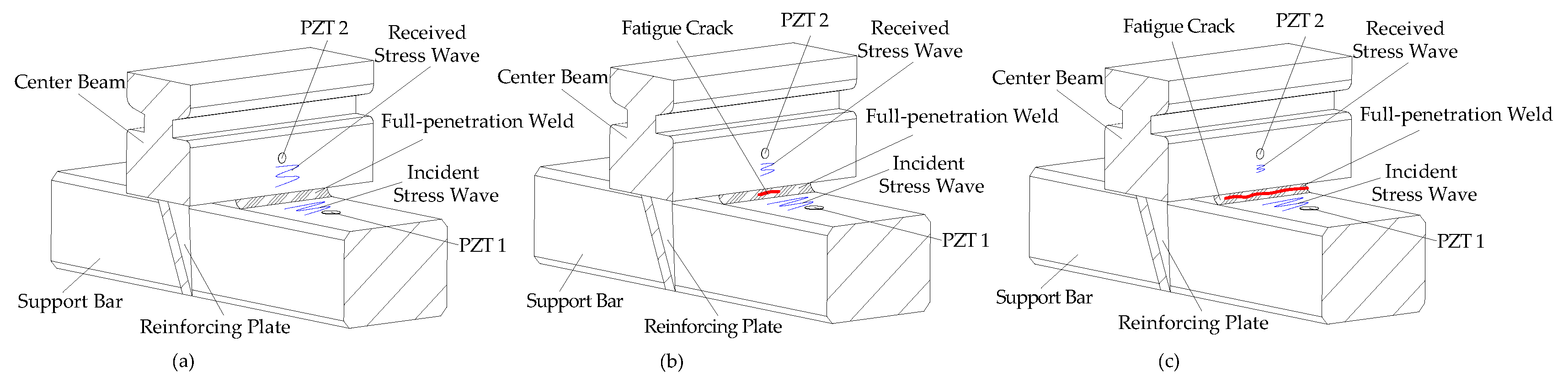
Figure 3.
The photo of the full-scale CB/SB assembly of the MBEJ.

Figure 4.
The details of the test specimen (unit: mm). (a) Top view. (b) I-I section left view.

Figure 5.
Photo of the experimental setup.

Figure 6.
Loading configuration of the test specimen (unit: mm). (a) Three-dimensional view. (b) Left view. (c) Front view.
Figure 6.
Loading configuration of the test specimen (unit: mm). (a) Three-dimensional view. (b) Left view. (c) Front view.

Figure 7.
Partial enlargement photos of typical weld defect before the fatigue test. (a) South side of the CB/SB1 joint. (b) North side of the CB/SB1 joint. (c) South side of the CB/SB2 joint. (d) North side of the CB/SB2 joint. (e) South side of the CB/SB3 joint. (f) North side of the CB/SB3 joint. (g) South side of the CB/SB4 joint. (h) North side of the CB/SB4 joint.


Figure 8.
Diagram of fatigue cracks of south side of the CB/SB3 joint. (a) 3.2 million cycles. (b) 4.0 million cycles.
Figure 8.
Diagram of fatigue cracks of south side of the CB/SB3 joint. (a) 3.2 million cycles. (b) 4.0 million cycles.

Figure 9.
Effect of fatigue cycles on static load—displacement curves. (a) Measurement point DI1. (b) Measurement point DI7. (c) Measurement point DI4. (d) Measurement point DI3. (e) Measurement point DI5.
Figure 9.
Effect of fatigue cycles on static load—displacement curves. (a) Measurement point DI1. (b) Measurement point DI7. (c) Measurement point DI4. (d) Measurement point DI3. (e) Measurement point DI5.

Figure 10.
Time domain signals of PZT6 sensor for monitoring south side weld of CB/SB2 joint.

Figure 11.
Time domain signals of PZT8 sensor for monitoring north side weld of CB/SB2 joint.

Figure 12.
Mechanical analysis of CB/SB joint under the test load. (a) Details of the CB/SB joint. (b) Mechanical model of support bar. (c) Bending moment diagram of the support bar.
Figure 12.
Mechanical analysis of CB/SB joint under the test load. (a) Details of the CB/SB joint. (b) Mechanical model of support bar. (c) Bending moment diagram of the support bar.

Figure 13.
Wavelet packet energy analysis results of the specimen during the fatigue test. (a) The south side of CB/SB1 joint. (b) The south side of CB/SB2 joint. (c) The north side of CB/SB2 joint. (d) The south side of CB/SB3 joint. (e) The north side of CB/SB3 joint. (f) The south side of CB/SB4 joint. (g) The north side of CB/SB4 joint.


Table 1.
Material properties of the test specimen.
| Young’s Modulus (GPa) | Shear Modulus (GPa) | Yield Stress (MPa) | Ultimate Stress (MPa) | Density (kg·m3) | Poisson Ratio |
|---|---|---|---|---|---|
| 200 | 76.9 | 350 | 450 | 7850 | 0.3 |
Table 2.
The details of PZT transducers in the test specimen.
| No. | Joint | Weld Side | Actuator | Sensor |
|---|---|---|---|---|
| 1 | CB/SB1 | South | PZT1 | PZT2 |
| 2 | CB/SB1 | North | PZT3 | PZT4 |
| 3 | CB/SB2 | South | PZT5 | PZT6 |
| 4 | CB/SB2 | North | PZT7 | PZT8 |
| 5 | CB/SB3 | South | PZT9 | PZT10 |
| 6 | CB/SB3 | North | PZT11 | PZT12 |
| 7 | CB/SB4 | South | PZT13 | PZT14 |
| 8 | CB/SB4 | North | PZT15 | PZT16 |
Table 3.
The experimental program.
| Static Test | Fatigue Test | ||||||
|---|---|---|---|---|---|---|---|
| Initial Load (kN) | Maximum Load (kN) | Increment of Each Load (kN) | Average Load (kN) | Load Amplitude (kN) | Minimum Load (kN) | Maximum Load (kN) | Frequency (Hz) |
| 0.0 | 120 | 10 | 66 | ±54 | 12 | 120 | 2.5 |
© 2018 by the authors. Licensee MDPI, Basel, Switzerland. This article is an open access article distributed under the terms and conditions of the Creative Commons Attribution (CC BY) license (http://creativecommons.org/licenses/by/4.0/).
Share and Cite
MDPI and ACS Style
Jiang, T.; Zhang, Y.; Wang, L.; Zhang, L.; Song, G. Monitoring Fatigue Damage of Modular Bridge Expansion Joints Using Piezoceramic Transducers. Sensors 2018, 18, 3973. https://doi.org/10.3390/s18113973
AMA Style
Jiang T, Zhang Y, Wang L, Zhang L, Song G. Monitoring Fatigue Damage of Modular Bridge Expansion Joints Using Piezoceramic Transducers. Sensors. 2018; 18(11):3973. https://doi.org/10.3390/s18113973
Chicago/Turabian StyleJiang, Tianyong, Yaowen Zhang, Lei Wang, Liang Zhang, and Gangbing Song. 2018. "Monitoring Fatigue Damage of Modular Bridge Expansion Joints Using Piezoceramic Transducers" Sensors 18, no. 11: 3973. https://doi.org/10.3390/s18113973
Note that from the first issue of 2016, this journal uses article numbers instead of page numbers. See further details here.