An Enhanced LoRaWAN Security Protocol for Privacy Preservation in IoT with a Case Study on a Smart Factory-Enabled Parking System


Abstract
:
1. Introduction
2. Background
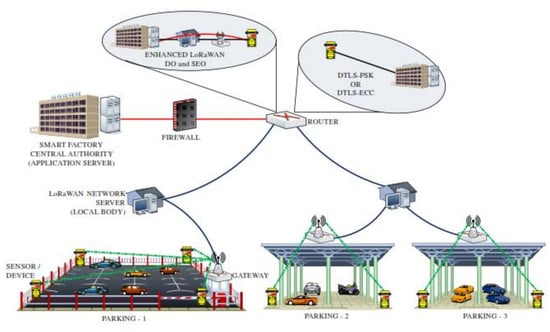
2.1. LoRaWAN Network Architecture
2.2. Standard LoRaWAN Protocol
2.2.1. Over-the-Air Activation and Activation by Personalization
2.2.2. Join Procedure
2.3. Problems with the Standard LoRaWAN Protocol
- There is no prevention against the replay attack in the Join_Request and Join_Accept messages because the device and the network server cannot accept the freshness of AppNonce and DevNonce, respectively.
- The end-to-end security between the device and the application server is broken because AppSKey is known to the network server.
- The session keys are derived from the long-term secret key AppKey. Therefore, if AppKey is compromised, the past session keys can be recovered while the encrypted traffic can be decrypted, i.e., the perfect forward secrecy does not hold.
3. Related Work
4. Enhanced LoRaWAN Security Protocol
4.1. Default Option
- (1)
- A device attempts to enter the LoRaWAN network by sending the Join_Request message. To protect this message, the device generates the i-th fresh nonce and the message integrity code . Figure 4 shows how the is computed in the way of making the Join_Request message fresh, which enables this step to prevent replay attacks. In addition, is obtained by computing (AppKey, Join_Request).
- (2)–(3)
- On receiving the Join_Request message, the network server verifies if the received and are correct. In the positive case, the device is successfully authenticated to the network server, which then prepares for the network server’s i-th nonce by eXclusive-ORing a randomly generated nonce with the received , generates two session keys and and computes . Note that can guarantee the device the Join_Accept message’s freshness and relation to the received Join_Request message. Finally, the network server encrypts with all the message contents including , , , , , and into the Join_Accept message, which is then sent to the device. At the same time, the network server forwards the application server the newly-generated session key so that the App_Auth_Req message can be safely exchanged with that key. Upon a receipt of the Join_Accept message, the device decrypts it with and verifies the correctness of the decrypted and . If the verification is successful, the device can conclude that the message is fresh and the network server is authentic, followed by computing the two session keys, and . At this point, it is worth noting that this protocol provides the first two messages’ freshness, the mutual authentication between the device and the network server and the session key exchange.
- (4)
- Once having successfully verified the Join_Accept message, the device proceeds with the remaining Steps (4)–(6) by preparing for the App_Auth_Req message. For this message, it first computes , which is made fresh by being derived from . In addition, its ECDH private key d is randomly generated, and the corresponding public key is computed where G is the base point. Finally, the session key is applied to compute (AppSKey, App_Auth_Req), which secures both the App_Auth_Req message and the ECDH key exchange.
- (5)
- Upon receiving the App_Auth_Req message, the application server validates and . If valid, it randomly creates its own ECDH private key a and calculates the corresponding public key , followed by obtaining . At this point, the application server can defend against resource exhaustion attacks by flooding the App_Auth_Req messages because it first checks prior to the expensive ECDH operations. Afterwards, it makes and (AppSKey, App_Auth_Res), which, together with other values, constitute the App_Auth_Res message. Note that , which is a digital signature generated with the application server’s private key , plays a role in defending against the man-in-the-middle attacks launched by a malicious network server. The application server finishes Step (5) by responding to the device with the App_Auth_Res message.
- (6)
- After receiving the App_Auth_Res message, the device first verifies the received and . If they are valid, the device trusts that the received message is fresh and protected by . Such a trust allows the device to establish the session key without being vulnerable to the replay and resource exhaustion attacks. Then, the device validates with the application’s public key . If is correct, the application server is authenticated to the device, which then concludes the proposed protocol by sending the App_Auth_Ack message. At this point, the device can prevent the man-in-the-middle attacks by a malicious network server because can only be generated by the application server. Once the message arrives, the application server attempts to verify if it is fresh and valid with the received and . If this verification is successful, the device is authenticated to the application server, as well as shown to have .
4.2. Security-Enhanced Option
5. Security Analysis
5.1. BAN Analysis
5.1.1. Default Option


- (G1) and (G2) are satisfied by (D4) and (D8), respectively.
- (G3)–(G6) are satisfied by (D12), (D13), (D9) and (D10), respectively.
- (G7) and (G8) are satisfied by (D29) and (D34), respectively.
- (G9)–(G16) are satisfied by (D23), (D24), (D27), (D28), (D18), (D19), (D32) and (D33), respectively.
5.1.2. Security-Enhanced Option


5.1.3. Security Properties
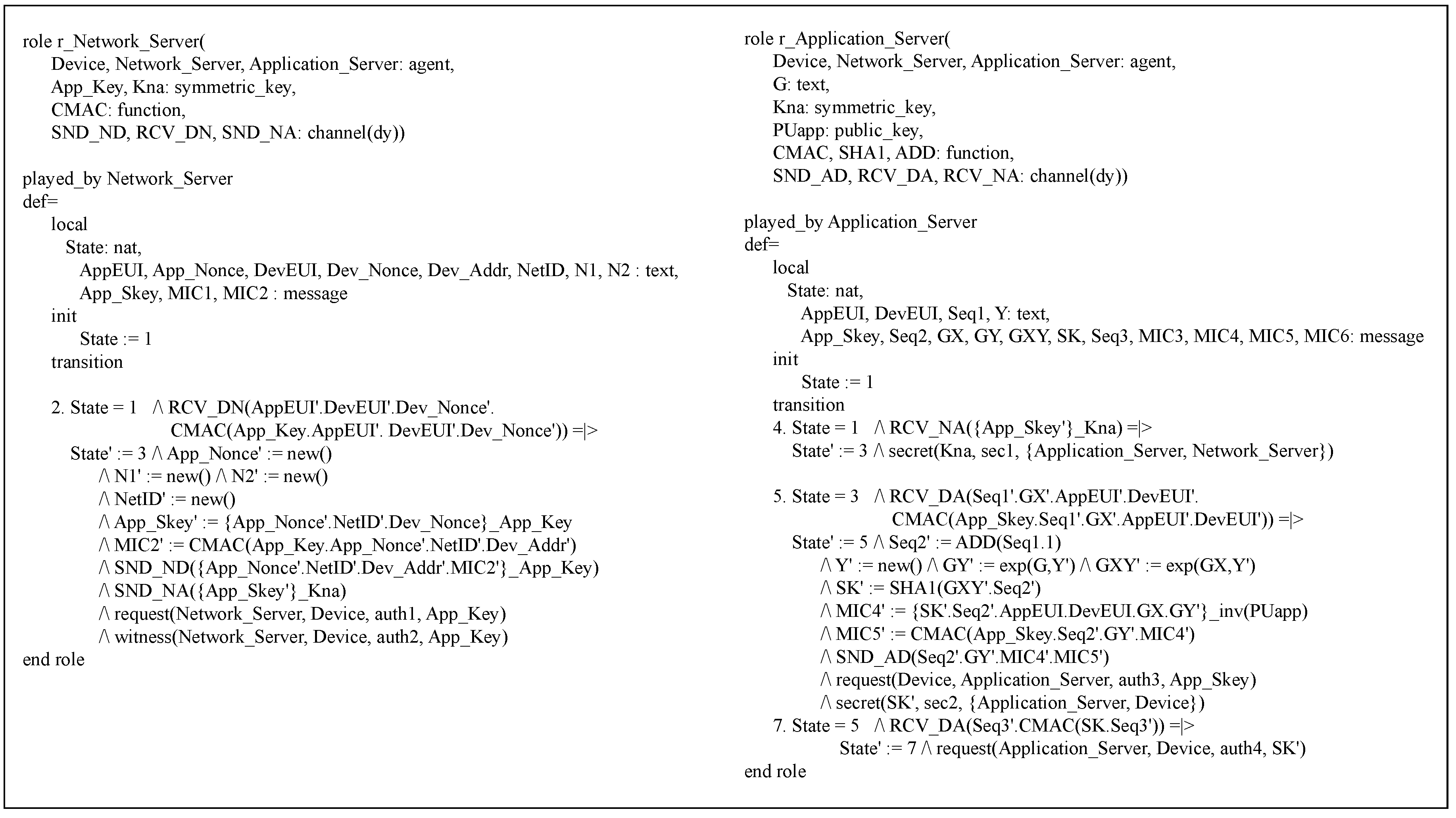
5.2. AVISPA Analysis
5.2.1. Default Option
5.2.2. Security Enhanced Option
6. Performance Evaluation
6.1. Evaluation of the Proposed Protocol over a Low-Power Device
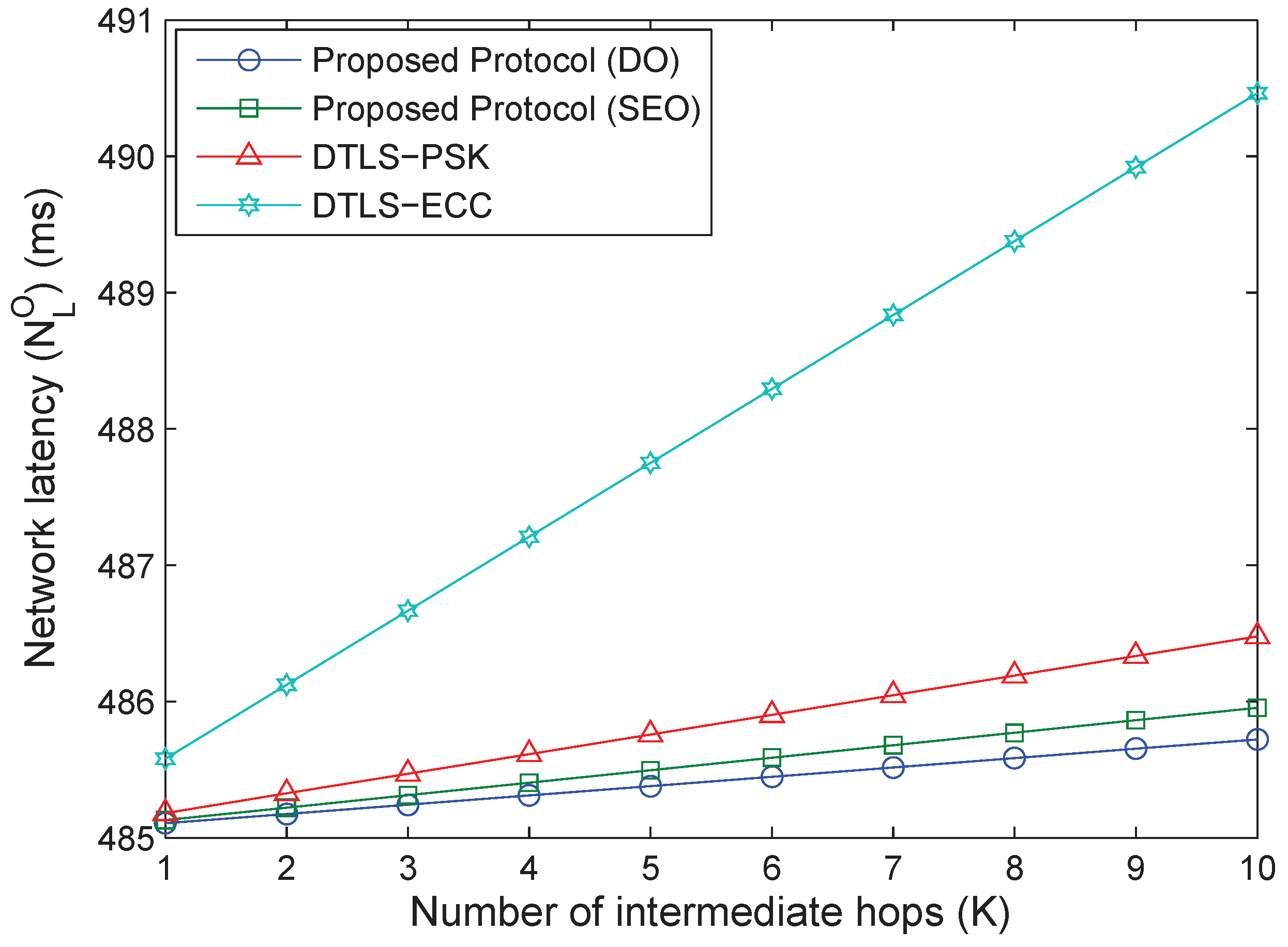
6.2. Smart Factory-Enabled Parking System with the Proposed Protocol
6.3. Applicability to the New LoRaWAN Specification v1.1
7. Conclusions and Future Remarks
Author Contributions
Funding
Conflicts of Interest
References
- Hakiri, A.; Berthou, P.; Gokhale, A.; Abdellatif, S. Publish/subscribe-enabled software defined networking for efficient and scalable IoT communications. IEEE Commun. Mag. 2015, 53, 48–54. [Google Scholar] [CrossRef] [Green Version]
- Saxena, N.; Roy, A.; Sahu, B.J.R.; Kim, H. Efficient IoT Gateway over 5G Wireless: A New Design with Prototype and Implementation Results. IEEE Commun. Mag. 2017, 55, 97–105. [Google Scholar] [CrossRef]
- Sharma, V.; Kumar, R.; Kaur, R. UAV-assisted content-based sensor search in IoTs. Electron. Lett. 2017, 53, 724–726. [Google Scholar] [CrossRef]
- Jayaraman, P.P.; Yavari, A.; Georgakopoulos, D.; Morshed, A.; Zaslavsky, A. Internet of things platform for smart farming: Experiences and lessons learnt. Sensors 2016, 16, 1884. [Google Scholar] [CrossRef] [PubMed]
- Minoli, D.; Sohraby, K.; Occhiogrosso, B. IoT Considerations, Requirements, and Architectures for Smart Buildings x2014; Energy Optimization and Next-Generation Building Management Systems. IEEE Internet Things J. 2017, 4, 269–283. [Google Scholar]
- Zhang, X.; Zhang, J.; Li, L.; Zhang, Y.; Yang, G. Monitoring citrus soil moisture and nutrients using an iot based system. Sensors 2017, 17, 447. [Google Scholar] [CrossRef] [PubMed]
- Sun, X.; Ansari, N. Traffic Load Balancing among Brokers at the IoT Application Layer. IEEE Trans. Netw. Serv. Manag. 2017. [Google Scholar] [CrossRef]
- Pratama, A.Y.N.; Zainudin, A.; Yuliana, M. Implementation of IoT-based passengers monitoring for smart school application. In Proceedings of the 2017 International Electronics Symposium on Engineering Technology and Applications (IES-ETA), Surabaya, Indonesia, 26–27 September 2017; pp. 33–38. [Google Scholar]
- Li, G.; Zhou, H.; Li, G.; Feng, B. Application-aware and Dynamic Security Function Chaining for Mobile Networks. J. Internet Serv. Inf. Secur. 2017, 7, 21–34. [Google Scholar]
- Sharma, V.; You, I.; Leu, F.; Atiquzzaman, M. Secure and efficient protocol for fast handover in 5G mobile Xhaul networks. J. Netw. Comput. Appl. 2018, 102, 38–57. [Google Scholar] [CrossRef]
- Banerjee, D.; Dong, B.; Taghizadeh, M.; Biswas, S. Privacy-Preserving Channel Access for Internet of Things. IEEE Internet Things J. 2014, 1, 430–445. [Google Scholar] [CrossRef]
- Baiardi, F.; Tonelli, F.; Isoni, L. Application Vulnerabilities in Risk Assessment and Management. J. Wirel. Mob. Netw. Ubiquitous Comput. Dependable Appl. 2016, 7, 41–59. [Google Scholar]
- Wei, Z.; Zhao, B. A Space Information Service Forwarding Mechnism Based on Software Defined Network. J. Internet Serv. Inf. Secur. 2017, 7, 48–60. [Google Scholar]
- Verma, S.; Kawamoto, Y.; Fadlullah, Z.M.; Nishiyama, H.; Kato, N. A Survey on Network Methodologies for Real-Time Analytics of Massive IoT Data and Open Research Issues. IEEE Commun. Surv. Tutor. 2017, 19, 1457–1477. [Google Scholar] [CrossRef]
- Balid, W.; Refai, H.H. On the development of self-powered iot sensor for real-time traffic monitoring in smart cities. In Proceedings of the 2017 IEEE SENSORS, Glasgow, UK, 29 October–1 November 2017; pp. 1–3. [Google Scholar]
- Fortino, G.; Russo, W.; Savaglio, C.; Shen, W.; Zhou, M. Agent-Oriented Cooperative Smart Objects: From IoT System Design to Implementation. IEEE Trans. Syst. Man Cybern. Syst. 2017, PP, 1–18. [Google Scholar] [CrossRef]
- Sharma, V.; You, I.; Kumar, R. Resource-based mobility management for video users in 5G using catalytic computing. Comput. Commun. 2007. [Google Scholar] [CrossRef]
- Parada, R.; Melia-Segui, J. Gesture Detection Using Passive RFID Tags to Enable People-Centric IoT Applications. IEEE Commun. Mag. 2017, 55, 56–61. [Google Scholar] [CrossRef] [Green Version]
- Li, C.; Peng, Z.; Huang, T.Y.; Fan, T.; Wang, F.K.; Horng, T.S.; Muñoz-Ferreras, J.M.; Gómez-García, R.; Ran, L.; Lin, J. A review on recent progress of portable short-range noncontact microwave radar systems. IEEE Trans. Microwave Theory Tech. 2017, 65, 1692–1706. [Google Scholar] [CrossRef]
- Kong, L.; Khan, M.K.; Wu, F.; Chen, G.; Zeng, P. Millimeter-wave wireless communications for IoT-cloud supported autonomous vehicles: Overview, design, and challenges. IEEE Commun. Mag. 2017, 55, 62–68. [Google Scholar] [CrossRef]
- Singh, R.; Singh, E.; Nalwa, H.S. Inkjet printed nanomaterial based flexible radio frequency identification (RFID) tag sensors for the internet of nano things. RSC Adv. 2017, 7, 48597–48630. [Google Scholar] [CrossRef] [Green Version]
- Wu, X.; Li, F. A multi-domain trust management model for supporting RFID applications of IoT. PLoS ONE 2017, 12, e0181124. [Google Scholar] [CrossRef] [PubMed]
- Petäjäjärvi, J.; Mikhaylov, K.; Hämäläinen, M.; Iinatti, J. Evaluation of LoRa LPWAN technology for remote health and wellbeing monitoring. In Proceedings of the 2016 10th International Symposium on Medical Information and Communication Technology (ISMICT), Worcester, MA, USA, 20–23 March 2016; pp. 1–5. [Google Scholar]
- Bardyn, J.P.; Melly, T.; Seller, O.; Sornin, N. IoT: The era of LPWAN is starting now. In Proceedings of the 2016: 42nd European Solid-State Circuits Conference, Lausanne, Switzerland, 12–15 September 2016; pp. 25–30. [Google Scholar]
- Garcia-Carrillo, D.; Marin-Lopez, R.; Kandasamy, A.; Pelov, A. A CoAP-Based Network Access Authentication Service for Low-Power Wide Area Networks: LO-CoAP-EAP. Sensors 2017, 17, 2646. [Google Scholar] [CrossRef] [PubMed]
- Sanchez-Iborra, R.; Gamez, J.S.; Santa, J.; Fernandez, P.J.; Skarmeta, A.F. Integrating LP-WAN Communications within the Vehicular Ecosystem. J. Internet Serv. Inf. Secur. 2017, 7, 45–56. [Google Scholar]
- Sánchez, B.B.; Alcarria, R.; de Rivera, D.S.; Sánchez-Picot, Á. Enhancing Process Control in Industry 4.0 Scenarios using Cyber-Physical Systems. JoWUA 2016, 7, 41–64. [Google Scholar]
- Desnitsky, V.; Levshun, D.; Chechulin, A.; Kotenko, I.V. Design Technique for Secure Embedded Devices: Application for Creation of Integrated Cyber-Physical Security System. JoWUA 2016, 7, 60–80. [Google Scholar]
- Carniani, E.; Costantino, G.; Marino, F.; Martinelli, F.; Mori, P. Enhancing Video Surveillance with Usage Control and Privacy-Preserving Solutions. JoWUA 2016, 7, 20–40. [Google Scholar]
- Li, J.; Li, J.; Chen, X.; Jia, C.; Lou, W. Identity-based encryption with outsourced revocation in cloud computing. IEEE Trans. Comput. 2015, 64, 425–437. [Google Scholar] [CrossRef]
- Li, P.; Li, J.; Huang, Z.; Li, T.; Gao, C.Z.; Yiu, S.M.; Chen, K. Multi-key privacy-preserving deep learning in cloud computing. Future Gener. Comput. Syst. 2017, 74, 76–85. [Google Scholar] [CrossRef]
- Li, P.; Li, J.; Huang, Z.; Gao, C.Z.; Chen, W.B.; Chen, K. Privacy-preserving outsourced classification in cloud computing. Clust. Comput. 2017. [Google Scholar] [CrossRef]
- Li, J.; Zhang, Y.; Chen, X.; Xiang, Y. Secure attribute-based data sharing for resource-limited users in cloud computing. Comput. Secur. 2018, 72, 1–12. [Google Scholar] [CrossRef]
- Huang, Z.; Liu, S.; Mao, X.; Chen, K.; Li, J. Insight of the Protection for Data Security under Selective Opening Attacks. Inf. Sci. 2017. [Google Scholar] [CrossRef]
- Bankov, D.; Khorov, E.; Lyakhov, A. Mathematical model of LoRaWAN channel access. In Proceedings of the 2017 IEEE 18th International Symposium on a World of Wireless, Mobile and Multimedia Networks (WoWMoM), Macau, China, 12–15 June 2017; pp. 1–3. [Google Scholar]
- Lanza, J.; Sánchez, L.; Muñoz, L.; Galache, J.A.; Sotres, P.; Santana, J.R.; Gutiérrez, V. Large-Scale Mobile Sensing Enabled Internet-of-Things Testbed for Smart City Services. Int. J. Distrib. Sens. Netw. 2015, 11. [Google Scholar] [CrossRef]
- Park, S.; Park, S.; Byun, J.; Park, S. Design of a mass-customization-based cost-effective Internet of Things sensor system in smart building spaces. Int. J. Distrib. Sens. Netw. 2016, 12. [Google Scholar] [CrossRef] [Green Version]
- Adelantado, F.; Vilajosana, X.; Tuset-Peiro, P.; Martinez, B.; Melia-Segui, J.; Watteyne, T. Understanding the limits of LoRaWAN. IEEE Commun. Mag. 2017, 55, 34–40. [Google Scholar] [CrossRef]
- Zulian, S. Security Threat Analysis and Countermeasures for LoRaWAN Join Procedure. 2016. Available online: https://labs.mwrinfosecurity.com/publications/lo/ (accessed on 26 December 2017).
- Miller, R. LoRa Security: Building a Secure LoRa Solution. 23 March 2016. Available online: https://labs.mwrinfosecurity.com/publications/lo/ (accessed on 26 December 2017).
- Na, S.; Hwang, D.; Shin, W.S.; Kim, K.H. Scenario and Countermeasure for Replay Attack Using Join Request Messages in LoRaWAN. In Proceedings of the 2017 International Conference on Information Networking (ICOIN), Da Ning, Vietnam, 11–13 January 2017. [Google Scholar]
- Kim, J.; Song, J. A Dual Key-Based Activation Scheme for Secure LoRaWAN. Hindawi Wirel. Commun. Mob. Comput. 2017, 2017, 6590713. [Google Scholar] [CrossRef]
- Garcia, D.; Marin, R.; Kandasamy, A.; Pelov, A. LoRaWAN Authentication in Diameter Draft-Garcia-Dime-Diameter-Lorawan-00. 30 May 2016. Available online: https://tools.ietf.org/html/draft-garcia-dime-diameter-lorawan-00 (accessed on 26 December 2017).
- Garcia, D.; Marin, R.; Kandasamy, A.; Pelov, A. LoRaWAN Authentication in RADIUS Draft-Garcia-Radext-Radius-Lorawan-03. 2 May 2017. Available online: https://www.ietf.org/archive/id/draft-garcia-radext-radius-lorawan-03.txt (accessed on 26 December 2017).
- Fossati, T.; Tschofenig, H. Transport Layer Security (TLS)/Datagram Transport Layer Security (DTLS) Profiles for the Internet of Things. IETF RFC 7925. 2016. Available online: https://tools.ietf.org/html/rfc7925 (accessed on 1 May 2018).
- Burrows, M.; Abadi, M.; Needham, R. A logic of authentication. ACM Trans. Comput. Syst. 1990, 8, 18–36. [Google Scholar] [CrossRef]
- Viganò, L. Automated Security Protocol Analysis with the AVISPA Tool. Electron. Notes Theor. Comput. Sci. 2006, 155, 61–86. [Google Scholar] [CrossRef]
- Koulamas, C.; Giannoulis, S.; Fournaris, A. IoT Components for Secure Smart Building Environments. In Components and Services for IoT Platforms; Springer: New York, NY, USA, 2017; pp. 335–353. [Google Scholar]
- Farrell, S. LPWAN Overview: Draft-ietf-lpwan-overview-01. Available online: https://tools.ietf.org/html/draft-ietf-lpwan-overview-01 (accessed on 1 May 2018).
- Casals, L.; Mir, B.; Vidal, R.; Gomez, C. Modeling the Energy Performance of LoRaWAN. Sensors 2017, 17, 2364. [Google Scholar] [CrossRef] [PubMed]
- Sornin, N.M.; Luis, T.E.T.K.; Hersent, O. LoRaWAN Specification V1.0.2. Available online: https://lora-alliance.org/resource-hub/lorawantm-specification-v102 (accessed on 1 May 2018).
- Girard, P. Low Power Wide Area Networks Security. 9 December 2015. Available online: https://docbox.etsi.org/Workshop/2015/201512_M2MWORKSHOP/S04_WirelessTechnoforIoTandSecurityChallenges/GEMALTO_GIRARD.pdf (accessed on 26 December 2017).
- Avoine, G.; Ferreira, L. Rescuing LoRaWAN 1.0. 2017. Available online: https://fc18.ifca.ai/preproceedings/13.pdf (accessed on 15 May 2018).
- Miller, V.S. Use of Elliptic Curves in Cryptography. In Advances in Cryptology—CRYPTO’85 Proceedings; Springer: Berlin/Heidelberg, Germany, 1985; Volume 218, pp. 417–426. [Google Scholar]
- Johnson, D.; Menezes, A.; Vanstone, S. The Elliptic Curve Digital Signature Algorithm (ECDSA). Int. J. Inf. Secur. 2001, 1, 26–63. [Google Scholar] [CrossRef]
- You, I.; Hori, Y.; Sakurai, K. Enhancing SVO Logic for Mobile IPv6 Security Protocols. J. Wirel. Mob. Netw. Ubiquitous Comput. Dependable Appl. 2011, 2, 26–52. [Google Scholar]
- Shin, D.; Sharma, V.; Kim, J.; Kwon, S.; You, I. Secure and Efficient Protocol for Route Optimization in PMIPv6-Based Smart Home IoT Networks. IEEE Access 2017, 5, 11100–11117. [Google Scholar] [CrossRef]
- Menezes, A.J.; van Oorschot, P.C.; Vanstone, S.A. Handbook of Applied Cryptography; CRC Press: Boca Raton, FL, USA, 1996. [Google Scholar]
- Chevalier, Y.; Compagna, L.; Cuellar, J.; Drielsma, P.; Mantovani, J.; Mödersheim, S.; Vigneron, L. A High Level Protocol Specification Language for Industrial Security-Sensitive Protocols. In Proceedings of the Workshop on Specification and Automated Processing of Security Requirements, Linz, Austria, 20–24 September 2004. [Google Scholar]
- Basin, D.; Mödersheim, S.; Viganò, L. OFMC: A symbolic model checker for security protocols. Electron. Notes Theor. Comput. Sci. 2005, 4, 61–86. [Google Scholar] [CrossRef]
- Alferes, J.J.; Leite, J. SATMC: A SAT-Based Model Checker for Security Protocols. In European Workshop on Logics in Artificial Intelligence—JELIA 2004: Logics in Artificial Intelligence; Springer: Berlin/Heidelberg, Germany; Lisbon, Portugal, 2004; Volume 3229, pp. 730–733. [Google Scholar]
- Turuani, M. SATMC: A SAT-Based Model Checker for Security Protocols. In International Conference on Rewriting Techniques and Applications—RTA 2006: Term Rewriting and Applications; Springer: Berlin/Heidelberg, Germany; Seattle, WA, USA, 2006; Volume 4098, pp. 277–286. [Google Scholar]
- Boichut, Y.; Heam, P.C.; Kouchnarenko, O.; Oehl, F. Improvements on the Genet and Klay Technique to Automatically Verify Security Protocols. In Proceedings of the ETAPS 2004 Workshop on Automated Verification of Infinite States Systems (AVIS 2004), Barcelona, Spain, 3–4 April 2004; pp. 1–11. [Google Scholar]
- Guan, J.; Sharma, V.; You, I.; Atiquzzaman, M. Extension of MIH to Support FPMIPv6 for Optimized Heterogeneous Handover. arXiv, 2017; arXiv:1705.09835. [Google Scholar]
- Lee, J.H.; Bonnin, J.M.; Seite, P.; Chan, H.A. Distributed IP mobility management from the perspective of the IETF: Motivations, requirements, approaches, comparison, and challenges. IEEE Wirel. Commun. 2013, 20, 159–168. [Google Scholar] [CrossRef]


| Symbol | Description |
|---|---|
| Join_request | Join request to attach the end device to the LoRa network |
| Application identifier | |
| Device identifier | |
| Nonce value randomly generated by the device | |
| The i-th nonce value computed by the device | |
| AES 128 cipher-based MAC function with the secret key K and the message M | |
| Message integrity code | |
| The i-th message integrity code except for the digital signatures and | |
| Network session key | |
| Application session key | |
| The long-term key shard between a device and a network server | |
| Nonce value randomly generated by the network server | |
| The i-th nonce value computed by the network server | |
| Network identifier | |
| End device address | |
| Delay between RX and TX | |
| Optional list for channel frequencies | |
| SHA 1 hash function, which takes an input M and produces a 160-bit | |
| App_Auth_Req | Application authentication request message |
| App_Auth_Res | Application authentication response message |
| The i-th sequence number | |
| The session key between a device and its application server | |
| Concatenation operation | |
| App_Auth_Ack | Application authentication acknowledgment message |
| Private key of the application server | |
| Public key of the application server | |
| a and | Device’s elliptic curve Diffie–Hellman private and public keys |
| b and | Application server’s elliptic curve Diffie–Hellman private and public keys |
| G | Elliptic curve Diffie–Hellman base point |
| Function adding zero octets to make the length of the data a multiple of 16 | |
| hval refers to hash value and [.] to the index. |
| Standard LoRaWAN [51] | Na et al. [41] | Kim and Song [42] | Garcia et al. [43] | Garcia et al. [44] | Proposed | |
|---|---|---|---|---|---|---|
| Scheme | Standard | XoR | Dual | Diameter | Radius | DO-SEO |
| Mutual Authentication | YES | YES | YES | YES | YES | YES |
| Secure Key Exchange | YES | YES | YES | YES | YES | YES |
| Perfect Forward Secrecy | NO | NO | NO | NO | NO | YES |
| End-to-End Security | NO | NO | NO | NO | NO | YES |
| Defense against a Replay Attack | NO | YES | NO | NO | NO | YES |
| Statement | Meaning |
|---|---|
| P believes X and acts as if X were true. | |
| P receives X at present or in the past time. | |
| P once said X, which means that X was sent to P at some point. | |
| P has jurisdiction over X. | |
| X is fresh. | |
| X is encrypted with a secret K. | |
| It means that X is combined with secret K. MIC can be expressed by this notation. | |
| K is a secret key only known to P and Q. | |
| K is P’s public key. | |
| K is a secret only known to P and Q. |
| Environment | Specific |
|---|---|
| CPU | Intel® Core™i5-6300HQ 2.30 GHz (0.88 GHz) |
| RAM | 8GB |
| Compiler | gcc (GCC) 6.4.0 |
| OS | Windows 10 64bit (Cygwin32) |
| DTLS Library | TinyDTLS 0.8.2 |
| Cipher Suite | TLS_ECDHE_ECDSA_WITH_AES_128_CCM_8 |
| Cipher Suite | TLS_PSK_WITH_AES_128_CCM_8 |
| Message | Size (Bytes) | Overhead (ms) |
|---|---|---|
| Client_Hello(1) | 42 | 1 |
| Hello_Verify_Request | 19 | - |
| Client Hello(2) | 58 | 1 |
| Server_Hello | 38 | - |
| Server_Hello_Done | 0 | - |
| Client_Key_Exchange | 17 | 1 |
| Finished(Client) | 12 | 1 |
| Finished(Server)_Verify | 12 | 1 |
| Total Overhead | 5 |
| Message | Size (Bytes) |
|---|---|
| Client_Hello(1) | 42 |
| Hello_Verify_Request | 19 |
| Client_Hello(2) | 58 |
| Server_Hello, Server Hello Done | 38 |
| Client_Key_Exchange, Finished | 29 |
| Finished | 12 |
| Total Message Size | 198 |
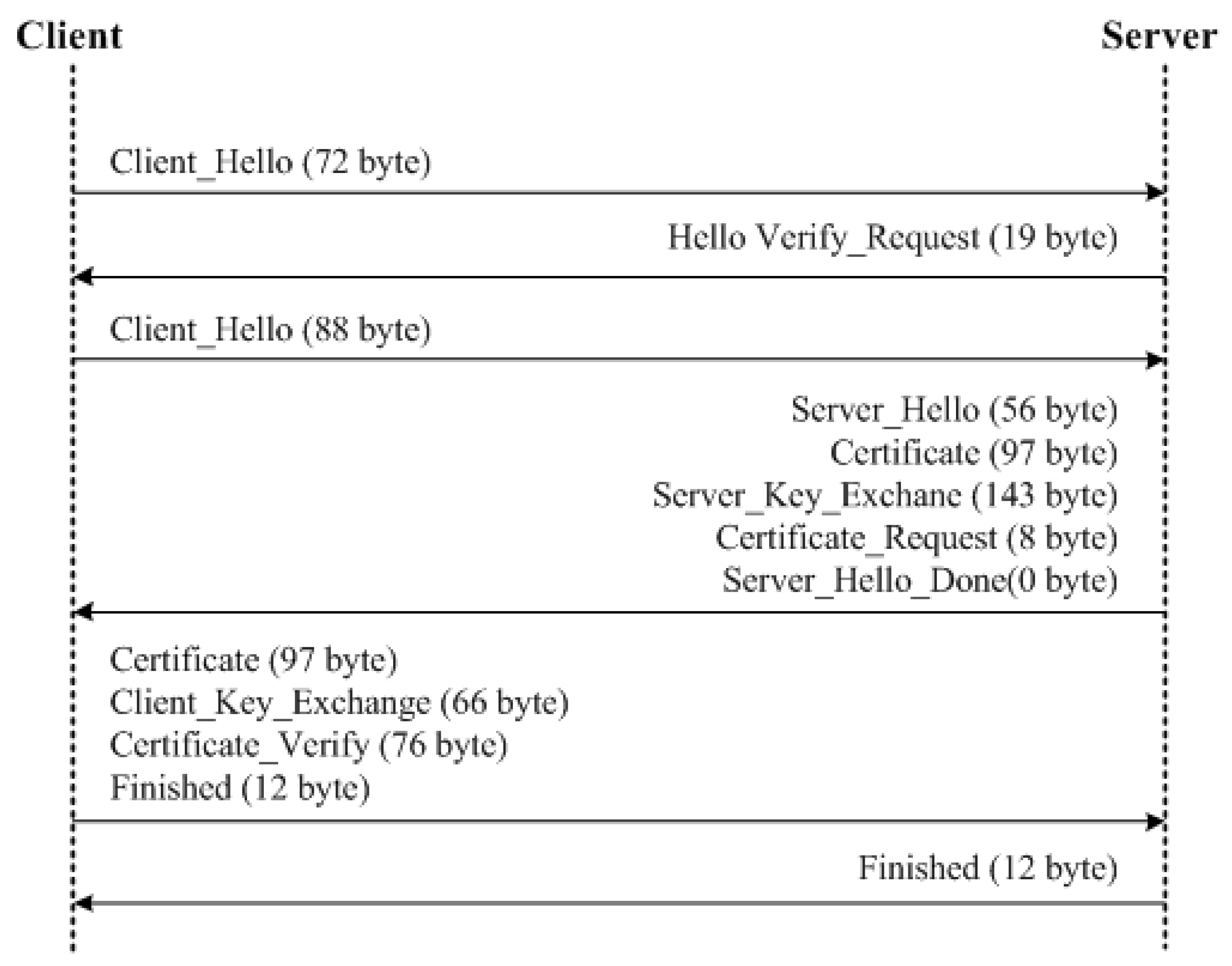
| Message | Size (Bytes) | Overhead (ms) |
|---|---|---|
| Client_Hello(1) | 72 | 1 |
| Hello_Verify_Request | 19 | - |
| Client Hello(2) | 88 | 1 |
| Server_Hello | 56 | - |
| Certificate | 97 | 1 |
| Server_Key_Exchange | 143 | - |
| Certificate_Request | 8 | - |
| Server_Hello_Done | 0 | - |
| Client_Key_Exchange | 66 | 31 |
| Certificate_Verify | 76 | 31 |
| Finished(Client) | 12 | 31 |
| Finished(Server) | 12 | 1 (for verification) |
| Total Overhead | 97 |
| Message | Size (Bytes) |
|---|---|
| Client_Hello(1) | 72 |
| Hello_Verify_Request | 19 |
| Client_Hello(2) | 88 |
| Server_Hello, Certificate, Server_Key_Exchange, Certificate_Request, Server_Hello_Done | 304 |
| Certificate, Client_Key_Exchange, Certificate_Verify, Finished | 251 |
| Finished | 12 |
| Total Message Size | 746 |
| Environment | Specific |
|---|---|
| CPU | Intel® Core™i5-6300HQ 2.30 GHz (0.88 GHz) |
| RAM | 8 GB |
| Compiler | Visual Studio 2017 32 bit |
| OS | Windows 10 64 bit |
| Message | Size (Bytes) | Overhead (ms) |
|---|---|---|
| App_Auth_Req | 37 | 1 |
| APP_Auth_Res | 53 | 9 |
| App_Auth_ACK | 4 | 1 |
| Total Overhead | 11 | |
| Total Message Size | 94 |
| Message | Size (Bytes) | Overhead (ms) |
|---|---|---|
| App_Auth_Req | 69 | 3 |
| APP_Auth_Res | 53 | 12 |
| App_Auth_ACK | 4 | 1 |
| Total Overhead | 16 | |
| Total Message Size | 126 |
| Protocol | Overhead (ms) | Overhead Impact w.r.t. DO | Overhead Impact w.r.t. SEO | Message Size (Bytes) | Message Size Impact w.r.t. DO | Message Size Impact w.r.t. SEO |
|---|---|---|---|---|---|---|
| DO | 11 | - | −31.25% | 94 | - | −25.39% |
| SEO | 16 | +31.25% | - | 126 | +25.39% | - |
| DTLS-PSK | 5 | −54.54% | −68.75% | 198 | +52.52% | +36.36% |
| DTLS-ECC | 97 | +88.65% | +83.50% | 746 | +87.39% | +83.10% |
| Environment | Specific |
|---|---|
| Device Type | Mobile |
| Make | Lenovo |
| Chipset | Mediatek MT6753 |
| CPU | Octa-core 1.3 GHz Cortex-A53 |
| GPU | Mali-T720MP3 |
| Compiler | Visual Studio 2017 (Android Kit) |
| OS | Android 5.1.1 |
| Message | DO (min) (ms) | DO (max) (ms) | SEO (min) (ms) | SEO (max) (ms) |
|---|---|---|---|---|
| App_Auth_Req | 12 | 12 | 20 | 20 |
| APP_Auth_Res | 5 | 9 | 5 | 12 |
| App_Auth_ACK | 1 | 1 | 1 | 1 |
| Total Overhead | 18 | 22 | 26 | 33 |
| Parameter | Value |
|---|---|
| 10 | |
| 11 Mbps | |
| 20 ms | |
| 64 Bytes | |
| 45.35 ms | |
| 10–50 ms | |
| 1–10 | |
| 100 ms | |
| 20 ms |
© 2018 by the authors. Licensee MDPI, Basel, Switzerland. This article is an open access article distributed under the terms and conditions of the Creative Commons Attribution (CC BY) license (http://creativecommons.org/licenses/by/4.0/).
Share and Cite
You, I.; Kwon, S.; Choudhary, G.; Sharma, V.; Seo, J.T. An Enhanced LoRaWAN Security Protocol for Privacy Preservation in IoT with a Case Study on a Smart Factory-Enabled Parking System. Sensors 2018, 18, 1888. https://doi.org/10.3390/s18061888
You I, Kwon S, Choudhary G, Sharma V, Seo JT. An Enhanced LoRaWAN Security Protocol for Privacy Preservation in IoT with a Case Study on a Smart Factory-Enabled Parking System. Sensors. 2018; 18(6):1888. https://doi.org/10.3390/s18061888
Chicago/Turabian StyleYou, Ilsun, Soonhyun Kwon, Gaurav Choudhary, Vishal Sharma, and Jung Taek Seo. 2018. "An Enhanced LoRaWAN Security Protocol for Privacy Preservation in IoT with a Case Study on a Smart Factory-Enabled Parking System" Sensors 18, no. 6: 1888. https://doi.org/10.3390/s18061888