Practical Latency Analysis of a Bluetooth 5 Decentralized IoT Opportunistic Edge Computing System for Low-Cost SBCs
Abstract
1. Introduction
- First, in order to establish the basics, it reviews the state of the art on OEC systems.
- Second, it details the design and implementation of a novel OEC system based on Bluetooth 5 and on the use of Single-Board Computers (SBCs). Such a system is decentralized (there is not a single central controller), distributed (storage is distributed among all the nodes that make up the network), scalable (the OEC system can grow by adding more nodes without affecting the service) and modular (the system is able to adapt to support different communication technologies). Moreover, the system architecture supports providing services such as Resource Sharing (to improve processing speed), Data Routing (to find the path that should take the data from one IoT node to another) or Node Discovery (to find IoT nodes easily). None of the previous characteristics have been found together in a single development described in current literature.
- Third, it analyzes the feasibility of the proposed OEC system through performance tests that estimate the system latency in end-to-end communications, when using a different location of the bootstrap node, for different IoT hardware and when enabling/disabling communications security mechanisms. As a result, this article provides useful guidelines for the developers of future OEC systems.
- Finally, all the source code used for running the experiments presented in this article is available online, thus allowing any researcher or developer to use, to adapt and to extend the developed OEC system.
2. State of the Art
2.1. Opportunistic Edge Computing Systems
- No or intermittent Internet connectivity due to poor wireless coverage or to certain communications restrictions (e.g., due to their expected battery life).
- Limited local storage and computing power.
- Reduced mobility, which prevents IoT/IIoT nodes from communicating with other remote nodes and components of the IoT/IIoT architecture.
- Reliability: it is the capacity to notify the sender if the delivery of data to recipients was successful or not.
- Packet loss recovery: it is defined as the ability to receive a packet after there are problems during its sending.
- Routed destination: this feature enables routing the transmitted data packets to the intended receiver.
- Forward: it is the ability to send packets to another node if the receiving node is not the end receiver.
- Encryption: it is the process of encrypting data so that it cannot be read by third parties.
2.2. Bluetooth 5 Features for OEC Networks
- The BLE protocol offers a feature for configuring nodes as cache devices in order to act as opportunistic nodes (these are called friend nodes). However, this cache mechanism is not distributed: if a friend node loses connectivity with an IoT node, the cache of this latter node is lost.
- The BLE protocol is part of the Bluetooth 4.x set of standards, so none of the different modulations provided by Bluetooth 5 version are officially supported, thus impeding the use of the long-range mode, which are useful for many OEC systems.
- The friend node feature of BLE is replaced by a P2P implementation of the cache storage.
- To compensate the lack of support for long-range communications, the BLE Mesh protocol was modified to operate using Bluetooth 5 modulations. However, it is important to consider that the Long Range modulation is not applicable to any OEC application, since it achieves a greater propagation distance at the cost of increasing its time on air, which implies a higher energy consumption and the saturation of the wireless media.
2.3. Conclusions on the Analysis of the State of the Art
- The use of mobile Fog Computing allows for providing Edge Computing functionality, thus decreasing the time response to the IoT nodes through low-cost gateways that can be scattered throughout large environments to provide opportunistic communications.
- The use of a recent communications technology like Bluetooth 5 enables carrying out mobile data exchanges with a longer range and less energy consumption with respect to other technologies such as WiFi, GSM, 4G, or 5G. In addition, the use of Bluetooth 5 does not involve mobility restrictions (like it happens with Ethernet) or transmission restrictions (as it occurs with LoRa, which is limited in terms of transmission speed and packets per time unit).
- As it will be detailed later in Section 3, the proposed architecture has been designed to be jointly decentralized, distributed, scalable and modular. Such features have not been found together in any of the analyzed state-of-the-art systems.
- The devised architecture also includes additional features such as Resource Sharing, Data Routing and Node Discovery, have not been implemented together in the analyzed state-of-the-art systems.
3. Design and Implementation of the Proposed OEC System
3.1. Communications Architecture
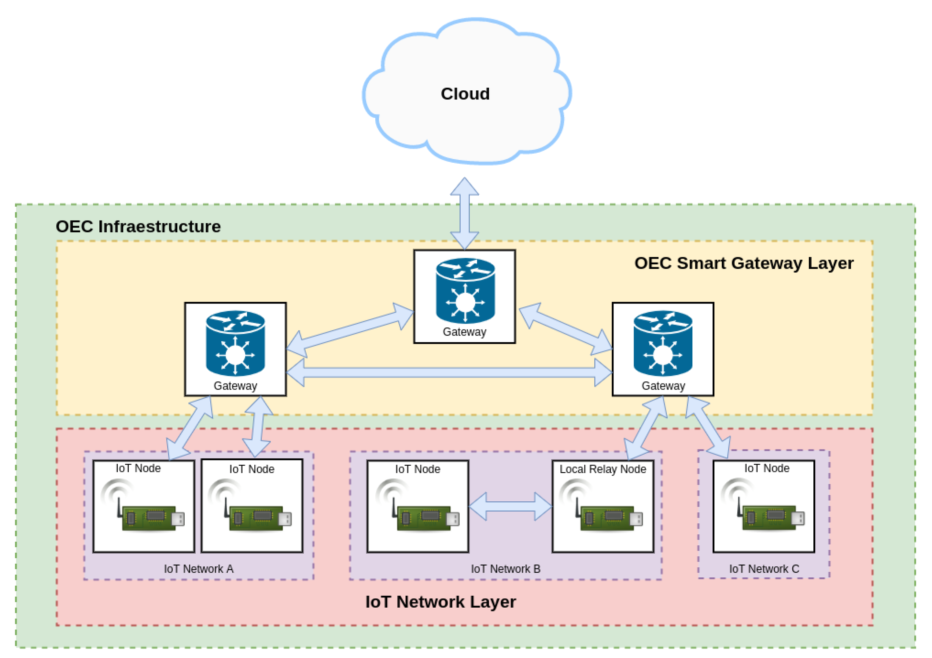
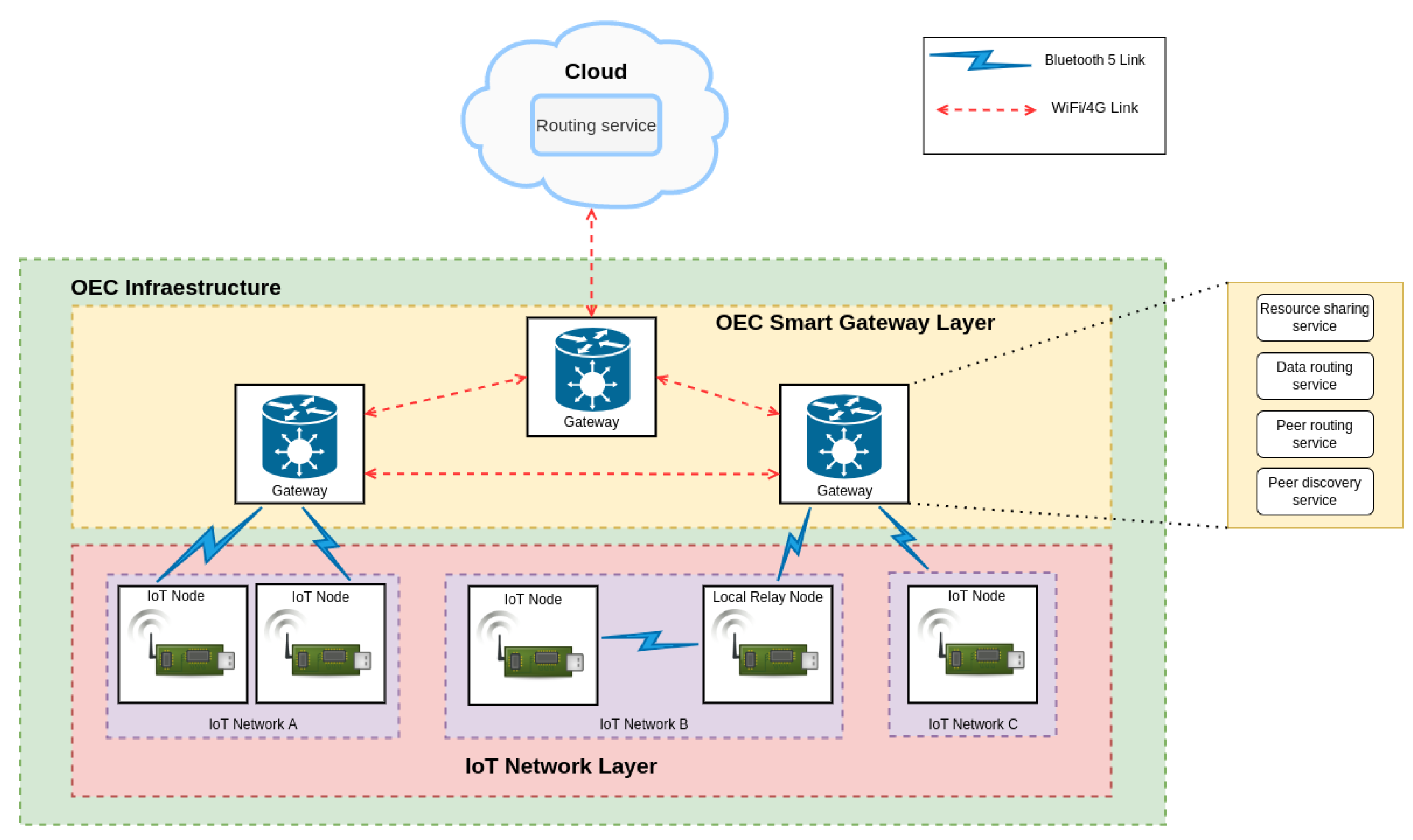
- IoT Network layer. This layer is at the bottom of the architecture and includes the OEC end nodes. As an example, Figure 2 depicts three different IoT networks (A, B and C) that are capable of exchanging data with the upper layer and of sending them to other nodes that belong to the same network (as it is illustrated with the relay node of IoT network B). The IoT OEC devices of this layer make use of sensors to collect information from diverse scattered scenarios and then they send them for processing to the upper layer when it is detected that opportunistic services are available.
- OEC Smart Gateway Layer. This layer consists of OEC gateways that have the ability to provide opportunistic services to the deployed IoT nodes with reduced latency thanks to the proximity to them. Moreover, smart gateways can collaborate among them in order to perform more complex tasks or to exchange data from different IoT networks without making use of the Cloud Layer.
- Cloud layer. This layer is responsible for providing services that cannot be provided by the OEC Smart gateway Layer, like the ones involving heavy processing tasks or large data storage.
3.2. Bluetooth 5-Based Implemented Architecture
3.3. End-to-End Latency Model
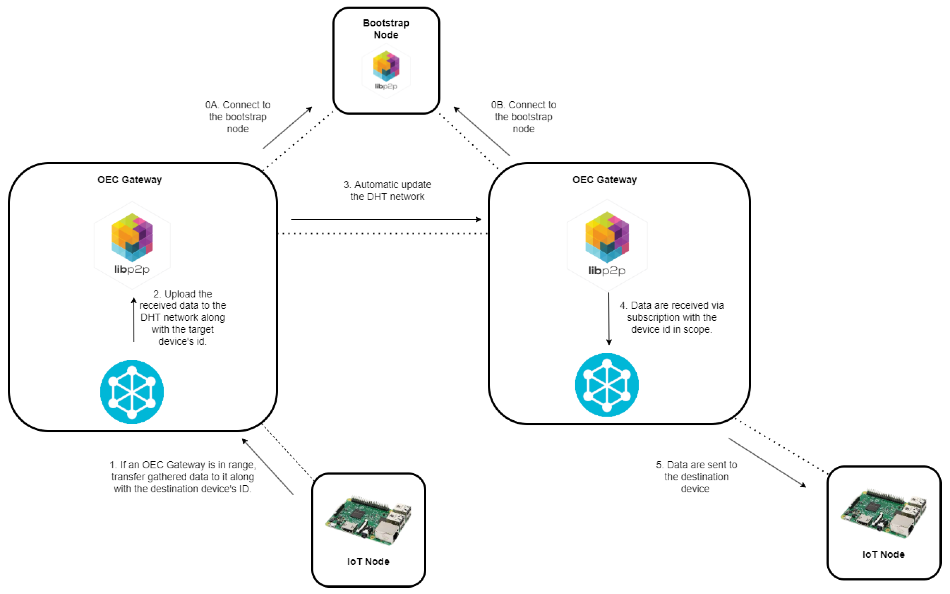
- The data are initially sent from the transmitting node to a smart OEC gateway in the same network via BLE (the required time is which is called ).
- Then, the data are received by an OEC gateway through its serial port (to which a Bluetooth 5 development kit was connected) and posted to the DHT network. The time needed for sharing the data through the DHT networks is what is defined as .
- Finally, the OEC gateway that is located in the same opportunistic network as the IoT destination node, collects the sent data from the DHT network and delivers the message to the IoT node over Bluetooth 5 (using BLE). The time required for performing such operations is called .
3.4. Protocol Stack
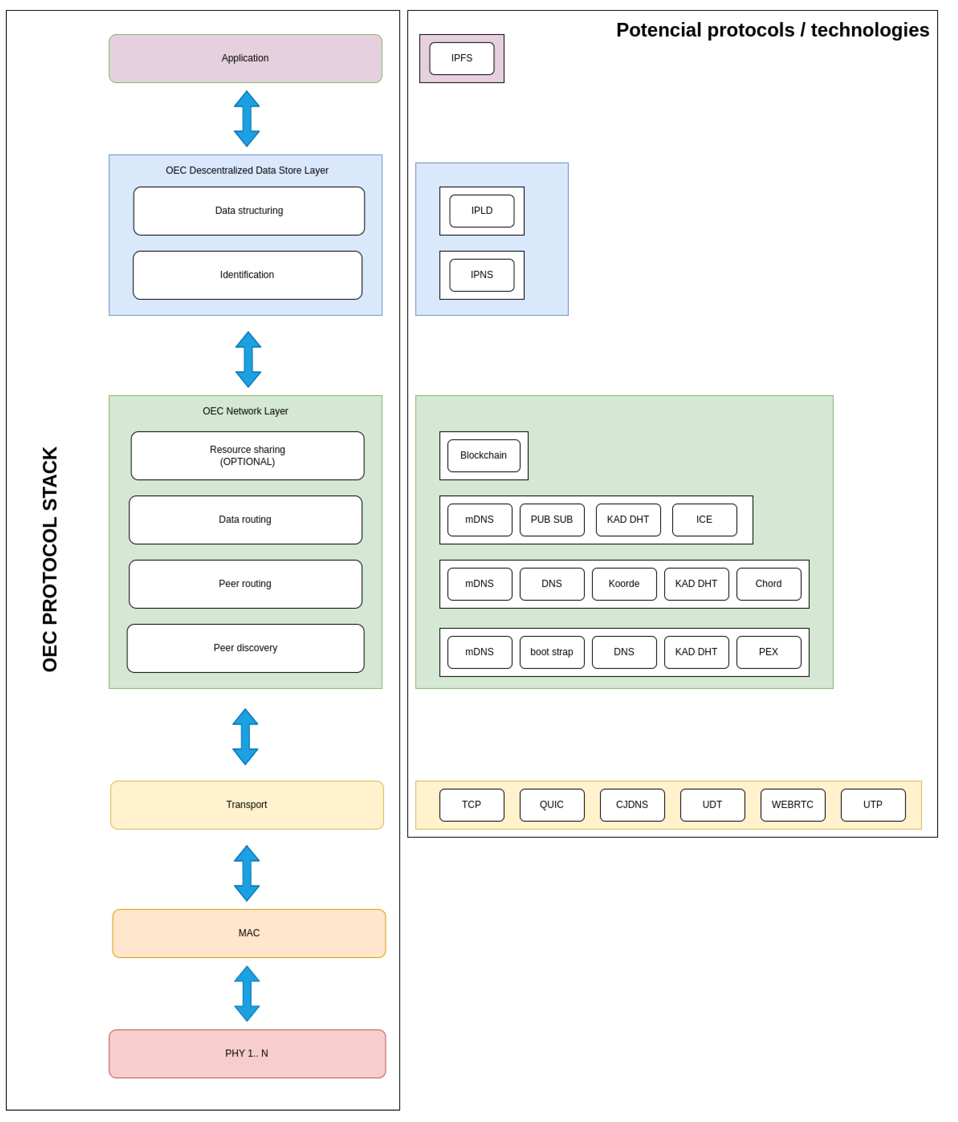
- The Physical (PHY) Layer is responsible for managing the hardware to transmit and receive information via radio waves. For example, in the case of using BLE, data are transmitted using a scheme called Gaussian Frequency-Shift Keying (GFSK).
- The Medium-Access Control (MAC) Layer has the purpose of managing medium access through OEC devices that implement different PHY layers. Thus, this layer is responsible for identifying the communicating nodes within the coverage area, which can be enhanced by using cost-effective algorithms in deployments with mobile and static nodes [28].
- The Transport Layer isolates the upper layers from any changes that may occur in terms of hardware in the lower layers (since PHY and MAC layers are usually implemented directly by specific hardware). There are multiple protocols that can be used to support this layer [29,30], such as TCP (Transport Control Protocol), QUIC (Quick UDP Internet Connections) [31], CJDNS [32], UDT (UDP-based Data Transfer Protocol) [33], WEBRTC (Web Real-Time Communications) [34] and UTP (Micro Transport Protocol) [35].
- The OEC Network Layer provides four services that enable P2P communications:
- -
- Peer discovery and peer routing. When a peer needs to send a message to another peer it first has to know the destination PeerId and its network address. Thus, peer discovery allows for discovering peer addresses thanks to the knowledge provided by the other peers: every contact with a new peer increases the chances of finding the peer that is looked for, while completing the composition of the OEC network, which is reflected in the peer routing tables. The peer routing subsystem exposes an interface to identify the peers to which the message should be routed to. Specifically, the routing subsystem receives a key and returns a list of peers with their information. To perform this task, it is possible to use several technologies, among which Kademlia DHT [36] and multicast DNS (mDNS) [37] are common choices. Nonetheless, other routing mechanisms could be used, such as Domain Name System (DNS) [38], Koorde [39,40] or Chord [41,42]. Similarly, other peer discovery can also be performed through protocols such as DNS, bootstrapping [38] or Peer EXchange (PEX) [43].
- -
- Data routing. Data routing uses mechanisms to forward messages to peers if the receiving peer is not in range of the sending peer (this is really common in opportunistic systems). There are several alternatives to implement data routing in OEC systems, such as mDNS, ICE (Interactive Connectivity Establishment) [44], Publish-Subscribe (PubSub) mechanisms and Kademlia DHT. PubSub and Kademlia DHT are two of the most popular, being the former content-based, while the latter is focused on key-based routing:
- ∗
- PubSub allows for implementing asynchronous messaging systems. In such systems an IoT node can publish content in the messaging system, which is responsible for sending it to the other peers that are subscribed to it. Thus, messages are delivered to groups of interested peers without depending on a centralized infrastructure. Libp2p provides several PubSub P2P implementations (e.g., gossipsub, floodsub, fpisub) that enable real-time application development. Currently, libp2p uses gossipsub by default, which is called so because peers “talk” to each other about the messages they have detected.
- ∗
- In the case of Kademlia DHT, to store a key-value pair, the closest k nodes to the key are located and the pair is sent to them for storage. In addition, each node forwards it to the rest of the nodes, which ensures the persistence of the pair with a very high probability. Pairs expire 24 hours after publication to limit the existence of outdated index information. As is described in [45], in order to find a pair, a node starts by performing a search to find the k nodes with the IDs that are closest to the key. The process stops immediately when any node returns the requested value. For caching purposes, once the lookup is successful, the requesting node stores the pair in the nearest node that did not return the corresponding value.
- -
- Resource sharing. It is actually an advanced service that is optional, since not all OEC devices need to make use of it. There are many ways to share resources among IoT devices (e.g., shared bus memories, databases, file sharing protocols...), but, in terms of decentralization, blockchain is one of the most promising [13], since it provides trustworthy and secure communications among parties that have not meet before [46].
- The OEC Decentralized Data Store Layer is responsible for data structuring and identification, thus providing encryption and authentication.
- Finally, the Application Layer allows IoT devices to access the exchanged data for their processing and thus implement OEC applications.
3.5. Implemented Functionality
- Peer discovery and peer routing. For the implementation presented in this article, among the multiple options mentioned in the previous section, mDNS was ruled out because with such a protocol the nodes are only capable of exchanging data within local networks. This was essentially the reason for selecting Kademlia DHT. Such a protocol is based on the use of Distributed Hash Tables (DHT), which can be used to locate items in decentralized P2P networks. The entries of a Kademlia routing table are called contacts and are organized as an unbalanced routing tree. The leaves of such a tree are lists of k contacts, called k-buckets. Each contact consists of an ID, an IP address and a set of ports. The routing to a specific peer is carried out iteratively: every peer that is on the path toward the destination peer indicates the next hop toward the sending node. This kind of routing is slower than traditional recursive routing strategies, but it is more robust against message losses and simplifies network tracing.
- Data routing. Both PubSub and Kademlia DHT can be used for implementing OEC systems and it is not straightforward to select one over the other, since there are not detailed analyses on the literature that compare their performance (such a study is out of the scope of this article). In the absence of such a performance comparison, for the work presented in this paper, Kademlia DHT was selected, since it is already used for peer discovery, thus simplifying debugging and reducing development complexity.
- Security. Security transports are components of libp2p that encrypt information as it is sent over the network. Thus, such information can only be decrypted by the destination peer. Specifically, TLS is used to provide a secure channel between two peers. In 2020, TLS 1.3 [49] became the default security transport in libp2p. TLS 1.3 provides more privacy than TLS 1.2 in data exchanges by making the handshake more secure. This is due to several changes. One of them is the removal of support for many cipher suites, now supporting only 5 [50]. To start the handshake, the client sends the list of supported cipher suites along with the shared key. The server generates the master key with its shared key along with the client’s and responds with an already encrypted message to the client. Finally, the client verifies the server’s certificate and generates the same master key, since it has the server’s shared key. At this point, the communication between the peers can begin. Although the implementation presented in this article makes use of TLS 1.3, it must be noted that TLS 1.3 is not accessible in browser contexts, so not all libp2p implementations can make it the default security transport. The most popular web browsers include support for TLS 1.3, but there is still no way to attach the necessary identity information to libp2p. Due to these problems, the Noise protocol framework was created [51]. Noise allows for composing widely supported cryptographic primitives, Diffie-Hellman key exchange functions, symmetric ciphers and hash functions, which support the different implementations of libp2p [52].
3.6. OEC Smart Gateway Firmware
- The creation of a libp2p host. Such a host will create a DHT.
- Next, the host connects to the bootstrap node, located in the cloud. Such a node is responsible for providing the initial configuration to the joining nodes so that they can join the opportunistic network.
- The host then performs network discovery and finds all peers that share the same symmetric key. The key (also called rendezvous-point) is a string that is used by the peers to announce their presence.
- Then, the host iterates over the list of available peers and tries to open a connection with each of them. If a direct connection with a specific peer is not possible, the Cloud will be used as a relay, thus acting as an intermediary between the two communicating nodes.
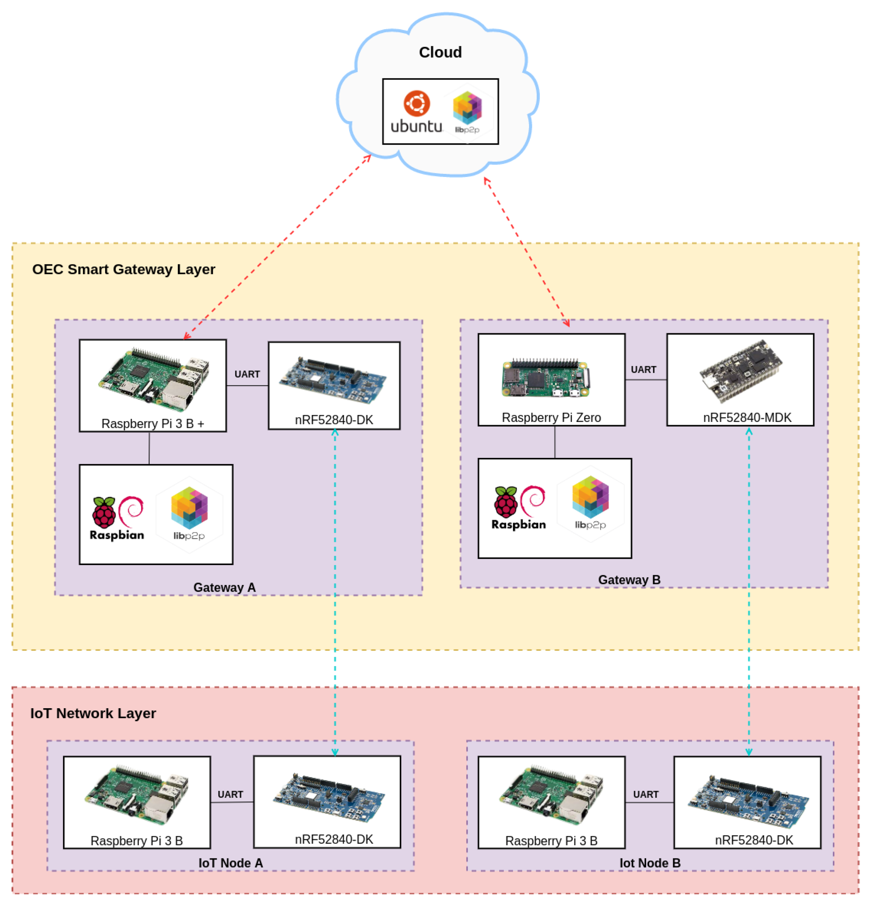
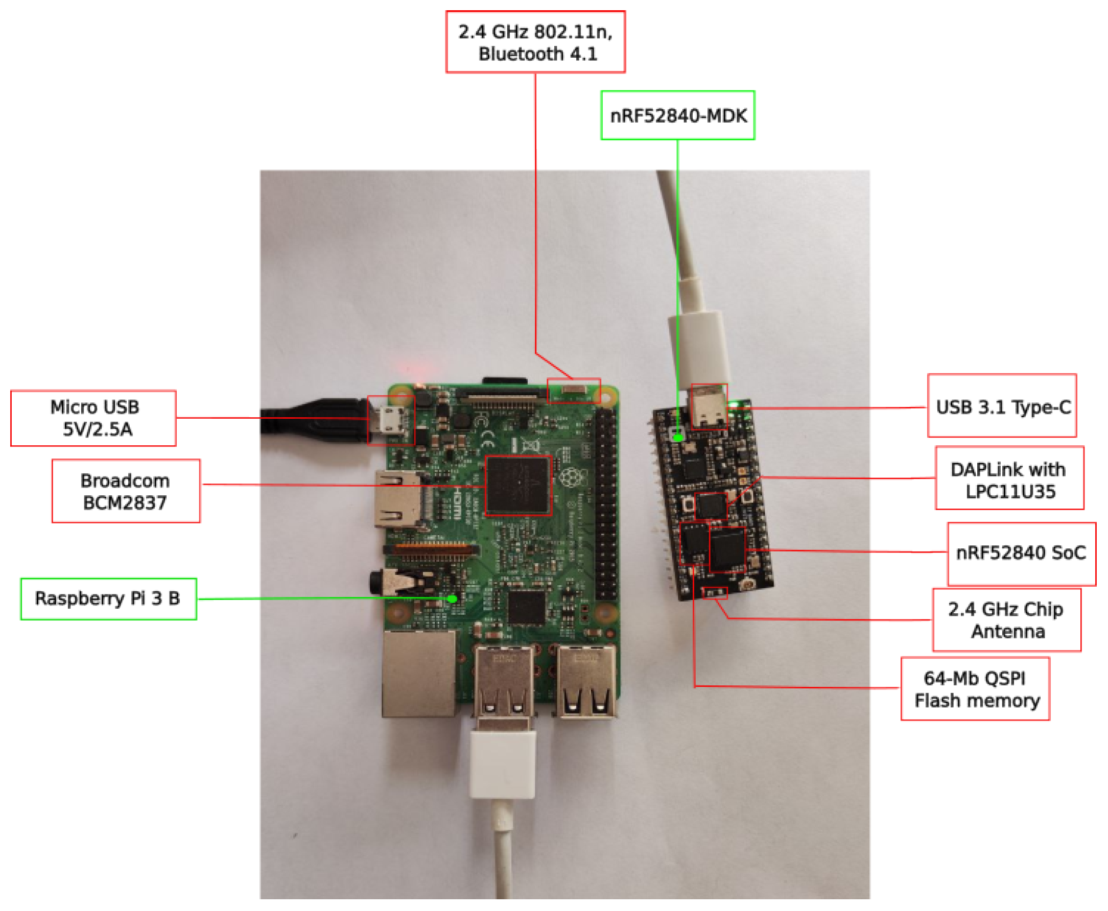
- As it will described later in Section 4.1, the firmware needs to open a connection through the serial port, which will be in charge of receiving the data coming from the IoT communication module through the attached Bluetooth module. These data are stored in the DHT and, therefore, will be accessible to the rest of the peers.
4. Experiments
4.1. Experimental Testbed
4.2. Latency When Running the Bootstrap Node on the Edge and on the Cloud
4.3. IoT OEC Device Performance with Different Hardware
4.4. End-to-End Latency between Nodes in Different Opportunistic Networks
- The data were first sent by using BLE from the sending node to a smart OEC gateway located in the same network.
- Then, the gateway received the data through its serial port (where a Bluetooth 5 development kit was attached to) and uploaded them to the DHT network.
- Next, the OEC gateway that operated in the same opportunistic network where the destination node was located, collected the sent data from the DHT network. To make this communication possible, the role of the Cloud, which acted as a relay, was essential, since it allows for connecting gateways that belong to different IoT networks.
- Finally, the gateway sent the message to the destination node through Bluetooth 5 (using BLE).
4.5. Security Impact on OEC Communications Latency
5. Key Findings
- The performed experiments showed that the obtained latencies allow for performing fast data exchanges, which enable implementing many opportunistic IoT applications. It is difficult to determine how much faster the developed system is in comparison to the systems analyzed in Section 2, since most of them have not performed latency tests. Specifically, among the analyzed works, only the authors of [26] show results related to latency experiments. In such a paper, Bluetooth 5 is included as communications technology, but the obtained latencies are not empirical (they come from simulations) and the simulation scenario differs significantly from the one evaluated in this paper (the scenarios proposed in [26] are related to a remote health monitoring application for rural areas). Considering such differences, the results presented in [26] show latencies between 4 and 17 h to achieve a message delivery rate of a minimum of 38.7%. Therefore, such results are much higher than the end-to-end latencies obtained in this article, which are between 0.93 s and 2.11 s, but for an indoor short-distance scenario.
- As was previously mentioned, since most of the reviewed publications did not include latency results, the measurements obtained with the proposed architecture were compared with those of a simplified edge-cloud architecture. In order to perform the comparison, a system was created with the same architecture as the one proposed in Section 3, but without making use of opportunistic algorithms. Thus, in such an architecture an IoT node sends data through Bluetooth 5 to the nearest non-opportunistic gateway, which establishes a P2P connection (using the Cloud as a relay) with a remote gateway that sends the data to the destination IoT node via Bluetooth 5. It is important to note that, in this non-opportunistic architecture, the destination node needs to be always available for receiving data; otherwise, the sent data are lost because the distributed storage of the receiving IoT node is not available. The results of such a comparison are shown in Figure 30. It can be observed that the latency differences between the two compared architectures are small. Specifically, in the case of the opportunistic architecture, the average measured latency is 736 ms, while the non-opportunistic Cloud-based architecture communications have an average latency of 715 ms. Such a 21 ms time difference essentially corresponds to the contribution of to Equation (2). In any case, the observed time difference is so small that most IoT applications will not be aware of the additional latency, while being able to provide all the benefits of using opportunistic communications.
- It is also possible to compare the cost of deploying the proposed architecture with respect to other state-of-the-art systems. Specifically, Table 5 shows the total cost of the architectures evaluated in Section 2 when compared to the cost of the architecture proposed in this article. For the sake of fairness, the same scenario was assumed for all architectures for estimating the amount of necessary hardware. Such a scenario consisted in a three-story building with 300 floors. Thus, the data of the used hardware were obtained from the experiments described in each article but considering the devised scenario. In Table 5, it can be seen that the overall cost of the proposed system is inexpensive when compared to the architectures described in [7,16,17]. In addition, while the overall cost for the proposed scenario is higher than the one required by the architectures detailed in [9,12], if more floors needed to be covered, the proposed opportunistic architecture would only need to replicate a gateway node (because its range can cover the entire floor), while the other state-of-the-art architectures would need to replicate almost all of their infrastructure on each floor.
- The mathematical terms of the presented latency model (previously described in Section 3.3), can be analyzed by considering the obtained experimental results and the following conclusions can be extracted:
- -
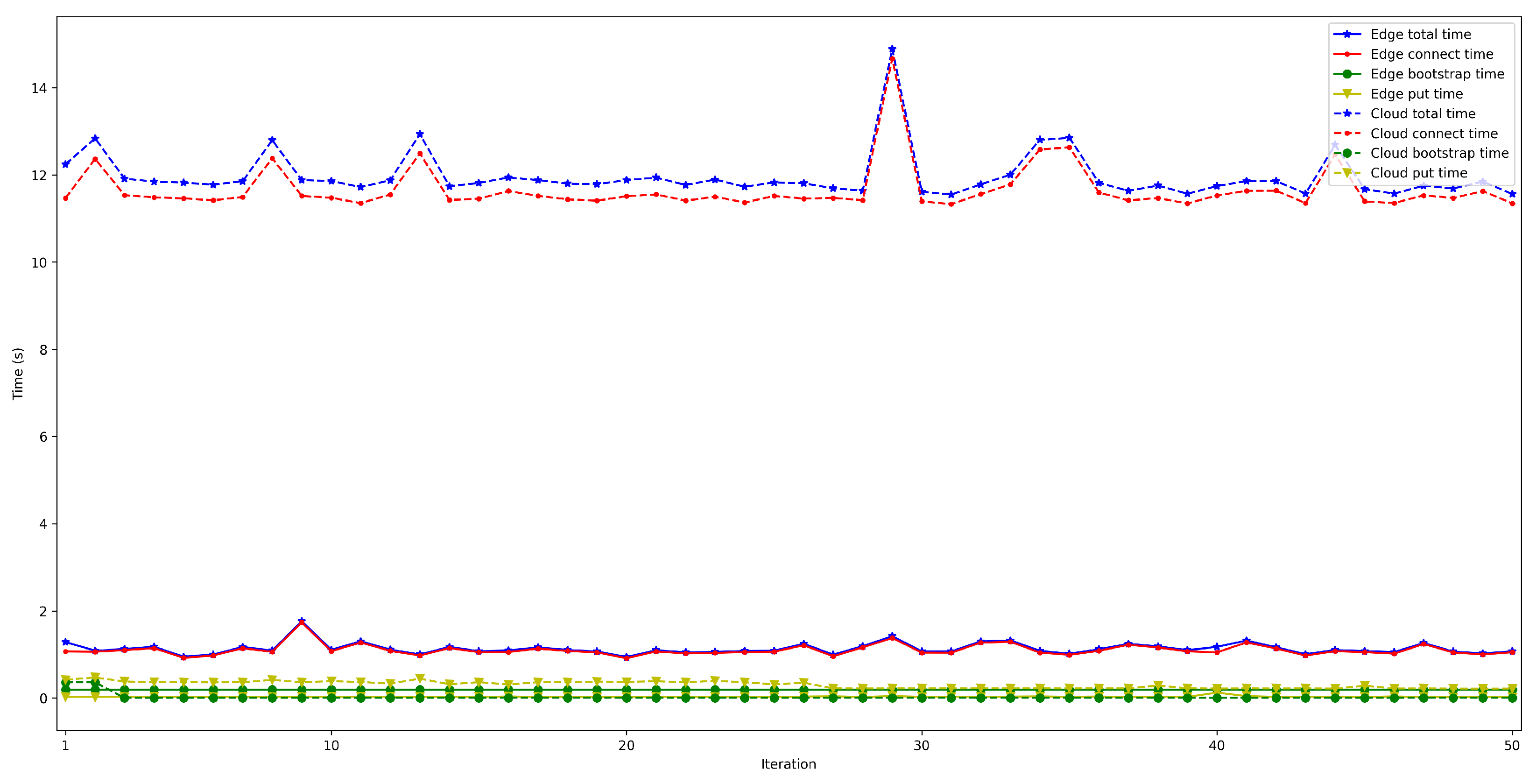
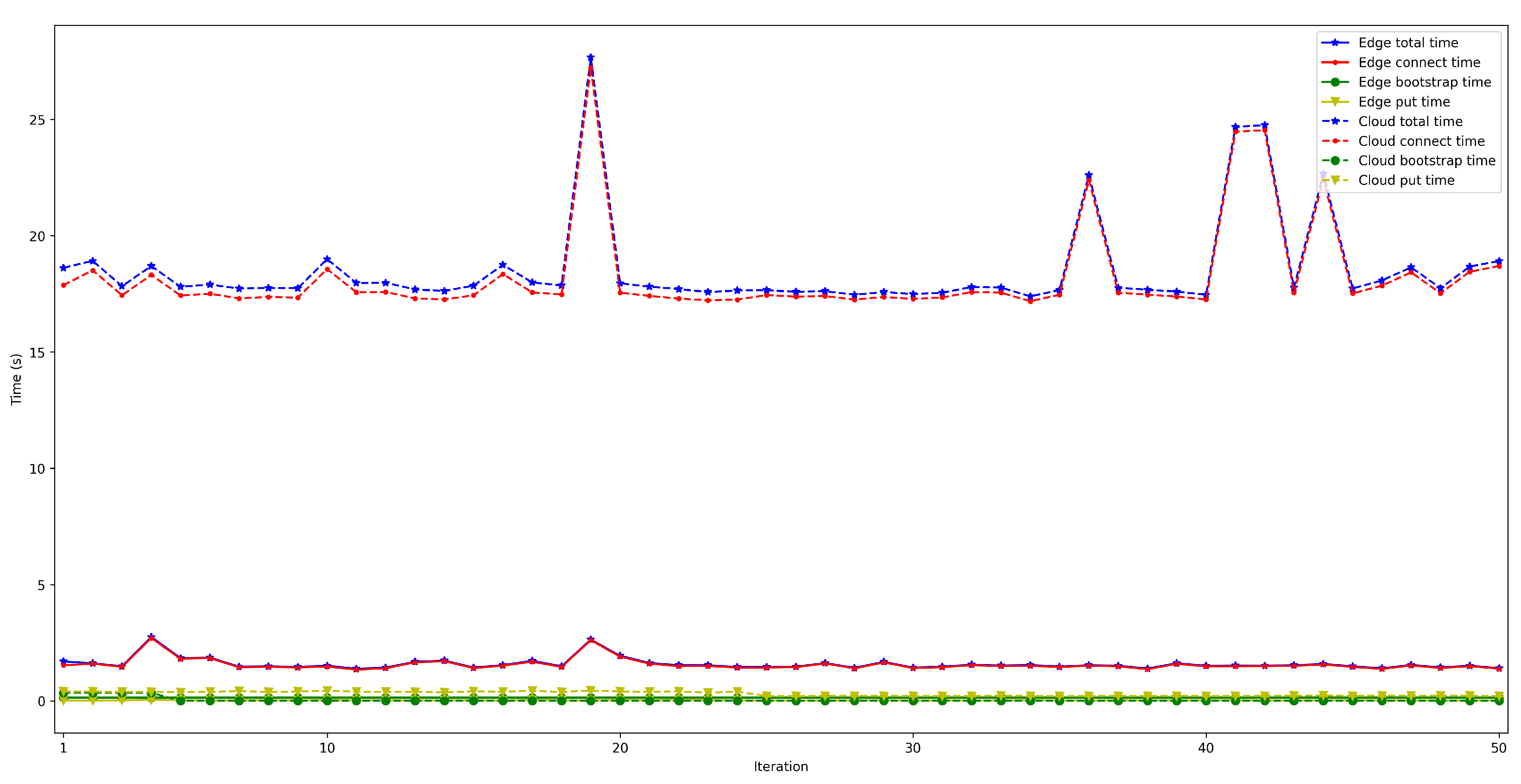
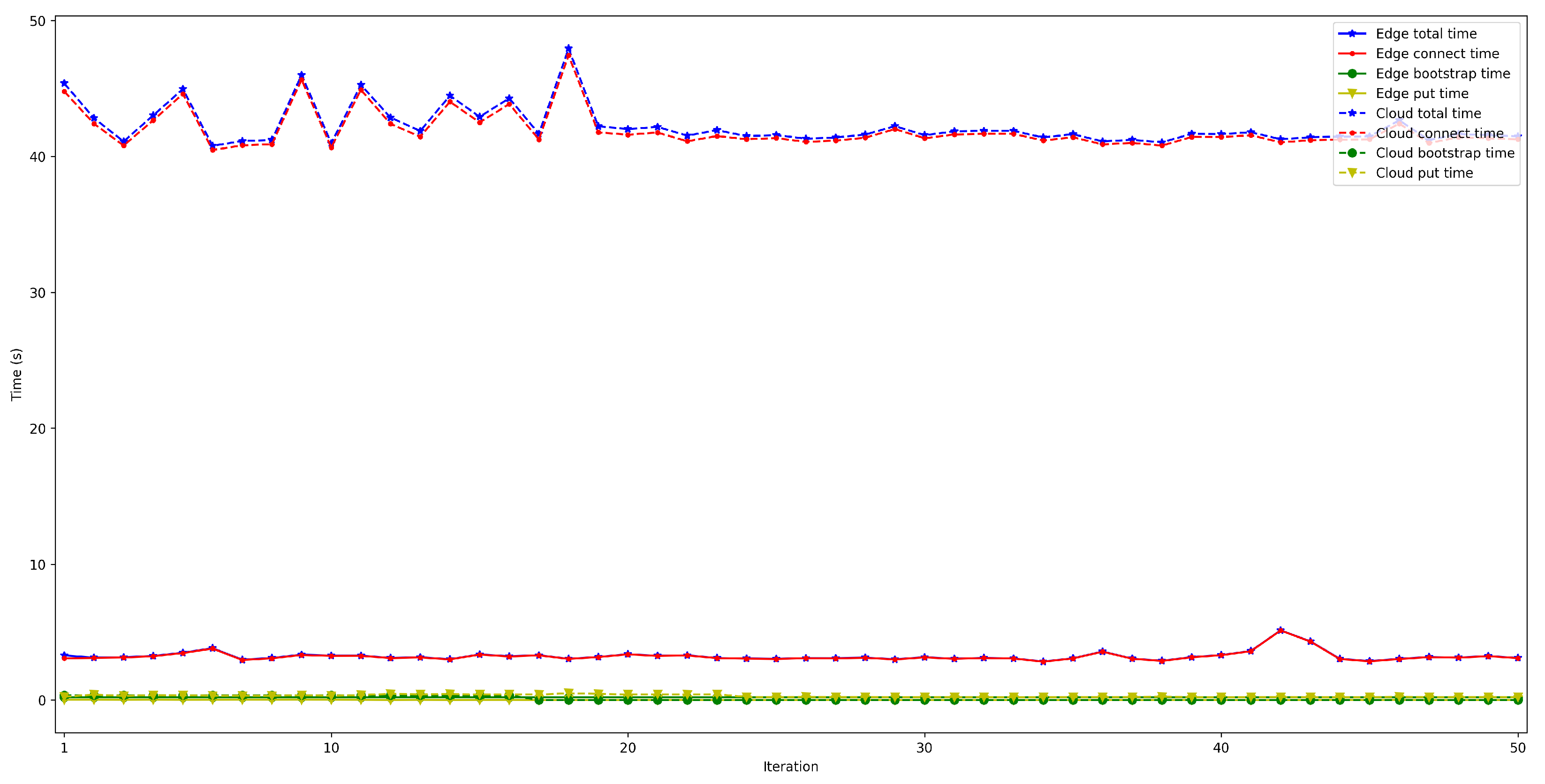
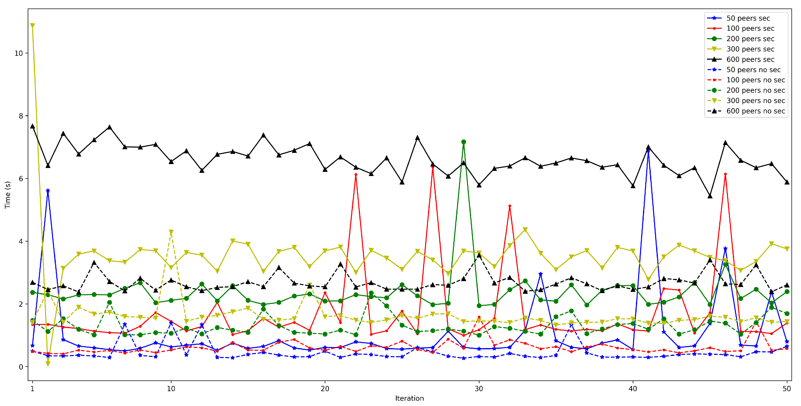
- . In order to measure this latency, tests were carried out in several scenarios and under different network layers (e.g., edge and cloud), different hardware (e.g., Raspberry Pi 3B, Raspberry Pi Zero) and different security configurations. For each test, 50 iterations were made and five situations were measured with 50, 100, 200, 300, and 600 peers connected to the network. The performed experiments showed a constant latency of roughly 50 ms, independently of the scenario.
- -
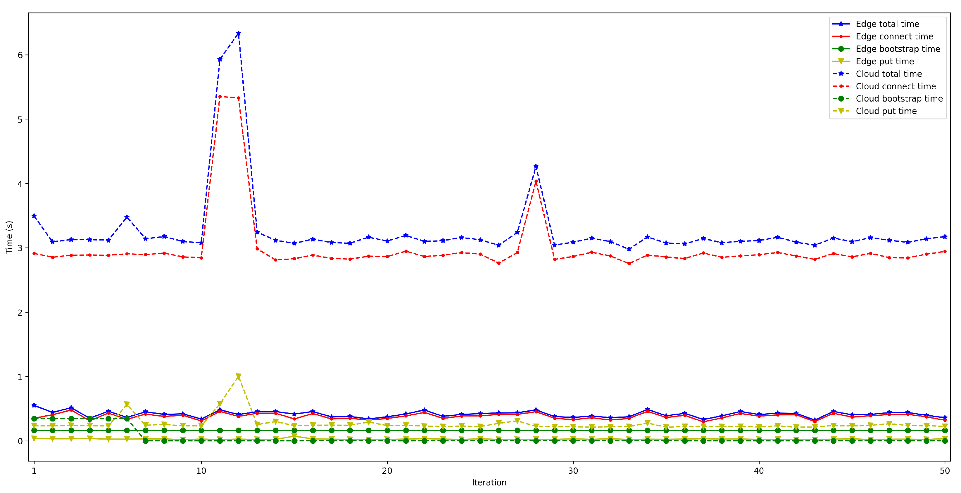
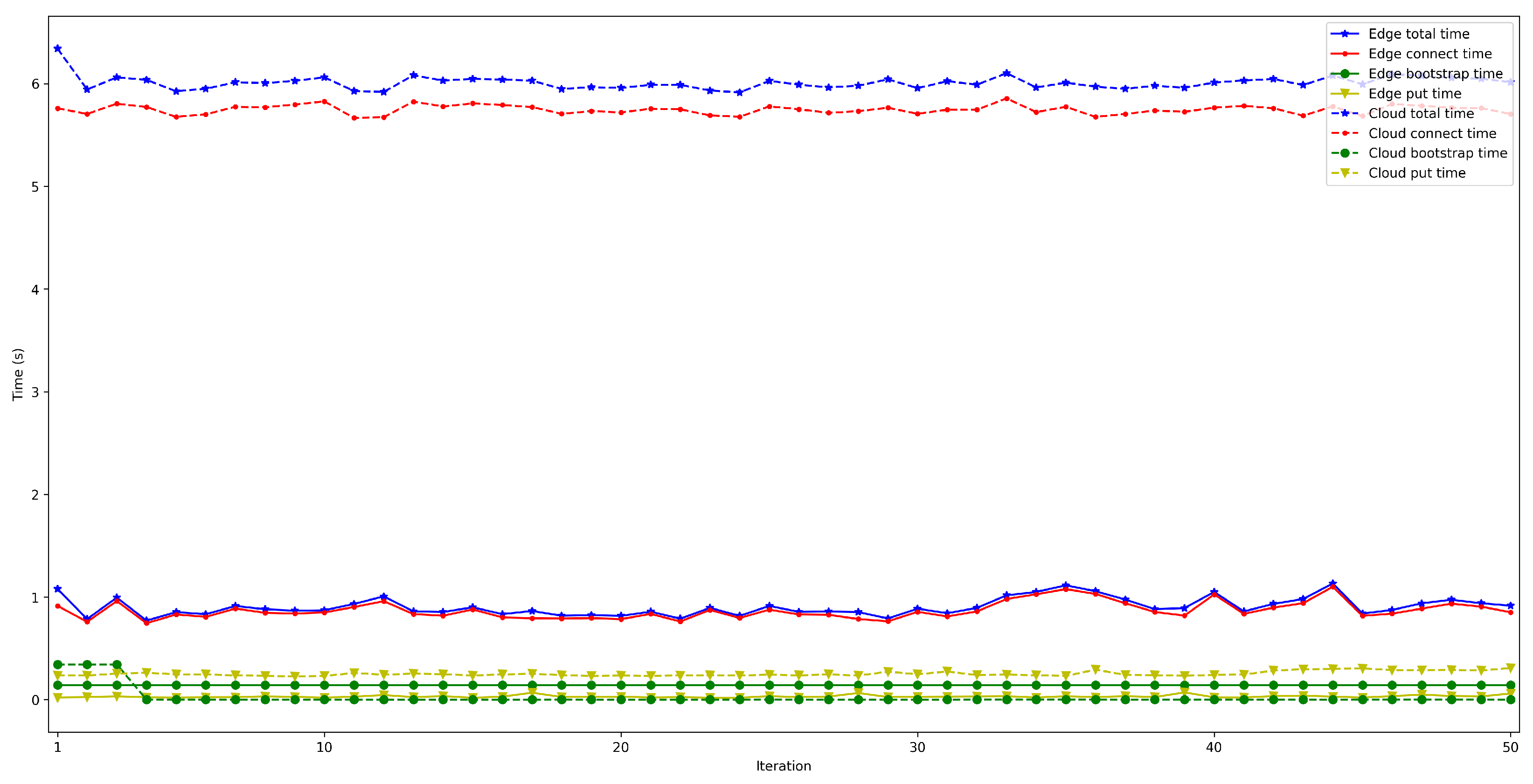
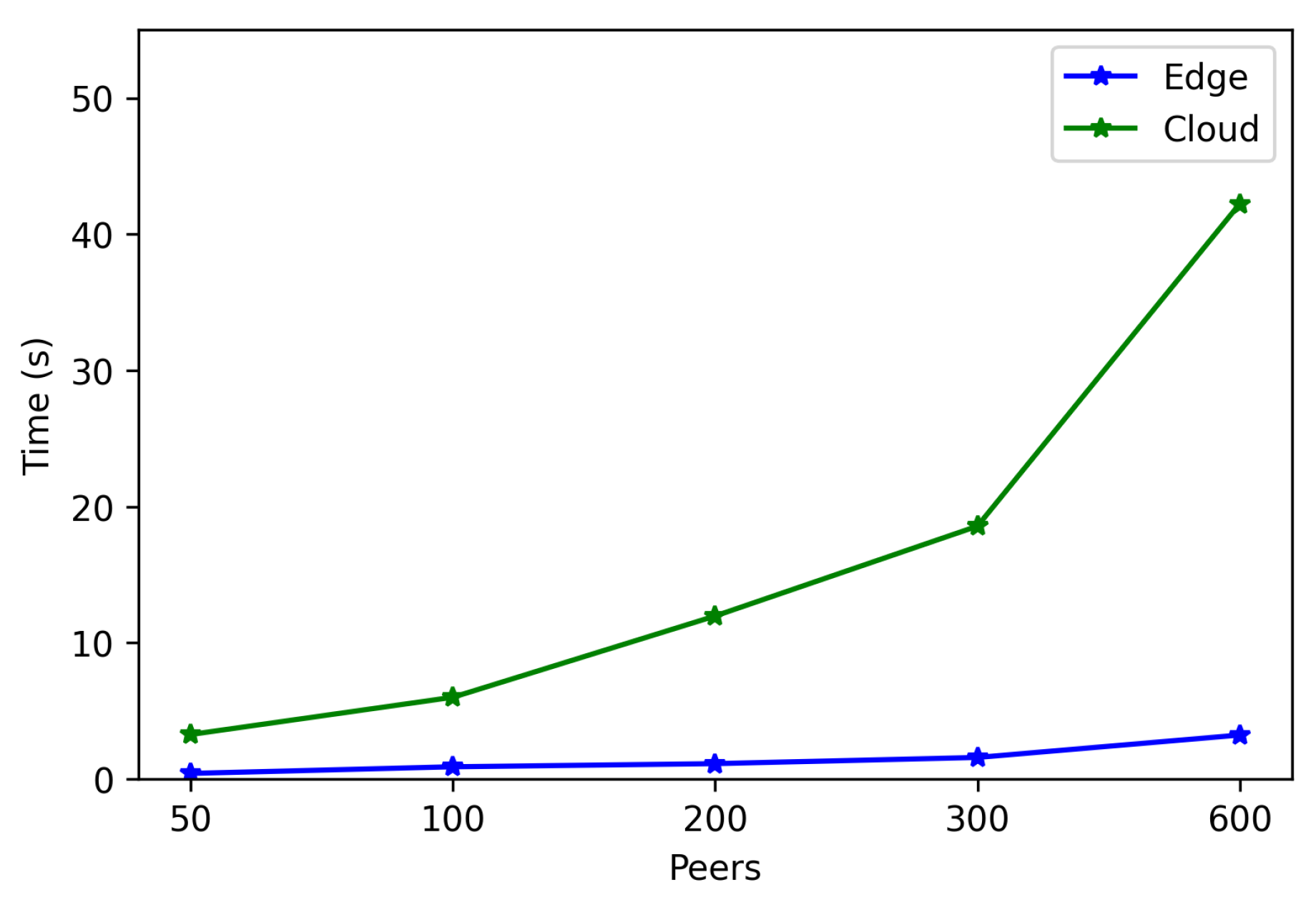
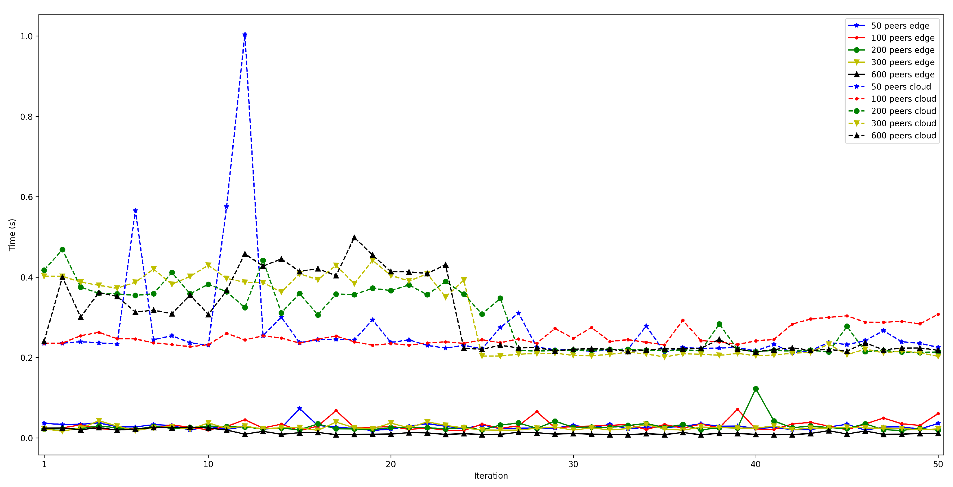
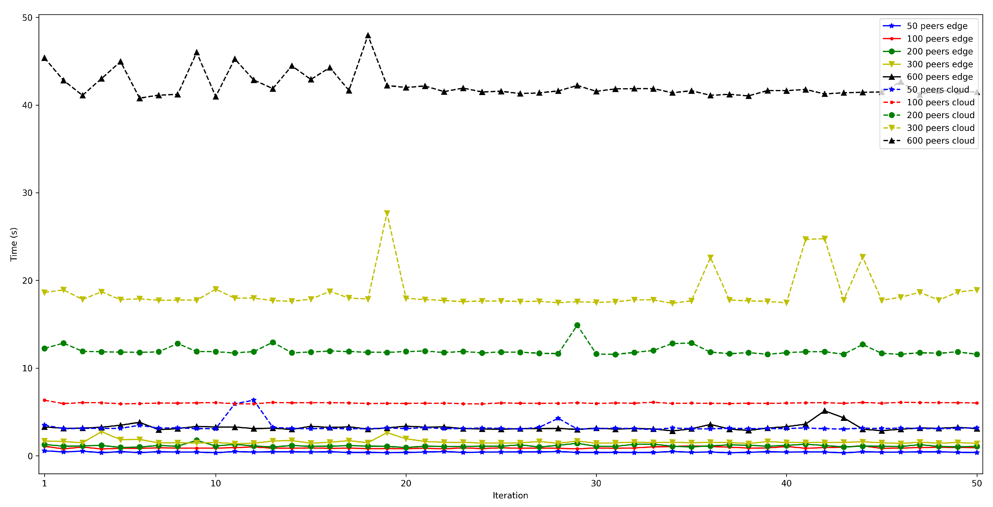
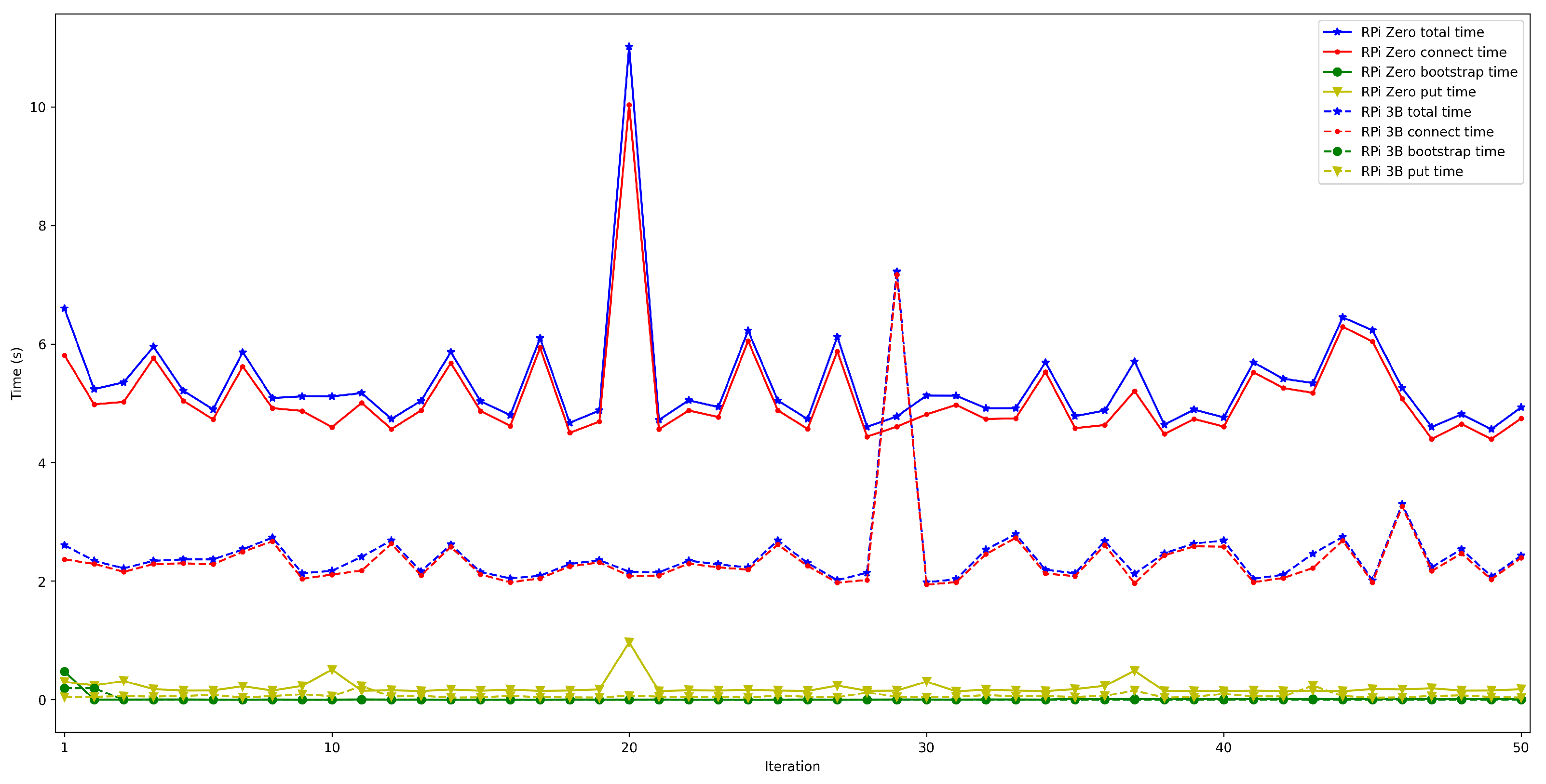
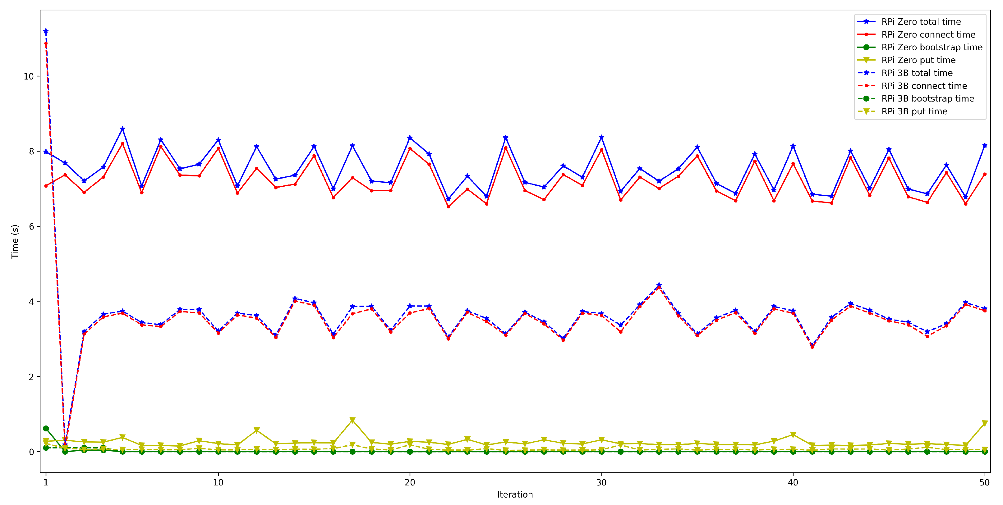
- . For this latency, tests were as for . The performed experiments show that latency depends directly on the number of connected peers. For the edge scenario, latency increases about 0.4 s per 100 peers, while in the cloud scenario such a time increases by 6 s.
- -
- . To measure this latency, tests were performed with 1000 messages that were sent sequentially from one node in a network to another in a different network. The average latency obtained for these experiments was 1.18 s.
- -
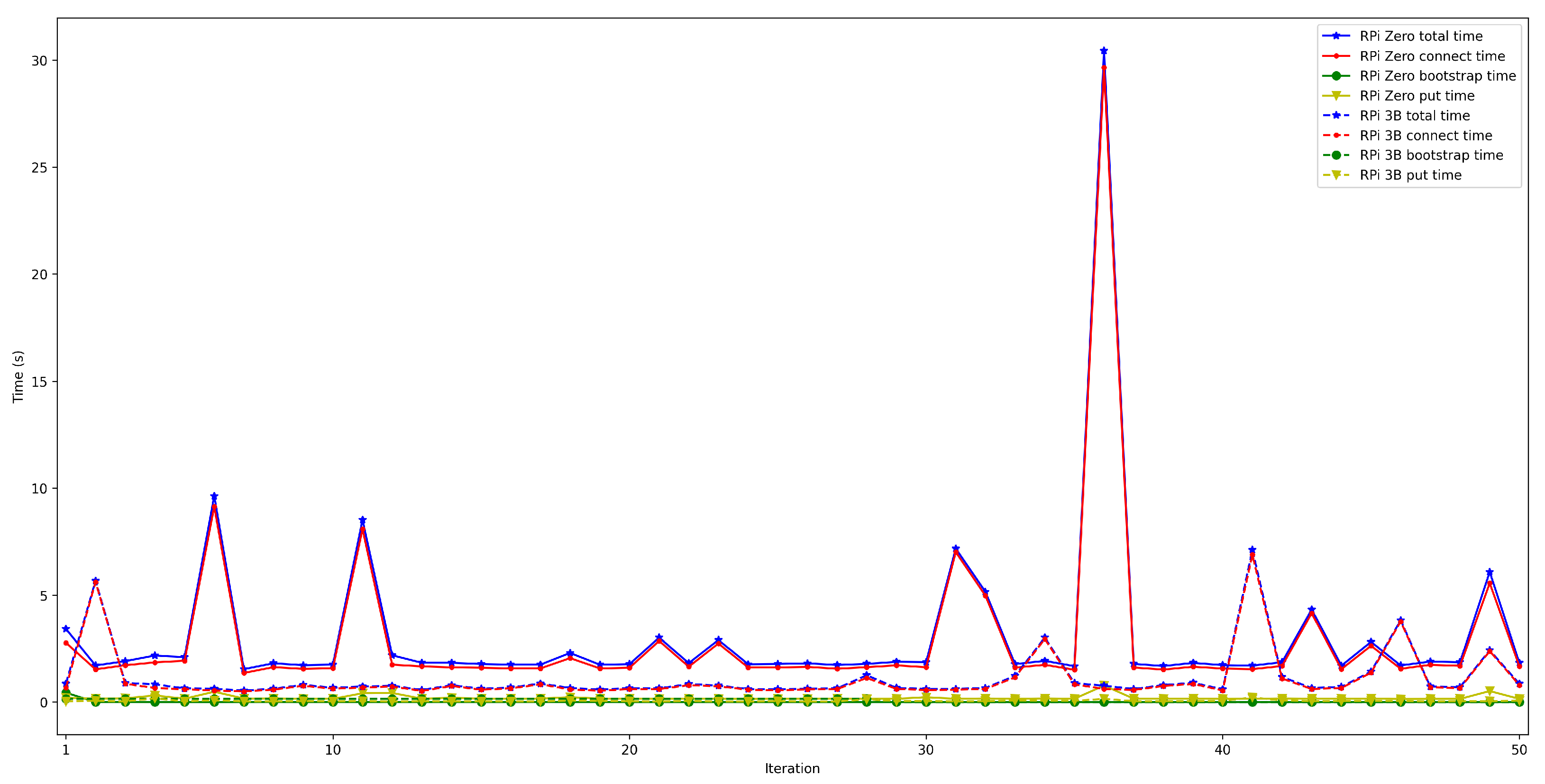
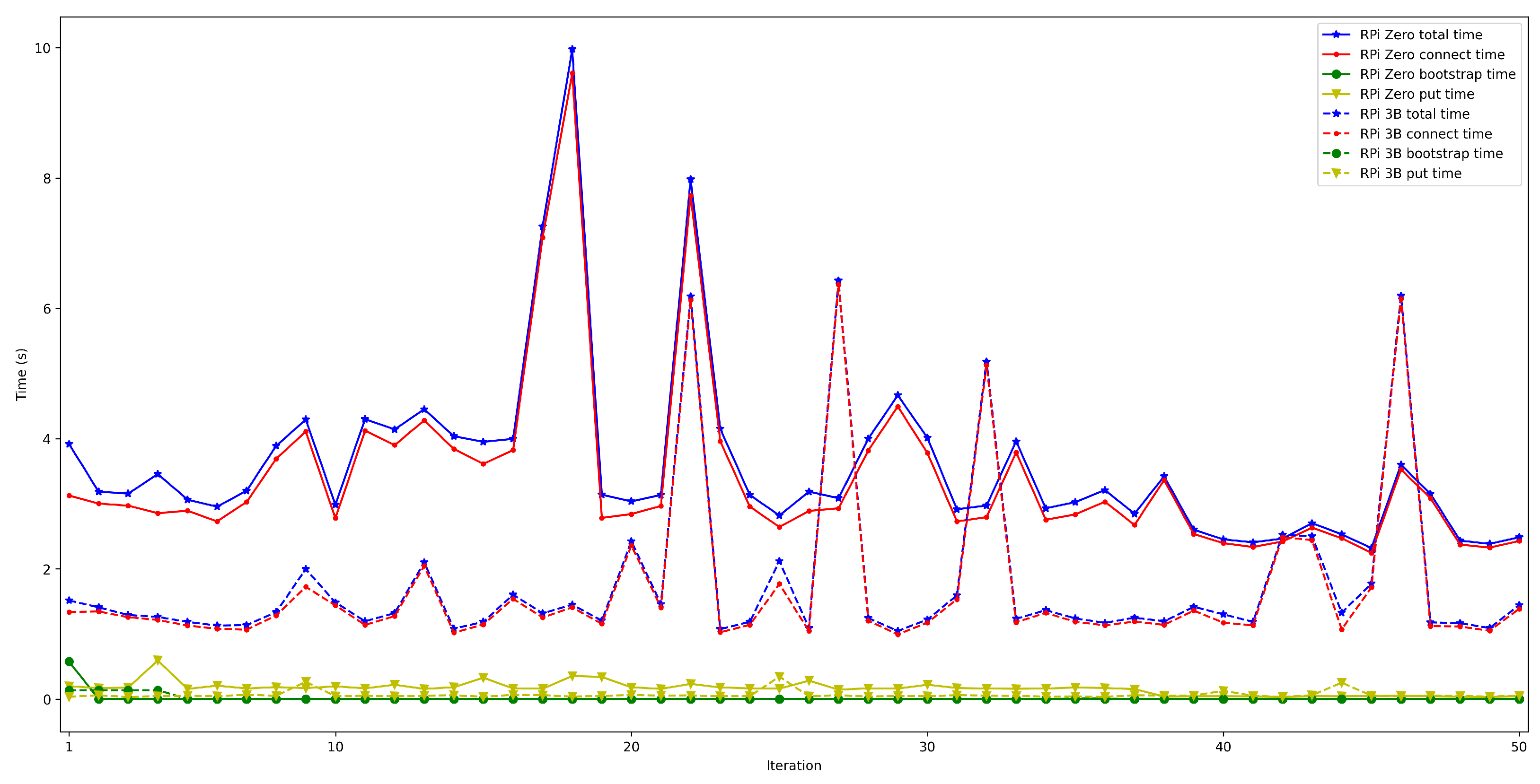
- . This latency was measured in the same way as for . The obtained results show a latency that oscillates between 100 and 150 ms for the edge scenario and between 200 and 1000 ms for the cloud scenario. In addition, the performed experiments allowed for concluding that this latency does not depend on the number of connected peers.
- The main detected challenges, as well as further research areas, are:
- -
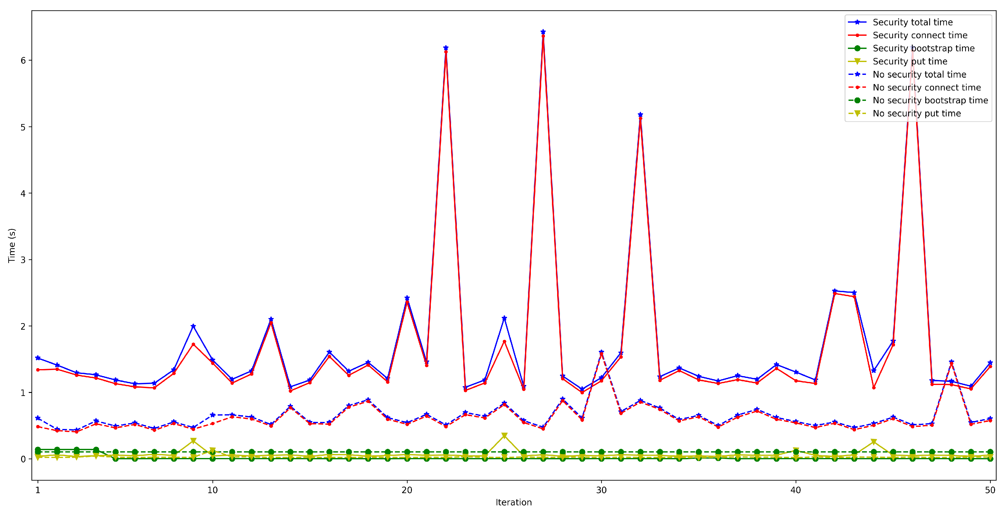
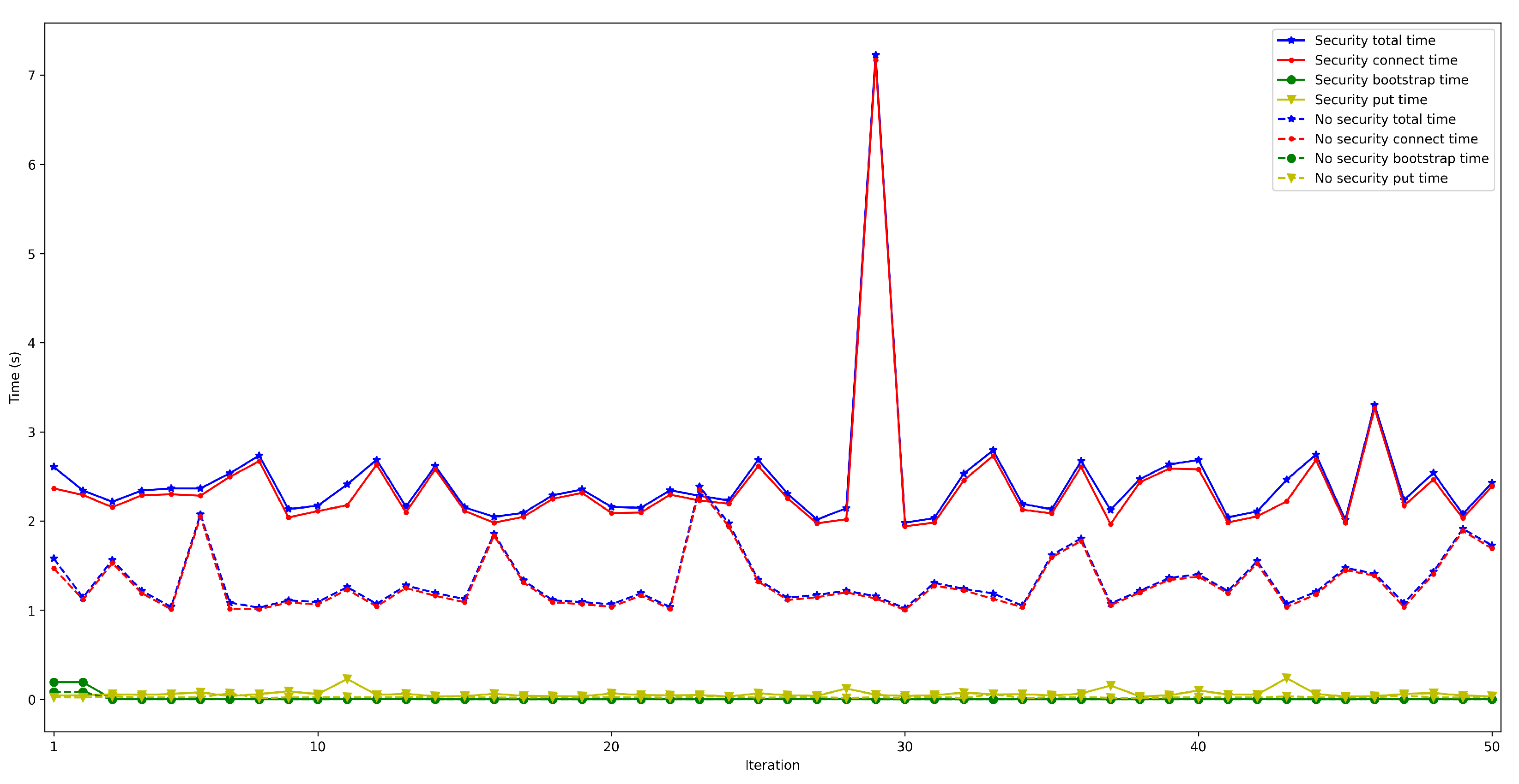
- Future developers will have to design their OEC systems to reach a trade-off between security level and latency by disabling certain security features under different circumstances or by devising novel security schemes.
- -
- The most critical aspects related to the implementation of practical OEC systems are the ones associated with the OEC Network Layer, which provides services for P2P communications (e.g., peer discovery, peer routing, data routing, and resource sharing). Specifically, the implementation of the proposed architecture relies on libp2p, the modular and extensible P2P network stack used by IPFS. More and more technologies are becoming available for such an implementation, but design trade-offs between the different requirements need to be considered (e.g., Kademlia DHT is robust for routing in terms of message losses and simplifies network tracing, but it is slower than other traditional recursive routing strategies).
- -
- When deploying an IoT OEC system, hardware requirements must be carefully analyzed and then empirical tests should be performed in order to select the most appropriate IoT nodes and OEC gateways.
- -
- The proposed OEC communications architecture, the used protocols and technologies, as well as the experiments outlined throughout this article, were selected having in mind a specific OEC scenario and set of requirements. Therefore, the obtained latency results should not be directly generalized to every OEC scenario. Nonetheless, the interested OEC system developers and researchers can make use of the provided source code to replicate the experiments in different scenarios and to adapt them to other requirements (e.g., cost, consumption, security level, scalability, mobility).
6. Conclusions
Author Contributions
Funding
Conflicts of Interest
References
- HIS. Internet of Things (IoT) Connected Devices Installed Base Worldwide from 2015 to 2025 (In Billions). Available online: https://bit.ly/3n6aQDO (accessed on 1 August 2022).
- Kshetri, N. Can Blockchain Strengthen the Internet of Things? IT Prof. 2017, 19, 68–72. [Google Scholar] [CrossRef]
- Fraga-Lamas, P.; Lopes, S.I.; Fernández-Caramés, T.M. Green IoT and Edge AI as Key Technological Enablers for a Sustainable Digital Transition towards a Smart Circular Economy: An Industry 5.0 Use Case. Sensors 2021, 21, 5745. [Google Scholar] [CrossRef] [PubMed]
- Froiz-Míguez, I.; Lopez-Iturri, P.; Fraga-Lamas, P.; Celaya-Echarri, M.; Blanco-Novoa, Ó.; Azpilicueta, L.; Falcone, F.; Fernández-Caramés, T.M. Design, Implementation, and Empirical Validation of an IoT Smart Irrigation System for Fog Computing Applications Based on LoRa and LoRaWAN Sensor Nodes. Sensors 2020, 20, 6865. [Google Scholar] [CrossRef] [PubMed]
- Huang, X.; Yu, R.; Liu, J.; Shu, L. Parked Vehicle Edge Computing: Exploiting Opportunistic Resources for Distributed Mobile Applications. IEEE Access 2018, 6, 66649–66663. [Google Scholar] [CrossRef]
- Habib ur Rehman, M.; Batool, A.; Salah, K. The Rise of Proximal Mobile Edge Servers. IT Prof. 2019, 21, 26–32. [Google Scholar] [CrossRef]
- Chamarajnagar, R.; Ashok, A. Opportunistic Mobile IoT with Blockchain Based Collaboration. In Proceedings of the 2018 IEEE Global Communications Conference (GLOBECOM), Abu Dhabi, United Arab Emirates, 9–13 December 2018; pp. 1–6. [Google Scholar] [CrossRef]
- Silva, R.; Silva, J.S.; Boavida, F. Opportunistic fog computing: Feasibility assessment and architectural proposal. In Proceedings of the 2017 IFIP/IEEE Symposium on Integrated Network and Service Management (IM), Lisbon, Portugal, 8–12 May 2017; pp. 510–516. [Google Scholar] [CrossRef]
- Ayele, E.D.; Meratnia, N.; Havinga, P.J.M. Towards a New Opportunistic IoT Network Architecture for Wildlife Monitoring System. In Proceedings of the 2018 9th IFIP International Conference on New Technologies, Mobility and Security (NTMS), Paris, France, 26–28 February 2018; pp. 1–5. [Google Scholar] [CrossRef]
- Tang, C.; Wei, X.; Zhu, C.; Wang, Y.; Jia, W. Mobile Vehicles as Fog Nodes for Latency Optimization in Smart Cities. IEEE Trans. Veh. Technol. 2020, 69, 9364–9375. [Google Scholar] [CrossRef]
- Ebert, C.; Louridas, P.; Fernández-Caramés, T.M.; Fraga-Lamas, P. Blockchain Technologies in Practice. IEEE Softw. 2020, 37, 17–25. [Google Scholar] [CrossRef]
- Núñez-Gómez, C.; Caminero, B.; Carrión, C. HIDRA: A Distributed Blockchain-Based Architecture for Fog/Edge Computing Environments. IEEE Access 2021, 9, 75231–75251. [Google Scholar] [CrossRef]
- Fernández-Caramés, T.M.; Fraga-Lamas, P. Design of a Fog Computing, Blockchain and IoT-Based Continuous Glucose Monitoring System for Crowdsourcing mHealth. Proceedings 2019, 4, 37. [Google Scholar] [CrossRef]
- Alharbi, H.A.; Aldossary, M. Energy-Efficient Edge-Fog-Cloud Architecture for IoT-Based Smart Agriculture Environment. IEEE Access 2021, 9, 110480–110492. [Google Scholar] [CrossRef]
- Simaan, M.; Cruz, J.B. On the Stackelberg strategy in nonzero-sum games. J. Optim. Theory Appl. 1973, 11, 533–555. [Google Scholar] [CrossRef]
- Mohamed, N.; Al-Jaroodi, J.; Jawhar, I.; Noura, H.; Mahmoud, S. UAVFog: A UAV-based fog computing for Internet of Things. In Proceedings of the 2017 IEEE SmartWorld, Ubiquitous Intelligence & Computing, Advanced & Trusted Computed, Scalable Computing & Communications, Cloud & Big Data Computing, Internet of People and Smart City Innovation (SmartWorld/SCALCOM/UIC/ATC/CBDCom/IOP/SCI), San Francisco, CA, USA, 4–8 August 2017; pp. 1–8. [Google Scholar] [CrossRef]
- Sharma, P.K.; Chen, M.-Y.; Park, J.H. A Software Defined Fog Node Based Distributed Blockchain Cloud Architecture for IoT. IEEE Access 2018, 6, 115–124. [Google Scholar] [CrossRef]
- Sung, Y.; Sharma, P.K.; Lopez, E.M.; Park, J.H. FS-OpenSecurity: A Taxonomic Modeling of Security Threats in SDN for Future Sustainable Computing. Sustainability 2016, 9, 919. [Google Scholar] [CrossRef]
- AllJoyn. AllJoyn Framework, Linux Found. Collaborative Projects. Available online: https://openconnectivity.org/technology/reference-implementation/alljoyn/ (accessed on 1 August 2022).
- Fraga-Lamas, P.; Lopez-Iturri, P.; Celaya-Echarri, M.; Blanco-Novoa, O.; Azpilicueta, L.; Varela-Barbeito, J.; Fernandez-Carames, T.M. Design and Empirical Validation of a Bluetooth 5 Fog Computing Based Industrial CPS Architecture for Intelligent Industry 4.0 Shipyard Workshops. IEEE Access 2020, 8, 45496–45511. [Google Scholar] [CrossRef]
- Bulić, P.; Kojek, G.; Biasizzo, A. Data Transmission Efficiency in Bluetooth Low Energy Versions. Sensors 2019, 19, 3746. [Google Scholar] [CrossRef]
- Bluetooth® Core Specification Version 5.0 Feature Enhancements. Available online: https://www.bluetooth.com/bluetooth-resources/bluetooth-5-go-faster-go-further/ (accessed on 1 September 2022).
- Pérez-Díaz-De-Cerio, D.; Hernández-Solana, Á.; García-Lozano, M.; Bardají, A.V.; Valenzuela, J.L. Speeding Up Bluetooth Mesh. IEEE Access 2021, 9, 93267–93284. [Google Scholar] [CrossRef]
- Nordic nRF52840-DK, Datasheet. Available online: https://infocenter.nordicsemi.com/pdf/nRF52840_OPS_v0.5.pdf (accessed on 27 June 2022).
- Fraga-Lamas, P.; Varela-Barbeito, J.; Fernández-Caramés, T.M. Next Generation Auto-Identification and Traceability Technologies for Industry 5.0: A Methodology and Practical Use Case for the Shipbuilding Industry. IEEE Access 2021, 9, 140700–140730. [Google Scholar] [CrossRef]
- Max-Onakpoya, E.; Madamori, S.; Baker, C.E. Utilizing Opportunistic Social Networks for Remote Patient Monitoring in Rural Areas. In Proceedings of the 1st ACM International Workshop on Technology Enablers and Innovative Applications for Smart Cities and Communities (TESCA’19). Association for Computing Machinery, New York, NY, USA, 13–14 November 2019; pp. 46–49. [Google Scholar] [CrossRef]
- Karvonen, H.; Mikhaylov, K.; Hämäläinen, M.; Iinatti, J.; Pomalaza- Ráez, C. Experimental performance evaluation of BLE 4 versus BLE 5 in indoors and outdoors scenarios. In Advances in Body Area Networks; Springer: Cham, Switzerland, 2017; pp. 235–251. [Google Scholar]
- Ashraf, S.; Alfandi, O.; Ahmad, A.; Khattak, A.M.; Hayat, B.; Kim, K.H.; Ullah, A. Bodacious-Instance Coverage Mechanism for Wireless Sensor Network. Wirel. Commun. Mob. Comput. 2020, 2020, 8833767. [Google Scholar] [CrossRef]
- de Jong, L. Decentralized Link Sharing, towards a Framework for Decentralized Applications. Master’s Thesis, University of Groningen, Groningen, The Netherlands, 2015. Available online: https://www.cs.rug.nl/~aiellom/tesi/dejong.pdf (accessed on 1 September 2022).
- Antunes, J. PulsarCast. Scaling PubSub over the Distributed Web. Available online: http://web.tecnico.ulisboa.pt/~ist14191/papers/TR-75993-joao-antunes.pdf (accessed on 1 September 2022).
- QUIC Official Webpage. Available online: https://quicwg.org (accessed on 1 September 2022).
- CJDNS Official Webpage. Available online: https://github.com/cjdelisle/cjdns (accessed on 1 September 2022).
- UDT Official Webpage. Available online: https://udt.sourceforge.io (accessed on 1 September 2022).
- WEBRTC Official Webpage. Available online: https://webrtc.org (accessed on 1 September 2022).
- Adamsky, F. Analysis of Bandwidth Attacks in a Bittorrent Swarm. Doctoral Thesis, University of London, London, UK, 2016. Available online: https://openaccess.city.ac.uk/id/eprint/16158/ (accessed on 1 October 2022).
- Maymounkov, P.; Mazières, D. Kademlia: A Peer-to-Peer Information System Based on the XOR Metric. In Peer-to-Peer Systems. IPTPS 2002; Druschel, P., Kaashoek, F., Rowstron, A., Eds.; Lecture Notes in Computer, Science; Springer: Berlin/Heidelberg, Germany, 2002; Volume 2429, pp. 53–65. [Google Scholar] [CrossRef]
- Cheshire, S.; Krochmal, M. Multicast DNS. Internet Engineering Task Force (IETF). 2013. Available online: https://www.rfc-editor.org/rfc/rfc6762 (accessed on 1 August 2022).
- Mastorakis, S. Peer-to-Peer Data Sharing in Named Data Networking. Internet Research Laboratory. Ph.D. Thesis, University of California, Los Angeles, CA, USA, 2019. Available online: https://escholarship.org/content/qt372316q8/qt372316q8_noSplash_6ecda766439f4e7bbd0d20bfd442792c.pdf (accessed on 1 September 2022).
- Kaashoek, M.F.; Karger, D.R. Koorde: A Simple Degree-Optimal Distributed Hash Table. In Peer-to-Peer Systems II. IPTPS 2003; Kaashoek, M.F., Stoica, I., Eds.; Lecture Notes in Computer, Science; Springer: Berlin/Heidelberg, Germany, 2003; Volume 2735, pp. 98–107. [Google Scholar] [CrossRef]
- Naik, A.R.; Keshavamurthy, B.N. Next level peer-to-peer overlay networks under high churns: A survey. Peer-Peer Netw. Appl. 2020, 13, 905–931. [Google Scholar] [CrossRef]
- Stoica, I.; Morris, R.; Liben-Nowell, D.; Karger, D.R.; Kaashoek, M.F.; Dabek, F.; Balakrishnan, H. Chord: A scalable peer-to-peer lookup protocol for internet applications. Ieee/Acm Trans. Netw. 2003, 11, 17–32. [Google Scholar] [CrossRef]
- Woungang, I.; Tseng, F.H.; Lin, Y.H.; Chou, L.D.; Chao, H.C.; Obaidat, M.S. MR-Chord: Improved Chord Lookup Performance in Structured Mobile P2P Networks. IEEE Syst. J. 2015, 9, 743–751. [Google Scholar] [CrossRef]
- Muchtar, F.; Singh, P.K.; Ahmmad, S.N.Z.; Ambar, R.; Hanafi, H.F.; Fadilah, S.I. P2P Over MANET: A Review and Its Conceptual Framework. In Proceedings of the 2018 Fifth International Conference on Parallel, Distributed and Grid Computing (PDGC), Solan, India, 20–22 December 2018; pp. 48–53. [Google Scholar] [CrossRef]
- Interactive Connectivity Establishment (ICE). RFC 8845. Available online: https://www.rfc-editor.org/rfc/rfc8445.html (accessed on 1 September 2022).
- Druschel, P.; Kaashoek, M.F.; Rowstron, A.I.T. (Eds.) Peer-to-Peer Systems. In Proceedings of the First International Workshop, IPTPS 2002, Cambridge, MA, USA, 7–8 March 2002; Lecture Notes in Computer Science. Springer: Berlin/Heidelberg, Germany, 2002; Volume 2429. [Google Scholar]
- Fernández-Caramés, T.M.; Fraga-Lamas, P. A Review on the Use of Blockchain for the Internet of Things. IEEE Access 2018, 6, 32979–33001. [Google Scholar] [CrossRef]
- Guidi, B.; Michienzi, A.; Ricci, L. A libP2P Implementation of the Bitcoin Block Exchange Protocol. In Proceedings of the 2nd International Workshop on Distributed Infrastructure for Common Good (DICG’21), Virtual Event, 6–10 December 2021; Association for Computing Machinery: New York, NY, USA, 2021; pp. 1–4. [Google Scholar] [CrossRef]
- IPFS. The Interplanetary File System (IPFS). Available online: https://ipfs.io/ (accessed on 1 August 2022).
- IETF. The Transport Layer Security (TLS) Protocol Version 1.3. Available online: https://bit.ly/3NGbuVO (accessed on 1 August 2022).
- IETF. The Transport Layer Security (TLS) Protocol Version 1.3—Cipher Suites. Available online: https://bit.ly/3z4m4lg (accessed on 1 August 2022).
- Perrin, T. The Noise Protocol Framework. Available online: https://bit.ly/3POdBIY (accessed on 1 August 2022).
- Perrin, T. The Noise Protocol Framework DH Functions, Cipher Functions, and Hash Functions. Available online: https://bit.ly/38TvRjp (accessed on 1 August 2022).
- Go-libp2p Official Repository. Available online: https://github.com/libp2p/go-libp2p (accessed on 1 August 2022).
- Official Gitlab Repository of the ORBALLO Project. Available online: https://gitlab.com/orballo_project/opportunistic-ble-mesh (accessed on 1 September 2022).
- Fernández-Caramés, T.M.; Fraga-Lamas, P. Teaching and Learning IoT Cybersecurity and Vulnerability Assessment with Shodan through Practical Use Cases. Sensors 2020, 20, 3048. [Google Scholar] [CrossRef] [PubMed]
- Suárez-Albela, M.; Fraga-Lamas, P.; Castedo, L.; Fernández-Caramés, T.M. Clock Frequency Impact on the Performance of High-Security Cryptographic Cipher Suites for Energy-Efficient Resource-Constrained IoT Devices. Sensors 2019, 19, 15. [Google Scholar] [CrossRef]



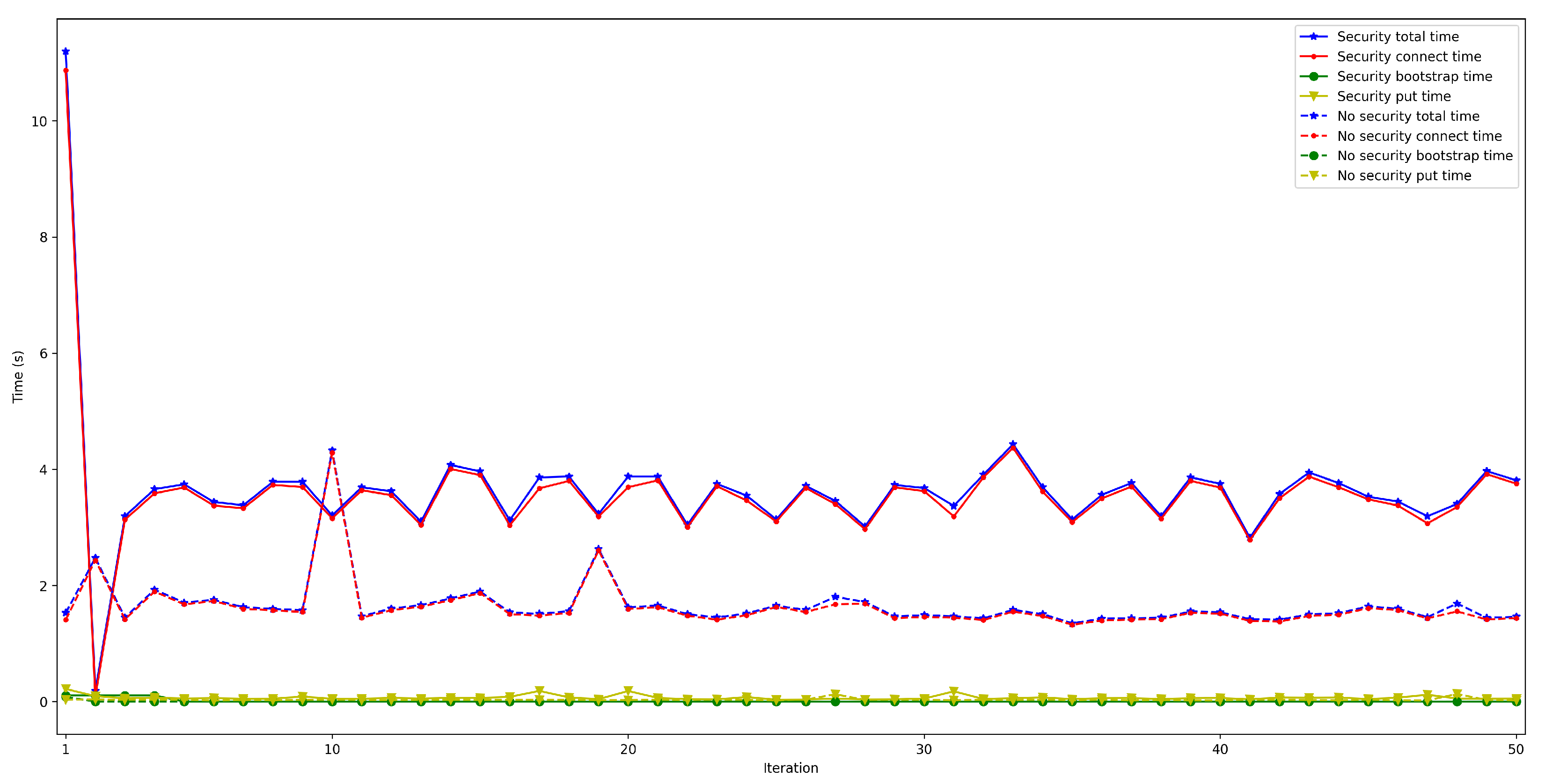
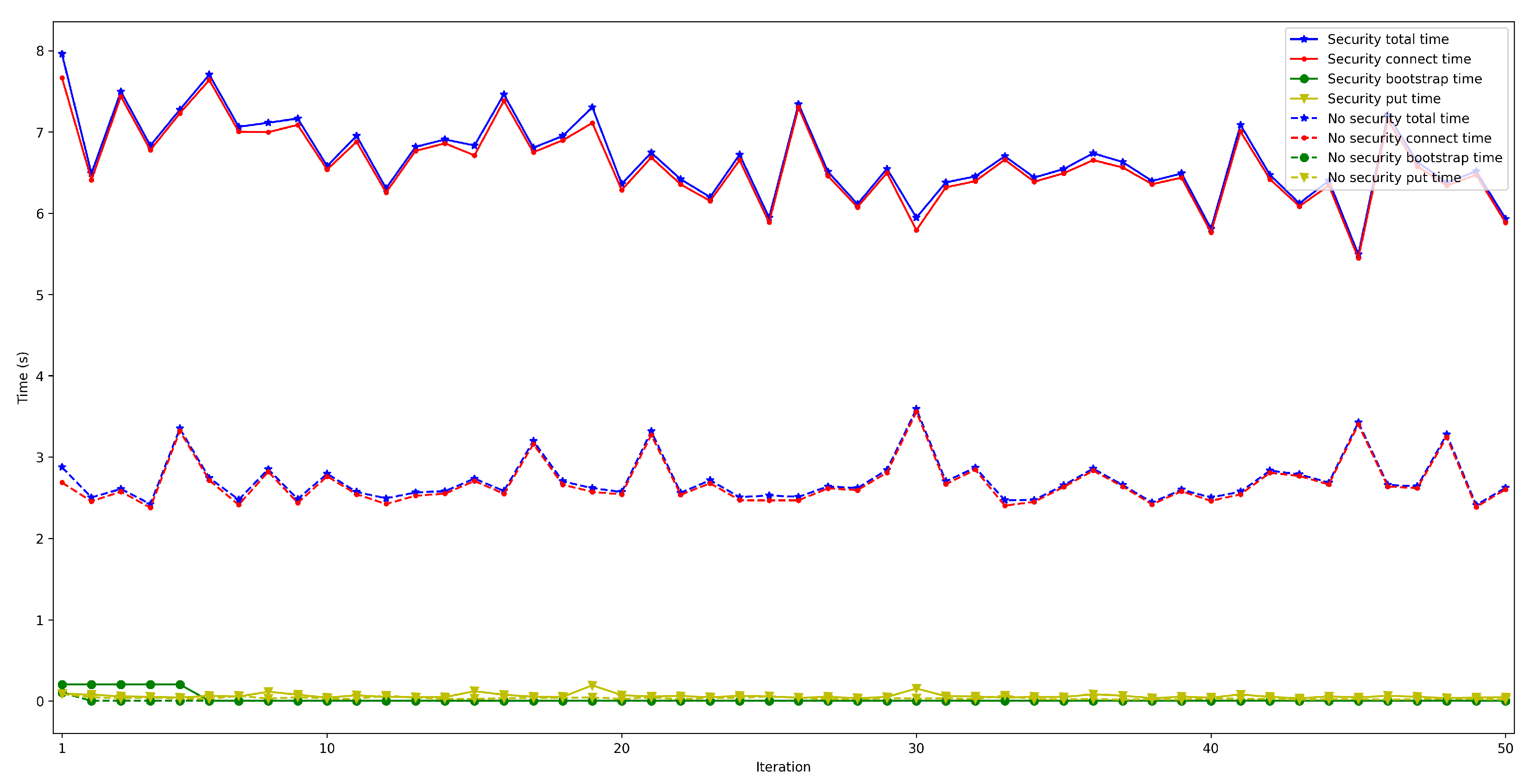
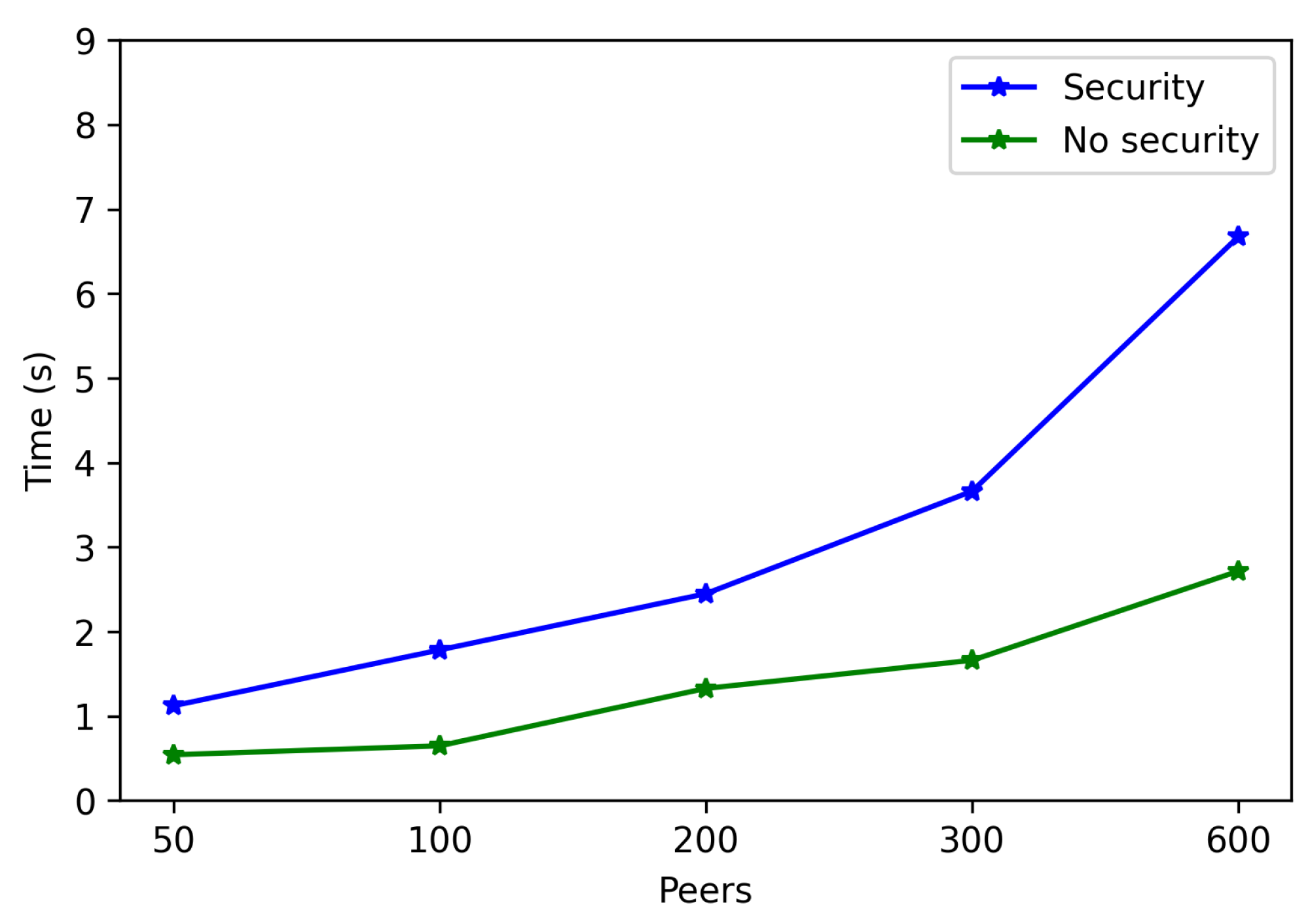
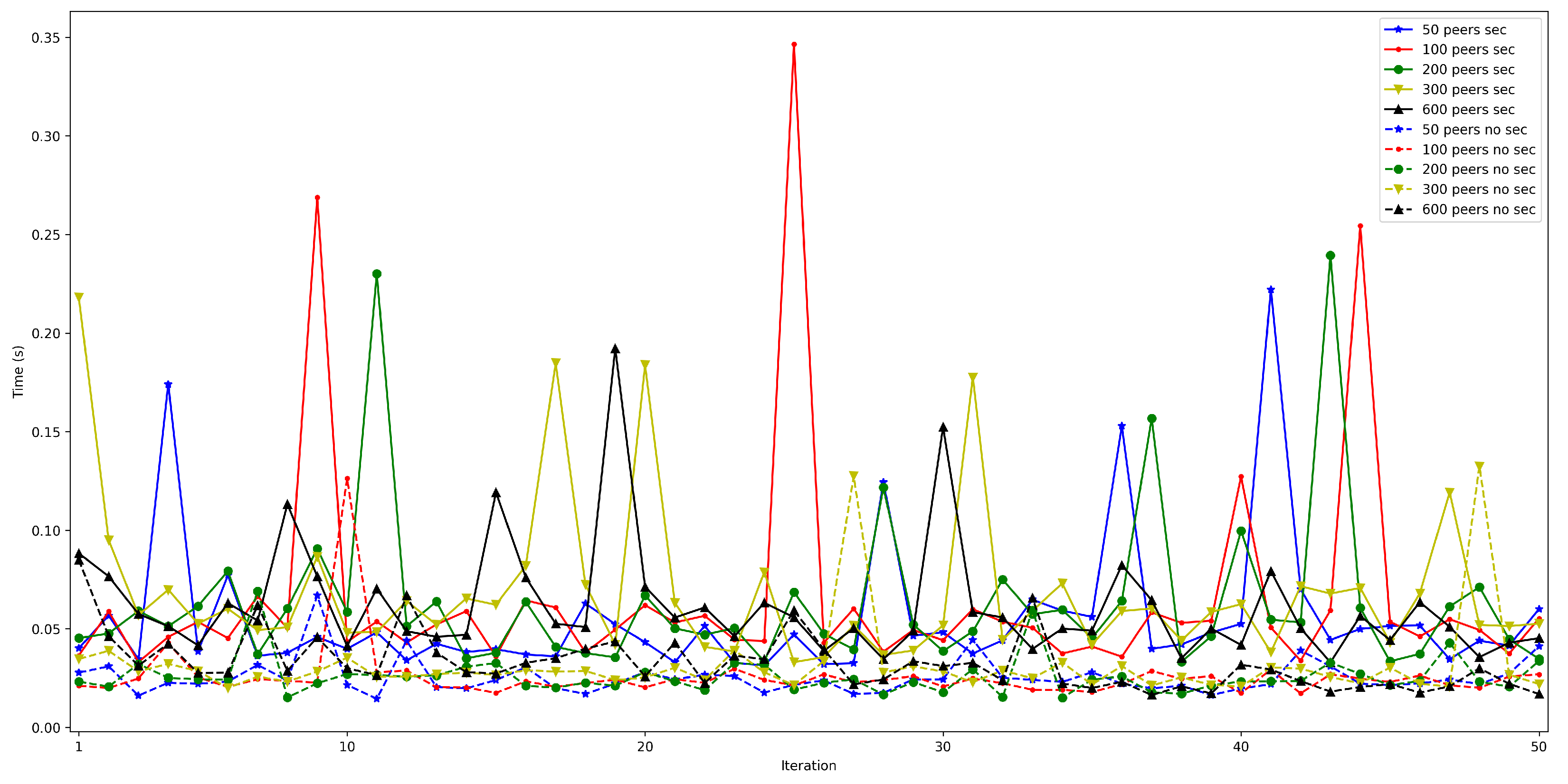

| System | Architecture Type | Application Field | Decentralized | Communication Technologies | Security Mechanisms | Distributed | Scalable | Modular | Resource Sharing | Data Routing | Node Discovery | Hardware | Other Features |
|---|---|---|---|---|---|---|---|---|---|---|---|---|---|
| [5] (Theoretical Article) | Edge Computing | Parked Vehicles | No | - | Asymmetric and symmetric key-based encryption and digital signatures | Yes | Yes | - | Yes | No | No | - | Parked vehicles act as Edge Computing nodes |
| [6] | Mobile Edge Computing | - | No | Wi-Fi/GSM | - | Yes | Yes | No | No | No | Yes | Android device | Minimize latency, lower dependencies on Internet connectivity, and reduce the cost of using cloud services |
| [7] | Blockchain | - | Yes | Ethernet | SHA-256 | No | No | No | Yes | No | No | Raspberry Pi 3, Dell 5100 | The obtained latency and resource use metrics are similar to the ones for traditional centralized edge approaches |
| [8] (Theoretical Article) | Fog Computing | - | Yes | - | Server Virtualization | Yes | Yes | Yes | No | No | No | - | High number of potentially connected neighbors and small number of hops |
| [16] | Fog Computing | UAVs | No | WiFi | - | Yes | Yes | No | No | Yes | Yes | Adafruit CC3000 | Low latency services, location aware services, better mobility and access control, better Quality of Service (QoS), more efficient communications |
| [12] | Fog Computing | - | Yes | - | SHA-256 | Yes | No | Yes | No | No | No | Raspberry Pi 4 Model B | Fault-tolerant, secure and auditable |
| [14] (Theoretical Article) | Edge-Fog-Cloud | Agriculture | No | NB-IoT, WiFi, Zigbee, 5G | - | Yes | Yes | Yes | No | No | No | - | Reduction of energy consumption, CO2 emissions and network traffic |
| [17] | Blockchain Cloud | - | No | - | FS-OpenSecurity (proprietary development [18]) | Yes | Yes | No | No | Yes | No | Intel i5 16 GB DDR3-RAM Laptop | High availability, real-time data delivery, high scalability, security, resiliency, and low latency |
| [9] | Traditional LPWAN (Low-Power Wide Area Network) Architecture | Wildlife monitoring | No | LoRa | - | Yes | Yes | No | No | Yes | Yes | Adafruit Feather 32u4 RFM95 - 868 MHz | High delivery ratio, low latency, low energy |
| Solution Described in this Article | Mobile Fog Computing | - | Yes | Bluetooth 5, WIFI, 4G | TLS 1.3 | Yes | Yes | Yes | Yes | Yes | Yes | Raspberry Pi 3 Model B, Raspberry Pi 3 Model B+, Raspberry Pi Zero | Low cost solution, low latency, SBC-based gateways, for resource-constraint IoT nodes |
| Referenced System | Physical Layer | Transport Layer | Network Layer | Application Layer |
|---|---|---|---|---|
| [5] (Theoretical Article) | - | - | - | Vehicular-edge computing proprietary protocol |
| [6] | 802.11/GSM | - | - | - |
| [7] | - | TCP/IP | Blockchain-based proprietary protocols | - |
| [8] (Theoretical Article) | - | UDP | 6LowPAN & RPL | - |
| [9] | - | LoRaWAN | - | - |
| [12] | - | TCP/IP | Ethereum | - |
| [14] (Theoretical Article) | - | - | - | - |
| [16] | 802.11 | TCP/IP | UPnP | - |
| [17] | - | TCP/IP | Blockchain-based proprietary protocols | - |
| System described in this article | - | TCP/IP | LibP2P | - |
| Layer | Protocol | Reliability | Packet Loss Recovery | Routed Destination | Forwarding | Encryption |
|---|---|---|---|---|---|---|
| Physical | 802.11/GSM | × | × | × | × | × |
| Transport | TCP | ✓ | × | × | × | × |
| Transport | UDP | × | × | × | × | × |
| Transport | LoRaWAN | ✓ | × | ✓ | × | ✓ |
| Network | Blockchain-based proprietary protocols | × | ✓ | ✓ | × | ✓ |
| Network | 6LowPAN/RPL | × | × | ✓ | ✓ | × |
| Network | UPnP | × | × | × | × | × |
| Network | Ethereum | × | ✓ | ✓ | × | ✓ |
| Network | LibP2P | × | ✓ | ✓ | ✓ | ✓ |
| Application | Vehicle Edge Computing Proprietary protocol | × | × | × | × | ✓ |
| - | TCP + LibP2P | ✓ | ✓ | ✓ | ✓ | ✓ |
| Raspberry Pi 3 B | Raspberry Pi 3 B+ | Raspberry Pi Zero W | |
|---|---|---|---|
| SoC | 64-bit ARM Cortex-A53 Quad-Core | 64-bit ARM Cortex-A53 Quad-Core | 32-bit ARM1176JZF-S Single-Core |
| Core | Broadcom BCM2837 | Broadcom BCM2837 | Broadcom BCM2835 |
| GPU | Broadcom VideoCore IV | Broadcom Videocore-IV | Broadcom VideoCore IV |
| CPU Clock | 1.2 GHz | 1.4 GHz | 1 GHz |
| Memory | 1 GB | 1 GB | 512 MB |
| SPI/12C | Yes | Yes | Yes |
| Supported OS | Linux, Android Things, Windows 10 IoT Core | Linux, Android Things, Windows 10 IoT Core | Linux |
| Ethernet | 10/100 Mbit/s | 10/100/1000 Mbit/s | None |
| Wi-Fi/ Bluetooth | 2.4 GHz 802.11n/ Bluetooth 4.1 | 2.4/5 GHz 802.11ac/ Bluetooth 4.2 | 2.4 GHz 802.11n/ Bluetooth 4.1 |
| Current Consumption | 350 mA | 400 mA | 160 mA |
| Cost | USD38 | USD45 | USD10 |
| Project | Hardware | Cost (€) | #Units | Total (€) |
|---|---|---|---|---|
| Solution Described in this Article | Raspberry pi Zero W | 10.44 | 3 | 31.32 |
| Raspberry Pi 3 B+ | 51.43 | 3 | 154.29 | |
| NRF52840-DK | 49 | 6 | 294 | |
| PC cloud | 600 | 1 | 600 | |
| 1079.61 | ||||
| [9] | Adafruit Feather 32u4 RFM95 | 35.28 | 3 | 105.84 |
| LARANK 8 | 393.25 | 1 | 393.25 | |
| Adafruit Feather nRF52832 | 25.95 | 9 | 233.55 | |
| 732.64 | ||||
| [16] | Arduino board+Adafruit CC3000 Wi-Fi board | 48.95 | 1 | 48.95 |
| PC UAVFOG | 600 | 2 | 1200 | |
| PC cloud | 600 | 1 | 600 | |
| 1848.95 | ||||
| [7] | Raspberry Pi 3 A+ | 30.25 | 9 | 272.25 |
| Dell EMC Edge Gateway 5200 | 3.412.94 | 1 | 3412.94 | |
| 3685.19 | ||||
| [12] | Raspberry pi 4 | 60 | 9 | 540 |
| 540 | ||||
| [17] | Cloud Server (64 GB RAM and Intel i7) | 640/year | 6 | 3840 |
| Laptop (16 GB RAM and Intel i5) | 600 | 3 | 1800 | |
| 5640 | ||||
Publisher’s Note: MDPI stays neutral with regard to jurisdictional claims in published maps and institutional affiliations. |
© 2022 by the authors. Licensee MDPI, Basel, Switzerland. This article is an open access article distributed under the terms and conditions of the Creative Commons Attribution (CC BY) license (https://creativecommons.org/licenses/by/4.0/).
Share and Cite
Niebla-Montero, Á.; Froiz-Míguez, I.; Fraga-Lamas, P.; Fernández-Caramés, T.M. Practical Latency Analysis of a Bluetooth 5 Decentralized IoT Opportunistic Edge Computing System for Low-Cost SBCs. Sensors 2022, 22, 8360. https://doi.org/10.3390/s22218360
Niebla-Montero Á, Froiz-Míguez I, Fraga-Lamas P, Fernández-Caramés TM. Practical Latency Analysis of a Bluetooth 5 Decentralized IoT Opportunistic Edge Computing System for Low-Cost SBCs. Sensors. 2022; 22(21):8360. https://doi.org/10.3390/s22218360
Chicago/Turabian StyleNiebla-Montero, Ángel, Iván Froiz-Míguez, Paula Fraga-Lamas, and Tiago M. Fernández-Caramés. 2022. "Practical Latency Analysis of a Bluetooth 5 Decentralized IoT Opportunistic Edge Computing System for Low-Cost SBCs" Sensors 22, no. 21: 8360. https://doi.org/10.3390/s22218360
APA StyleNiebla-Montero, Á., Froiz-Míguez, I., Fraga-Lamas, P., & Fernández-Caramés, T. M. (2022). Practical Latency Analysis of a Bluetooth 5 Decentralized IoT Opportunistic Edge Computing System for Low-Cost SBCs. Sensors, 22(21), 8360. https://doi.org/10.3390/s22218360


